1
Virtual CAN Interface
Universal software interface for
STZP PC/CAN interfaces
User manual
Version 1.09
Mai 1998
Steinbeis Transferzentrum Prozeßautomatisierung
Doggenriedstr. 40, D-88250 Weingarten
Postfach 1261, D-88241 Weingarten
Tel. 0751-56146-0 Fax. 0751-56146-29
Virtual CAN Interface
Copyright
Copyright
All rights reserved for software, hardware and this user manual.
Copies are only allowed with explicit permission of Steinbeis
Transferzentrum Prozeßautomatisierung. The usual regulations of a
licence agreement are valid.
Steinbeis Transferzentrum Prozeßautomatisierung
Doggenriedstraße 40
D-88250 Weingarten
Tel.: ++49 - (0)751 - 56 146 - 0
Fax.: ++49 - (0)751 - 56 146 - 29
3
Virtual CAN Interface
Table of Contents
Table of contents
1. Introduction ..........................................................................................9
1.1. Fields of application.........................................................................9
1.2. Importand remarks to the manual..................................................10
1.3. Installation of VCI...........................................................................11
1.3.1. Installation of DOS-VCI ......................................................11
1.3.2. Installation of Windows-VCI (3.1, 95, NT) ...........................11
1.3.3. Additional Hints for Installation............................................12
1.4. Overview of VCI functionality.........................................................13
1.5. Message management ..................................................................14
1.5.1. Receive buffer .....................................................................14
1.5.2. Receive queue ....................................................................15
1.5.3. Transmit queue ...................................................................15
1.5.4. Remote buffer .....................................................................16
2. Interface description ..........................................................................17
2.1. Predefined return codes of VCI .....................................................17
2.2. Type definitions of callback handler ..............................................19
2.2.1. Receive interrupt handler ....................................................19
2.2.2. Exception handler................................................................20
2.2.3. Handler for string output......................................................21
2.2.4. Special Hints for Visual Basic 5+ ........................................22
2.3. State diagram for the board initialization .......................................23
2.4. Initialization of VCI .........................................................................24
2.4.1. VCI_Init................................................................................24
2.5. Functions for VCI support information ...........................................24
2.5.1. VCI_Get_LibType (ab Vers. 1.09) .......................................24
2.5.2. VCI_GetBrdNameByType (ab Vers. 1.09) ..........................25
2.5.3. VCI_GetBrdTypeByName (ab Vers. 1.09) ..........................26
2.6. Functions for board initialization ....................................................26
5
Virtual CAN Interface
Table of Contents
2.6.1. VCI_SetDownloadState (from vers. 1.09) ......................... 28
2.6.2. VCI_PrepareBoard ............................................................. 28
2.6.3. VCI_PrepareBoardMsg (Windows 3.1) .............................. 30
2.6.4. VCI_PrepareBoardVisBas (Visual Basic 5+, VCI V 1.09) .. 32
2.6.5. VCI_CancelBoard............................................................... 33
2.6.6. VCI_TestBoard ................................................................... 33
2.6.7. VCI_ReadBoardInfo............................................................ 34
2.6.8. VCI_ReadBoardStatus ....................................................... 35
2.6.9. VCI_ResetBoard................................................................. 36
2.7. Functions for CAN initialization ..................................................... 36
2.7.1. VCI_ReadCanInfo............................................................... 36
2.7.2. VCI_ReadCanStatus .......................................................... 37
2.7.3. VCI_InitCan ........................................................................ 38
2.7.4. VCI_SetAccMask................................................................ 40
2.7.5. VCI_ResetCan.................................................................... 41
2.7.6. VCI_StartCan ..................................................................... 41
2.8. Functions for the VCI configuration............................................... 42
2.8.1. VCI_ConfigQueue .............................................................. 42
2.8.2. VCI_AssignRxQueObj ........................................................ 44
2.8.3. VCI_ResetTimeStamp........................................................ 45
2.8.4. VCI_ConfigBuffer................................................................ 46
2.8.5. VCI_ReConfigBuffer ........................................................... 46
2.9. Reception of messages ................................................................ 47
2.9.1. VCI_ReadQueStatus .......................................................... 47
2.9.2. VCI_ReadQueObj............................................................... 48
2.9.3. VCI_ReadBufStatus ........................................................... 48
2.9.4. VCI_ReadBufData .............................................................. 49
2.10. Transmission of messages ......................................................... 50
2.10.1. VCI_TransmitObj .............................................................. 50
2.10.2. VCI_RequestObj............................................................... 51
2.10.3. VCI_UpdateBufObj ........................................................... 51
6
Virtual CAN Interface
Table of Contents
2.11. Used data types...........................................................................53
2.11.1. VCI-CAN-Object................................................................53
2.11.2. VCI-Board-Information ......................................................54
2.11.3. VCI-Board-Status ..............................................................54
2.11.4. VCI-CAN-Information ........................................................55
2.11.5. VCI-CAN-Status ................................................................55
3. Windows-specific extensions (DLL).................................................57
3.1. Linking the DLL to an application ..................................................59
3.1.1. Implicit import during linking................................................59
3.1.2. Explicit import during linking................................................59
3.1.3. Dynamic import during the running time .............................60
Appendix A: Implementation overview ................................................61
A.1. CANdy...........................................................................................62
A.2. PC card tinCAN.............................................................................64
A.3. iPCI320 V2 ....................................................................................66
Appendix B: Implementation hints .......................................................68
B.1. Time-critical application ................................................................68
7
Virtual CAN Interface
Introduction
1. Introduction
The Virtual CAN Interfaces (VCI) is an efficient software package for
PC/CAN interfaces of STZP. It was designed for software developers who
intend to develop ambitious, hardware-independent CAN applications for
the PC.
Therefore a simple applicability as well as a good real time performance
are of importance on the design of VCI.
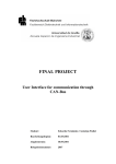
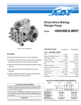
1.1. Fields of application
Objective of the VCI is to provide the user an uniform programming
interface for the different PC/CAN interface types of STZP. Neither the
version of the PC interface (DPRAM, LPT) nor the used CAN controller of
the interface are of importance. Besides VCI offers the possibility to run
simultaneously several (also various) boards.
Control
function
Monitor
function
CAN
Analyser
User
Application
Virtual CAN Interface
slot cards
iPCI 320/165
PCI 01/02
PC-Card
par. Port Adapter
tinCAN
CANdy
ser. Port Adapter
CANlink
CAN
The concept allows the realization of user programs independent of used
PC/CAN interface type.
9
Virtual CAN Interface
Introduction
By only linking an application program with the appropriate hardware
specific VCI library or VCI DLL the program can be adapted to different
PC/CAN interface types without any changes to the code. The universal
version of VCI allows the simultaneous support of all PC/CAN interface
types of STZP. This version also allows to use several PC/CAN interfaces
of different type at the same time.
A virtual CAN controller was defined in the VCI for providing a unique
functionality. Its structure corresponds with the basic CAN controller and
supports the operation with 11 bit and 29 bit identifiers. A firmware is used
to build this virtual CAN controller. It organizes the message
administration and provides the other functions listed below. The virtual
CAN controller can be available on a PC/CAN interface up to 4 times,
whereas a simultaneous usage of up to 4 boards is possible.
Active PC/CAN interfaces (with own memory and CPU) and passive
PC/CAN interface boards are supported by VCI. When interface boards
are used the PC is much more stressed because of the CAN controller
management and the reproduction of the virtual CAN controller.
Active PC/CAN interface boards support the PC in the processing of CAN
messages as well as in the data storage. This has a positive effect on the
processor load of the PC.
On the other hand passive PC/CAN interface boards allow the connection
of a PC to a CAN network at low costs, but this requires a high real time
performance of the PC (in Windows or OS/2 it is only useful at lower data
rates).
1.2. Importand remarks to the manual
The objective of this manual is to explain the concept of VCI and its
functions. It cannot be the sense of this manual to explain the problems of
programming CAN applications as well as the functionality of CAN
controllers.
This manual takes it for granted that the user is familiar with Borland-C or
Microsoft-C. Furthermore, it is required to know about interrupt handling
10
Virtual CAN Interface
Introduction
(as far as it is used) as well as about the programming of time-critical
applications. By using a VCI version for MS-Windows (3.11, 95, NT)
knowledge about program generation in MS-Windows is expected.
Before working with VCI you ought to have read this manual completely
at least once. This documentation was written deliberately in a short from
in order to hold the training expenditure as minor as possible. However,
the information is presented without much redundancy. A multiple work
through of this manual is therefore recommended, as very often important
information are not noticed when reading it the first time. In this
connection the study of the header file VCI.h is urgently recommended.
1.3. Installation of VCI
1.3.1. Installation of DOS-VCI
An EXE-file is located on the VCI disk. The file must be copied into the
destination directory of the PC for the installation. Then start the self
extracting file by using the option -d, for example:
PCM109BC -d
The files of VCI with the subdirectories are generated.
1.3.2. Installation of Windows-VCI (3.1, 95, NT)
There is a file ‘SETUP.EXE’ located in the disk(s). This file must be
started for installation.
The description of the files and additional information for the installation is
given in the file README2.TXT which is also on the disk.
11
Virtual CAN Interface
Introduction
1.3.3. Additional Hints for Installation
Additional information to the specific PC/CAN interface boards as well as
recent additions to the manual can be found in the subdirectory DOKU.
References for the installation of PC/CAN interface can be taken from the
supplied documents. Please make sure that the address and the interrupt
of the PC/CAN interface have not already been reserved by other boards
and the reserved address area of the PC/CAN interface is excluded in the
used memory manager (EMM386 or something).
When an active PC/CAN interface is used (with a local microcontroller
system) the firmware (VCI_nnnn.hex) must be loaded on to the PC/CAN
interface before the VCI can be used.
In DOS the download is performed with the download program of the
hardware (The provided batch file DLD.BAT calls DLOAD.EXE with the
necessary parameters for the used PC/CAN interface. If required
DLD.BAT has to be adapted to the used board address. Further
information about the parameters of the download program can be get by
starting DLOAD.EXE without any parameters).
In Windows 3.1/95/NT the firmware for the PC/CAN interface boards is
included in the VCI_XXX.DLL. When the application software or demo
program initializes the board with the function VCI_PrepareBoard the
firmware download is performed automatically (the automatic download
can also be disabled).
After the firmware download the delivered demo programs can be used
for first tests. When the demo program is started the board type and the
board location (or PC card slot) have to be specified as command line
arguments. Additional information to the parameters of a demo program
can be get when the program is started without arguments.
Of course, it is necessary to have the PC/CAN interface board connected
to at least a second operating CAN node in order to transmit or receive
messages.
12
Virtual CAN Interface
Introduction
1.4. Overview of VCI functionality
VCI supports the following functions:
•
Standard and extended protocol (11 and 29 bit identifiers).
•
Several CAN controllers per interface (as far as supported by the
hardware).
•
Simultaneous operation of up to four interfaces by one or more
applications (Windows version).
•
Supports baudrates up to 1000 kbaud.
•
Reception of messages via configurable receive queues (with ring
structure) including a time stamp or via configurable receive buffers
with a receive counter. Several queues and buffers can be assigned to
every CAN controller.
•
Transmission of messages via configurable queues. The queues may
have different priorities.
•
Queues can be polled or can be read using interrupts (interrupt
because of timeout or ´high level mark ´).
•
Automatic reply to remote objects is configurable.
•
VCI supplies statistical data about the CAN bus, CAN controller, the
data structures and the PC/CAN interfaces.
It must be noticed that there are restrictions concerning the functionslity of
the VCI depending on the used CAN controller:
• Philips 82C200:
no extended protocol
• Intel 82527:
no response to remote frames
• Philips SJA1000:
no restrictions
Depending on the functionality required for the application the CAN
controller must be selcetd.
13
Virtual CAN Interface
Introduction
The temporary storage of the received messages is done in the so-called
receive queues or receive buffers. In case of a queue the messages are
stored with a time stamp according to the time sequence of their receipt
(FIFO concept) and the messages can have different identifiers. In
comparison, a buffer stores only the message which was received as last
with a certain identifier (comparable to an actual process image) together
with a counter for the number of received CAN objects in this buffer.
The messages to be sent are written into transmit queues. The
microcontroller (only at intelligent PC/CAN interfaces) or an interrupt
function of the PC processes these messages. Furthermore remote
buffers can be configured, into which messages are stored that are not
directly transmitted. The data is transmitted only on request of another
network node.
The data structures for the message handling can have different sizes.
The memory available for this is restricted by the size of the on-board
memory (only at intelligent PC/CAN interfaces).
The hardware specific technical data of the VCI can be taken from the
appendix A.
1.5. Message management
In the following the elements are described which are provided by the VCI
for the handling of CAN messages (CAN objects).
1.5.1. Receive buffer
Receive buffers have to be created for every identifier to be received.
They always contain the data which is received as the latest in the chosen
identifier. Data which have not yet been read by the application is
overwritten by following data. The receive buffers have receive counters
for the flow control in case of repeated receptions. Receive buffers must
be checked by the application for the existence of new data.
14
Virtual CAN Interface
Introduction
An indication of received new data via an interrupt is not useful in this way
of data storage and therefore not implemented. Receive buffers are
usually used when the application checks the data only every one ina
while and is only interested in the actual data.
The maximum configurable number of receive buffers can be taken from
appendix A.
1.5.2. Receive queue
The use of receive queues is especially recommended for such
applications which have to accept all data being received by one ore more
identifiers and whenever the application program cannot react directly to
the receipt of an object.
The application program can specifiy how many objects and which
identifiers are stored in a certain queue. It is possible to install several
queues, so that a pre-sorting of CAN objects can already be done by the
microcontroller. All objects are stored in the receive queue with a time
stamp.
If a cyclic polling of the receive queue(s) is not useful or impossible
because of the structure of the application program an interrupt can be
signalled when an active PC/CAN interface is used. It is configurable
when the interrupt is signalled: if there is a special number of entries in a
queue (reaching of a ‘high level mark’) or after the expiry of a specified
time (timeout function).
The maximum configurable number of receive queues can be taken from
appendix A.
1.5.3. Transmit queue
The transmission of objects (data and data requests) from the application
is done via the transmit queues. Thus the application does not need to
wait for the CAN controller when requesting a transmission. The
processing of transmit queue(s) is done by the microcontroller of the
15
Virtual CAN Interface
Introduction
active PC/CAN interfaces or by the interrupt function of the PC regarding
passive PC/CAN interfaces.
Several queues of different size (number of objects) and of different
priority can be generated. The different priorities of the queues determine
in which order they are processed by the microcontroller.
The maximum configurable number of transmit queues can be taken from
the appendix A.
1.5.4. Remote buffer
Data which can be requested from other nodes by sending a remote
frame can be stored in remote buffers. In case of the reception of a
remote frame with the corresponding identifier the actual data is read from
the buffer and transmitted. The application only has to update the data in
the buffer. The processing of a remote frame is done with the highest
priority, that means before the transmit queues are processed.
Requests by remote frames can also be received via a receive queue. In
this case the application has to perform the transmission of the requested
data by writing an appropriate object into a transmit queue.
The maximum configurable number of remote buffers can be taken from
the appendix A.
16
Virtual CAN Interface
Interface description
2. Interface description
The VCI user interface provides a collection of functions to the user on
the PC. These functions have access to the PC/CAN interface and handle
the communication via CAN. The interface distinguishes between four
functional classes:
•
Functions for searching (base address), testing and configuring the
PC/CAN interfaces
•
Functions for the control and configuration of the VCI interface
•
Functions for the reception of messages
•
Functions for the transmission of messages.
The functions are described in the following. They are supplied as library
(DOS) or Windows-DLL. Supplied example programs show the use of the
functions.
2.1. Predefined return codes of VCI
In order to be able to support other PC/CAN interface types in the future,
and as it is impossible to specify all errors and return codes today which
can occur at coming implementations, all possible return codes are
described via the following defines. Additional information (error string
and further parameters) is supplied by the exception handler of the VCI
(Callback-function).
Define
Value error description
VCI_OK
1
Function executed successful
VCI_ERR
0
Standard error message, further specification via the exception handler.
VCI_QUE_EMPTY 0
The receive queue is empty, no messages
can be read.
17
Virtual CAN Interface
Interface description
VCI_QUE_FULL
0
The transmit queue is already full, no more
entries can be stored at the moment.
VCI_OLD
0
There is no new data in the receive buffer
anymore; if required old data will be read.
VCI_HWSW_ERR -1
Function could not be executed because of
hardware or software errors. Check the
function of the PC/CAN interface.
VCI_SUPP_ERR
-2
Function is not supported in this way
(support error). Check by means of the
overview of implementation to your platform.
VCI_PARA_ERR
-3
Passed parameters are wrong or outside the
valid range. Check the passed parameters.
VCI_RES_ERR
-4
Resource error. The resource limitations
(memory, maximum number of queues, etc.)
have been exceeded at the configuration of a
queue.
Check
by
means
of
the
implementation overview to your platform.
VCI_QUE_ERR
-5
An overrun occured at the referenced
receive queue. One or more messages could
therefore not be entered into the queue. The
position within the queue (where the
message loss took place) is specified by the
message status (VCI_CAN_OBJ.sts).
VCI_TX_ERR
-6
No message could be transmitted anymore
via CAN about a longer period of time (some
seconds). The reason could be a cable
break or a wrong baudrate. Check your CAN
connection.
If 'CciReqData-Error' is signalled in VCI_ERR as an error string of the
exception handler, then it is an error in the communication between PC
and PC/CAN interface. Possible errors are:
18
Virtual CAN Interface
Interface description
0
Command could not be passed to the PC/CAN interface.
1
The PC/CAN interface reply was an error instead of OK.
2
Wrong reply for the executed command.
3
A timeout occured while waiting for a reply.
4
The reply is too short (wrong length).
5
A timeout occured while passing a command to the PC/CAN
interface.
2.2. Type definitions of callback handler
Callback handlers are functions which are written by the user. They must
be get known to the system (VCI) by function pointers in
VCI_PrepareBoard() so that they can be called by the system. In the VCI
the callback functions serve to display and to handle errors, to process
interrupt messages and to print testing or initialization protocols.
The user is free in using these functions or to pass a NULL pointer
instead of a function pointer.
For example, if an interrupt is signalled by a receive queue the user has to
write an appropriate function (callback handler). This function must be
written for every installed PC/CAN interface which can signal interrupts.
2.2.1. Receive interrupt handler
The queue messages (timeout or ‘high level mark’) received by an
interrupt are passed to this function if it is configured with
VCI_ConfigQueue().
This callback handler is used for two different interrupt mechanisms:
1) Transmission of alarm objects
(max. 13 messages at once)
2) Signal of a receive queue for multitasking applications
19
Virtual CAN Interface
Interface description
In the first case the alarm objects are passed within the interrupt, in the
second case only a signal is passed to the user (count = 0).
Type definition: typedef void (*VCI_t_UsrRxIntHdlr) (UINT16
UINT16 count, VCI_CAN_OBJ far * p_obj);
que_hdl,
Typdefinition (Visual Basic 5+):
typedef void (*VCI_t_VB_UsrRxIntHdlr) (UINT16
que_hdl, UINT16 count, VCI_CAN_OBJ far * p_obj);
Parameters:
que_hdl (in)
Handle of the queue which has signalled the interrupt.
count (in)
Number of received objects.
p_obj (in)
FAR pointer to
VCI_CAN_OBJ.
Returnvalues:
the
received
object(s)
of
type
none
2.2.2. Exception handler
This function is called if there is an error in a system function. This error is
not only indicated via the return value, but is also passed to the exception
handler. Thus the user has two possibilities in handling errors. The
method via the exception handler allows a clearer program code.
Strings with a more precise error specification are passed to the exception
handler. The exception handler can print them into an error window or
write them into a file.
The zero terminated strings (without control characters) with a length of
60 characters maximum contain the function name of the function in
which the error occured and the error is specified much more precise.
An own exception handler must be written for each PC/CAN interface.
20
Virtual CAN Interface
Interface description
Type definition: typedef void (*VCI_t_UsrExcHdlr)(VCI_FUNC_NUM
func_num, int err_code, UINT16 ext_err, char * s );
Typdefinition (Visual Basic 5+):
typedef void (*VCI_t_VB_UsrExcHdlr)(
VCI_FUNC_NUM func_num,
int err_code,
UINT16 ext_err,
char * s );
Parameters:
func_num (in)
Specifies the function in which the error occurred. The
function is specified by the data content which is of the
enumeration type VCI_FUNC_NUM.
err_code (in)
Standard
error
codes,
specified
(VCI_SUPP_ERR, VCI_PARA_ERR, ...).
by
defines
ext_err (in)
Further error specifications in case of the standard error
code VCI_ERR (see below).
s (in)
Error string (max. 60 characters) with indication of the
function name as well as further error specification.
The evaluation of strings in Visual Basic 5+ is explained
in chapter ‘Special Hints for Visual Basic 5+’.
Returnvalues:
none
2.2.3. Handler for string output
For the functions VCI_TestBoard or VCI_PrepareBoard an output function
can be specified which can be used for printing a testing or initialization
protocol.
Zero terminated strings (without control characters) with a maximum
length of 60 characters are passed to this function.
21
Virtual CAN Interface
Interface description
Type definition: typedef void (*VCI_t_PutS)(char far * s);
Typdefinition (Visual Basic 5+):
typedef void (*VCI_t_VB_PutS)(char * s);
Parameter:
s (in)
Error string (max. 60 characters) with the indication of
the function name as well as further error specifications.
The evaluation of strings in Visual Basic 5+ is explained
in chapter ‘Special Hints for Visual Basic 5+’.
2.2.4. Special Hints for Visual Basic 5+
Visual Basic is able to process C strings (null terminated) correct when a
function from a DLL is called but when a Visual Basic callback function is
used a C string isn’t converted automatically to a Basic string. For this
reason an additional function was included in the VCI-DLL which is used
for copying of data (VCI_MemCopy). Using this function the Visual Basic
example ‘EXAMPLES\VisBas\CallBack\VCI_Demo’ of the VCI software
for Windows 95 and Windows NT shows how to convert C strings in
Basic strings (the callback functions are in ‘VCICallb.bas’).
22
Virtual CAN Interface
Interface description
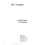
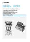
2.3. State diagram for the board initialization
undefined
VCI_Init
VCI
initialized,
no board
available
VCI_CancelBoard
VCI_SearchBoard
VCI_PrepareBoard
board
registered
and reset
VCI_TestBoard
VCI_ResetBoard
VCI_InitCan
CAN
controller
reset and
initialized
VCI_ResetCan
VCI_SetAccMask
VCI_StartCan
VCI_InitCan
CAN
controller
started
23
Virtual CAN Interface
Interface description
2.4. Initialization of VCI
2.4.1. VCI_Init
Function:
void VCI_Init(void);
Description:
Initialization of VCI structures (without any board
initialization). This function must be executed first.
Boards already initialized are reset and released
(handle is dropped).
Concerning the usage of this function in Windows
please refer to the chapter ‘Windows specific
extensions’.
Parameter:
none
Returnvalue:
none
2.5. Functions for VCI support information
2.5.1. VCI_Get_LibType (ab Vers. 1.09)
Function:
UINT32 VCI_Get_LibType();
Description:
‘VCI_Get_LibType’ returns the board types supported
by the VCI. Each bit position corresponds to the type
value which has to be used in VCI_PrepareBoard for
registering the selected board. Applications can use
this function e.g. for adapting dialog boxes.
Parameter:
none
24
Virtual CAN Interface
Returnwert:
Interface description
Bit field with 32 bit. Each position corresponds to a
specific board type. Several different board types can
be supported at the same time.
bit position
board type
0
iPC-I 165
1
iPC-I 320
2
CANdy
3
tinCAN
5
iPC-I 386
6
iPC-I 165 PCI
2.5.2. VCI_GetBrdNameByType (ab Vers. 1.09)
Function:
int VCI_GetBrdNameByType(
VCI_BOARD_TYPE boardtype,
char FAR* sz_boardname);
Description:
Returns the name in form of a string for the specified
board type (max. 20 characters).
Parameter:
boardtype (in)
VCI_IPCI320,
VCI_IPCI165,
VCI_CANDY,
VCI_PCMCIA, VCI_IPCI386, VCI_IPCI165_PCI, ....
sz_boardname (out)
Address of C string array whre the board type string is
copied: "CANdy", "tinCAN", "iPC-I 165", "iPC-I 320",
"iPC-I 386","iPC-I 165 PCI".
Return value:
0
<0
-> VCI_OK
-> VCI return codes
25
Virtual CAN Interface
Interface description
2.5.3. VCI_GetBrdTypeByName (ab Vers. 1.09)
Function:
int VCI_GetBrdTypeByName (
char FAR* sz_boardname);
Description:
Returns the type number of the board specified by the
gven board name (max. 20 characters).
Parameter:
sz_boardname (in)
Address of board type string (C string): "CANdy",
"tinCAN", "iPC-I 165", "iPC-I 320", "iPC-I 386","iPC-I
165 PCI".
Return value:
>0
-> board types:
VCI_IPCI320, VCI_IPCI165, VCI_CANDY,
VCI_PCMCIA, VCI_IPCI386,
VCI_IPCI165_PCI, ....
-> VCI return codes
<0
2.6. Functions for board initialization
2.6.1. VCI_SearchBoard
Function:
int VCI_SearchBoard(VCI_BOARD_TYPE
board_type, UINT8 * p_int_num, UINT16 *
p_board_seg);
Description:
An interface with the given interface type will be
searched starting from the address given by the pointer
p_board_seg.
!
26
This function is only implemented for supporting
the installation of a board. Using this function
for other purposes can cause failures on the
computer because during the search memory
areas might be accessed which are in use by
other programs.
!
Virtual CAN Interface
Interface description
Possible addresses of PC/CAN interfaces
PC/CAN Interface
Address
Slot ISA PC/CANInterfaces
C000 - FE00
PC Card tinCAN
Socket-No. 0 - 3
LPT Adapter
CANdy
Number of parallel
interface: 1, 2
In p_board_seg also a pointer is returned with the
address of the first PC/CAN interface (VCI_OK) which
is found. If another interface is to be searched,
*p_board_seg must be increased for another search. If
VCI_ERR is returned no PC/CAN interface of the given
type was found.
The PC/CAN interface is reset when the search is
executed. This means that all PC/CAN interfaces which
have already been set into operation mode are reset
again as far as the search starts at the first address.
Parameter:
board_type (in)
VCI_IPCI320, VCI_IPCI165, VCI_CANDY,
VCI_PCMCIA, VCI_PCI,....
p_board_seg (in/out)
Pointer to address segment, Pc card slot number or the
LPT number where the search shall start.
p_int_num (in/out)
Pointer to the used interrupt of the board
(0 -> interrupt is searched).
Return value:
VCI return codes.
27
Virtual CAN Interface
Interface description
2.6.1. VCI_SetDownloadState (from vers. 1.09)
Function:
void VCI_SetDownloadState (BOOL o_dld_on);
Beschreibung:
The VCI from version 1.09 on supports an automatic
download of the VCI firmwware to the interface board.
In certain cases it may be useful not to perform the
automatic download. This mode is set when
VCI_SetDoanloadState() is called with o_dld_on =
FALSE. Then all further calls of ‘VCI_PrepareBoard’
are processed without firmware download.
Parameter:
o_dld_on (in)
switches
automatic
download
mode
in
‘VCI_PrepareBoard’ on or off. Default is set to on:
TRUE -> automatic download wird on
FALSE -> automatic download wird off
Returnwert:
none
2.6.2. VCI_PrepareBoard
Function:
int VCI_PrepareBoard(VCI_BOARD_TYPE
board_type, UINT16 board_seg, UINT8 irq_num,
VCI_t_PutS fp_puts, VCI_t_UsrIntHdlr fp_int_hdlr,
VCI_t_UsrExHdlr fp_exc_hdlr);
Description:
Register the given interface in the VCI. This includes
resetting the interface, download of the firmware (only
in Windows versions) and starting the firmware on
intelligent interfaces. A handle is returned to the
PC/CAN interface by which the interface can be
addressed. Handles are given as ascending numbers
from zero on (0,1,2,...n).
28
Virtual CAN Interface
Interface description
If zero is stated as IRQ-number so VCI works without
interrupt as far as it is supported by the PC/CAN
interface. The function VCI_ConfigQueue with interrupt
mode cannot be used.
The function VCI_PrepareBoard must be executed
before the interface is accessed (exception:
VCI_SearchBoard). Interfaces already registered and
therefore assigned to a program cannot be registered
again. (If the PC/CAN interface is to be used by
another application the interface must be released via
VCI_CancelBoard before.)
The callback handlers
VCI_PrepareBoard.
are
also
set
with
- PutString for the screen output in PrepareBoard.
- Exception handler for error handling.
- Receive interrupt handler for the interrupt handling.
See type definitions of the callback handlers.
29
Virtual CAN Interface
Parameter:
Interface description
board_type (in)
VCI_IPCI320, VCI_IPCI165, VCI_CANDY,
VCI_PCMCIA, VCI_PCI,....
board_seg (in)
Adress segment / LPT number / COM number of
PC/CAN Interface.
irq_num (in)
IRQ-number of the interface. If the interface shall be
used without interrupt the value must be zero.
fp_puts
Callback function for the output of error and status
detection during prepare board
(NULL -> no status output).
fp_int_hdlr
Function pointer to the interrupt function for processing
of receive objects.
(NULL -> no interrupt processing)
fp_exc_hdlr
Function pointer to exception handler for processing of
occured errors.
(NULL -> no exception handler)
Return value:
>= 0
<0
-> Board handle
-> VCI return codes.
2.6.3. VCI_PrepareBoardMsg (Windows 3.1)
Function:
30
int VCI_PrepareBoardMsg
( VCI_BOARD_TYPE board_type
, UINT16 board_seg
, UINT8 irq_num
, VCI_t_PutS fp_puts
Virtual CAN Interface
Interface description
, UINT msg_int_hdlr,
VCI_t_UsrExcHdlr fp_exc_hdlr,
HWND apl_handle);
Description:
In Windows interrupts can be processed conventional
using callback functions or using a message handler.
Therefore the DLL provides an ISR which mainly
concentrates on sending a message for informing the
application that an interrupt has occurred.
With this function a Windows Message Identifier
('msg_int_hdlr') and a Windows Handle ('apl_handle')
is passed to the interrupt mechanism of the VCI-DLL
instead of a callback function.
The following parameters are passed with the Windows
message to the application referenced by the Windows
handle:
WPARAMcount
(Number of CAN objects, which are passed with the
message)
LPARAM Pointer to passed data
1. BYTE QueRef
(references the queue which initiated the interrupt)
2. ...n. BYTE CAN_OBJ
(the received data in form of type VCI_CAN_OBJ)
Example.:
void Int_Msg_handler(UINT16 WPARAM,UINT 32
LPARAM)
{
UINT 16 count = WPARAM;
UINT 8 * temp, QueRef;
temp = (UINT 8*) LPARAM;
VCI_CAN OBJ CAN_OBJ[20];
QueRef = temp[0];
31
Virtual CAN Interface
Interface description
memcpy(CAN_OBJ,(VCI_CAN_OBJ *) &temp[1],
count*sizeof(VCI_CAN OBJ));
}
Please refer
information.
to
VCI_PrepareBoard
for
further
2.6.4. VCI_PrepareBoardVisBas (Visual Basic 5+, VCI V 1.09)
Function:
int VCI_PrepareBoardVisBas(VCI_BOARD_TYPE
board_type, UINT16 board_seg, UINT8 irq_num,
VCI_t_VB_PutS fp_puts,
VCI_t_VB_UsrIntHdlr fp_int_hdlr,
VCI_t_VB_UsrExHdlr fp_exc_hdlr);
Description:
This PrepareBoard function is to be used with Visual
Basic from version 5. In this version callback handlers
can be used. Because these callbacks have a different
calling convention than the callback handlers of the
standard VCI_PrepareBoard new types have beed
defined. Otherwise the function is equal to
VCI_PrepareBoard.
Please refer
information.
32
to
VCI_PrepareBoard
for
further
Virtual CAN Interface
Interface description
2.6.5. VCI_CancelBoard
Function:
int VCI_CancelBoard(UINT16 board_hdl);
Description:
The registered board is released in the VCI. This
includes the reset of the interface and the CAN
controllers as well as the deinstallation of the used
interrupts. The board handle is also released.
Parameter:
board_hdl (in)
Handle of a board registered before.
Return value:
VCI return codes.
2.6.6. VCI_TestBoard
Function:
UINT8 VCI_TestBoard(UINT16 board_hdl,
VCI_t_PutS fp_puts);
Description:
The specified board executes a self-test. This is done
by a test routine integrated in the firmware. The test
protocol is printed using the callback handler fp_puts
and the result of the test is returned by the return value.
See type definitions of the callback handler.
Parameter:
board_hdl (in)
Handle of the board registered before.
fp_puts
Callback function for printing the test protocols during
the test of the interface (NULL -> no protocol output).
Return value:
VCI return codes.
33
Virtual CAN Interface
Interface description
2.6.7. VCI_ReadBoardInfo
Function:
int VCI_ReadBoardInfo(UINT16 board_hdl ,
VCI_BOARD_INFO * p_info);
Description:
Reads the board information according to
VCI_BOARD_INFO:
~.hw_version
~.fw_version
~.dd_version
~.sw_version
~.can_num
Hardware version as HEX value (i.e: 0x0100 for V1.00),
Firmware version as HEX value,
Device driver version as HEX value (only for PC card),
Version number of PC software as HEX value,
Number of CAN controllers supported by the board,
~.time_stamp_res Smallest resolution of the time stamp,
~.timeout_res
Smallest resolution of the timeout (receive queues),
~.mem_pool_size Size of the memory pool which is used for the
installation of queues and buffers,
~.irq_num
Interrupt number for the communication with the
PC/CAN interface,
~.board_seg
Configured board address/segment/port number,
~.serial_num
16 characters string with the serial number of the
board,
~.str_hw_type
terminated string with hardware identification.
The values for the smallest time stamp or timeout resolution depend on
the used type of interface board and can be used to select a meaningful
value for these timers in the application.
The use of this function is optional and serves for the specification of the
PC/CAN interface only. The information can also be taken from the
overview of the implementation in the appendix.
Parameter:
board_hdl (in)
Handle of the board registered before.
p_info (out)
Pointer on the info data.
Return value:
34
VCI return codes.
Virtual CAN Interface
Interface description
2.6.8. VCI_ReadBoardStatus
Function:
int VCI_ReadBoardStatus(UINT16 board_hdl,
VCI_BRD_STS * p_sts);
Description:
Reading of the board information according to
VCI_BRD_STS:
~.sts
Bit coded information of the board status:
Bit 0:
RxQueue overrun; an overrun occured in a
configured receive queue (queue was already full and
another message could not be entered). Further
information can be obtained with VCI_ReadQueStatus
and VCI_ReadQueObj.
Bit 4:
CAN0-Running
Bit 5:
CAN1-Running
Bit 6:
CAN2-Running
Bit 7:
CAN3-Running
Status bits of the CAN controllers on the board ( up to 4
CAN controllers maximum per board are supported by
the VCI).
Initialized, started and correctly working CAN
controllers are set to ´1´. If the CAN controller is in busoff status or init mode or if a CAN data overrun or
remote queue overrun occured then the bit is set to ´0´.
The exact reason must then be determined with
VCI_ReadCanStatus.
This function allows to get a fast overview about the
actual states of the CAN controllers.
average CPU load in % (0-100).
~.cpu_load
Parameter:
board_hdl (in)
Handle of the board registered before.
p_sts (out)
Pointer to the status to be read.
Return value:
VCI return codes.
35
Virtual CAN Interface
Interface description
2.6.9. VCI_ResetBoard
Function:
int VCI_ResetBoard(UINT16 board_hdl );
Description:
Reset of the interface (soft- and hardware). The board
keeps registered, but the communication is interrupted
by this. After the execution of this function the board as
well as the CAN controllers must be reinitialized again.
Parameter:
board_hdl (in)
Handle of the board registerred before.
Return value:
VCI return codes.
2.7. Functions for CAN initialization
2.7.1. VCI_ReadCanInfo
Function:
int VCI_ReadCanInfo( UINT16 board_hdl, UINT8
can_num , VCI_CAN_INFO * p_info);
Description:
Reading of the CAN controller type as well as of the
configured parameters according to VCI_CAN_INFO:
~.can_type
Type of the CAN controller according to
VCI_CAN_TYPE,
configured value for the Bit Timing Register 0.
configured value for the Bit Timing Register 1.
configured value for the Acceptance Code Register.
configured value for the Acceptance Mask Register.
~.bt0
~.bt1
~.acc_code
~.acc_mask
Parameter:
36
board_hdl (in)
Handle of the board registered before.
Virtual CAN Interface
Interface description
can_num (in)
Number of the CAN controller (0..3).
p_info (out)
Pointer to info data.
Return value:
VCI return codes.
2.7.2. VCI_ReadCanStatus
Function:
int VCI_ReadCanStatus( UINT16 board_hdl, UINT8
can_num , VCI_CAN_STS * p_sts);
Description:
Reading of the status information of the referenced
CAN controller and of the assigned software according
to VCI_CAN_STS:
~.sts
Bit coded information of the CAN status (1 = true):
Bit 0: not used,
Bit 1: not used,
Bit 2: RemoteQueueOverrun - An overrun occured in
the internal queue used for processing of remote
requests.
Bit 3: CAN-TX-Pending - A transmission operation is
just running. If this status lasts without
transmitting new data then the CAN controller is
not able to send the data (cable break or
something similar)
Bit 4: CAN-Init-Mode - CAN is in the initialization
mode and can be set in running mode with
VCI_StartCan,
Bit 5: CAN-Data-Overrun - An overrun of CAN
messages occured in the CAN controller (or in
the software of the CAN controller),
37
Virtual CAN Interface
~.bus_load
Interface description
Bit 6: CAN-Error-Warning-Level - The CAN controller
entered the error warning level because of
defects on the bus,
Bit 7: CAN-Bus-Off-Status, - The CAN controller has
switched off itself totally from the bus because of
bus defects.
Reserved, not supported function.
Bits 4 - 7 are directly read from the status registers of
the CAN controllers. (Further information referring
these bits can be taken from the data sheets of the
CAN controllers Phillips 82C200 or Intel 82527).
If there is an error in the CAN controller (Bit 2,5 and 7),
then this status can only be left by executing the
function VCI_ResetCan.
Parameter:
board_hdl (in)
Handle of the board resgistered before.
can_num (in)
Number of the CAN controller (0..n).
p_sts (out)
Pointer to status data.
Return value:
VCI return codes.
2.7.3. VCI_InitCan
Function:
int VCI_InitCan( UINT16 board_hdl, UINT8 can_num,
UINT8 bt0, UINT8 bt1, UINT8 mode);
Description:
Initialization of the bus timing registers. The values are
according to the data sheet of Philips 80C200. The
values are converted for other controllers.
The referenced CAN controller is set into the init mode
38
Virtual CAN Interface
Interface description
for this purpose and must then be restarted with
VCI_StartCan.
Parameter:
board_hdl (in)
Handle of the board registered before.
can_num (in)
Number of the CAN controller (0..3).
bt0 (in)
Value for bit timing register 0.
bt1 (in)
Value for bit timing register 1.
mode (in)
11bit / 29 bit mode (VCI_11B, VCI_29B).
Return value:
VCI return codes.
The values for 'bt0' and 'bt1' for the usually used baud rates (16MHz
clock at the CAN controller) are listed in the following table:
Baud rate in kbit/s
bt0
bt1
1000
00h
14h
500
00h
1Ch
250
01h
1Ch
125
03h
1Ch
100
43
2Fh
50
47h
2Fh
20
53h
2Fh
10
67h
2Fh
39
Virtual CAN Interface
Interface description
2.7.4. VCI_SetAccMask
Function:
int VCI_SetAccMask( UINT16 board_hdl, UINT8
can_num, UINT32 acc_code, UINT32 acc_mask );
Description:
Setting of the acceptance mask registers of the CAN
controller for a global object filtering in the 11 bit or 29
bit mode (this controller specific function is done in
software if requried). The filter uses all identifer bits.
The acceptance filter is totally open (0x0UL, 0x0UL), as
long as this function is not executed. The referenced
CAN controller is set into the init mode and must then
be restarted with VCI_StartCan.
With the variables acc_code and acc_mask single
CAN-IDs or whole ID groups can be defined.
Examples:
1.) Only CAN-ID 100 shall be received:
acc_code = 100 and acc_mask = 0xffffffff
0xffffffff -> all bits of acc_code are relevant
2.) The CAN-IDs 100-103 shall be received:
acc_code = 100 und acc_mask = 0xfffffffc
0xfffffffc -> all bits of acc_code are relevant except the
two lowest (00,01,10,11).
Parameter:
board_hdl (in)
Handle of the board registered before.
can_num (in)
Number of the CAN controller (0..3).
acc_code (in)
Value for the acceptance code register
acc_mask (in)
Value for the acceptance mask register
(0 - don't care; 1 - relevant)
40
Virtual CAN Interface
Return value:
Interface description
VCI return codes.
2.7.5. VCI_ResetCan
Function:
int VCI_ResetCan( UINT16 board_hdl, UINT8
can_num );
Description:
This function resets the CAN controller and stopps the
communication via the referenced CAN controller. Also
the status register is reset with this function and the
queues and buffers which are assigned to this CAN
controller are reinitialized.
The CAN controller does not lose its configuration and
can be started again with VCI_StartCan.
Parameter:
board_hdl (in)
Handle of the board registered before.
can_num (in)
Number of the CAN controller (0..3).
Return value:
VCI return codes.
2.7.6. VCI_StartCan
Function:
int VCI_StartCan( UINT16 board_hdl,
UINT8 can_num );
Description:
Starts the referenced CAN controller
Parameter:
board_hdl (in)
Handle of the board regsistered before.
can_num (in)
Number of the CAN controller (0..3).
Return value:
VCI return codes.
41
Virtual CAN Interface
Interface description
2.8. Functions for the VCI configuration
2.8.1. VCI_ConfigQueue
Function:
Description:
UINT16 VCI_ConfigQueue( UINT16 board_hdl, UINT8
can_num, UINT8 que_type, UINT16 que_size, UINT16
int_limit, UINT16 int_time, UINT16 ts_res, UINT16 *
p_que_hdl);
Installation of a transmit or receive queue. The returned
handle references the queue and can be used to access
the queue. Handles are given as ascending numbers:
Receive queues: 0, 1, 2, ...
Transmit queues: 256, 257, 258, ...
Following in case of a receive queue all desired CAN
objects
must
be
registered
using
‘VCI_AssignRxQueObj’.
There are 3 different modes for processing of queue
messages in receive queues:
1)
Installation of a queue using polling mode with
VCI_ReadQueObj. The parameters int_limit and
int_time must be set to zero. (normal operation
mode in DOS)
2)
Installation of a queue using interrupt processing
of alarm objects. Useful values for this are 1 for
int_limit and zero for int_time (max. 13 objects).
With these settings the alarm object(s) are passed
directly to the interrupt callback handler (passed
with VCI_PrepareBoard). In this mode the queue
cannot be read with ReadQueObj.
!
42
'VCI_ReadQueObj()' can’t be used in this
case.
!
Virtual CAN Interface
3)
Interface description
Installation of a queue using event mode. Here the
interrupt signal can be used for starting an
assigned task in a multitasking environment.
Int_limit must be set >13 and int_time must be set
to a value bigger than zero. The queue can then
be read with VCI_ReadQueObj (max. 13 objects at
once).
The callback handler is described more detailed in
chapter ‘Receive-Interrupt-Handler’.
The values of the timing parameters must be within the
ranges supported by the used interface (see appendix A).
The CAN controller which is assigned to the queue must
be in the init mode for the configuration of the queues !!
Parameter:
board_hdl (in)
Handle of the board registered before.
can_num (in)
Number of the CAN controller (0..3).
que_type (in)
Queue type (VCI_TX_QUE, VCI_RX_QUE).
que_size (in)
Size of the queue in number of CAN objects (must be
>= 20 !)
int_limit (in)
Specifies the number of received CAN objects which
are stored in the queue until an interrupt is signalled.
0 = no signalling of an interrupt.
<=13:
received objects are immediately
passed with an interrupt
>13:
received objects must be read from the
queue using the function
'VCI_ReadQueObj()' .
43
Virtual CAN Interface
Interface description
int_time (in)
Specifies the time in milliseconds after which an
interrupt is signalled if 'int_limit' is not reached.
0 = do not signal any interrupts.
This value must be set if ´int_limit´ is > 0, otherwise
single CAN messages can „starve“ in the receive
queue.
According to the size of 'int_limit' the CAN objects are
passed directly within the interrupt or must be polled.
ts_res (in)
Resolution in µs of the objects time stamps in the
receive queue.
p_que_hdl (out)
Handle of the queue.
Return value:
VCI return codes.
2.8.2. VCI_AssignRxQueObj
Function:
int VCI_AssignRxQueObj(UINT16 board_hdl, UINT16
que_hdl, UINT8 mode, UINT32 id,
UINT32 mask);
Description:
Configures the referenced receive queue to receive or
reject CAN objects. Identifier groups can be defined
directly via the mask.
Attention: In the 29 bit mode it is not possible to define
any many identifiers as you like. Different acceptance
filter mechanisms are used according to the used
interface type. Therefore, the number of filters which
can be defined is limited (see appendix A).
The usage of ‘id’
‘VCI_SetAccMask’.
44
and
‘mask’
is
explained
in
Virtual CAN Interface
Interface description
The CAN controller which is assigned to the queue must
be in Init-Mode during the configuration of the queue !!
Parameter:
board_hdl (in)
Handle of the board registered before.
que_hdl (in)
Queue handle.
mode (in)
Assign or reject the specified object(s)
(VCI_ACCEPT, VCI_REJECT).
id (in)
Identifier of the object(s).
mask (in)
Mask for the specification of the relevant identifier bits.
(0 - don't care; 1 - relevant)
Return value:
VCI return codes.
2.8.3. VCI_ResetTimeStamp
Function:
int VCI_ResetTimeStamp( UINT16 board_hdl );
Description:
Resets the timer used for the time stamps of the
receive queues.
Parameter:
board_hdl (in)
Handle of the board registered before.
Return value:
VCI return codes.
45
Virtual CAN Interface
Interface description
2.8.4. VCI_ConfigBuffer
Function:
int VCI_ConfigBuffer( UINT16 board_hdl, UINT8
can_num, UINT8 type, UINT32 id, UINT16 *
p_buf_hdl);
Description:
Installs a receive or remote buffer. The returned handle
references the buffer and can be used to access the
buffer. Handles are given as ascending numbers from
zero on (0,1,2,...n).
Parameter:
board_hdl (in)
Handle of the board registered before.
can_num (in)
Number of the CAN controller (0..n).
type (in)
Receive or remote buffer
(VCI_RX_BUF, VCI_RMT_BUF).
id (in)
Identifier which is assigned to the buffer.
p_buf_hdl (out)
Handle of the buffer.
Return value:
VCI return codes.
2.8.5. VCI_ReConfigBuffer
Function:
int VCI_ReConfigBuffer( UINT16 board_hdl, UINT16
buf_hdl, UINT8 type, UINT32 id);
Description:
Used to change the identifier of a receive or remote
buffer. The buffer is accessed by the handle.
46
Virtual CAN Interface
Parameter:
Interface description
board_hdl (in)
Handle of the board registered before.
buf_hdl (in)
Handle of the buffer.
type (in)
Receive or remote buffer
(VCI_RX_BUF, VCI_RMT_BUF).
id (in)
Identifier assigned to the buffer.
Return value:
VCI return codes.
2.9. Reception of messages
2.9.1. VCI_ReadQueStatus
Function:
int VCI_ReadQueStatus(UINT16 board_hdl,
UINT16 que_hdl);
Description:
Reads the status of the referenced queue.
Parameter:
board_hdl (in)
Handle of the board registered before.
que_hdl (in)
Handle of the queue.
Return value:
>0 Number of queue entries.
=0 Queue empty (VCI_QUE_EMPTY),
<0 VCI return codes.
47
Virtual CAN Interface
Interface description
2.9.2. VCI_ReadQueObj
Function:
int VCI_ReadQueObj( UINT16 board_hdl, UINT16
que_hdl, UINT16 count, VCI_CAN_OBJ * p_obj);
Description:
Reads the first entry(ies) of a receive queue. The
number of entries to be read are given in ´count´. Only
as many entries as available in the queue or supported
by the interface are read. This means that the queue
has to be read until the value VCI_QUE_EMPTY is
returned.
If the status byte of the message returns 0x80 =
Queue-Overrun, no further message could be stored in
the queue after this message. -> loss of data !
Parameter:
board_hdl (in)
Handle of the board registered before.
que_hdl (in)
Handle of the queue.
count (in)
Maximum number of objects which shall be read. (max
= 13)
p_obj (out)
Pointer to the object(s) to be read.
Return value:
>0 Number of read queue entries.
=0 Queue empty (VCI_QUE_EMPTY).
<0 VCI return codes.
2.9.3. VCI_ReadBufStatus
Function:
48
int VCI_ReadBufStatus( UINT16 board_hdl,
UINT16 buf_hdl);
Virtual CAN Interface
Interface description
Description:
Reads the buffer status without changing it. The buffer
status is the number of received objects in this buffer
since the last reading of the data.
Parameter:
board_hdl (in)
Handle of the board registered before.
buf_hdl (in)
Handle of the buffer.
Return value:
=0 no new data (VCI_OLD).
>0 Number how often objects were received after the
last reading.
<0 VCI return codes.
2.9.4. VCI_ReadBufData
Function:
int VCI_ReadBufData( UINT16 board_hdl,
UINT16 buf_hdl, UINT8 * p_data, UINT8 * p_len);
Description:
Reads the data in the buffer and resets the buffer
status. The status (number of receive processes since
the last reading) is returned. If this value is added up,
the result is the absolute number of received objects
since the program start.
Parameter:
board_hdl (in)
Handle of the board registered before.
buf_hdl (in)
Handle of the buffer.
p_data (out)
Pointer to the data to be read.
p_len (out)
Pointer to the number of the data bytes.
49
Virtual CAN Interface
Return value:
Interface description
=0 no new data (VCI_OLD).
>0 Number how often objects were received after the
last reading.
<0 VCI return codes.
2.10. Transmission of messages
2.10.1. VCI_TransmitObj
Function:
int VCI_TransmitObj( UINT16 board_hdl,
UINT16 que_hdl, UINT32 id, UINT8 len,
UINT8 * p_data);
Description:
Transmits a data object via the referenced transmit
queue. If VCI_QUE_FULL is returned the referenced
transmit queue is actually full and the transmit request
must be repeated (later). If VCI_TX_ERR is returned
then the CAN controller cannot transmit messages
because of cable break or wrong baudrate.
Parameter:
board_hdl (in)
Handle of the board registered before.
que_hdl (in)
Handle of the queue.
id (in)
Identifier of the transmit object.
len (in)
Number of data bytes.
p_data (in)
Pointer to the data to be transmitted.
Return value:
50
VCI return codes.
Virtual CAN Interface
Interface description
2.10.2. VCI_RequestObj
Function:
int VCI_RequestObj( UINT16 board_hdl,
UINT16 que_hdl, UINT32 id, UINT8 len );
Description:
Transmits a remote object via the referenced transmit
queue. If VCI_QUE_FULL is returned the referenced
transmit queue is actually full and the transmitting order
must be repeated (later). If VCI_TX_ERR is returned
the CAN controller cannot transmit messages because
of cable break or wrong baudrate.
Parameter:
board_hdl (in)
Handle of the board registered before.
que_hdl (in)
Handle of the queue.
id (in)
Identifier of the transmit object.
len (in)
Number of data bytes.
Return value:
VCI return codes.
2.10.3. VCI_UpdateBufObj
Function:
int VCI_UpdateBufObj( UINT16 board_hdl,
UINT16 buf_hdl, UINT8 len, UINT8 * p_data );
Description:
Updates data in a remote buffer which can be
requested via the CAN network by another node.
51
Virtual CAN Interface
Parameter:
Interface description
board_hdl (in)
Handle of the board registered before.
buf_hdl (in)
Handle of the buffer.
len (in)
Number of data bytes.
p_data (in)
Pointer to the data.
Return value:
52
VCI_OK, VCI_QUE_ERR, VCI_HWSW_ERR,
VCI_SUPP_ERR, VCI_PARA_ERR.
Virtual CAN Interface
Interface description
2.11. Used data types
Please take the exact specification of the used data types from the file
VCI.H. In the following the most important structures are explained.
2.11.1. VCI-CAN-Object
The transmission of CAN messages via transmit queues and the reading
of CAN messages from the receive queues is done using the data
structure VCI_CAN_OBJ:
~.time_stamp
Time stamp for receive queue messages. The
resolution is set with the function VCI_ConfigQueue.
Please notice that an overrun (> 12 hours) occurs after
(2 ^ 32 * TimeStampResolution) independent of the
format of the time stamp. The time stamp can be set to
zero again with the function VCI_ResetTimeStamp.
~.id
11/29 bit identifier of the CAN message (always rightjustified).
~.len
Number of data bytes of the CAN message (0-8 bytes).
~.rtr
1 = remote request (data request message); the
following data bytes have no meaning;
0 = normal CAN message.
~.res
not used
~.a_data[8]
Array of 8 bytes for storing the data bytes of the
message.
~.sts
Status of the message: 0 = OK; 0x80 = Queue overrun
(After this message no further message can be stored
in the receive queue because it was already full. ->
data loss !!!)
53
Virtual CAN Interface
Interface description
2.11.2. VCI-Board-Information
The reading of the board information is done using the data structure
VCI_BOARD_INFO:
~.hw_version
~.fw_version
~.dd_version
~.sw_version
~.can_num
Hardware version as HEX value (i.e: 0x0100 for V1.00),
Firmware version as HEX value,
Device driver version as HEX value (only for PC card),
Version number of PC software as HEX value,
Number of CAN controllers supported by the board,
~.time_stamp_res Minimum resolution of the time stamp provided by the
board,
~.timeout_res
Minimum resolution of the timeout used for the receive
queues provided by the board,
~.mem_pool_size Size of the memory pool which is used for the
installation of queues and buffers,
~.irq_num
Interrupt number for the communication with the
PC/CAN interface,
~.board_seg
Configured board address/segment/port number,
~.serial_num
16 characters string with the serial number of the
board,
~.str_hw_type
terminated string with hardware identification.
2.11.3. VCI-Board-Status
The reading of the board status is done using the data structure
VCI_BRD_STS:
~.sts
54
Bit coded information of the board status:
Bit 0:
RxQueue overrun; an overrun occured in a
configured receive queue (queue was already full and
another message could not be entered). Further
information can be obtained with VCI_ReadQueStatus
and VCI_ReadQueObj.
Bit 4:
CAN0-Running
Bit 5:
CAN1-Running
Bit 6:
CAN2-Running
Bit 7:
CAN3-Running
Virtual CAN Interface
~.cpu_load
Interface description
Status bits of the CAN controllers on the board ( up to 4
CAN controllers maximum per board are supported by
the VCI).
Initialized, started and correctly working CAN
controllers are set to ´1´. If the CAN controller is in busoff status or init mode or if a CAN data overrun or
remote queue overrun occured then the bit is set to ´0´.
The exact reason must then be determined with
VCI_ReadCanStatus.
This function allows to get a fast overview about the
actual states of the CAN controllers.
average CPU load in % (0-100).
2.11.4. VCI-CAN-Information
The reading of CAN information is done using the data structure
VCI_CAN_INFO:
~.can_type
~.bt0
~.bt1
~.acc_code
~.acc_mask
Type of the CAN controller according
VCI_CAN_TYPE,
configured value for bit timing register 0.
configured value for bit timing register 1.
configured value for acceptance code register.
configured value for acceptance mask register.
to
2.11.5. VCI-CAN-Status
The reading of the CAN status is done using the data structure
VCI_CAN_STS:
~.sts
Bit coded information of the CAN status (1 = true):
Bit 0: not used,
Bit 1: not used,
Bit 2: RemoteQueueOverrun - An overrun occured in
the internal queue used for the processing of
remote requests.
Bit 3: CAN-TX-Pending - A transmission operation is
just running. If this status lasts without
55
Virtual CAN Interface
~.bus_load
Interface description
transmitting new data then the CAN controller is
not able to send the data (cable break or
something similar)
Bit 4: CAN-Init-Mode - CAN is in the initialization
mode and can be set in running mode with
VCI_StartCan,
Bit 5: CAN-Data-Overrun - An overrun of CAN
messages occured in the CAN controller (or in
the software of the CAN controller),
Bit 6: CAN-Error-Warning-Level - The CAN controller
entered the error warning level because of the
defects on the bus,
Bit 7: CAN-Bus-Off-Status, - The CAN controller has
switched off itself totally from the bus because of
bus defects.
Reserved, not supported function.
Bits 4 - 7 are directly read from the status registers of
the CAN controllers. (Further information referring
these bits can be taken from the data sheets of the
CAN controllers Phillips 82C200 or Intel 82527).
If there is an error in the CAN controller (Bit 2,5 and 7),
then this status can only be left executing the function
VCI_ResetCan.
56
Virtual CAN Interface
Windows-specific extensions (DLL)
3. Windows-specific extensions (DLL)
The Windows version of the Virtual CAN Interface in form of a Dynamic
Link Library (DLL) has some differences compared to the DOS version.
•
The DLL is not linked like a normal C-library, but is loaded during run
time by the application and is dynamically connected with it. The
functions of DLL are located therefore in an own compiler module and
must be linked in a special way. The linking is explained in paragraph
3.1.
•
The function VCI_Init() is called in Windows from within the 'VCI-DLL'
and can therefore not be called by an application. For the program
development in an interpreter environment it may be useful to reset the
DLL explicitly with VCI_Init(). This shouldn’t be used in the release
version of the application. Here ‘VCI_CancelBoard’ has to be used.
•
In Windows the callback handler functions should be declared with the
'_loadds' instruction or should be passed like other callback functions
with GetProcInstance().
•
Besides the conventional way using a callback function for processing
interrupt requests, they can also be processed using a message
handler.
Therefore an ISR is already located in VCI-DLL. The only function of
the ISR is to inform the application by a message that an interrupt has
occured.
For configuring the message an additional function was necessary
int VCI_PrepareBoardMsg
( VCI_BOARD_TYPE board_type
, UINT16 board_seg
, UINT8 irq_num
, VCI_t_PutS fp_puts
, UINT msg_int_hdlr,
VCI_t_UsrExcHdlr fp_exc_hdlr,
HWND apl_handle).
57
Virtual CAN Interface
Windows-specific extensions (DLL)
Instead of passing a callback function for processing the interrupt to
the VCI-DLL a Windows message identifier ('msg_int_hdlr') and a
Windows handle ('apl_handle') are passed with this function to the
VCI-DLL.
The application which is referenced by the Windows handle receives
the following parameters from the Windows message.
WPARAM
count
(Number of CAN objects which are passed with the
message)
LPARAM
Pointer
to
the
transmitted
data
1. BYTE QueRef
(references the queue which has signalled the interrupt)
2..n.BYTE CAN_OBJ
(the number of CAN_OBj of the type VCI_CAN_OBJ)
given by ´count´)
Example:
void Int_Msg_handler(UINT16 WPARAM,UINT 32
LPARAM)
{
UINT 16 count = WPARAM;
UINT 8 * temp, QueRef;
temp = (UINT 8*) LPARAM;
VCI_CAN OBJ CAN_OBJ[20];
QueRef = temp[0];
memcpy(CAN_OBJ,(VCI_CAN_OBJ *) &temp[1],
count*sizeof(VCI_CAN OBJ));
}
58
Virtual CAN Interface
Windows-specific extensions (DLL)
3.1. Linking the DLL to an application
The linking of the DLL can be done in different ways.
The header 'VCI.H' provides the prototypes for export functions and
should be included with ´#define WIN16´.
3.1.1. Implicit import during linking
The DLL can be linked by including the import library in an application
project file. The import library has the same name like the DLL but with
the extension ".LIB". Entries which are used by the linker to build a
„relocation table" can be found in the import library. The addresses of the
DLL functions are entered into the relocation table during run time. In this
procedure the library is loaded when the application is started. The
delivered libary is in the ‘COFF’ format which is required for Microsoft
Visual C. Borland still requires the older ‘OMF’ format. A library in this
format can be found in the Borland directory.
3.1.2. Explicit import during linking
The functions which are to be imported are defined in the module
definition file in the „imports“ section (not requied for Microsoft 32 bit C). If
for example the functions VCI_PREPAREBOARD and VCI_INITCAN are
to be used in an application the following entries are necessary:
IMPORTS
VCI_W10.VCI_PREPAREBOARD
VCI_W10.VCI_INITCAN
The prototypes of the functions are located in the header file of the VCIDLL. If other names are used for the functions a prototype must be
decalred.
59
Virtual CAN Interface
Windows-specific extensions (DLL)
IMPORTS
PrepareBoard = VCI_W10.VCI_PREPAREBOARD
InitCan = VCI_W10.VCI_INITCAN
3.1.3. Dynamic import during the running time
Here the DLL is not loaded when an application is started but only then it
is necessary. Afterwards the DLL can also be closed without ending the
application. This import is done by the application itself.
HINSTANCE hLibrary:
FARPROC lpVCI_PREPAREBOARD:
hLibrary = LoadLibrary("VCI_W10");
lpVCI_PREPAREBOARD = GetProcAddress(hLibrary, "VCI_PREPAREBOARD");
if (lpVCI_PREPAREBOARD != (FARPROC) NULL)
*(lpVCI_PREPAREBOARD)
(board_type, board_seg, irq_num, fp_puts
, msg_int_hdlr, fp_exc_hdlr, apl_handle);
FreeLibrary(hLibrary);
60
Virtual CAN Interface
Appendix A: Implementation overview
Appendix A: Implementation overview
In the following tables the technical data of the implementations of the
different platforms are introduced.
The measurements were executed on a Pentium/100 in DOS and are
limited to the pure communication with the board without further
processing of CAN messages on the PC.
The times always refer to the worst measured value by considering that
there are no more activities on the bus at the same time. A transmit and a
receive queue were generated for the test. The receive queue is served
via an interrupt or polling depending on the test.
A data length of 8 bytes as well as the standard protocol (11 bit identifier)
was used for all CAN messages.
The following tests were performed:
•
Transmission of a message via VCI_TransmitObj.
The time refers to the time from calling the function until the transmission of the
CAN object starts on the CAN bus.
•
Maximum of data throughput via VCI_TransmitObj.
The information refers to the permanent transmission over a longer period of time
at a CAN baudrate of 1000 kbaud.
•
Reception of a message via a receive queue interrupt.
The time refers to the end of a CAN message transmission on the bus until the
user interrupt function is called (interrupt limit was configured to 1).
•
Maximum of data throughput via VCI_ReadQueObj.
The information refers to the permanent reading of CAN messages via
VCI_ReadQueObj (with count = 10).
•
Reading of a message via VCI_ReadBufData.
The time refers to the time from calling the function until the data is retrieved from
the buffer.
Please notice there can be more current versions of tables on the
program disk.
61
Virtual CAN Interface
Appendix A: Implementation overview
A.1. CANdy
Board parameter:
Hardware version:
2.0
supported board addresses:
1,2 (LPT1,LPT2)
supported interrupts:
LPT-Interrupts (normal 5 and 7)
CAN controllers per Interface:
1 x Philips 82C200
1 x Intel 82527
Firmware parameter:
Firmware version:
1.06
standard CAN protocol (11 bit identifier):
max. number of transmit queues:
8
max. number of receive queues:
16
max. number of receive/remote buffers:
2048
extended CAN protocol (29 bit identifier):
max. number of transmit queues:
8
max.number of identifier assignments to receive
queues via VCI_AssignRxQueObj:
10
max. number of receive/remote buffers:
50
min. resolution of ´time stamps´:
23 µs
min. resolution for queue timeouts:
20 ms
62
Virtual CAN Interface
Appendix A: Implementation overview
Performance-Parameter:
Size of the memory pools:
35000 Bytes
Size of a queue message:
18 Bytes
Size of a buffer message:
12 Bytes
Maximum baudrate with one CAN controller:
1000 KBaud
Maximum baudrate with two CAN controllers:
2 * 500 KBaud
Transmission of a message via VCI_TransmitObj: 415 µs
max. data throughput via VCI_TransmitObj:
2300 messages / sec.
Reception of a message via a receive queue
interrupt:
860 µs
max. data throughput via VCI_ReadQueObj:
1500 messages / sec.
Reading of a message via VCI_ReadBufData:
430 µs
Further implementation hints:
•
In order to have an optimum data throughput the function VCI_ReadQueObj
must be configured with count=5 otherwise a data overrun can happen in the
CAN controller.
63
Virtual CAN Interface
Appendix A: Implementation overview
A.2. PC card tinCAN
Board parameter:
Hardware version:
1.0
supported board addresses:
dependent of PCMCIA-Adapter
supported interrupts:
dependent of PCMCIA-Adapter
CAN controllers per interface:
2 x Philips 82C200
Firmware parameter:
Firmware version:
1.06
standard CAN protocol (11 bit identifier):
max. number of transmit queues:
8
max. number of receive queues:
16
max.number of receive/remote buffers:
2048
min. resolution of ´time stamps´:
23 µs
min. resolution for the queue timeouts:
20 ms
64
Virtual CAN Interface
Appendix A: Implementation overview
Performance-Parameter:
Size of the memory pool:
35000 Bytes
Size of a queue-message:
18 Bytes
Size of a buffer message:
12 Bytes
Maximum baudrate with one CAN controller:
1000 KBaud
Maximum baudrate with two CAN controllers:
2 * 500 KBaud
Transmission of a message via VCI_TransmitObj: 190 µs
max. data throughput via VCI_TransmitObj:
4800 messages / sec.
Reception of a message via a receive queue
iInterrupt:
355 µs
max. data throughput via VCI_ReadQueObj:
3900 messages / sec.
Reading of a message via VCI_ReadBufData:
270 µs
Further implementation hints:
65
Virtual CAN Interface
Appendix A: Implementation overview
A.3. iPCI320 V2
Board parameter:
Hardware version:
1.0
supported board addresses:
C000H - FE00H in 8K-steps
supported interrupts:
3, 4, 5, 7, 9, 10, 11, 12, 14, 15
CAN controllers per interface:
1 x Philips 82C200
1 x Intel 82527
Firmware parameter:
Firmware version:
1.06
standard CAN protocol (11 bit identifier):
max. number of transmit queues:
8
max. number of receive queues:
16
max. number of receive/remote buffers:
2048
extended CAN protocol (29 bit identifier):
max. number of transmit queues:
8
max. number of identifier assignments to receive
queues via VCI_AssignRxQueObj:
10
max. number of receive-/remote buffers:
50
min. resolution of ´time stamps´:
23 µs
min. resolution for the queue timeouts:
20 ms
66
Virtual CAN Interface
Appendix A: Implementation overview
Performance-Parameter:
Size of the memory pool:
35000 Bytes
Size of a queue-message:
18 Bytes
Size of a buffer message:
12 Bytes
Maximum baudrate with one CAN controller:
1000 KBaud
Maximum baudrate with two CAN controllers:
2 * 500 KBaud
Transmission of a message via VCI_TransmitObj: 225 µs
max. data throughput via VCI_TransmitObj:
4400 messages / sec.
Reception of a message via a receive queue
interrupt:
400 µs
max. data throughput via VCI_ReadQueObj:
3900 messages / sec.
Reading of a message via VCI_ReadBufData:
200 µs
Further implementation hints:
67
Virtual CAN Interface
Appendix B: Implementation hints
Appendix B: Implementation hints
B.1. Time-critical application
The following hints should be concidered when designing time critical
applications.
•
time critical data traffic should be handled via receive queue 0 (first
configured receive queue) via transmit queue 0 (first configured
transmit queue) respectively. The access to these queues is the most
efficient one.
Transmit queue 0 has the highest priority. As long as objects are
entered into this queue nothing else is transmitted from other transmit
queues (exception remote messages).
•
configure only a few queues (if possible only receive and transmit
queue 0).
The reason is that all configured receive queues must be checked
cyclic if the ‘high level mark’ of the timeout is reached, all transmit
queues must be tested for messages to be transmitted and also if an
overrun has occurred. The less of queues the shorter is the polling
process. The size of the queues however has no influence on the
process time.
•
Read receive queues block by block.
Read always the maximum number of CAN objects from a receive
queue. The firmware adapts automatically the object number to the
lower one. This procedure is much faster than reading single objects. A
68
Virtual CAN Interface
Appendix B: Implementation hints
preceding status request of the receive queue is also not required
because 0 objects are returned in case of an empty queue.
•
Status request from the PC should be minimized.
Every status request (board info, board-, CAN-, queue-, buffer status)
extends the cyclic time.
•
Do not define timeout times for receive queues.
The timer interrupt function in the firmware will be shorter because the
receive queues mustn’t be tested whether an timeout occurs.
•
Usage of the acceptance filter via VCI_SetAccMask.
The number of the CAN messages which have to be processed is
reduced and the CAN interrupt routine is relieved.
•
Use buffers instead of queues, if only the actual data of a CAN
message is important. By this the data transfer to the PC will be
reduced.
69