1
Contents
Preface
Introduction
SIMATIC HMI
ProTool
Configuring Windows-based
Systems
User’s Manual
Installing and
configuring ProTool
Creating projects
Configuration
techniques
Testing projects
Documenting and
managing projects
System limits
SIMATIC HMI
documentation
Abbreviations
Glossary, Index
6AV6594-1MA05-2AB0
Release 12/99
1
2
3
4
5
6
7
A
B
C
Trademarks
The registered trademarks of Siemens AG are listed in the Preface.
Some of the other designations used in these documents are also registered
trademarks; the owner’s rights may be violated if they are used be third parties
for their own purposes.
Copyright © Siemens AG 1999. All Rights Reserved.
Liability Disclaimer
Distribution or duplication of this document, commercial exploitation or
communication of its content is prohibited unless expressly authorised.
Violation of these conditions shall render the perpetrator liable for
compensation. All rights reserved in particular with respect to the
issue of patents or registration of trademarks.
The content of the printed document has been checked for consistency
with the hardware and software described. The possibility of inaccuracies
can nevertheless not be entirely eradicated as a result of which no
guarantee of absolute accuracy is offered. The information in this
document is regularly checked and any alterations found to be necessary
included in the subsequent revisions. All suggestions for improvements
gratefully received.
Siemens AG
Automatisierungs- und Antriebstechnik
Bedien- u. Beobachtungssysteme
Postfach 4848, D-90327 Nuremberg
Siemens Aktiengesellschaft
Copyright © Siemens AG 1999
Subject to alteration on the basis of technical modifications or advances.
Order No. 6AV6594-1MA05-2AB0
Contents
1
2
3
4
Preface ........................................................................................................
1-1
1.1
1.1.1
1.1.2
Guide to the Manual.......................................................................
History ......................................................................................
Notation ....................................................................................
1-2
1-3
1-4
1.2
Other Sources of Assistance ..........................................................
1-5
Introduction ................................................................................................
2-1
2.1
What is ProTool?............................................................................
2-2
2.2
What is supplied with ProTool ........................................................
2-5
2.3
Getting started: configuring Windows systems ...............................
2-6
Installing and configuring ProTool............................................................
3-1
3.1
Installing ProTool............................................................................
3-2
3.2
Configuring with ProTool integrated in STEP 7 ...............................
3-5
Creating projects ........................................................................................
4-1
4.1
Fundamental considerations when creating a project .....................
4-2
4.2
What does a ProTool project consist of? ........................................
4-4
4.3
Steps to be taken when creating a project ......................................
4-5
4.4
Selecting a PLC driver ...................................................................
4-6
4.5
Setting up area pointers .................................................................
4-7
4.6
Subdividing the display on the operating unit .................................
4-9
4.7
4.7.1
4.7.2
4.7.3
4.7.4
4.7.5
4.7.6
4.7.7
Editing projects ..............................................................................
Which projects can you convert?...............................................
Example: How to convert an OP37/Pro project .........................
Example: How to convert an OP37/Pro project for the PC.........
Copying objects: Between projects and within a project .............
Undoing and redoing actions.....................................................
Undoing the last action..............................................................
Redoing the last action..............................................................
4-11
4-11
4-12
4-12
4-13
4-15
4-16
4-17
4.8
4.8.1
4.8.2
Retrieving project information ........................................................
What is displayed in the "Cross-Reference" window? ................
What can you view under "Project Information"?.......................
4-18
4-18
4-19
ProTool User’s Guide
Release 12/99
i
Contents
5
ii
Configuration techniques ..........................................................................
5-1
5.1
5.1.1
5.1.2
5.1.3
5.1.4
5.1.5
5.1.6
Creating screens............................................................................
What are screens? ....................................................................
Screen objects in ProTool..........................................................
Using libraries ...........................................................................
Defining colors for screen objects..............................................
Setting fonts..............................................................................
Displaying and setting date/time................................................
5-2
5-2
5-4
5-7
5-9
5-10
5-10
5.2
5.2.1
5.2.2
5.2.3
5.2.4
5.2.5
5.2.6
5.2.7
5.2.8
5.2.9
5.2.10
5.2.11
5.2.12
5.2.13
5.2.14
5.2.15
5.2.16
Configuring display elements and controls .....................................
Overview of display elements and controls................................
What is static text?....................................................................
What are graphics?...................................................................
What are vector graphic elements?...........................................
What are output fields? (Text/graphics) .....................................
What are input fields? (selection field) ......................................
What are function keys?............................................................
What are trend displays?...........................................................
What are bar graphs? ...............................................................
What are buttons?.....................................................................
What is a status button?............................................................
What is a switch? ......................................................................
What is a slider control?............................................................
What is an analog display? .......................................................
What is a date/time display? .....................................................
What is a digital/analog clock? ..................................................
5-11
5-11
5-12
5-13
5-14
5-15
5-15
5-16
5-18
5-18
5-19
5-20
5-22
5-24
5-25
5-26
5-27
5.3
5.3.1
5.3.2
5.3.3
5.3.4
5-28
5-28
5-29
5-31
5.3.5
5.3.6
5.3.7
5.3.8
5.3.9
5.3.10
5.3.11
Using tags......................................................................................
What are tags?..........................................................................
Properties of tags......................................................................
Updating tags............................................................................
Example: How to set the acquisition cycle and the standard
clock pulse ................................................................................
Example: Tag linear scaling.......................................................
Saving STRING tags.................................................................
Decimal places with tags...........................................................
What is address multiplexing?...................................................
Example: How to configure a multiplex tag................................
Archive tags..............................................................................
Functions to change tags ..........................................................
5.4
Creating text or graphic lists...........................................................
5-37
5.5
5.5.1
Graphics creation...........................................................................
What are graphics?...................................................................
5-38
5-38
5.6
5.6.1
5.6.2
Creating trends ..............................................................................
What are trends? ......................................................................
Example: How to display archive data in a time window............
5-39
5-39
5-41
5.7
5.7.1
Configuring a scheduler .................................................................
What is a scheduler?.................................................................
5-42
5-42
5-31
5-32
5-32
5-33
5-33
5-34
5-36
5-36
ProTool User’s Guide
Release 12/99
Contents
5.8
5.8.1
5.8.2
5.8.3
5.8.4
Creating reports .............................................................................
What is a report? ......................................................................
Printing the message buffer in the report...................................
What are page numbers?..........................................................
Example: How to create a report ...............................................
5-44
5-44
5-46
5-46
5-47
5.9
5.9.1
5.9.2
5.9.3
5.9.4
5.9.5
5.9.6
5.9.7
5.9.8
5.9.9
5.9.10
5.9.11
5.9.12
5.9.13
5.9.14
5.9.15
5.9.16
5.9.17
Configuring messages....................................................................
Reporting operating and process states.....................................
What goes into a message? ......................................................
What parameters do you set for messages?..............................
Acknowledging messages .........................................................
What settings are there for message classes?...........................
Example: How to configure alarm messages.............................
What are system messages? ....................................................
Example of a system message..................................................
How to log messages on the printer?.........................................
Displaying messages on the operating unit................................
What is a message view? .........................................................
What is in the message buffer?.................................................
Set Message Window or Message Line .....................................
What does the message indicator show?...................................
Functions to display messages..................................................
What communication areas are required for messages? ...........
Optional communication areas for messages ............................
5-49
5-49
5-50
5-51
5-52
5-53
5-54
5-55
5-57
5-58
5-58
5-59
5-60
5-61
5-62
5-62
5-63
5-64
Message procedure........................................................................
How are messages initiated?.....................................................
Message number procedure ALARM_S.....................................
Display classes .........................................................................
Setting the message procedure and selecting the display
classes......................................................................................
5.10.5
Configuring ALARM_S messages..............................................
5.10.6
Incorporating ALARM_S messages ...........................................
5.10.7
Updating the operating unit .......................................................
5.10.8
Use of resources .......................................................................
5.10.9
Communication sequence.........................................................
5.10.10
Acknowledging ALARM_S messages ........................................
5.10.11
Printing ALARM_S messages....................................................
5-65
5-65
5-66
5-68
5-70
5-72
5-73
5-74
5-75
5-76
5-77
5-77
5.11
5.11.1
5.11.2
5.11.3
5.11.4
5.11.5
5.11.6
5.11.7
5.11.8
Using functions ..............................................................................
What functions are used for ......................................................
Events for triggering functions...................................................
Function parameters .................................................................
Combining multiple functions ....................................................
User-defined functions ..............................................................
Peculiarities with conversion functions ......................................
Example: changing the operating mode with a current display...
Functions for the runtime configuration .....................................
5-78
5-78
5-79
5-80
5-82
5-83
5-83
5-85
5-89
5.12
5.12.1
5.12.2
Create archives..............................................................................
Archiving process data ..............................................................
Properties of an archive ............................................................
5-91
5-91
5-93
5.10
5.10.1
5.10.2
5.10.3
5.10.4
ProTool User’s Guide
Release 12/99
iii
Contents
5.12.3
5.12.4
5.12.5
5.12.6
5.12.7
5.12.8
iv
Example: How to create an archive for messages.....................
Example: Structure of an archive for messages ........................
Example: Structure of an archive for tags..................................
Displaying archive data in a specified time window ...................
Example: How to display archive data in a time window............
Using archiving functions ..........................................................
5-94
5-94
5-96
5-96
5-97
5-98
5.13
Creating recipes.............................................................................
5.13.1
What is a recipe? ......................................................................
5.13.2
What is a recipe view? ..............................................................
5.13.3
Application scenarios for recipes...............................................
5.13.4
What is a recipe screen?...........................................................
5.13.5
Configuring recipes ...................................................................
5.13.6
Synchronization with the PLC....................................................
5.13.7
Structure of the "data mailbox" area pointer ..............................
5.13.8
Requirements for editing data records.......................................
5.13.9
Compatibility of recipes.............................................................
5.13.10
Example: How to create a recipe...............................................
5-100
5-100
5-102
5-105
5-108
5-109
5-111
5-112
5-113
5-114
5-115
5.14
Operator guidance .........................................................................
5.14.1
Providing Help text....................................................................
5.14.2
Assigning icons to local function keys........................................
5.14.3
Hiding objects ...........................................................................
5.14.4
What are dynamic attributes?....................................................
5.14.5
Driving light-emitting diodes......................................................
5.14.6
Configuring tab sequences........................................................
5.14.7
Positioning objects dynamically.................................................
5.14.8
Assigning operator authorization ...............................................
5.14.9
What is a password list?............................................................
5.14.10
Functions to manage passwords ...............................................
5-118
5-118
5-118
5-119
5-119
5-120
5-120
5-122
5-122
5-124
5-125
5.15
5.15.1
5.15.2
5.15.3
5.15.4
5.15.5
5.15.6
5.15.7
Creating VBScripts.........................................................................
VBScript in ProTool ...................................................................
ProTool objects that can be used in scripts ................................
Use of local script tags and ProTool tags ...................................
Debugging scripts in ProTool .....................................................
Limitations of VBScript..............................................................
Example of a subroutine ...........................................................
Example of a function ...............................................................
5-126
5-126
5-128
5-128
5-129
5-130
5-131
5-133
5.16
5.16.1
5.16.2
5.16.3
Networking.....................................................................................
Networking with OPC ................................................................
Possible configurations .............................................................
Example: tags via OPC network................................................
5-136
5-136
5-137
5-139
5.17
5.17.1
5.17.2
5.17.3
5.17.4
5.17.5
5.17.6
Configuration in foreign languages.................................................
System requirements for foreign languages ..............................
User interface language and project languages .........................
Configurable languages ............................................................
Language dependent keyboard assignment...............................
Reference text ..........................................................................
Steps to creating a multilingual project ......................................
5-141
5-141
5-142
5-143
5-144
5-145
5-146
ProTool User’s Guide
Release 12/99
Contents
5.17.7
5.17.8
6
7
A
B
C
Requirements for configuring in Asiatic languages ....................
Constraints on projects in Asiatic languages ..............................
5-147
5-148
Testing projects ..........................................................................................
6-1
6.1
Testing projects ..............................................................................
6-2
6.2
Downloading the executable project file (PC) .................................
6-3
6.3
Downloading the executable project file (Windows CE) ..................
6-4
6.4
Simulating the project ....................................................................
6-5
6.5
Uploading projects .........................................................................
6-7
6.6
What is Status/Force?....................................................................
6-8
6.7
Functions to provide support for service work ................................
6-9
Documenting and managing projects .......................................................
7-1
7.1
7.1.1
7.1.2
Documenting projects ....................................................................
Printing project data ..................................................................
Constraints with printing ............................................................
7-2
7-2
7-3
7.2
Example: creating a customized report ..........................................
7-4
7.3
7.3.1
7.3.2
Managing projects..........................................................................
Project management with integrated operation..........................
Managing projects in stand-alone operation...............................
7-7
7-7
7-7
System limits ..............................................................................................
A-1
A.1
System limits .................................................................................
A-2
SIMATIC HMI documentation .....................................................................
B-1
B.1
B.1.1
B.1.2
B.1.3
Documentation for ProTool.............................................................
ProTool for Windows-based systems.........................................
ProTool for graphical displays....................................................
ProTool for text-based displays .................................................
B-2
B-3
B-4
B-5
B.2
Overview of the SIMATIC HMI documentation ...............................
B-6
Abbreviations..............................................................................................
C-1
Glossary ......................................................................................................
D-1
Index............................................................................................................
I-1
ProTool User’s Guide
Release 12/99
v
Contents
vi
ProTool User’s Guide
Release 12/99
Preface
1
Overview
This chapter explains how the manual is organized and where to find what
information.
Trademarks
The following names are registered trademarks of Siemens AG:
•
SIMATIC
•
SIMATIC HMI
•
HMI
•
ProTool/Pro
•
ProTool
•
ProTool/Lite
•
ProAgent
•
SIMATIC Multi Panel
•
MP270
•
SIMATIC Multifunctional Platform
ProTool User’s Guide
Release 12/99
1-1
Preface
1.1
Guide to the Manual
Contents
This manual provides all the information you require to
• install and configure ProTool
• configure your operating unit to suit your installation
• upload the executable project file to the system and test it
• manage your project
What you should already know about
This manual assumes that you already have general experience of working with
Windows® applications. The information given in this manual is therefore limited
to a description of the functions and routines provided by ProTool and which are
not involved in the standard operation of the operating system.
This manual also assumes that you have a basic familiarity with the configuration
of your PLC, e.g. SIMATIC S5 or SIMATIC S7.
Where to find what
The chapters of this manual are arranged by topic as follows:
• The Introduction explains the advantages of the ProTool configuration
software and demonstrates how easy it is to create an executable project file
for your operating unit using ProTool.
• The chapter Installing and configuring ProTool explains the requirements
your system must satisfy, how to integrate ProTool in STEP 7 and how to
install ProTool on your configuration computer.
• The chapter Creating projects shows you the basic considerations that are
worth making before creating a project and what a project consists of. It also
explains for what tasks you set up which data areas on the PLC and must
specify in ProTool as area pointers.
• The chapter Configuration techniques shows you how to configure
operating and display elements, how to implement a user prompt system on
your operating unit and report process statuses. In addition, you learn how to
call project information, assign operator permissions and create multi-lingual
projects.
• The chapter Testing projects explains how to check the results of your work.
It shows how to compile your project into an executable project file and
upload it to the system.
1-2
ProTool User’s Guide
Release 12/99
Preface
• The chapter Documenting and managing projects introduces the Project
Manager. It shows you how to print project data, for example.
• Finally, the Appendix provides details of the system limitations and an
overview of the SIMATIC HMI documentation, for instance.
Other sources of information
1.1.1
•
You will find more examples and guidance together with reference material,
for example, on functions, libraries, PLC drivers in online Help.
•
For device-specific information, please refer to your equipment manual.
•
Detailed information about the ProTool/Pro RT visualization software is given in
the ProTool/Pro Runtime User’s Guide.
•
The fundamentals of communication between the operating unit and the PLC
are described in the Communication for Windows-based Systems User’s Guide.
•
The ProTool ReadMe contains important notes on installation and configuration.
History
This manual describes the configuration of Windows-based systems with ProTool.
The various issues of the user’s guide correspond to the following versions of
ProTool:
Issue 07/98
Configuring Windows-based systems
Valid for ProTool/Pro CS 5.0 or higher
Issue 01/99
Inclusion of MP270 and editorial reworking of manual.
Software runs under Windows® 95, Windows® 98, and
WindowsNT® 4.0 or higher.
Valid for ProTool/Pro CS 5.1 or higher
Issue 12/99
Extensions and incorporation of new operating units:
software runs under Windows® 95/98, Windows® 2000
and WindowsNT® 4.0 or higher.
Valid for ProTool/Pro CS 5.2 or higher
ProTool User’s Guide
Release 12/99
1-3
Preface
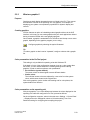
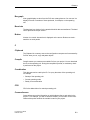
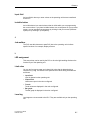
1.1.2
Notation
There are a number of character formats used in this manual to assist reader
orientation.
1-4
Output
Words printed in Courier typeface represent input and
output data as it appears on the screen of the operating
unit.
F1
The names of keys are printed in bold type.
File → Edit
Menu items are printed in italics. Succeeding levels are
separated by arrows. The complete sequence of menu
items leading to the final menu item required is always
shown.
Messages dialog
box
The names of dialog boxes, tabs and buttons are printed
in italics.
ProTool User’s Guide
Release 12/99
Preface
1.2
Other Sources of Assistance
SIMATIC Customer Support Hotline
Available worldwide around the clock:
Nuremberg
Johnson City
Singapore
SIMATIC Basic Hotline
Nuremberg
Johnson City
Singapore
SIMATIC BASIC Hotline SIMATIC BASIC Hotline SIMATIC BASIC Hotline
Local time:
Mon - Fri 7:00 to 17:00
Tel.:
+49 (911) 895-7000
Fax:
+49 (911) 895-7002
E-mail:
simatic.support@
nbgm.siemens.de
Local time:
Mon - Fri 8:00 to 19:00
Tel.:
+1 423 461-2522
Fax:
+1 423 461-2231
E-mail:
simatic.hotline@
sea.siemens.com
Local time:
Mon - Fri 8:30 to 17:30
Tel.:
+65 740-7000
Fax:
+65 740-7001
E-mail:
simatic.hotline@
sae.siemens.com
SIMATIC Premium
Hotline
(chargeable,
available only with
SIMATIC Card)
Times:
Mon - Fri 0:00 to 24:00
Tel.:
+49 (911) 895-7777
Fax:
+49 (911) 895-7001
ProTool User’s Guide
Release 12/99
1-5
Preface
SIMATIC Customer Support Online Services
SIMATIC Customer Support Online Services offer extensive additional information
about SIMATIC products as follows.
•
Up-to-date general information is available
− on the Internet at http://www.ad.siemens.de/simatic
− by fax polling on 08765–93 02 77 95 00
•
Up-to-date product information and downloads for practical use can be obtained
from
− the Internet at http://www.ad.siemens.de/support/html-00/
− the bulletin board system (BBS) in Nuremberg (SIMATIC Customer
Support Mailbox)
on +49 (911) 895–7100.
To call the mailbox, you should use a modem with a transmission rate of
up to V.34 (28.8 kbd) using the following settings: 8, N, 1, ANSI, or you
can connect via ISDN (x.75, 64 kbit).
1-6
ProTool User’s Guide
Release 12/99
Introduction
ProTool User’s Guide
Release 12/99
2
2-1
Introduction
2.1
What is ProTool?
Configuring Windows-based systems
ProTool/Pro consists of the ProTool/Pro CS (Configuration System) configuration
software and the ProTool/Pro RT (Runtime) process visualization software.
•
Configuration software
With ProTool/Pro CS, you create your configuration on a PC in Windows® 95,
Windows® 98 or Windows® NT.
You use the same configuration software to configure all the devices in the
family. Regardless of the device for which you are creating your project,
ProTool always presents you with the same, familiar user interface.
•
Process visualization software for the runtime system
With ProTool/Pro RT, you run your configuration in Windows® 95,
Windows® 98 or Windows® NT. ProTool/Pro RT can run on both a standard PC
and the OP37/Pro.
The ProTool/Pro RT runtime software is software-protected. This means every
runtime software installation on standard PCs requires valid permission for it to
run without restrictions. If the permission is not available, ProTool/Pro RT runs
in Demo mode.
Note
No license is required for the following devices: TP170A, MP270, OP37/Pro, FI25,
FI45, PC670 and PC670T.
2-2
ProTool User’s Guide
Release 12/99
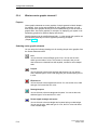
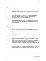
Introduction
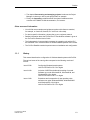
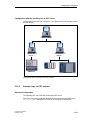
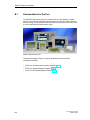
Example of the structure:
ProTool/Pro CS
PC
ProTool/Pro RT
PLC
PC
Example: one PC for configuration and a second PC as the operating unit:
ProTool is easy to use and versatile
The fully graphical user interface of ProTool/Pro CS allows you to create objectoriented, symbol-based projects easily by mouse click. No special programming
knowledge is required. ProTool/Pro features:
•
Convenient process visualization with a large selection of standardized
input/output fields, bar graphs, trend graphics, raster and vector graphics and
attributes with dynamic capability
•
An integrated message system
•
Archiving of process values and messages
•
User functions on the basis of Visual Basic Script®
•
Drivers for connection to the SIMATIC S5, SIMATIC S7, SIMATIC 505 and
many PLCs from other manufacturers.
ProTool User’s Guide
Release 12/99
2-3
Introduction
ProTool and SIMATIC STEP 7
ProTool can be integrated in the SIMATIC STEP 7 configuration software. Thus
allowing you to select STEP 7 symbols and data blocks as tags in ProTool. This
not only saves you time and money but also eliminates the possibility of errors
made when entering the same data several times.
You will find more information on configuring ProTool with SIMATIC STEP 7 at
Configuring with ProTool integrated in STEP 7 (Chapter 3.2).
Offline configuration
With ProTool you create and edit your projects offline. The device need not yet be
available at this time. The configuration computer displays the configured project
data as it will subsequently be displayed on the device.
On completion of configuration you can download the executable project file from
the configuration computer to the device.
2-4
ProTool User’s Guide
Release 12/99
Introduction
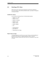
2.2
What is supplied with ProTool
PLC drivers
ProTool is shipped as standard with drivers for the following PLCs:
•
Siemens PLCs
− SIMATIC S5
− SIMATIC S7
− SIMATIC 505
− SIMATIC WinAC (version 2 or higher)
•
OPC network
•
PLCs of other manufacturers:
− Allen-Bradley DF1
− MITSUBISHI FX
− Telemecanique Uni-Telway
Sample projects
ProTool is shipped with ready-made sample projects for different PLCs.
Specially for Windows-based systems, there are examples for SIMATIC S7300/400 for the PC and MP270.
The examples are located in the ProTool directory under ..\SAMPLES. The
directory also contains the associated PLC programs. The sample project and PLC
program are matched to each other.
Libraries
Once ProTool is installed, the following libraries are available to you in the
..\Library directory:
•
PC-Dynamic-Objects.lib
• PC-MP-Pipes-and-more.lib
• PC-MP-Switches.lib
• Symbol-bmp.lib
In ProTool, you open these libraries in the screen editor with Edit → Libraries →
Open.
Microsoft® Visual Basic® Script
You use VBScript to create user-specific functions and scripts.
ProTool User’s Guide
Release 12/99
2-5
Introduction
2.3
Getting started: configuring Windows systems
If you are not all that familiar with the ProTool/Pro visualization software, we would
recommend you read this brief introduction and get started with ProTool/Pro with
the help of the example. The printed version is enclosed with this manual.
Requirements for working with the brief introduction
To do the exercises for ProTool/Pro CS in this brief introduction, you require
•
a PC as a configuration computer
•
the SIMATIC ProTool/Pro 5.2 software package
ProTool/Pro includes the ProTool/Pro CS configuration software and
ProTool/Pro RT runtime software.
•
an operating unit - for example, OP37/Pro.
Other documents on ProTool/Pro CS
You will find the electronic manuals on the ProTool CD under:
Docs\..\UsersManual_Win.pdf
You can find all the information contained in this manual in ProTool’s online Help.
2-6
ProTool User’s Guide
Release 12/99
Installing and configuring ProTool
3
Overview
In this chapter you will learn
•
the requirements the configuration computer must meet and
•
how to install ProTool.
ProTool User’s Guide
Release 12/99
3-1
Installing and configuring ProTool
3.1
Installing ProTool
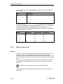
System requirements
The following table shows the recommended system requirements for running the
ProTool configuration software.
Configuration
Recommendation
CPU
Pentium 133 MHz
Main memory
64 MB
Free hard disk space
150 MB for ProTool/Pro CS
20 MB for ProTool/Pro RT
5 MB for every further language
Drive
CD-ROM
Operating system
Microsoft Windows 95 with Service Pack 1
(Build 950a)
Microsoft Windows 95 OSR 2 (Build 950b)
Microsoft Windows 98
Microsoft Windows NT 4.0 with Service
Pack 3
Microsoft Windows 2000
Remark
Service Pack 1 must not be installed on a Windows 95 OSR 2 (Build 950b) or
higher.
Integration in STEP 7
If you have STEP 7 programming software as of V4 on your computer, you can
also install ProTool integrated in STEP 7.
This has the following advantages:
3-2
•
You manage ProTool projects using SIMATIC Manager (i.e. the same
management tool that you use for your STEP 7 projects).
•
You can select STEP 7 symbols and data blocks from the S7 symbol table as
tags. The data type and address are entered automatically.
•
ProTool lists all the PLCs in your STEP 7 project and, once a PLC has been
selected, determines the associated address parameters.
•
In STEP 7 you can configure ALARM_S messages and output them to the
operating unit.
ProTool User’s Guide
Release 12/99
Installing and configuring ProTool
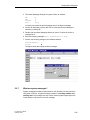
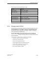
Selecting languages
The installation program prompts you for the options and languages to be installed.
If you wish to install several languages simultaneously, select the User defined
option when you are installing. You can then change the ProTool language later
without having to reinstall ProTool by opening Start Menu→ Simatic → ProTool CS
→ ProTool Setup. During installation you specify the language that you want to be
active after installation.
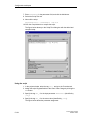
Installing ProTool from a CD-ROM
To install ProTool, proceed as follows:
1. Insert the installation CD in the CD-ROM drive. If the autorun function for your
CD-ROM drive is activated, the browser starts automatically when you insert
the CD.
Alternatively, select the CD-ROM drive in Explorer, and double-click
install.exe to start the installation program.
2. Select the installation language you want at Language.
3. Select Installation and install ProTool/Pro CS first, followed by ProTool/Pro RT.
When installing, follow the instructions on the screen.
Note:
Make sure when you are installing ProTool/Pro RT that you do not use blanks in
the path name if you choose to install ProTool/Pro RT under a different path
name from the one proposed.
4. If you have STEP 7 programming software as of V4 on your computer, you can
also install ProTool integrated in STEP 7.
ProTool checks in Setup whether STEP 7 is installed on your system. If STEP 7
is has been installed, you can choose whether ProTool should be installed in
Integrated or Stand-alone mode.
5. Install the license when prompted to do so. If you do not have a license when
you are installing ProTool/Pro Runtime, you can install it later.
The procedure for this is described in commissioning instructions, software
protection.
6. Reboot your PC so that all registrations can be performed.
Installing ProTool from a hard disk
In order to install ProTool from the hard disk, you first have to copy al the folders
and all their subfolders, including all their files in the main folder, from the CD to
the hard disk:
ProTool User’s Guide
Release 12/99
3-3
Installing and configuring ProTool
Installing ProTool from floppy disk
The installation disks can be ordered separately. However, you can create them
yourself by copying the subfolders DISK 1 to DISK n of the folder called
\PROTOOL from the CD to separate floppy disks. The DISK n folders on the CD
can each be copied to a floppy disk.
Begin the installation with DISK 1.
Uninstalling ProTool
On the Windows start menu at Settings → Control Panel → Software, choose
ProTool and installed options from the and click Add/Remove.
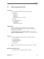
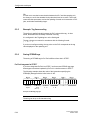
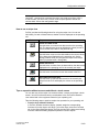
Starting ProTool
After ProTool has been installed, you will find a folder on the Start menu called
Simatic, in which the following symbols are available:
ProTool Pro CS V5.20
ProTool Help
ProTool Pro CS
ProTool ReadMe
ProTool Setup
ProTool Pro RT V5.20
ProTool Pro Disk - Transfer
ProTool Pro RT
ProTool Pro RT ReadMe
ProTool Pro Simulator
3-4
ProTool User’s Guide
Release 12/99
Installing and configuring ProTool
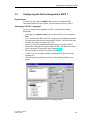
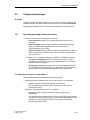
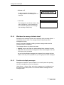
3.2
Configuring with ProTool integrated in STEP 7
Requirements
If the PLC you are using is a SIMATIC S7 and you have installed STEP 7
configuration software on your system, you can integrate ProTool in STEP 7.
Advantages of STEP 7 integration
As you are using the same database as STEP 7, you have the following
advantages:
•
You assign your symbolic name once only and can then use it everywhere.
Note
If you use an instance DB in the STEP 7 program, the corresponding instance
FB must also be defined in the symbol table in STEP 7. If this is not the case,
this DB is not offered for selection in ProTool.
•
When you configure variables and area pointers, you access the STEP 7
symbol table. Changes to the symbol table in STEP 7 are updated in ProTool
(refer to the figure at Properties of tags (Chapter 5.3.2)).
•
When the project is compiled, the data is synchronized.
•
In STEP 7 you can configure ALARM_S messages and output them to the
operating unit.
•
The communication parameters of the PLC are transferred directly to your
project.
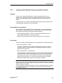
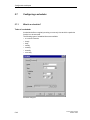
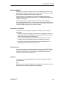
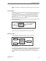
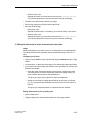
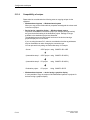
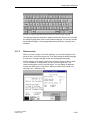
Example Driver Parameters dialog box for integrating STEP 7
ProTool User’s Guide
Release 12/99
3-5
Installing and configuring ProTool
Integrating ProTool projects
Projects created in ProTool on a stand-alone basis cannot be called directly using
SIMATIC Manager. To include projects like this in a STEP 7 project, they have to
be integrated.
To do this, choose the File → Integrate menu command in ProTool. In the STEP 7
configuration, give the ProTool project a different name to the original project.
Note
Conversely, projects created with ProTool on an integrated basis must on no
account be edited with ProTool on a stand-alone basis. If they were, the connection
to the STEP 7 symbol table would be lost.
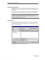
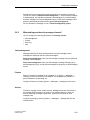
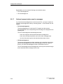
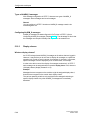
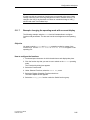
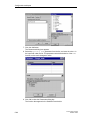
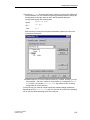
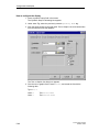
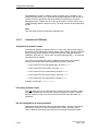
Starting ProTool
Start ProTool directly under Windows. Choose File → New. This opens a dialog
box in which you select a STEP 7 project and create a ProTool project in it. You
then select the operating unit.
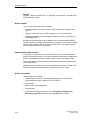
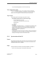
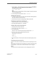
Example of the New dialog box for integrating STEP 7
3-6
ProTool User’s Guide
Release 12/99
Creating projects
4
Overview
In this chapter you are given an overview
•
of the project structure and
•
the procedure for creating a project.
ProTool User’s Guide
Release 12/99
4-1
Creating projects
4.1
Fundamental considerations when creating a project
Objective
To operate and monitor a machine or process. To do this, you map the machine or
process on the operating unit as accurately as is necessary.
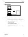
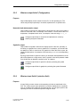
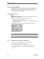
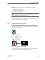
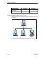
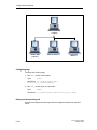
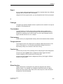
System configuration
Communication takes place between the operating unit and the machine or
process by means of tags via the PLC. The value of a tag is written to a memory
area (address) on the PLC, from where it is read by the operating unit.
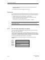
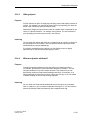
The following diagram provides an overview of the fundamental structure:
Operating unit
Printer
Communication
by means of tags
PLC
Machine,
process
A typical structure
Defining an operating philosophy
Consider which process values or states of the machine you want to display on the
operating unit or work with and which object types you will have to configure for
the purpose.
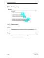
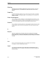
1. Creating a user interface
Screens are the central constituents of the project, with which you visualize the
states of the machine or process and create the prerequisites for operating the
machine or process.
4-2
ProTool User’s Guide
Release 12/99
Creating projects
Screen 2
Start
screen
Screen 1
Screen 3
Screen n
Example of screen creation
You can create a number of screens with display elements and controls, for
switching between screens, for example, for the user interface with which the
operator is subsequently faced on the operating unit.
2. Process data entry and transfer
In order to enter process data or set new values, you configure input/output
fields, for example. This is also possible as a symbolic display.
3. Process state reporting
To enter and log or archive process states and operating modes on the
operating unit, you configure messages.
4. Defining communication areas
A defined address area on the PLC for data interchange with the operating unit
is addressed by means of an area pointer.
The number of area pointers available varies depending on the selected
operating unit (refer to Setting up area pointers (Chapter 4.5)).
ProTool User’s Guide
Release 12/99
4-3
Creating projects
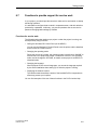
4.2
What does a ProTool project consist of?
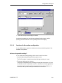
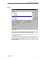
When you open a new or an existing project, the project window opens.
What objects are there in ProTool?
In the project window, the object types you can configure appear on the left, and
the objects themselves appear on the right. The objects that you can configure
depend on the type of the operating unit.
The various objects are linked directly in ProTool with the tool required to edit
them.
What is displayed in the project window?
The project data of a ProTool project is stored in the form of objects. The objects
in a project are arranged in a tree structure.
The Project window displays object types that belong to the project and that you
can configure for the selected operating unit. The project window is comparable
with Windows® Explorer. The object types contain objects with properties that can
be set.
The project window is structured as follows:
• The title bar contains the project name.
• The left half of the screen displays object types that you can configure, and
the right half of the screen displays the objects contained in them.
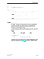
Example of a project window with tags
Note
If you maximize the project window, tabs are displayed for the open windows along
the bottom border to enable you to change easily from one window to another.
4-4
ProTool User’s Guide
Release 12/99
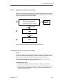
Creating projects
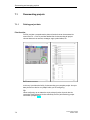
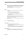
4.3
Steps to be taken when creating a project
To create a project, proceed as follows:
1. Create a new project (File → New or File → Open)
Choose File → New to create a new project. The project assistant guides you
through a number of selection dialogs.
2. Select a PLC
Select a driver for your PLC. Only those drivers with which the operating unit
can be run are displayed.
3. The project assistant allows you to enter information on the project in the
summary. If you click the Create button, the project window opens.
4. Define communication areas (System → Area Pointers).
To enable the operating unit and PLC to communicate with each other, you
have to define communication areas (Setting up area pointers (Chapter 4.5))
that are to be used by them both.
5. Create a project
This is the most involved part of the work. You can approach it in one of two
ways: Either you create all the individual parts first and then link them to form a
meaningful structure (the bottom → up approach), or you begin by designing a
structure and then fill it with the individual elements (the top → down
approach).
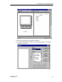
To do this, you basically have to perform the following steps:
− Create the user interface with display and controls.
− Configure tags in order to enable data interchange with the PLC.
− Configure messages in order to obtain information on the state of the
machine or process.
− Split the display on the operating unit.
In addition, you can configure additional objects, such as scripts, depending on the
operating unit.
ProTool User’s Guide
Release 12/99
4-5
Creating projects
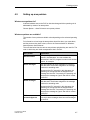
4.4
Selecting a PLC driver
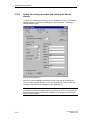
Select the PLC driver with the project assistant in the Select PLC dialog box.
You can also define or later edit the parameters there if you select PLC Properties
in the project window.
Available PLC drivers
You can select the following drivers for Windows-based systems:
•
SIMATIC S5 - AS511
•
SIMATIC S5 - DP
•
SIMATIC S7-300/400
•
SIMATIC S7-200
•
SIMATIC WinAC
•
SIMATIC 500/505
•
OPC
•
Allen-Bradley DF1
•
MITSUBISHI FX
•
Telemecanique Uni-Telway
Repercussions for tags
The address depends on the PLC you are using. The way in which the address of
a tag with a PLC connection is displayed depends on the PLC selected.
Select the available data types and data formats in the Tag dialog box under Type
or Format.
4-6
ProTool User’s Guide
Release 12/99
Creating projects
4.5
Setting up area pointers
What are area pointers for?
A defined address area on the PLC for data interchange with the operating unit is
addressed by means of an area pointer.
Choose System → Area Pointers to set up area pointers.
What area pointers are available?
The number of area pointers available varies depending on the selected operating
unit.
For information on how large the area pointers should be when you create them,
and the structure they have to have, refer to the Communication for Windowsbased Systems User’s Manual.
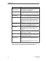
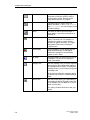
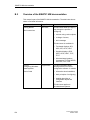
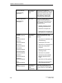
The overview below lists the various area pointers and what they are used for. The
order in which they are listed corresponds to that in ProTool.
Area pointer
Explanation
Screen number
The operating unit stores information on the current
screen in this data area. You can evaluate this
information in the PLC program in order to call another
screen, for example.
Event messages
You can configure an event message for each bit in
this data area. The bits are assigned to the message
numbers in ascending order.
As soon as the PLC sets a bit in this data area, the
operating unit recognizes that the assigned event
message has "arrived". Conversely, the operating unit
interprets the message as "gone" after the bit is reset
in the PLC.
Alarm messages
You can configure an alarm message for each bit in
this data area. The bits are assigned to the message
numbers in ascending order.
As soon as the PLC sets a bit in this data area, the
operating unit recognizes that the assigned alarm
message has "arrived". Conversely, the operating unit
interprets the message as "gone" after the bit is reset
in the PLC.
PLC
acknowledgement
ProTool User’s Guide
Release 12/99
The PLC uses this area to indicate to the operating
unit which alarm messages have been acknowledged
by the PLC.
4-7
Creating projects
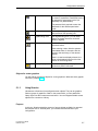
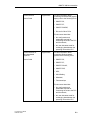
Area pointer
Explanation
OP
acknowledgement
The operating unit uses this area pointer to indicate to
the PLC which alarm messages have been
acknowledged on the operating unit.
LED assignment
The PLC can use this area pointer to drive the lightemitting diodes on the function keys of the operating
unit.
Trend request
The PLC can use this area pointer to determine which
trend is currently being displayed on the operating unit.
Trend transfer area 1
This data area is used to trigger trends. As soon as the
PLC program sets the bit assigned to the trend and the
trend communication bit in the trend transfer area, the
operating unit detects the trigger and, depending on
the configuration, reads out either a value or the entire
buffer.
Trend transfer area 2
This data area is required when you configure trends
with a switch buffer. The data area is structured in the
same way as the trend transfer 1 data area.
Coordination
The PLC can use this data area to query the status of
the operating unit (e.g. startup of the operating unit,
current operating mode and communication
readiness).
Job mailbox
The PLC uses this data area to transfer jobs to the
operating unit in order to trigger specific functions (to
display a screen, for example).
Date/Time
The operating unit writes the date and time in this data
area in accordance with a PLC job. This data can be
evaluated by the PLC program.
Date/Time PLC
The operating unit reads from this data area in the set
date/time data entry cycle to synchronize with the
PLC.
The date and time must be stored in the PLC in the
format S7_DATE_AND_TIME.
Detailed information on the structure of the individual communication areas can be
found in the Communication for Windows-based systems User’s Guide.
4-8
ProTool User’s Guide
Release 12/99
Creating projects
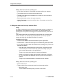
4.6
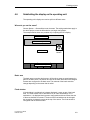
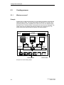
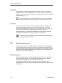
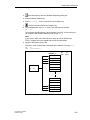
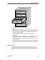
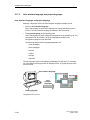
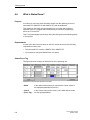
Subdividing the display on the operating unit
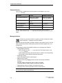
The operating unit’s display area can be split into different areas.
Where do you set the areas?
Choose System → Screen/Keys to set the areas. The settings made here apply to
the whole project, so set the areas before you begin configuration.
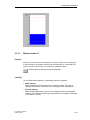
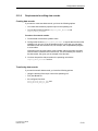
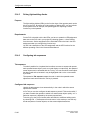
The example below shows one possible way of splitting the OP’s display:
Fixed window
Event message window
Basic area
Message
indicator
Function key assignment
A typical display subdivision
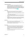
Basic area
The basic area covers the whole screen. All the other areas are superimposed on
parts of the basic area. The position and size of the basic area cannot be changed.
Screens are configured in the basic area. The contents of the basic area thus
change depending on the screen that is called.
Fixed window
A fixed window is a window that is always displayed. It uses up part of the basic
area. The fixed window can be switched on or off under Screen/Keys. If it is
switched on, it is displayed during screen configuration and thus reduces the size
of the area available for screens. The size of the fixed window can be changed,
but its position is always the same at the top of the screen. The fixed window is
configured with the Screens editor.
ProTool User’s Guide
Release 12/99
4-9
Creating projects
Message indicator
The message indicator is a symbol indicating alarm messages that are still
applicable on the operating unit. You can switch the message indicator on or off by
choosing System → Screen/Keys. You cannot change the size, but you can the
position.
Alarm message window
The alarm message window is the window in which alarm messages appear. The
window only opens when there is an alarm message. When you acknowledge the
alarm message, the window closes again.
The display of alarm messages cannot be switched off. Either an alarm message
window or a message line must be configured.
The position and size of the alarm message window cannot be configured.
Event message window
The event message window is the window in which event messages appear. The
window is only displayed when a function is called. You can switch the event
message window on or off by choosing System → Screen/Keys. You can change
the position of the window.
Message line
The message line is the area in which alarm and event messages are displayed.
You can switch the message line on or off by choosing System → Screen/Keys.
You can change the position of the window.
Icons (not PC)
Icons can be placed on the display for soft keys (keys assigned functions locally).
This is only possible for the FX keys arranged around the display.
To find out how to assign keys globally or locally, refer to What are function
keys? (Chapter 5.2.7)
4-10
ProTool User’s Guide
Release 12/99
Creating projects
4.7
Editing projects
4.7.1
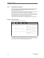
Which projects can you convert?
Windows based system → Windows based system
You can use menu command File → Convert to convert a ProTool project that you
created for a Windows based device into a project for a different Windows based
device. As a necessary precondition, the source and destination devices must
have the same screen resolution.
You can convert the following projects:
Source:
Destination (with the same screen resolution):
OP37/Pro
→
PC, MP270
PC
→
OP37/Pro, MP270
MP270
→
PC, OP37/Pro
TP070
→
TP170
TP170
→
TP070
Device having a graphics display → Windows based system
You can even create a new project for a Windows based system (such as an
OP37/Pro) from an existing project for a device having a graphics display (such as
an OP37). You do this by selecting from the source project window all the screens
and objects that you wish to reuse. Drag and drop the selected objects into the
destination project window. ProTool will tell you if there are any objects and
functions that cannot be converted.
Having completed the copying procedure, you can then adapt the way screen
objects are arranged and displayed in the destination project, as well as the way
function keys are assigned.
Note
Global function key assignments and configured area pointers are not copied.
Configure these again after copying to the destination device.
You can find information about copying objects under the heading Copying objects.
ProTool User’s Guide
Release 12/99
4-11
Creating projects
4.7.2
Example: How to convert an OP37/Pro project
To convert an OP37/Pro project into an MP270 project, proceed as follows:
1. Open the existing OP37/Pro project.
2. Choose the File → Convert menu command.
3. Enter a directory and name for the new project.
4. At Device type select MP270.
5. Click Save. If you confirm the query that appears in response to this, the
project is converted and the MP270 project window opens.
4.7.3
Example: How to convert an OP37/Pro project for the PC
You want to convert an OP37 project for a standard PC and use a different
connection.
If you are using the same PLC, the tag addresses may be discarded even when
changing the connection type.
To prevent this, follow the sequence given below:
Source:
OP37 project
using SIMATIC S5 L2-DP
(Intermediate step 1:
OP37 project
using SIMATIC S5-AS511)
(Intermediate step 2:
PC project
using SIMATIC S5-AS511)
Destination project:
PC project
using SIMATIC S5-DP
Perform the following steps:
1. Open the existing OP37 project.
2. Select the PLC and under Edit → Properties choose the new driver:
SIMATIC S5-AS511
3. Save the project under a new name.
4. Create a new project for the PC and in the Select PLC dialog, choose
SIMATIC S5-AS511 as the driver.
5. Copy all the objects from the OP37 project to the PC project.
6. In the PC project, select the PLC and under Edit → Properties choose the new
driver: SIMATIC S5-DP
7. Save the project with the new driver.
4-12
ProTool User’s Guide
Release 12/99
Creating projects
4.7.4
Copying objects: Between projects and within a project
Principle
You can cut or copy selected parts of your project and paste them via the
clipboard. For example you can copy text and fields from the alarm message
editor to the event message editor, or graphic elements from one screen to
another.
The prerequisite for successful copying between projects is that the system limits
of the destination project must not be exceeded.
Preparations for new projects
Before starting to copy objects from an existing project, you should without fail
carry out the following global settings in the new project. This will ensure that no
loss of data occurs during copying due to different settings.
•
Under the heading System → Screen / Keys make the subdivision of the
screen display the same as in the source project.
•
Make the name and driver of the PLC the same as in the source project.
Procedures
There are two ways of pasting objects from the clipboard to the destination project:
•
Menu command Edit → Paste
The object is pasted from the clipboard to the destination project. If there is
already an object of the same name in the destination project, the object is
pasted under a new name.
•
Menu command Edit → Paste Special
Only objects that are different are pasted. If there is already an identical object
of the same name in the destination project, this is used. If there is an object
that has the same name but is not identical, the object from the clipboard is
pasted under a new name. You can utilize this copying variant to make the
destination project the same as the source project, for instance.
Note
In the case of both Paste and Paste Special, ProTool always checks the underlying
objects (such as the limit value tags of a tag which has been copied) to ensure that
existing objects are reusable.
If there is already an object of the same name in the destination project, the object
to be pasted will be renamed if necessary. It is given the next available name in
the destination project.
ProTool User’s Guide
Release 12/99
4-13
Creating projects
Example:
Tag VAR_4 will be renamed VAR_11 if tags VAR_1 through VAR_10 already exist
in the destination project.
What is copied?
You can copy the following via the clipboard:
•
All objects listed in the project window, such as screens, text or graphic lists,
tags etc.
•
Objects from screens (trends, fields, graphics etc.) in the screen editor.
•
Messages and objects from messages (message text, fields, info text etc.) in
the message editor.
An object is copied complete with its attributes and all cross-referenced objects.
Special situations encountered during copying are reported in the system message
window under Clipboard. This gives you information about any objects that have
not been copied or renamed, for example.
Special situation with screens
If the object to be copied refers to a screen that does not exist in the destination
project, the underlying screen is not copied; instead a blank screen is created as a
dummy if the destination project does not contain a screen that can be reused.
This ensures that you will not copy the complete source project by mistake along
with the start screen.
Afterward, when you paste the screen via the clipboard, the dummy screen in the
destination project will be automatically replaced by the proper screen.
What is not copied?
These objects are not copied:
4-14
•
Objects that are unknown in the destination project (such as functions or
command buttons when copying from TP27 to OP27)
•
Area pointers
•
Global function key assignments
•
Character sets
•
In the case of multilingual projects, only the languages available in the
destination project are copied. No new languages will be created.
ProTool User’s Guide
Release 12/99
Creating projects
4.7.5
Undoing and redoing actions
Purpose
During configuration, it may become necessary to cancel actions which have been
performed, or to reconstruct actions which have been discarded. The two
commands Undo and Redo in the Edit menu are used for this purpose.
•
Undo
The Undo command (key combination Ctrl-Z) cancels the last action
performed. If you keep selecting the command, you can cancel up to 30
successive modifications.
•
Redo
The Redo command (key combination Ctrl-Y) revokes the last action canceled
thus restoring the status before the last Undo command was executed.
Principle
Each active editor (project window, screen editor) has its own undo history. Thus,
for example, if three screens are opened at the same time, three separate Undo
Histories will be created. When a screen is closed, the actions listed in the
accompanying History are deleted. When the project is saved, all the Undo
Histories for the current project are deleted.
The last recorded action is displayed in abbreviated form in the menu. The Tooltips
contain more detailed texts for the Undo and Redo buttons and for the status bar.
Example:
•
•
Menu
Undo:
Redo:
VAR_5 edited
PIC_2 edited
Tooltip/Status bar
Undo:
Redo:
property edited of tag VAR_5
contents edited of screen PIC_2
Ctrl-Z
Ctrl-Y
Until the accompanying Undo History is deleted, deleted objects will continue to be
listed in the cross-reference (Chapter 4.8.1) as used objects. The status of these
objects is given in brackets after each object, e. g. PIC_5 (deleted).
ProTool User’s Guide
Release 12/99
4-15
Creating projects
General Information
The commands Undo and Redo only work with actions taken since the last time
the project was saved. If, for example, you move a screen object and then save
your project, you cannot later cancel this action.
These are some of the rules that apply to Undo/Redo:
•
Settings in dialog boxes (properties of a field) can only be canceled in their
entirety. It is not possible to open the dialog box and discard individual entries.
•
With multilevel dialog boxes, only changes to the primary object are recorded.
Modifications to underlying objects, or creations or deletions cannot be
reversed.
Example (project window):
Editing tags → Editing limit tags.
Only the tag changes can be reversed here.
•
4.7.6
Undo/Redo is ProTool-specific. With a project integrated in STEP 7, the Undo
buffer cannot be accessed by a higher-level Step 7 Undo Manager.
Undoing the last action
To undo your last action in ProTool, choose one of the three following options:
•
Choose the Edit → Undo menu command.
The last action that can be undone (canceled) is shown in abbreviated form
after the menu command. A longer description is given in the status bar.
•
Click the Undo button in the toolbar.
This opens a Tooltip which shows you the last action that can be undone
(canceled). You are given the same information in the status bar.
•
Press the CTRL and Z keys simultaneously.
In contrast to the first two options, you are not given any feedback about which
action has been canceled.
If you keep executing the Undo command, you can successively cancel all the
recorded modifications.
4-16
ProTool User’s Guide
Release 12/99
Creating projects
4.7.7
Redoing the last action
To redo your last canceled action in ProTool, choose one of the three following
options:
•
Choose the Edit → Redo menu command
The last canceled action is shown in abbreviated form after the menu
command. A longer description is given in the status bar.
•
Click the Redo button in the toolbar.
This opens a Tooltip which shows you the last canceled action. You are given
the same information in the status bar.
•
Press the CTRL and Y keys simultaneously.
In contrast to the first two options, you are not given any feedback about which
action has been restored.
If you keep executing the Redo command, you can successively restore all the
recorded cancellations.
ProTool User’s Guide
Release 12/99
4-17
Creating projects
4.8
Retrieving project information
The following tools are available to you for displaying or storing information on a
project.
4.8.1
•
Cross-references
•
Project information
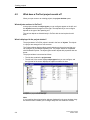
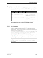
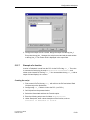
What is displayed in the "Cross-Reference" window?
Usage
When you have to add to or modify a project and need to check where and how a
particular object is used in your project, you open the Cross-Reference window.
You select an object in this window, and all the references to this object in the
project are then displayed to you.
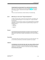
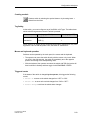
Example from a project
You open the Cross-Reference window by choosing the View → Cross-Reference
menu command. The active object is displayed with a red border around it.
4-18
ProTool User’s Guide
Release 12/99
Creating projects
The selected object is at the uppermost level, and all the objects in which the
selected object is used appear under it. The cross-reference list also contains
object in the current undo history (Undo actions (Chapter 4.7.5)). The status of
these objects is shown in brackets behind the object concerned - for example,
PIC_5 (deleted).
Tip
You can use the Cross-Reference window efficiently for troubleshooting.
4.8.2
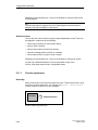
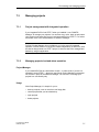
What can you view under "Project Information"?
To obtain information about a project when projects change or are adapted, open
the Project Information dialog box. To do so, choose File → Project Information
from the menu.
The Project Information dialog box displays general project data and the memory
required by the project. Project information is spread according to subjects over
three tab controls:
• General
• Description
• Statistics
General
The General tab control shows information on the device type, project name, path
name of the stored project file and creator of the project. You fill in the Creator
field and all the other fields are updated automatically by ProTool upon saving the
project.
Description
The Description tab control contains an input field for the project description. Here
you can enter any information you like that are important for your project.
Statistics
The Statistics tab control shows when the project was created, modified, generated
and downloaded, the ProTool version last used to edit the project and the memory
required by the project after it has been downloaded to the flash memory on the
operating unit. The memory requirement is determined and displayed following
the first download operation.
ProTool User’s Guide
Release 12/99
4-19
Creating projects
4-20
ProTool User’s Guide
Release 12/99
Configuration techniques
5
Overview
In this chapter you will learn how to
•
create screens
•
configure controls and display elements
•
use tags
•
configure messages
After that we will show you, for example, how you
•
use functions
•
create archives
•
create recipes
•
assign operator authorization
•
create multi-lingual projects
ProTool User’s Guide
Release 12/99
5-1
Configuration techniques
5.1
Creating screens
5.1.1
What are screens?
Example
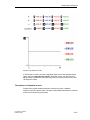
Screens are an image of the process. You can display processes on screens and
specify process values. The figure below shows an example of a mixing unit for
producing different juices. Ingredients are filled into a mixer from different tanks
and then mixed. The liquid levels in the tanks and in the mixer are displayed. The
intake valves can be opened and closed by means of the operating unit. The
motor for the mixer can be turned on and off in a similar manner.
Quantity in tank (in l)
Tank 1:
Tank 2:
Tank 3:
Bottling machine:
Mixing unit
Tank 2
Tank 1
Tank 3
Valve 4
Quantity in
mixer (l)
to bottling machine
off
on
Soft key/button
Help
ESC
Fixed window
Example of a Screen: Mixing Station
5-2
ProTool User’s Guide
Release 12/99
Configuration techniques
Components of a screen
A screen can consist of static and dynamic components. Static components for example, text and graphics - are not updated by the PLC. Dynamic
components are linked to the PLC and visualize current values from the PLC
memory. Visualization may take place in the form of alphanumeric displays, trends
and bar graphs. Dynamic components are also inputs made by the operator on the
operating unit and written to the PLC memory. The link to the PLC is established
by means of tags (refer to Using tags (Chapter 5.3.1)).
Screen editor
Screens are created with a separate editor in ProTool. The operating unit is
displayed when you call the screen editor. Open the screen editor by:
•
double-clicking on Screens in the left half of the project window to create a new
screen
•
double-clicking in the right half of the project window on an existing configured
screen to open the screen for editing.
You can zoom this display in and out by choosing View → Zoom from the menu. If,
for example, you wish to edit details you can do it much more simply by zooming
in on them.
Screens are stored under a symbolic name. You enter a name by choosing Edit →
Properties from the menu. This name has to be specified when you edit, reference
or delete the screen. In addition, screens are numbered automatically.
Start screen
Declare one screen in every project as a start screen. The start screen is the
screen that is displayed after the operating unit has started up.
To identify a screen as the start screen, select the screen and assign it as the start
screen by choosing Edit → Properties from the menu.
Fixed window
The fixed window is the window that is always flush with the top border of the
operating unit screen. By choosing System → Screen/Keys from the menu, you
can open and close the fixed window and adjust its height by dragging with the
mouse. Since the contents of the fixed window do not depend on the current
screen, you can output important process tags or the date and time to it,
for example.
You configure the contents of the fixed window in the screen editor. To access the
fixed window, click it with the mouse.
ProTool User’s Guide
Release 12/99
5-3
Configuration techniques
Soft keys/buttons
Soft keys are function keys configured for specific screens (refer to What are
function keys? (Chapter 5.2.7)). Buttons are virtual keys on the operating unit
screen (refer to What are buttons? (Chapter 5.2.10)). You can configure both soft
keys and buttons for specific screens. When configuring, you assign functions to
these controls. You can illustrate the task of a control by means of a graphic or
text.
You can use soft keys and buttons to open another screen, turn a motor on and off
or display the message buffer, for example.
Selecting screens
Every configured screen has to be integrated into the control process so that it can
be opened at runtime on the operating unit. The Select Screen function is
available for this purpose. You an assign this function to an input field, a function
key or a button, for example. You specify the name of the screen as the
parameter. This means that a screen can be displayed by means of an input field
or a function key or button.
With input fields, soft keys and buttons, the function can be used only locally on
that screen. Should you wish the function to be available globally, you have to
configure the function on a globally assigned function key or on a button
positioned in the fixed window.
5.1.2
Screen objects in ProTool
Screens consist of individual objects. There are different types of object, which you
can use at will when configuring a screen. "At will" means that you determine the
number and type of the objects, as well as their position and size.
The following table gives you short descriptions for the most important screen
objects. Not all the screen objects listed here are necessarily available for every
destination device.
Screen
object
5-4
Name
Description
Graphic
With the graphic field, you can use graphics
from other graphics programs in your
project.
Text
You can configure static texts with the text
box. Various formats are available. You can
display text in different fonts, enter several
lines of text and align it vertically or
horizontally.
ProTool User’s Guide
Release 12/99
Configuration techniques
Output field
With the output field you can display process
values directly. Different display formats - for
example, decimal and binary - are possible.
There are a large number of formatting
options, such as 3D effects, colors, flashing
etc.
Input field
With the input field, you can enter values of
different formats directly on the operating
unit. You can, for example, set limit values
for the input, or protect the input field with a
password.
Date/Time
With Date/Time you can display and set the
system time numerically.
Symbolic output field
Instead of a numerical value, a symbolic
output field displays a text or a graphic to
make the current status more
comprehensible to the operator.
The assignment between the values of the
tags and the text or graphics is configured in
a text or graphic list (text list or graphic list).
Example:
Instead of the values 0 and 1, you can
output the texts Motor OFF and Motor ON
on the operating unit.
List box
In list boxes, you select a piece of text for
entry from the text list to make the setting
more comprehensible for the operator.
Example:
Instead of the values 0 and 1, you can
output the texts Motor OFF and Motor ON.
Graphic list
The graphics list displays a graphic from a
list, to make the current status more
comprehensible to the operator.
Example:
Instead of the values 0 and 1, you can
display a graphic for a closed valve and a
graphic for an open valve.
ProTool User’s Guide
Release 12/99
5-5
Configuration techniques
Button
Buttons are objects that trigger configurable
functions by clicking a mouse or using a
touch-sensitive screen. Buttons can be
freely labeled with text or a graphic.
Status button
The status button is used to input and
display two states: ON and OFF or pressed
and not pressed. You can configure it with
or without latching.
Switch
The switch is used to input and output a
binary status. It can only be switched on or
switched off.
Invisible button
With invisible buttons, their contours are not
visible. The button can, for example, be
placed over a graphic, to allow indirect
operation of graphic elements. You trigger
configurable functions by touching an
invisible button.
Trend display
In a trend display, you can display several
trends simultaneously. A trend display
contains the settings for the coordinate
system (X and Y axes).
Bar graph
Bar graphs display a value from the PLC as
a rectangle. You can use it to display fill
levels, for example.
Message view
With the message view, you define separate
filter criteria for the volatile buffer display or
the message archive display. To display the
message archive, you must have configured
a message view.
All the features offered for message display
by default only access the volatile message
buffer.
Status/Force
With this screen object, you implement the
functionality of Monitor Tag and Control Tag
on the SIMATIC S5 and SIMATIC S7 PLCs
(apart from S7-200).
You mainly use these functions to test your
project.
5-6
ProTool User’s Guide
Release 12/99
Configuration techniques
Password list
In ProTool you can protect entry operations
by means of a password. Passwords have to
be assigned for permission levels 0 (no
password) to 9 (administrator).
The password list is required to enter the
passwords for the different permission
levels.
Recipe view
With recipe view, you can display and edit
data records on the operating unit.
Digital/analog clock
With digital/analog clock, you can either
display the system time as a clock with
hands, or digitally.
Slider control
Use the slider control to enter and display
numerical values.
When entering values, slide the operatorcontrollable slider, for example, with the
mouse or the arrow keys, to the desired
position.
When it is used as a display element, the
value to be displayed is derived from the
position of the moving slider.
Analog display
Use the analog display to display numerical
values as a pointer instrument.
Objects for vector graphics
You will find an overview of objects for vector graphics in What are vector graphic
elements? (Chapter 5.2.4)
5.1.3
Using libraries
Libraries are collections of preconfigured screen objects. They can be graphics,
fields or groups of graphics or fields. In the screen editor, you can paste each
library object into the current screen and edit it. You can integrate suitable screen
objects from a screen to a library.
Purpose
In this way, libraries extend the amount of screen objects available: by repeated
and frequent use of "finished parts", you increase the effectiveness of your
configuration.
ProTool User’s Guide
Release 12/99
5-7
Configuration techniques
Standard libraries
Once ProTool is installed, the following libraries are available to you in the
\Library directory:
File name
Content
suitable for devices
PC-Dynamic-Objects.lib
Analog clock, analog
pointers and sliders
OP37Pro, FI25/45,
PC670, PC, MP270
PC-MP-Pipes-and-more.lib Pipes, pumps, tanks and
valves
PC, MP270
PC-MP-Switches.lib
Switches
PC, MP270
Symbol-bmp.lib
Technical standard symbols all
Touch-Switches.lib
Buttons
TP27, TP37
You can add further libraries to this directory yourself and then use them in
ProTool. Files must be of the *.lib type and have the same format as a ProTool
library.
Managing libraries
As soon as you open a screen in a project, you have access to the menu
items under Edit → Libraries or to the icon button.
Once you open the first library, the library window on the screen is active. The first
library opened and all those subsequently opened are shown together here, as a
tree structure.
The following functions are available to assist you in managing your libraries:
• Adding additional libraries:
− Add a file which is of the *.lib type and in ProTool library format, to the
\Library directory.
•
•
•
•
− Use the New menu item in the shortcut menu to create a new, empty library.
Save a library under a different name and then edit it.
Renaming a library:
Use the Windows functions in the Explorer.
Restructuring a library:
Edit the overview by dragging with the mouse or by using the Windows
functions.
Use New Folder in the shortcut menu to add a new folder.
To rename folders or library objects, click twice or press F2.
Deleting library objects or folders: Use the shortcut menu.
Deleting a library: Use the Windows functions in the Explorer.
Note
You cannot edit a write-protected library.
5-8
ProTool User’s Guide
Release 12/99
Configuration techniques
Editing library objects
You cannot edit library objects directly, you can only edit them in a project.
Tip
If you want to make changes to a library object: in a project paste the object in
question to a screen, edit it there and move it back to the relevant library. Then
delete the original object and give the one you have just added the same name as
the old one.
5.1.4
Defining colors for screen objects
Color category
You can assign one or more colors to each screen object created in ProTool.
Depending on the screen object, you can configure different colors for the
following color attributes, for example:
•
Background
•
Foreground
•
Exceeding the limit values
Colors
You can allocate a color to each color attribute. Several colors are available to you
for this assignment:
•
Default colors
16 default colors are permanently defined and cannot be changed.
•
Project colors
You can select 8 project colors from a range of colors, at will. These colors are
globally available throughout the project.
To add additional project colors to your colors, select Tools → Colors from the
menu or in the Colors toolbar, double-click on one of the eight project color
fields in Colors.
•
Different colors
For each color attribute, you can also select a personal color from a range of
colors. This color applies to the current color attribute only. It is not globally
available throughout the project.
To assign a personal color, on the Color tab, click the Different Color button.
ProTool User’s Guide
Release 12/99
5-9
Configuration techniques
5.1.5
Setting fonts
Purpose
In all screen objects which contain static or dynamic texts, you can assign
parameters to the appearance of the texts, to mark the significance of individual
texts within a screen. For example, you can select the font, the font style and the
font size and set additional effects, such as strikethrough and underscore.
Settings
Make all the settings in the Properties of the relevant screen object on the Font
tab. For screen objects with a number of texts which can be assigned parameters
(for example, message view, status/control, recipe view), you can, for example,
set different font attributes for titles and default text. Which fonts are available will
depend on the destination device set. Which font properties are available will
depend on the font selected.
Note
Text markings, such as font style (bold, italic, etc.), and effects (strikethrough,
underscore) always refer completely to the selected screen object property. This
means, for example, that you can display all the titles within a screen object as
bold, but not the individual letters or words in a title.
5.1.6
Displaying and setting date/time
The date and time details can be displayed and changed on the operating unit.
Note
The actual date and time format depends on which setting you have selected in
your Windows system.
The following facilities are available for this:
•
You can use a date/time display for screens and reports.
This allows you to set the date and time on the operating unit.
• The digital/analog clock is purely a display element.
This allows you to choose between digital and analog display.
• You can use PLC jobs 14 and 15 to set the date and time, and jobs 40 and 41
to download the details to the PLC.
You will find a list of all the PLC jobs in the ProTool online help system.
• You configure an input/output field with the aid of a tag in a time or date format.
You can set the time on the operating unit by using an input field.
5-10
ProTool User’s Guide
Release 12/99
Configuration techniques
5.2
Configuring display elements and controls
5.2.1
Overview of display elements and controls
Purpose
You use display elements to monitor the machine or the system on the operating
unit. You can display current information, such as actual values from the PLC,
process and operating modes and malfunctions, on the operating unit as a
numerical value, in plain language or as a graphic.
You use controls on the operating unit to intervene directly in the process. They
are used, for example, to specify setpoints, trigger functions, open screens (What
are screens? (Chapter 5.1.1)) and acknowledge messages. You can assign a
password level to controls in order to prevent manipulation by unauthorized
persons.
Overview
Two types of display element are available in ProTool:
•
Static display elements
Static display elements are pieces of text and graphics that are not linked to the
PLC. They do not react to user inputs and cannot be modified at runtime on the
operating unit. Use static display elements, for example, for system screens or
for textual or graphic explanations for controls and dynamic display elements.
Static display elements are
− Static text ( What is static text? (Chapter 5.2.2))
− Graphics (What are graphics? (Chapter 5.2.3))
− Vector graphic elements (What are vector graphic elements?
(Chapter 5.2.4))
•
Dynamic display elements
Dynamic display elements can be linked to the PLC by means of tags. They
visualize current values from the PLC in alphanumeric or graphic form.
Dynamic display elements can change their display spontaneously at runtime
on the operating unit without the operator intervening.
Use dynamic display elements for all tasks associated with monitoring the
process, a machine or the system.
Dynamic display elements are
− Output fields ( What are output fields? (Chapter 5.2.5))
− Bar graphs (What are bar graphs? (Chapter 5.2.9))
ProTool User’s Guide
Release 12/99
5-11
Configuration techniques
− Trend graphics (What are trend graphics? (Chapter 5.2.8))
− Date/time display (What is a date/time display? (Chapter 5.2.15))
− Digital/analog clock ( What is a digital/analog clock? (Chapter 5.2.16))
− Analog display (What is an analog display? (Chapter 5.2.14))
The following controls are available in ProTool:
•
Input fields (Chapter 5.2.6)
•
Function keys (Chapter 5.2.7)
•
Buttons (Chapter 5.2.10)
•
Status button (Chapter 5.2.11)
•
Switch (Chapter 5.2.12)
•
Slider controls (Chapter 5.2.13)
By means of dynamic attributes (What are dynamic attributes? (Chapter 5.14.4))
you can indicate, for example, by means of a change of color or by flashing that
an operator input is expected at the control in a certain situation. Furthermore,
event-driven display and hiding of controls can be performed on the operating unit
(Hiding an object (Chapter 5.14.3)).
Detailed descriptions of the different steps to configuration will be found in the
ProTool online Help.
5.2.2
What is static text?
Static text is text that is not linked to the PLC. It cannot be modified at runtime on
the operating unit. Use static text, for example, to label controls and output fields.
The relative importance of different text strings on a screen can be illustrated by
means of different fonts and properties (size, color, flashing etc.).
Remark for MP270
If you configure a tab in static text on the MP270, this will be replaced by another
character.
You can configure static text separately for any language available on the
operating unit.
Configure static text by selecting the symbol illustrated.
5-12
ProTool User’s Guide
Release 12/99
Configuration techniques
5.2.3
What are graphics?
Purpose
Graphics are static display elements that are not linked to the PLC. They cannot
be modified at runtime on the operating unit. Use graphics, for example, for
displaying your system or as explanatory symbolism for dynamic display and
controls
Creating graphics
ProTool features an option of embedding external graphic editors via the OLE
interface. In this way you can create graphics with your usual applications without
having to become familiar with a new graphics program.
Once created, a graphic is embedded in ProTool either as a bitmap or as a vector
graphic, depending on the graphics program you are using.
Configure graphics by selecting the symbol illustrated.
Tip
To make a graphic so that it can be "operated", configure a button with a graphic
list.
Color presentation in the ProTool project
This setting is only available for operating units with Windows CE.
If the depth of color of the configuration computer is set to a value greater than
256 colors, you can choose between the following settings when inserting
graphics, in order to achieve optimum color presentation:
• Error diffusion (system default):
The screen colors are intermingled to create different shades.
• Similar colors:
The individual screen colors are replaced by a new color from the system
colors, which comes closest to the original color.
With vector graphics, use the similar colors setting and for color photos, the
system default error diffusion.
Color presentation on the operating unit
With pixel graphics, if you notice differences between the colors displayed on the
operating unit and those configured in ProTool, proceed as follows:
On the configuration computer, select in the start menu Settings → Control Panel
→ Display and on the Settings tab, select at Colors the setting True Color.
Retain this setting for configuring and compiling the project.
ProTool User’s Guide
Release 12/99
5-13
Configuration techniques
5.2.4
What are vector graphic elements?
Purpose
Vector graphic elements are vector graphics of simple geometrical basic shapes for example, lines, circles and rectangles. By using graphic elements, you can
draw simple vector graphics directly in ProTool without having to use an external
graphic editor. Use vector graphics, for example, for displaying your system or as
explanatory graphics for dynamic display and controls.
Graphic elements can be modified dynamically - in other words, their position can
be modified dynamically at runtime (Dynamic positioning of objects
(Chapter 5.14.7)).
Selecting vector graphic elements
You can select the following drawing tools for creating simple vector graphics from
the Screen Elements toolbar:
Line
You use this tool to draw different types of line. You can set the color,
width, type and ends of a line. This means, for example, that you can
draw continuous or dashed lines with squared, rounded or arrow-shaped
ends.
Polyline
You use this tool to draw open polylines and polygons. You can set the
color, width and type of a line. With polygons, you can also specify the fillin color.
Ellipse/circle
You use this tool to draw ellipses and circles. You can set the color, width
and type of a line and the fill-in color.
Rectangle/square
You use this tool to draw rectangles and squares. You can set the color,
width and type of a line and the fill-in color.
Round-edged rectangle and square
You use this tool to draw rectangles and squares having rounded edges.
You can set the color, width and type of a line, the fill-in color and radius
of the rounded edges.
5-14
ProTool User’s Guide
Release 12/99
Configuration techniques
5.2.5
What are output fields? (Text/graphics)
Purpose
Output fields display current values from the PLC on the operating unit. The
values may be output optionally in numerical, alphanumeric or symbolic form.
Numerical and alphanumeric output
Output fields for numerical or alphanumeric values show the value as a number or
as text. A numerical value, for example, is the number 80 as the actual value of a
temperature. An alphanumeric value, for example, is the text string Valve_12.
Configure output fields for numerical and alphanumeric values by
selecting the symbol illustrated.
Symbolic output
Output fields for symbolic values do not display the true value but, optionally, a
text string or a graphic from a text or graphic list. For example, you can store the
two states of a valve in a text list or in a graphic list. When the valve is open, the
output field then points, for example, to the text string OPEN or to a corresponding
graphic.
By using output fields for symbolic values, you eliminate misinterpretations on the
part of the operator to a large extent, since a symbolic value often presents a state
more lucidly than an abstract numerical value, for instance.
Configure output fields for symbolic values by selecting the symbol
illustrated.
Configure output fields for graphics by selecting the symbol illustrated.
5.2.6
What are input fields? (selection field)
Purpose
In input fields you enter values on the operating unit that are transferred to the
PLC. The values may be input optionally in numerical, alphanumeric or symbolic
form. If you define limit values for the input field tag, you can reject inputs on the
operating unit that are outside the specified range of values.
ProTool User’s Guide
Release 12/99
5-15
Configuration techniques
Input fields
In input fields for numerical and alphanumeric values you enter the value one
character at a time on the operating unit. A numerical value, for example, is the
number 80 as the setpoint for a temperature. An alphanumeric value, for example,
is the text string Valve_12.
Create input fields for numerical and alphanumeric values by selecting
the symbol illustrated or by choosing Insert → Input Field from the menu.
List boxes
In list boxes you do not enter the value one character at a time but select this
value on the operating unit from a text list. During configuration you assign
symbolic text on the text list to every value of a tag. In this way, for example, you
can turn a motor on and off by means of the two entries ON and OFF.
By using list boxes, you prevent misinterpretations to a large extent, since the
operating unit accepts only the configured values on the text list.
Create list boxes by selecting the symbol illustrated or by choosing Insert
→ Output Field from the menu.
5.2.7
What are function keys?
A function key is a key for configuring a function assignment. You can assign one
or more functions to any function key in ProTool. The functions are triggered as
soon as the key is pressed. The function key assignment may be locally or globally
significant. You can assign a password level to function keys in order to prevent
manipulation by unauthorized persons.
Global assignment
Globally assigned function keys always trigger the same function, irrespective of
the current control situation. You can the open a specific screen, for example,
display queued messages or print the contents of the screen.
By using globally assigned function keys, you cut your configuration effort
considerably since you do not have to assign individual functions to global keys on
every screen.
5-16
ProTool User’s Guide
Release 12/99
Configuration techniques
Assign function keys globally by choosing System → Screen/Keys from
the menu. To do so, click in the Screen/Keys dialog box on the function
key required.
OP37/Pro: Keys K1 through KX or F1 through FX.
You can specify the functions you have assigned to specific keys on the
operating unit by means of labeling strips, if you wish.
Standard PC: Keys F1 through FX.
Note
By choosing System → Screen/Keys you can specify global settings for keys that
apply to all screens. The icons appear in each configured screen provided the
settings are not subsequently overwritten by an individual screen. In that case, the
changes apply only to that particular screen.
Local assignment
Locally assigned function keys trigger different actions on the operating unit
depending on the screen. A function key whose assignment may vary from screen
to screen is referred to as a soft key.
Assign soft keys locally in the screen editor. To do this, click one of
function keys F1 to FX on the screen.
For the OP37/Pro you can assign an icon that illustrates the soft key
function by means of text or a graphic to any soft key.
You can also assign soft keys globally. A global assignment is active on all screens
to which you do not assign a screen-specific function. Use globally assigned soft
keys, for example, to change from any screen to the same system screen.
Note
Do not assign functions that have to be permanently available on the operating
unit to soft keys.
ProTool User’s Guide
Release 12/99
5-17
Configuration techniques
5.2.8
What are trend displays?
Purpose
A trend graphic is a dynamic display element. Trend graphics make possible a
particularly lucid form of continuous display of process data on the operating unit.
You can display several different trends on a trend graphic simultaneously on your
operating unit.
Configure trend graphics by selecting the symbol illustrated.
5.2.9
What are bar graphs?
Purpose
A bar graph is a dynamic display element. Bar graphs display a value from the
PLC as a rectangular area. This means that you can tell at a glance on the
operating unit how far the current value is from the limits or whether a specified
setpoint has been reached. Bar graphs can be used to display fill levels or
quantities, for example.
Configure bar graphs by selecting the symbol illustrated.
Settings
Bar graphs are linked to the PLC by means of a tag. Apart from this tag, which
contains the value that is required to be displayed, you can define other tags in
order, for example, to visualize when a limit value has been reached or to display
or hide the bar field.
You can freely define the direction, scaling, bar and background color and also
labeling of the Y axis. In addition, you can show limit value lines to indicate limit
values.
The following figure shows a bar that is updated vertically and has limit value lines
drawn on it.
5-18
ProTool User’s Guide
Release 12/99
Configuration techniques
5.2.10
What are buttons?
Purpose
A button is a virtual key on the operating unit screen to which you can assign one
or more functions. You operate a button with a pointing device - for example, the
mouse. You can customize the user interface by means of buttons.
Create buttons by selecting the symbol illustrated.
Labeling
You can label buttons statically or dynamically with text or graphics.
•
Static labeling:
When configuring the button enter a text or select a graphic. This type of
labeling is static, which means that it is not changed on the operating unit.
•
Dynamic labeling:
When configuring the button, select a text or graphics list and an associated
index tag. The value of the index tag determines which list element is displayed
on the button at runtime.
ProTool User’s Guide
Release 12/99
5-19
Configuration techniques
Operation
Pressing, clicking and releasing a button triggers the functions that you set for
these events.
If you press a button by mistake and do not want to trigger the function, keep the
button pressed and move the mouse pointer, for example, or your finger (touch
panel) away from the button. This process is not interpreted as a release event.
Invisible buttons
Invisible buttons are transparent buttons that are not displayed upon the operating
unit. If you place invisible buttons on graphics, you can operate parts of the
graphic - for example, a motor or a valve - by clicking the mouse.
Create invisible buttons by selecting the symbol illustrated.
5.2.11
What is a status button?
Purpose
A status button is a display and input element with two states: ON and OFF or
pressed and not pressed. The operator presses the status button by touching the
touch-sensitive screen or clicking with the mouse.
Consequently you can use the status button to indicate the status of a unit to the
operator, for example, of a motor, which he cannot see from the operating unit. At
the same time, the operator can use the status button to change the status of the
relevant unit himself.
You can configure the status button with or without latching. A non-latching status
button is only "on" for as long as it is pressed.
Display
You have the option to assign text or graphics for both display modes, which then
appear on the status button. The following figures show status buttons in different
modes and configuration variants.
5-20
ProTool User’s Guide
Release 12/99
Configuration techniques
Status button with text or graphics
Creating a status button
Create a status button by selecting the symbol shown or by choosing
Insert → Status Button from the menu.
Tag linking
The status button must be linked with a tag of the BOOL or INT type. With a tag of
the INT type, you must also configure the integer value n (≠ 0), which corresponds
to the "ON" status. The table shows which value the tag assumes when the status
button is pressed:
Status
Value (tag type BOOL)
Value (tag type INT)
ON / pressed
TRUE (1)
configured value n
OFF / not pressed
FALSE (0)
0
When linked to an integer tag, the status button shows the status "ON" only if the
tag has the configured value n. With any other value, the status "OFF" is
displayed.
Operation
The status button is primarily intended for use on a touch panel, but it can be
operated with the mouse or the keyboard.
•
Click the mouse on the status button to operate it.
•
On the keyboard, select the status button with TAB or SHIFT + TAB and
operate it with SPACEBAR or Input/Return.
Latching / non-latching
The status button can be configured as latching or non-latching.
•
If the status button is configured as latching, it changes to the opposite position
each time it is operated.
ProTool User’s Guide
Release 12/99
5-21
Configuration techniques
•
If the status button is configured as non-latching, it retains the "ON" position
only while the operator is pressing it (or the mouse button). If the configured tag
assumes the value n by any other means (for example, from the PLC), it
naturally still retains the "ON" position.
Triggered events
If the status of the status button is changed by the operator, this triggers the
following events, to which you can configure one or more functions:
•
Switch on: as soon as the button changes to operated status ("ON").
•
Switch off: as soon as the button changes to non-operated status ("OFF").
•
Status change: each time the status changes.
If the switch status changes because the tag changes, none of the events
described are triggered.
5.2.12
What is a switch?
Purpose
A switch is used to input and output a binary status: it can only be on or off. To do
this, it is linked to a tag of the BOOL or INT type. The status "switched off"
corresponds to the value 0 (or FALSE) of the tag linked to the switch. All tag
values which are not the same as zero, are interpreted as "switched on".
Display
You can configure the switch in both the horizontal and vertical directions; the
"ON" position of the switch toggle is freely selectable. You can label the switch and
also visually highlight the current switch status with a background color.
Switch position marked by a background color
5-22
ProTool User’s Guide
Release 12/99
Configuration techniques
Creating a switch
Create a switch by selecting the symbol shown or by choosing Insert →
Switch from the menu.
Tag linking
At the switch, you must configure a tag of the BOOL or INT type. The table shows
which value the tag assumes when the switch is pressed:
Status
Value (tag type BOOL)
Value (tag type INT)
switched off
FALSE (0)
0
switched on
TRUE (1)
1
When linked to an integer tag, the switch shows the status "switched off" only if the
tag has the value 0. With any other value, the switch is "switched on".
Mouse and keyboard operation
Switches can be operated by the touch panel, the mouse and the keyboard.
•
The operator can move the switch directly with the mouse or by touch. When
you click in the slide opening, the switch is immediately set to the opposite
position and the tag to the corresponding value.
•
With the keyboard, the operator can select the switch with TAB (the border will
then be shown in dashes) and then toggle it with SPACEBAR / ENTER.
Triggered events
If the status of the switch is changed by the operator, this triggers the following
events:
•
Switch on: as soon as the switch changes from "OFF" to "ON".
•
Switch off: as soon as the switch changes from "ON" to "OFF".
•
Status change: each time the switch status changes.
ProTool User’s Guide
Release 12/99
5-23
Configuration techniques
5.2.13
What is a slider control?
Purpose
Use a slider control to enter and display numerical values in analog form. To enter
values, move the operator-controllable slider, for example, with the mouse or the
arrow keys, to the desired position. When it is used as a display element, the value
to be displayed is derived from the position of the moving slider.
Create a slider control by selecting the symbol illustrated.
Settings
The slider control is linked to a tag. When you move the operator-controllable
slider, the corresponding value is written to the tag. Conversely, when the tag
value is changed, so is the position of the moving slider, unless this is just being
changed by the operator.
Apart from the tag containing the value to be displayed/entered, you can define
other tags in order, for example, to modify dynamically the values for the upper
and lower stop at runtime.
You can also configure, for example, the following attributes, in order to adapt the
slider control to meet your individual requirements:
•
Labeling
•
Axis labeling
•
Scaling
•
•
Current value (numerical)
Bar chart
Display
The example in the figure shows a slider control for setting
and displaying temperature values. The current value (here:
50) is displayed in plain language and also as a bar graph.
Tip
You can also use the analog display screen object for the analog display of
numerical values.
5-24
ProTool User’s Guide
Release 12/99
Configuration techniques
Note
Because scaling is automatic, it may be that two intermediate scale marks will
appear right next to each other (looking like a wide intermediate mark). To undo
this effect, make a minor adjustment to the length of the slider control.
You can also eliminate the scaling display.
5.2.14
What is an analog display?
Purpose
An analog display presents numerical values as a pointer instrument. You can set
up as many as three areas on the instrument dial, each with different color
backgrounds. This is how to visualize different operating modes, for example,
normal operation, warning area and danger area.
You can also configure the display to include a non-return pointer. At runtime, the
non-return pointer indicates the maximum reached so far by the value to be
displayed.
Configure the analog display by selecting the symbol illustrated.
Settings
The analog display is linked to a tag. When the tag value is changed, the pointer
travel of the analog display is also changed. Apart from this tag, which contains the
value to be displayed, you can define other tags in order, for example, to modify
dynamically the values for upper and lower pointer travel at runtime.
You can also configure, for example, the following attributes, in order to adapt the
analog display to meet your individual requirements:
•
Text for the measured quantity (e. g. temperature) and the unit (e. g. °C)
•
Angle of rotation of the pointer at minimum and maximum values.
•
Different color scale ranges for normal, warning and danger
Remark
The analog display is purely a display element. You cannot use it to enter analog
values on the operating unit. To do this, use the slider control screen object.
ProTool User’s Guide
Release 12/99
5-25
Configuration techniques
Display
The example in the figure shows an analog display to present temperatures.
A typical analog display
Background screen and border screen
You can replace the preset background and border displays with separate screens.
5.2.15
•
Background screen:
A user-specific background screen covers the dial and the three areas marked
in color on the scale. The pointers, pointer axis, scale, scale labeling and texts
for the measured quantity and unit to be displayed, remain visible.
•
Border screen:
A user-specific border screen replaces the color default background outside the
dial.
What is a date/time display?
Use the date/time display to display and change calendar dates and time details on
the operating unit. Date and time displays are language-dependent. It is based on
the format specified by your Windows system.
You can configure a date/time display by selecting the symbol illustrated.
5-26
ProTool User’s Guide
Release 12/99
Configuration techniques
You can set, among other things
• whether you want to display just the time, just the date or both
• whether the displayed data can be modified at runtime
• whether the data should be shown in short or long format
Short format: for example, 07.24.98, 17:09:43
Long format: for example, Friday, July 24, 1998, 17:09:43
Tip
To display the time, you can also use the digital/analog clock screen object.
5.2.16
What is a digital/analog clock?
Purpose
A digital/analog clock gives you the option to display the system time in numbers
(digital) or as a clock with hands (analog).
The digital display also includes the current date. The display format is language
dependent. It is based on the format specified by the Windows system of your
destination device.
Configure the digital/analog clock by selecting the symbol illustrated.
Remark
The digital/analog clock is purely a display element. You cannot set the time or the
date on the operating unit. To do this, use the screen object Date/time display.
Display
The example in the figure shows an analog clock without a face. The clock
background has been replaced by a separate screen.
A typical analog clock
ProTool User’s Guide
Release 12/99
5-27
Configuration techniques
5.3
Using tags
Overview
Since tags are the most important means of communication between the operating
unit and the PLC and for exchanging data, a detailed explanation is presented
here of what tags are and what types of tag are used in ProTool.
5.3.1
What are tags?
Definition
A tag has a symbolic name and a defined data type. The value of the tag changes
while the PLC program is being executed.
Tags with a PLC link are referred to as global tags. Tags without a PLC link are
known as local tags.
• Global tags
A tag with a PLC link occupies a defined memory address on the PLC, to which
read and write access is possible from both the operating unit and the PLC.
• Local tags
Local tags are not connected to the PLC. They are available only on the
operating unit. You create local tags, for example, so that the operator can
enter limit values on the operating unit.
Tag types
ProTool recognizes the following tag types (but these are not available on every
PLC):
5-28
Data Type
Bit System Range of Values
INT
16 bit
- 32768 through 32767
UINT
16 bit
0 through 65535
LONG
32 bit
- 2147483648 through 2147483647
ULONG
32 bit
0 through 4294967295
FLOAT
32 bit
Upper limit value: ± 3.402823 e+38
Lower limit value: ± 1.175495 e-38
BOOL
–
true (1), false (0)
STRING
–
1 to 255 bytes
ProTool User’s Guide
Release 12/99
Configuration techniques
5.3.2
Data Type
Bit System Range of Values
DATETIME
64 bit
Array
tags
This tag type combines a random number of tags of the
same type to form a total, which can be handled as a
whole.
Date/time value
Properties of tags
To define a tag, set the properties of the tag.
The following figure shows an example of the Tag dialog box for the SIMATIC S7.
Tag Dialog Box for the SIMATIC S7
Tag definition (Section A)
The available data types and data formats depend on the PLC you selected. You
select them in the Tag dialog box at Type of a tag (see ProTool online Help).
ProTool User’s Guide
Release 12/99
5-29
Configuration techniques
Updating tags
The acquisition cycle determines the time interval in which the value of a tag is
updated on the operating unit.
Result:
•
If 0 is entered for the acquisition cycle, the tag is updated only when a screen is
called and then not updated any more.
•
If a value > 0 is entered for the acquisition cycle of a tag, the tag is updated
periodically in the specified time and also when the screen is opened.
System default setting: 1 sec
The acquisition cycle is a multiple of the standard clock pulse, which you configure
for every PLC in the PLC dialog box. You globally modify the acquisition cycles for
all the tags of a project by setting the standard clock pulse.
Array tags
An array tag represents a number of tags of the same type with consecutive
memory addresses. If you wish to define an array tag, enter the number of
elements in the array in the Tag dialog box at Number Elements.
The system default setting is 1, in other words, the tag is not defined as an array.
The maximum number of elements in an array is 640.
Tip
You can use array tags for pattern trends, for example (see ProTool online Help).
Address (Section B)
The address determines the memory location of a global tag on the PLC. The
address therefore depends on the PLC you are using.
The display of the address depends on the PLC you selected. This section of the
Tag dialog box adjusts dynamically to the programmable address areas.
ProTool integrated in STEP 7 (Section C)
If you have installed ProTool in STEP 7 on an integrated basis, you can access the
STEP 7 symbol table directly in the Tag dialog box.
For performance reasons, ProTool does not automatically update the STEP 7
symbol table after every change. In order to make the latest changes to the
STEP 7 symbol table available in ProTool, update the display of the symbol table
in the Tag dialog box by clicking Update.
See the example in online Help with regard to the definition of an entity DB in the
symbol table.
5-30
ProTool User’s Guide
Release 12/99
Configuration techniques
Setting a start value
You can set a start value for the tag at Options. When the project is downloaded,
the tag is assigned the start value. The start value is displayed only on the
operating unit and is not stored on the PLC.
Example:
If tags are used for scaling trends and bar graphs, the initial value may be the start
value of the scaling.
Remark
This is not useful for tags of the type STRING.
Setting limit values
An upper and a lower limit value can be configured at Limit values for tags.
If the tag value is outside the defined range, in other words, it is higher or lower
than the limit value concerned - this has the following effect on the input fields, for
example. If the operator enters a value outside the configured limit values, the
input is rejected and the original value is retained.
Configuring tags with functions
You can assign functions to tags in input/output fields - for example, the Select
Screen function. The screen is selected as soon as the value of the tag changes.
5.3.3
Updating tags
At Options, you set how the values are transferred between the operating unit and
the PLC and updated:
Read continuously:
The tag is updated continuously, even if it is not on the open screen. This is
important with trends. One trend is normally required to be plotted when the screen
is not selected.
5.3.4
Example: How to set the acquisition cycle and the standard
clock pulse
System default setting: standard clock pulse 500 ms, acquisition cycle 1 s.
Set the standard clock pulse in the PLC dialog box. If you increase the standard
clock pulse to 1000 ms, the acquisition cycle for all tags is increased to 2 s.
ProTool User’s Guide
Release 12/99
5-31
Configuration techniques
Tip
In order not to overload communication between the PLC and the operating unit,
the times you set for the standard clock pulse should not be too short. This would
mean that other processes, such as the updating of trends or the execution of PLC
jobs, would take considerably longer.
5.3.5
Example: Tag linear scaling
The scaling is applied logically between the PLC value and the tag - in other
words, the scaled value is already contained in the tag.
It is configured in the Tag dialog box on the Scaling tab.
The tag values are converted in accordance with the following formula:
y = a*x + b.
If you do not configure scaling, the tag value on the PLC corresponds to the tag
value displayed on the operating unit.
5.3.6
Saving STRING tags
The saving of STRING tags in ProTool is different from that in STEP 7.
ProTool integrated in STEP 7
If you have integrated ProTool into STEP 7 and have used STRING type tags,
these tags are saved and updated by ProTool in a similar manner to STEP 7.
The following example shows the order of the bytes when specifying the
STRING[4] data type with the initial value of ’AB’.
Byte 0
Byte 1
Byte 2
Byte 3
Byte 4
Byte 5
7 .. .. 0 7 .. .. 0 7 .. .. 0 7 .. .. 0 7 .. .. 0 7 .. .. 0
Max. string
length: 4
Actual string
length
("AB" = 2)
ASCII value
of A
ASCII value
of B
Example: STRING[4] tag type
Note
The string can be up to 80 characters long.
5-32
ProTool User’s Guide
Release 12/99
Configuration techniques
5.3.7
Decimal places with tags
With Windows-based systems, the possible number of decimal places with the
decimal notation is always 0 to 16.
If yo wish to display tags with decimal places in an input/output field, the tags must
have a suitable format: this differs as a function of the selected PLC:
PLC driver
Number
Format
SIMATIC S5
0 through 16
KG
SIMATIC S7
0 through 16
REAL
Allen-Bradley
0 through 16
REAL
<No PLC>
0 through 16
FLOAT
SIMATIC WinAC
SIMATIC 500/505
Special features when inputting limit values
Limit values for tags are entered without a point. The constant for the limit value is
interpreted differently, depending on whether decimal places have been specified
for the tag.
The number of specified decimal places determines how many places of the limit
value are interpreted as decimal places.
The table shows an example.
Decimal places
5.3.8
Limit Value Entered
Interpreted by ProTool
0
2275
2275
1
2275
227,5
2
2275
22,75
What is address multiplexing?
Definition
With address multiplexing, the address parameters of a tag are modified as a
function of the value of the multiplex tag.
ProTool User’s Guide
Release 12/99
5-33
Configuration techniques
Purpose of address multiplexing
With address multiplexing, you can reference a number of memory addresses in
the address area of the PLC with a single tag. You can read or write to the
addresses without having to define a tag for every single address, that is, it is a
very efficient method of processing data.
Configuring a multiplex tag
You define the multiplex tag by pressing on the corresponding button next to
the address in the Tag dialog box.
Pay attention to the following when configuring multiplex tags:
•
The multiplex tag must not be multiplexed.
•
The type of multiplex tag must match the type of address parameter which the
multiplex tag is defining.
The following figure shows the result of the address multiplexing for tags:
Address multiplexing with tags
Note
Address multiplexing is not possible with ProTool tags used in scripts, because the
tag value is not read immediately from the PLC following changing of the address.
5.3.9
Example: How to configure a multiplex tag
To multiplex an address, create the following tag, for example:
1. Select Paste → Object to configure a new tag.
2. In the Tag dialog box, enter Var_1 as the name for the new tag.
3. On the Address tab, select INT under Type and enter the address as :
DB
50
DBB
0
5-34
ProTool User’s Guide
Release 12/99
Configuration techniques
Click this button to open the Address Multiplexing dialog box.
4.
5. Activate address multiplexing.
6. Enter Multiplex_1 as the name of the new multiplex tag.
Click this button to define the multiplex tag.
7.
8. On the Address tab, select BYTE under Type and enter the address:
FW
20
The multiplex tag may assume values between 0 and 255, in other words you
can reference 256 different addresses with the tag Var_1.
Note:
If you want to make use of this maximum range of values, DB 50 in the
STEP 7 program has to be created with at least 128 data words.
9. Apply the settings by clicking OK.
The name of the multiplex tag is displayed as the address of the tag Var_1:
DB
50
DBB [MULTIPLEX_1]
Variable_1
DB
DBB
50
[mux]
Byte 0
Byte 1
Byte 2
Multiplex_1
MW
20
Byte n
Example: configuring a multiplex tag
ProTool User’s Guide
Release 12/99
5-35
Configuration techniques
5.3.10
Archive tags
Windows-based systems offer you the opportunity to archive process data (i.e.
store it permanently and analyze it). You set the trigger condition and the range of
values for archiving a tag in the Tag dialog box on the Archive tab.
You will find more information at Archiving process data (Example: structure of an
archive for tags (Chapter 5.12.5)).
5.3.11
Functions to change tags
Here you are given an overview of the various functions available to you in
ProTool/Pro CS for editing tag values.
Basically, the contents of the tags can be changed as follows:
•
setting the individual bits of a tag
Functions for bit operations are set if you want to switch between two states, for
example, to turn a switch on or off, or to open or close a valve.
•
changing the value of the entire tag
Value changes of the entire tag are used if you have to switch between more
than two states (for example, between several languages) or process freely
selectable values (for example, to enter a volume).
•
linear scaling of the value of a tag
Linear calculations are used to scale values or to render them relative to an
alternative quantity.
5-36
ProTool User’s Guide
Release 12/99
Configuration techniques
5.4
Creating text or graphic lists
Purpose
Text or graphics are often more meaningful than abstract values. For example, the
pieces of text full and empty or two graphic symbols present the state of a tank
more lucidly than the corresponding numerical values. Which is why ProTool gives
you the opportunity to configure text or graphic lists.
These text or graphic lists are lists in which you assign an element from the list
to each tag value.
Usage
With text or graphic lists, for example, you can label buttons dynamically, display
text or graphics in output fields and select texts for input in input fields. To a large
extent, this eliminates misinterpretations in the display and operator errors during
input.
Further information on using text or graphic lists in a screen can be found under
•
Input fields (Chapter 5.2.6)
•
Output fields (Chapter 5.2.5)
•
Buttons (Chapter 5.2.10)
Text list
A text list assigns text to every value of a tag. At runtime, the tag value determines
which text is selected from the list and displayed, for example, in an input/output
field on the operating unit.
To create a new text list, double-click Text or graphic lists in the project window.
Graphic list
A graphic list assigns a graphic to every value of a tag. At runtime, the tag value
determines which graphic is selected from the list and displayed, for example, in
an output field on the operating unit.
To create a new graphics list, select the symbol illustrated on the open
screen.
ProTool User’s Guide
Release 12/99
5-37
Configuration techniques
5.5
Graphics creation
5.5.1
What are graphics?
Purpose
Graphics are static display elements that are not linked to the PLC. They cannot
be modified at runtime on the operating unit. Use graphics, for example, for
displaying your system or as explanatory symbolism for dynamic display and
controls
Creating graphics
ProTool features an option of embedding external graphic editors via the OLE
interface. In this way you can create graphics with your usual applications without
having to become familiar with a new graphics program.
Once created, a graphic is embedded in ProTool either as a bitmap or as a vector
graphic, depending on the graphics program you are using.
Configure graphics by selecting the symbol illustrated.
Tip
To make a graphic so that it can be "operated", configure a button with a graphic
list.
Color presentation in the ProTool project
This setting is only available for operating units with Windows CE.
If the depth of color of the configuration computer is set to a value greater than
256 colors, you can choose between the following settings when inserting
graphics, in order to achieve optimum color presentation:
• Error diffusion (system default):
The screen colors are intermingled to create different shades.
• Similar colors:
The individual screen colors are replaced by a new color from the system
colors, which comes closest to the original color.
With vector graphics, use the similar colors setting and for color photos, the
system default error diffusion.
Color presentation on the operating unit
With pixel graphics, if you notice differences between the colors displayed on the
operating unit and those configured in ProTool, proceed as follows:
On the configuration computer, select in the start menu Settings → Control Panel
→ Display and on the Settings tab, select at Colors the setting True Color.
Retain this setting for configuring and compiling the project.
5-38
ProTool User’s Guide
Release 12/99
Configuration techniques
5.6
Creating trends
5.6.1
What are trends?
Usage
•
Realtime trend
With a realtime trend only one trend value at a time is read from the PLC for
each time unit (clock pulse) and added to the trend displayed on the operating
unit. Realtime trends are suitable for displaying slow, continuous patterns.
•
Pattern trend
With a pattern trend, all trend values are read simultaneously from the PLC and
displayed as a trend on the operating unit by setting a trigger bit. Pattern trends
are suitable for displaying rapid changes if the trend variation, seen in its
entirety, (profile) is more interesting than individual values.
Trigger:
The trigger type defines how trend data is read in:
•
Clock trigger (time triggered)
In the case of a clock trigger, the data that has to be acquired in the trend is
read from the PLC in a fixed, adjustable time slot. To do this, select Read
Continuously on the Options tab when you configure the tag. If the configured
number of samples has been reached, the oldest value is overwritten by every
new one.
By means of the specified time slot and the number of samples you want to
have displayed, you set the period of time that has to be covered by the trend
data. This type of trigger is suitable for realtime trends.
•
Bit trigger (event triggered)
In the case of a bit trigger, data to be acquired on a trend is read in on an
event-triggered basis. The event is triggered by the PLC as a result of setting a
defined bit. There are two possibilities of reading in trend data:
− Single-value acquisition
Only one value is read from the PLC every time a bit is set. Single-value
acquisition is suitable for displaying realtime trends.
− Buffered data acquisition
Buffered data is read out from the PLC as an entire block every time a bit
is set. Buffered data acquisition is suitable for displaying pattern trends.
ProTool User’s Guide
Release 12/99
5-39
Configuration techniques
Communication areas for bit-triggered trends
For you to be able to configure bit-triggered trends, you have to set
communication areas by choosing System → Area Pointer from the menu and
create them on the PLC. The operating unit and the PLC communicate with each
other via these areas:
•
Trend request area
This area can be used by the PLC to evaluate which trend is currently being
displayed on the operating unit.
•
Trend transfer area 1
This area is used to trigger the trends.
•
Trend transfer area 2
This area is required only for trends that you configure with a switch buffer.
A specific trigger bit is assigned to every trend in all bit areas. If, for example, you
have assigned trigger bit 4 to a trend, that trend will be identified by bit 4 in all bit
areas.
Switch buffer
A switch buffer is a second buffer which you can create for a pattern trend. While
the operating unit is reading the trend values from buffer 1, the PLC can already
write the new values to buffer 2. When the operating unit is reading buffer 2, the
PLC is writing to buffer 1. The switch buffer prevents the PLC from overwriting
values while the operating unit is reading the trend.
Buffer 1
Buffer 2
PLC writes
Operating unit
reads
Trend buffer is full, bit is set in trend
transfer area 1
Switch buffer: reading and writing trend values simultaneously
5-40
ProTool User’s Guide
Release 12/99
Configuration techniques
Display archive data as a trend
Data from an archive is displayed as a pattern trend - in other words, the trend
data is event-driven (set bit) when read from the archive and displayed.
An application for trends of this kind are, for example, a turn-on operation or a
temperature pattern upon heating a furnace.
5.6.2
Example: How to display archive data in a time window
Objective
On the operating unit you wish to display a trend showing the archive data from a
certain point in time onward. You also want to be able to access the particular point
in time quickly and easily without having to spend a great deal of time scrolling
through the screen.
Procedure:
How to configure an input field for an archive trend:
1. Configure an input field in which to enter the starting time for displaying the
archive data:
Display:
Date
Decimal places: 0
Field Length:
15
2. Select a tag without PLC connection in date/time format:
Name:
PLC:
Type:
VAR_15
<No PLC>
DATETIME
3. In the trend display, go to the Axis Scaling tab page and select the tag VAR_15.
Result:
If you enter a date and time on the operating unit in this input field, the archive
data for the specified moment in time onward will be displayed.
Note
For a message display, go to the General tab page and select a tag with the
starting time.
ProTool User’s Guide
Release 12/99
5-41
Configuration techniques
5.7
Configuring a scheduler
5.7.1
What is a scheduler?
Tasks of a scheduler
A scheduler defines a regularly recurring or once-only time at which a particular
function is to be executed.
The following types of scheduled times are available:
• at x minute intervals
• hourly
• daily
• weekly
• monthly
• annually
• once only
Scheduler dialog box
5-42
ProTool User’s Guide
Release 12/99
Configuration techniques
The following table shows which time entries are needed for the scheduler type
concerned:
Scheduler type
Required time entries
at x minute intervals
-
hourly
Minute
daily
Hour, minute
weekly
Day of the week, hour, minute
monthly
Day, hour, minute
annually
Month, day, hour, minute
once only
Year, month, day, hour, minute
Constraint
Note
Schedulers are available for the MP270, OP37/Pro, FI25 and FI45 operating units
and PC only.
Functions linked to a scheduler
When a scheduler has run its course, the configured function is executed. For
example, you can configure print functions or archive functions to a scheduler:
Adapting schedulers in runtime
If you want the scheduled time to be adjustable on the operating unit, you can
configure the scheduler to a time tag. Configure the time tag to a date-time field.
By making an entry in the date-time field, the operator can reset the time tag and
so adjust the scheduler.
Note
You can configure only one internal tag to a scheduler.
ProTool User’s Guide
Release 12/99
5-43
Configuration techniques
5.8
Creating reports
5.8.1
What is a report?
Usage
In HMI systems, reports are used to provide documentation on process data and
running production cycles. A report therefore documents the operations carried out
during a working shift.
You can configure reports of this kind in ProTool. Set the contents and layout of
each report in the report editor. Elsewhere you configure the event that you want to
trigger printing of the report.
By this means you can configure a report that will be printed out at the end of a
shift and in which downtime will be documented. You can even configure a report
that can be used as documentation in the context of product or quality assurance
(ISO 9000).
Object type reports in the project window
5-44
ProTool User’s Guide
Release 12/99
Configuration techniques
Contents
Set the content of the report in the report editor. You can include the following
dynamic and static objects in the report:
• Static text
• Date/Time
• Message buffer
• Page number
• Numerical and symbolic output fields
• Bar graphs
• Graphics
• Vector graphics: box, circle, line, dash or rounded box
Layout
You also set the layout of a report in the report editor. You can configure cover
sheets, headers and footers, as well as page numbers. You can configure a
maximum of 10 pages per report.
Trigger event
The report can be output during runtime when triggered either automatically (e.g.
by means of a PLC job) or manually (e.g. by using a soft key). You can configure
the following events as triggers:
• Scheduler
• Soft key/function key
• Change in a tag value
• Script
Output language
You can use the language PLC to create reports in various languages. The
procedure is the same as for screens in the screen editor. At runtime, the report is
then printed out in the language set on the operating unit.
Special situations when printing
For the report to be printed out correctly, the printer that is connected during
runtime must support the paper format and report layout.
Note
When used on Windows CE devices, make sure which printers the operating unit
is able to support.
ProTool User’s Guide
Release 12/99
5-45
Configuration techniques
Reported tag values
The value of a tag included in a report is read and issued only at the precise
moment the report is printed. In the case of multipage reports there may be a
considerable time difference between the first and last page. It is therefore
possible for one and the same tag to appear with a different value on, say, the first
and last pages.
5.8.2
Printing the message buffer in the report
When you open a report or create one, the "print message buffer" symbol
is one of many screen objects available to you in the Report toolbar.
You can use it to insert the print message buffer object into a report. The contents
of the selected message buffer at the time of printing will then be output in the
report.
Set the general details, the columns, font, color, position (if necessary, with a
variable offset) and the name, on the tabs.
•
General: Here you select the type of message to be output and set the number
of lines for each message.
•
Columns: Here you exclude specific columns from output (the default is: all
selected) and set the type of sort sequence.
Note
A message buffer is always the last object on a page - you cannot paste any more
objects after it on the page. The message buffer is always output in full - if the first
page is not enough, continuation pages are printed automatically.
5.8.3
What are page numbers?
When you open a report or create one, the "page number" symbol is one
of many screen objects available to you in the Report toolbar.
You can use it to insert the page number object into a report - most usefully in the
header or footer. The number of the report page concerned will then appear at the
insertion point in the report. If you have put a cover sheet at the front of the report,
a page number will not appear on it.
Set the general details, the font, color, position (if necessary, with a variable offset)
and the name, on the tabs.
5-46
ProTool User’s Guide
Release 12/99
Configuration techniques
5.8.4
Example: How to create a report
Objective
Suppose you want to create a report containing a title underscored with a bar, the
date and time of output, and the contents of the System Messages buffer. You
want the report to be issued at 6:00 hrs each day and every 8 hours thereafter.
Perform the following steps:
1. Double-click Reports in the project window.
A new report opens. You can stay with the default settings for paper format (A4)
and layout.
2.
Click on this symbol and use the mouse to open a text box on the currently
displayed page.
3. Type the title "Message buffer from" in the box.
4.
Click on this symbol and open up next to the text box a further box in which to
display the date/time.
5. Confirm the Date/Time dialog box by choosing OK.
6.
Click on this symbol in order to put a line in the title and draw out line to the
required length below the title.
The Line dialog box opens.
7. Go to the Colors tab, set black as the foreground color and confirm with OK.
8.
Click this symbol to paste in the message buffer and drag open the space
required for outputting the message buffer below the line you inserted.
The Message Buffer dialog box opens. At first, all the check boxes on the
Messages and Display tabs are enabled.
9. On the Messages tab, deactivate all messages except the System Messages
type. On the Display tab, deselect the elements not required for the output line
(for example Diagnostic capability). Confirm with OK.
You cannot paste anything else onto a report page once you have pasted a
message buffer to it. If you want other objects to follow, you must insert a new
page.
ProTool User’s Guide
Release 12/99
5-47
Configuration techniques
When you exit the report editor, the report is saved as REPORT_1. You can
change this setting under Tools → Default Settings or assign a name each time,
with a maximum of 12 alphanumeric characters.
10. Now configure a scheduler that prompts every eight hours starting at 6:00 hrs.
11. Link the Print_Report function to the scheduler and enter the name of the
report as a parameter.
As a result, every eight hours the operating unit will automatically send the printer
a report with the contents you have selected.
5-48
ProTool User’s Guide
Release 12/99
Configuration techniques
5.9
Configuring messages
Overview
To display process and operating states or to acquire and log process data on the
operating unit that you obtain on the process from the PLC, configure messages.
Messages are initiated by the PLC and can be displayed on the operating unit.
5.9.1
Reporting operating and process states
•
There are the following message types in ProTool:
− Event messages display routine operating and process states and
processes.
− Alarm messages display critical or hazardous operating and process
states and require operating personnel to react by issuing an
acknowledgement or by editing.
− System messages display states and faults of the operating unit, the PLC
or the communications between them. They are issued by the operating
unit or by the PLC.
•
In ProTool you can configure the display of SIMATIC S7-300/400 messages:
− S7 system messages display error conditions in the PLC or during
communication with the PLC. They are initiated by the PLC and can be
displayed on the operating unit.
− S7 diagnostic events are entered in the S7-CPU diagnostic buffer and
can be displayed on the operating unit. Their purpose is to provide above
all information on quicker and easier retrieval and troubleshooting.
For what purpose do you use messages?
The messaging system is responsible for the following tasks:
•
Reporting events or states that can occur on the system or in the process:
− A state is reported immediately following its occurrence.
− The messages are presented to the operator as a function of their
significance (priority).
•
Support in eliminating the cause of error conditions:
− Messages provide in-depth information on the causes of errors
(diagnostics).
− The operator can then influence the process on the basis of the message.
To make this easier for the operator, you can include the Edit button in the
message view and configure a function to this button (for example,
selecting a specific screen).
ProTool User’s Guide
Release 12/99
5-49
Configuration techniques
5.9.2
•
Printout: the message events are output to a printer.
•
Archiving: the message events are saved for further processing and evaluation.
What goes into a message?
A message consists of:
•
a message number
•
message text
•
a message tag
•
help text
The following messages are displayed on the operating unit but cannot be edited
in ProTool:
•
The message number cannot be modified in system messages, standard S7
diagnostic results (S7 system messages) and NC alarms. (only with OP7 and
OP17).
•
Message numbers of user defined S7 diagnostic results can be freely defined
in STEP 7 within certain limits.
•
The message number is assigned to Alarm_S messages in STEP 7.
Message number
The message number is used to reference a message. In ProTool, you have a free
choice of message number (within the range 0 to 2000) and message text.
Message text
Message text contains the description of a message. The length of the message
text depends on the operating unit. The number of characters per line is marked by
this character at the top border of the window during configuration.
By choosing Edit → Style from the menu, you can select from the following styles
for the message text, depending on the operating unit: flashing, underscore, italic,
and capitals (text-based displays only).
Tip
You can also configure operator instructions as a message.
5-50
ProTool User’s Guide
Release 12/99
Configuration techniques
Message tags
A message can contain output fields with tags. They are also referred to as
message tags.
By choosing Edit → Style from the menu, you can select from the following styles
for output fields, depending on the operating unit: flashing, underscore, italic.
Insert an output field by selecting the symbol illustrated.
Note
The values of message tags are updated in the message buffer when messages
are active or are cleared, but not when messages are acknowledged.
Help text
Help text containing further details on a message can be configured for every
message. Help text is displayed for the operator in a separate window on the
operating unit by pressing the HELP key.
Enter Help text by selecting the symbol illustrated or by using the menu
command View → Help text.
5.9.3
What parameters do you set for messages?
You can configure the following parameters for messages:
•
acknowledgement group
•
print
•
functions
Acknowledgement group
Alarm messages can be assigned to acknowledgement groups. Configure the
assignment to an acknowledgement group for every single message. If you
acknowledge an alarm message in one acknowledgement group, all the alarm
messages in that group are acknowledged simultaneously (group
acknowledgement).
ProTool User’s Guide
Release 12/99
5-51
Configuration techniques
Print
If you select Print, the message event (active, cleared, acknowledged) is logged
automatically on the printer if you selected, at System → Messages → Settings,
Print ON.
Configure printing in the Attributes dialog box for every single message.
Another option consists in printing the messages stored in an archive.
Functions
For each of the events Message arrives, Message departing, Message
acknowledged and Edit message, you can configure one or more functions.
•
The Edit message event can only be triggered by the operator (by pressing the
Edit button).
•
The Message acknowledged event can be triggered by the system or by the
operator (by pressing the ACK button or the ACK key).
Note
To enable the operator to trigger the functions configured to acknowledgement or
editing, the buttons ACK or Edit must be configured in the message view, or the
ACK key must be available on the operating unit.
5.9.4
Acknowledging messages
Principle
An alarm message can be acknowledged either by the operator on the operating
unit or by the PLC program. By acknowledging an alarm message, you confirm
that you have taken notice of it.
Assigning acknowledgement groups
You can assign several alarm messages to a single acknowledgement group when
you configure alarm messages. This means that when the first alarm message is
acknowledged – for example, the cause of the malfunction- all the other alarm
messages in the same acknowledgement group (consequential malfunctions) are
acknowledged together.
5-52
ProTool User’s Guide
Release 12/99
Configuration techniques
A blank field in the message editor Attributes window is equivalent to entering 0.
The value 0 results in individual acknowledgement, i.e. when an alarm message
is acknowledged, only that alarm message is acknowledged. If you acknowledge
an alarm message in one acknowledgement group, all the alarm messages in that
group are acknowledged simultaneously (group acknowledgement).
You can allocate the messages to one of 16 acknowledgement groups.
5.9.5
What settings are there for message classes?
You can configure the following parameters for message classes:
• acknowledgement
• printout
• archiving
• filter
Acknowledgement
Messages classified as alarm messages have to be acknowledged. Alarm
messages are displayed until they are acknowledged.
Single acknowledgement: when you acknowledge a message only that particular
message is acknowledged.
Group acknowledgement: when you acknowledge a message belonging to an
acknowledgement group, all the queued messages of this group are acknowledged
as well.
Printout
Printout is enabled or disabled for all messages, if, at System → Messages →
Settings, you have selected the Print attribute. The messages are printed on a
printer attached to the operating unit.
Configure Printout by choosing System → Messages → Settings from the menu.
Archive
To archive message events, create archives. Message events are then written to
the message buffer and also to an archive. The message buffer is volatile; an
archive containing messages is permanent. Archival is configured for each
message class.
Configure archiving by choosing System → Messages → Settings and click the
Archives button.
ProTool User’s Guide
Release 12/99
5-53
Configuration techniques
Filter
You can set filter criteria for displaying messages.
•
Choose System → Messages→ Settings from the menu and select at Alarm
messages First or Last to display either the first or the last Arrive message
event on the operating unit.
•
For message view, set what you want to have displayed on the General
Information tab:
− messages or
− message events or
− S7 diagnostic buffer or
− the contents of an archive.
5.9.6
Example: How to configure alarm messages
Example: set the alarm message area and configure an alarm message with a
SIMATIC 300/400 PLC
In this example, you will configure the alarm message area first and then an alarm
message.
1. Choose System → Area Pointers from the menu to create the alarm message
area. The Area Pointers dialog box is opened.
2. In the Type field, select the Alarm messages area pointer. Click the Add button.
5-54
ProTool User’s Guide
Release 12/99
Configuration techniques
3. The Alarm Messages dialog box is opened. Enter at Address:
DB:
DW:
Length:
PLC:
10
2
2
PLC_1
You have just created an alarm message area for 32 alarm messages.
4. Confirm all settings by clicking OK. Exit from the Area Pointers dialog box
likewise by clicking OK.
5. Double-click the Alarm Messages window to open it. Position the cursor at
message No. 2.
6. Enter the following message: Motor temperature too high
7. Perform the following settings in the Attributes window:
Acknowledgment:
Print:
7
ã
The figure shows the configured alarm message:
5.9.7
What are system messages?
System messages are always implemented on the operating unit and cannot be
configured in ProTool. A system message consists of a message number and
message text. The message text may contain internal system tags that provide
further details on the cause of an error message.
ProTool User’s Guide
Release 12/99
5-55
Configuration techniques
What is reported?
System messages provide information on operating unit operating states. The
wealth of possible system messages ranges from notes to serious errors.
Tip
You will find a numerical list of system messages of the operating units, their
causes and, if possible, remedial action in an appendix to the Communication
User’s Guide. If you contact the Help desk, make sure you have the system
message number at hand.
Displaying system messages in the message window
Choose System → Messages → System Messages from the menu system to set
the system messages you want to have displayed and how long they are to be
displayed.
Note
The 0 setting means the display is static. The message window is not closed until
you press ESC.
In addition, you can enable the display of the following system messages:
•
SIMATIC S7 (Minimal): The message numbers of the S7 system messages
(time stamped) are output. You can refer to the cause of the error in your S7
manual by means of the number.
•
SIMATIC S7 (Standard): In addition to minimal display, the message text of
the S7 system message is output.
Displaying system messages with message view
With Display Message, you can also enable the display of SIMATIC S7 diagnostic
messages: The message text of S7 diagnostic messages is read out.
5-56
ProTool User’s Guide
Release 12/99
Configuration techniques
5.9.8
Example of a system message
SIMATIC OP
The system messages of the operating unit are read out, for example:
13001
Not enough memory available on hard disk
SIMATIC S7 (Minimal)
The message numbers of the S7 system messages are output. You can refer to
the cause of the error in your S7 manual by means of the number.
MESSAGE S4303
07.03.98 15:16:34
SIMATIC S7 (Standard)
In addition to the minimal display, the message text of the S7 system message is
output. For this, select the corresponding message with the help of the arrow key.
MESSAGE S4303
07.03.98 15:16:34
If you press the RIGHT arrow key:
PLC_1:
STOP by operating Stop switch
SIMATIC S7 diagnostic buffer
Message text of S7 diagnostics events are read out with Display Message.
No
Date
To ...
Text
12354 09:33:47
12.06.98
K
Module
12484 09:34:18
12.06.98
K
Distributed I/O: Station
16387 09:36:24
12.06.98
K
STOP by operating Stop switch
20493 09:36:25
12.06.98
K
New startup information in operating
state STOP
4225
12.06.98
K
Manual restart request
ProTool User’s Guide
Release 12/99
Time
09:36:28
5-57
Configuration techniques
5.9.9
How to log messages on the printer?
Enabling and disabling message logging
To log messages on the printer, enable the Print check box in the Attributes –
Message dialog box. The messages are logged when their status changes (active,
cleared, acknowledged).
By choosing System → Messages → Settings from the menu, you can select the
check box to activate message logging.
Report
You can also output the messages from the message buffer altogether at certain
moments in time or in relation to particular events. To do this you configure a
report which includes the message buffer object.
More information
You will find more information on that topic in
5.9.10
•
What is in the message buffer? (Chapter 5.9.12)
•
What is a report? (Chapter 5.8.1)
Displaying messages on the operating unit
Messages are displayed in message windows. You can still operate the operating
unit when messages are queued and displayed.
Set the properties of the following objects by choosing System → Screen/Keys
from the menu:
•
Message window/message line: messages are output here.
•
Message indicator: indicates that unacknowledged alarm messages are
queued.
Choose Insert → Message Display from the menu to configure the following object
on a screen:
Message view (What is a message view? (Chapter 5.9.11)): here you can
configure what is to be displayed.
− messages
− message events
− S7 diagnostic buffer or
− contents of a message archive
5-58
ProTool User’s Guide
Release 12/99
Configuration techniques
Sort criterion for alarm messages
If several unacknowledged alarm messages of the same priority are queued,
select the sort criterion by choosing System → Messages → Settings from the
menu:
5.9.11
First
The first (oldest) alarm message is displayed first.
Last
The last (most recent) alarm message is displayed first.
What is a message view?
Purpose
In ProTool, the default is for event messages, alarm messages and the operating
unit system messages to be displayed in special process windows.
As an alternative, the message view provides a display in tabular form of
•
messages
•
message events
•
the contents of a selected message archive
•
the contents of the S7 diagnostic buffer of a SIMATIC 300/400-CPU (not
possible with WinAC and OPC)
You can combine the display of messages and message events from the following
message classes:
•
Alarm messages
•
Event messages
•
System messages
•
S7 diagnostic events
Configure the message view by selecting the symbol illustrated.
Note
Use SHIFT + double-click to activate the message view (with zoom factor 100% ).
In active mode, you can move a column to the required position and set the
column width, even at the configuration stage.
ProTool User’s Guide
Release 12/99
5-59
Configuration techniques
How do you use a message view?
If necessary, you can show the following buttons:
•
ACK: to acknowledge alarm messages
•
HELP: to display Help text
•
EDIT: to trigger functions
(More detailed information can be found under Editing messages (Chapter I))
The different columns can be hidden or shown, whatever you want, and edited like
a table on the operating unit - for example:
5.9.12
•
Arrange column order
•
Set column width
•
Sort columns in ascending and descending order
What is in the message buffer?
Definition
A message buffer is a battery-backed memory area in the main memory of the
operating unit in which message events are stored in chronological order. It takes
the form of a FIFO buffer with a specified size and does not have to be explicitly
configured.
The size of the message buffer is 1024 message events.
Data storage in message buffer
Every message event is stored with the following information:
5-60
•
message number
•
time stamp consisting of time and date
•
event identification (A for Arrived, D for Departed, K for AcKnowledged)
•
message text
•
value of the message tag at the time of arrival or departure
ProTool User’s Guide
Release 12/99
Configuration techniques
Example
Below is an example of output from the message buffer to the operating unit:
5.9.13
No
Time
Date
Status
Text
0010
11:34:26 27.03.98 K
Boiler pressure too high:
12.7 bar
0029
11:35:18 27.03.98 K
Oil supply shut off.
0010
11:38:09 27.03.98 (A)K
Boiler pressure too high:
12.7 bar
0029
11:40:47 27.03.98 (A)K
Oil supply shut off.
0010
11:58:08 27.03.98 (KQ)G
Boiler pressure too high:
7.9 bar
Set Message Window or Message Line
Set the display of messages on the operating unit by choosing System →
Screen/Keys on the menu. Choose between the following combinations:
•
Window - window
Event messages and alarm messages are
displayed in separate message windows.
The alarm message window opens
automatically whenever an alarm message
arrives; enable and disable the event
message window by choosing the function
Event Window.
•
Window - line
An alarm message is displayed in the
message window, whereas an event
message is displayed on the message line.
The message line is visible at all times. The
alarm message window opens automatically
whenever an alarm message arrives.
ProTool User’s Guide
Release 12/99
Event message window
Alarm message window
Message line
Alarm message window
5-61
Configuration techniques
•
Window - off
An alarm message is displayed in the
message window. Event messages are not
displayed.
•
Line - line
Alarm message window
Message line
The message line is visible at all times. Any
alarm messages or event messages that
are issued are displayed on the message
line according to their priority.
5.9.14
What does the message indicator show?
Set display of the message indicator on the operating unit by choosing System →
Screen/Keys from the menu. The message indicator indicates that alarm
messages are waiting.
As soon as an alarm message is waiting, an alarm message window and the
message indicator are displayed.
The message indicator may assume two states:
•
flashing: as soon as at least one unacknowledged alarm message is queued.
•
static: when all queued alarm messages have been acknowledged but at least
one of them is not yet cleared.
Not until all acknowledged messages have departed is the message indicator
hidden. In this way it is not possible fore you to forget queued alarm messages.
5.9.15
Functions to display messages
Messages are displayed in special windows. You can still operate the operating
unit when messages are queued and displayed.
Under System → Screen / Keys, set how the messages are to be displayed over
the entire runtime of the process. You can choose between message line and
message window.
5-62
ProTool User’s Guide
Release 12/99
Configuration techniques
•
The message line stays permanently on the operating unit and only ever
contains one message, the current one. If a separate message window has
been configured for alarm messages, the message line only contains the
current event message.
•
Alarm messages and event messages are displayed in separate message
windows. A message window always contains all the queued messages of the
particular message class.
The alarm message window opens automatically whenever an alarm message
arrives.
For the event message window, you have to configure a control element to help
you open or close the window.
In addition to this, with ProTool, the following message display options are
available when required:
•
Displaying the message buffer
The message buffer contains all the message events of alarm messages or
event messages. To display the alarm message buffer or the event buffer, you
have to configure a control element.
To give the message buffer a clearer layout and at the same time reduce the
load on the system, you can configure control elements which let the user
delete all or part of the message buffer.
•
Configuring a message display
You can select the messages to be displayed here:
− message events from different message classes (combinations also
possible)
− the current content of the S7 diagnosis buffer or of a message archive
You can customize the appearance and behavior of the message display to
suit your project.
5.9.16
What communication areas are required for messages?
For communication between the operating unit and the PLC functions properly,
choose System → Area Pointers from the menu and establish in your project an
assignment to the following communication areas: event messages and/or alarm
messages
These areas are imperative if you have configured event messages and alarm
messages.
They must be chosen at least large enough for a bit to be available for every
configured message. If the communication area is not made large enough, a
warning will be issued during compilation of the project.
ProTool User’s Guide
Release 12/99
5-63
Configuration techniques
If you wish, you can create the following communication areas:
5.9.17
•
PLC acknowledgement
•
OP acknowledgement
Optional communication areas for messages
If you want the acknowledgement to come from the PLC, you have to create the
following acknowledgement areas by choosing System → Area Pointers from the
system.
•
PLC Acknowledgement
The acknowledgement bit is set by the PLC program and thus causes
acknowledgement of the corresponding alarm message to be displayed on the
operating unit.
The PLC Acknowledgement acknowledgement area
− has to be contiguous with the associated alarm message area
− has to have the same acquisition cycle as the alarm messages area
− can have the same length as the associated alarm area at most.
•
OP Acknowledgement
The operator acknowledges an alarm message on the operating unit and thus
sets the acknowledgement bit of this alarm message on the PLC. When he
does so, the entire acknowledgement area is transferred to the PLC.
The OP Acknowledgement acknowledgement area may have the same length
as the associated alarm message area at most.
5-64
ProTool User’s Guide
Release 12/99
Configuration techniques
5.10
Message procedure
5.10.1
How are messages initiated?
Message procedure:
The message procedure identified the transfer path of messages and thus also the
parameters of the messages. The message procedure in ProTool is the message
bit procedure.
With this message procedure, the operating unit detects the arrival, departure or
acknowledgement of a message by setting a bit in the address area, the bit being
assigned by choosing System → Area Pointers from the menu to the event/alarm
message area.
A message is event-driven and is issued when a bit is set in the PLC. The setting,
resetting and acknowledging of the bit is known as a message event.
Active (K)
The message bit has been set and the message is waiting
to be displayed.
Cleared (G)
The message bit has been reset because the cause that
gave rise to the message no longer exists.
Acknowledge (Q)
With alarm messages only:
The operator (or the PLC) acknowledges the message to
confirm the noting of the message.
The message events have been acquired by the operating unit and time stamped.
The operating unit automatically enters all the message events in the message
buffer. In this way the message events can be viewed at a later time again.
Communication areas for messages
The display of messages on the operating unit is initiated by the PLC by a bit
being set on it in a defined communication area.
You can see which communication areas for messages have to be created on the
PLC in the following figure:
ProTool User’s Guide
Release 12/99
5-65
Configuration techniques
Operating unit
Display
000x message
PLC
Adress area
Event message area
Alarm message area
Message buffer
Printer
Displaying messages
5.10.2
Message number procedure ALARM_S
Overview
This chapter gives detailed information on the ALARM_S message number
procedure.
It will show you how ALARM_S differs from the message bit procedure and how
the system behaves in the event of critical bottlenecks.
Requirements
You can only configure ALARM_S messages to be displayed on the operating unit
if you are using a SIMATIC S7 PLC and ProTool has been integrated into STEP 7.
Tip
It is considerably simpler to configure ALARM_S messages if you have installed
S7-PDIAG.
5-66
ProTool User’s Guide
Release 12/99
Configuration techniques
What is ALARM_S?
ALARM_S is a message number procedure. The message numbers are issued
automatically during the configuration process in STEP 7. The numbers are used
as the basis for assignment of the correct message text.
When a fault arises, the operating unit receives a message containing the
message number. On the basis of the number, the corresponding message text is
identified and displayed.
The S7-CPU stores not only the status of the message (arrived, departed,
acknowledged) but also the time. This information is not discarded immediately
after the messages have been sent, either, so individual network components (for
example, operating units) can log on later and update.
Advantages of ALARM_S
As compared with the message bit procedure, ALARM_S has the following
advantages:
•
ALARM_S is an active message procedure. When a message is issued, the
CPU actively notifies all networked units. The operating unit is relieved of the
task of continually polling the message area.
•
The process data always precisely reflects the situation at the time of the
message. This cannot be guaranteed with the message bit procedure.
•
The time stamp precisely indicates when an event occurred even if the
operating unit is not connected until a later time.
Display classes
Individual messages can be assigned different display classes in STEP 7. When
configuring in ProTool, you then can then choose a specific selection of display
classes for an operating unit. In that way you can distribute the messages
selectively between different display units.
Priorities
You can assign the messages different priorities when configuring ALARM_S
messages as well.
Tip
Make sure that you assign messages that can bring about consequential errors a
higher priority than the consequential errors themselves.
ProTool User’s Guide
Release 12/99
5-67
Configuration techniques
Types of ALARM_S messages
With message configuration in STEP 7, there are two types of ALARM_S
messages: alarm messages and event messages.
Remark
You can configure in STEP 7 whether an ALARM_S message needs to be
acknowledged or not.
Configuring ALARM_S messages
ALARM_S messages are not configured in ProTool but in STEP 7 (refer to
Configuring ALARM_S messages (Chapter 5.10.5)). The advantage of this is that
the messages are compiled centrally and only have to be created once.
5.10.3
Display classes
What are display classes?
An S7-CPU always issues ALARM_S messages to all stations that are logged in.
However, it may be that you do not want to display all messages on a particular
operating unit in order to avoid a torrent of messages, for example. In that case,
specific messages could be displayed just on a control desk, for example.
In order to be able to control the display of messages so selectively, in STEP 7
each message can be assigned what is termed a display class. In all, there are
16 display classes (display classes 0 to 15).
Example:
Messages that are to appear on the machine might be assigned display class 1,
those that are to appear on the control desk, display class 2.
The various operating units then only analyze those messages that belong to
specific display classes. Any other ALARM_S messages are immediately
discarded.
5-68
ProTool User’s Guide
Release 12/99
Configuration techniques
assigned
display class
1
selected
display classes
1
Message A
1
Message B
0
Message C
0
1
2
2
Message D
Display classes determine which groups of messages are to be displayed on the operating
unit
Specifying display classes
The display class to which an ALARM_S message belongs is determined when the
message is configured in STEP 7. For a precise description of the procedure,
please consult the information on message configuration in your STEP 7
documentation.
If you do not specify a display class in STEP 7 the message concerned is
automatically assigned to display class 0.
Selecting display classes
In ProTool you can specify which display classes are to be displayed on the
operating unit being configured.
You make your selection by choosing System → Messages → Settings. You can
find a precise description in the chapter called Setting the message procedure and
selecting the display classes (Chapter 5.10.4).
If you do not make a selection, all display classes (display classes 0 to 15) are
displayed as the default.
ProTool User’s Guide
Release 12/99
5-69
Configuration techniques
5.10.4
Setting the message procedure and selecting the display
classes
To specify the message procedure(s) you are intending to use, go to the Message
Settings dialog box. To access this dialog box, choose System → Messages →
Settings from the menu.
Message Settings dialog box
Select the required message procedures from the lower part of the dialog box.
Once you have selected ALARM_S, you can use the Alarm_S button to set the
message classes that will be displayed on the operating unit.
Note
If ALARM_S is the only message system you selected in ProTool for a project, the
entries for event messages and alarm messages will no longer be offered in the
ProTool project window.
5-70
ProTool User’s Guide
Release 12/99
Configuration techniques
Selecting display classes
When you select the Alarm_S button, the SIMATIC S7 ALARM_S dialog box
opens.
Dialog SIMATIC S7 ALARM_S
In this dialog box you can set, individually for each PLC on your system, the
messages to be displayed on the operating unit. By default, all messages are sent.
Tip
By deliberately selecting certain messages you can restrict the display on the
configured operating unit to certain display classes, in other words, to very
particular messages. Other messages can then be displayed on another device,
such as a control desk.
The lefthand column of the dialog box shows you a list of all the PLCs on your
system. For each PLC you can cause the operating unit to display no messages, a
selection of messages or all messages.
When you select the Details button, the Display Classes dialog box opens.
ProTool User’s Guide
Release 12/99
5-71
Configuration techniques
Display Classes dialog box
Display classes will have been defined when the PLC was being programmed in
STEP 7. At the same time each message will have been assigned to one or other
of these display classes.
You can now select individual display classes and define which messages will be
displayed on the operating unit.
Note
Messages of the Reporting system errors type are always displayed on the
operating unit, however many display classes are selected.
5.10.5
Configuring ALARM_S messages
Configuring messages in STEP 7
ALARM_S messages are always configured in STEP 7 rather than in ProTool. The
advantage of this is that you can use the messages on different display units but
only have to enter them once.
When configuring messages in STEP 7 you can either enter simple unformatted
text or make use of the facility for device-specific message configuration.
Depending on the display unit in question, you can then specify such effects as
flashing text and define additional information.
5-72
ProTool User’s Guide
Release 12/99
Configuration techniques
The following facilities are available for configuring ALARM_S messages in
STEP 7:
•
Configuration using S7-PDIAG
•
Configuration in S7Graph or HiGraph
•
Call these via SFC17, SFC18
Note
Graphics display devices do not support tags with text lists which you can
configure in STEP 7 under Reporting system errors.
You can find detailed reference information about the procedure in the online Help
on STEP 7 and in the relevant option packages.
5.10.6
Incorporating ALARM_S messages
When configuring messages in STEP 7 the message text and attributes entered
are stored in the database shared with ProTool. During the process of compiling
the project, ProTool automatically imports the necessary data and subsequently
downloads it to the operating unit.
shared
database
COROS OP25
Configuring and downloading ALARM_S messages
It is therefore important that the shared database is always up to date during the
compilation process and that data synchronization is active.
ProTool User’s Guide
Release 12/99
5-73
Configuration techniques
5.10.7
Updating the operating unit
The S7-CPU only stores information about pending messages, which means that
once all events (arrival, departure, acknowledgement) have occurred, the
message is deleted from the S7-CPU.
A network operating unit which lost its connection to the S7-CPU can log on to the
S7-CPU again and get an update on currently pending messages.
When obtaining an update, therefore, the operating unit processes any missing
events automatically if a message is not known to the S7-CPU but the arrival and
acknowledgement events are not entered on the operating unit.
The events are entered and labeled in the message buffer on the operating unit.
Example 1: Standard situation
Entries for a message in the message buffer:
No
Time
Date
Status
Text
3029
14:28:08 27.03.99 A
Boiler 13: Temperature
190 degrees
Notify shift supervisor.
3029
14:31:12 27.03.99 (A)K
Boiler 13: Temperature
### degrees
Notify shift supervisor.
3029
14:40:37 27.03.99 (KQ)G
Boiler 13: Temperature
120 degrees
Notify shift supervisor.
If a message contains process values, then those values that were available when
the message event arrived or departed are stored in the message buffer. In the
case of the Acknowledged message status, the operating unit does not acquire any
current process values. The characters ### stand for the value.
5-74
ProTool User’s Guide
Release 12/99
Configuration techniques
Example 2: Lost connection situation
The operating unit logs back onto the S7-CPU following a lost connection. By that
time the message is no longer stored in the S7-CPU. The following is displayed on
the operating unit.
No
Time
Date
Status
Text
3029
14:28:08 27.03.99 A
Boiler 13: Temperature
190 degrees
Notify shift supervisor.
3029
14:52:11 27.03.99 (KQG)
Boiler 13: Temperature
### degrees
Notify shift supervisor.
As the message is no longer stored in the S7-CPU, the operating unit will not be
able to read its process values. These are replaced by ### characters.
5.10.8
Use of resources
ALARM_S messages are configured in STEP 7. The data is then stored in a
shared database, imported during the process of compiling the ProTool project and
finally downloaded to the operating unit.
That means that ALARM_S messages use up resources on the operating unit. The
shorter the messages are, the less storage space they will require. It is of no
consequence in this regard which message procedure is used.
More detailed instructions can be found in the section called System limits
(Chapter A). The appendix contains information about the memory requirement of
configurations, on the basis of which you can assess whether or not the memory of
your operating unit is large enough for the intended configuration.
Note
In STEP 7 there are restrictions regarding the number and size of tags that can be
used within a message. For more precise details, please consult your STEP 7
documentation.
ProTool User’s Guide
Release 12/99
5-75
Configuration techniques
5.10.9
Communication sequence
Logging On For ALARM_S
More than one station (e.g. more than one OP, PU, etc.) on a network can log on
for ALARM_S messages. Each station that wants to display ALARM_S messages
logs on to the CPU for ALARM_S.
S7
S7
CPU
OP
CPU
TP
PU
MPI network
When a message event occurs
When a message-triggering event occurs, the CPU actively sends telegrams to
that effect to all stations that have logged on. The message number identifies the
corresponding message text that has previously been downloaded to the operating
unit.
This means that the CPU does not have to be actively scanned for messages by
regular polling as was the case with the message bit procedure. The operating unit
and network are completely relieved of that burden on the system.
Time stamp
With the ALARM_S procedure, the time stamp is not issued by the operating unit
but by the CPU. The messages are stored in chronological order on the basis of
their time stamp in the message buffer on the operating unit – even if they
originate from different CPUs.
Information stored
The CPU stores not only the time of the message but also the status (arrived,
departed, acknowledged) and any process parameters. That information is
retained until a message has been completely processed, i.e. until it has arrived,
departed and been acknowledged. On the operating unit, the information in the
message buffer is kept even longer.
5-76
ProTool User’s Guide
Release 12/99
Configuration techniques
5.10.10
Acknowledging ALARM_S messages
ALARM_S messages requiring acknowledgement
When a message is acknowledged by a station on the network, the CPU is
immediately notified. The CPU then distributes the acknowledgement to all
connected stations. It is only to this message that the operating unit responds, i.e.
only at this point does it enter the acknowledgement in the message buffer.
Note
The CPU issues a time stamp for the acknowledgement event but does not store
it. When a subsequent update is made, therefore, it is no longer possible to
establish whether and when a message was acknowledged (see Updating the
operating unit).
ALARM_S messages not requiring acknowledgement
Certain ALARM_S messages are configured as alarm messages but do not require
explicit acknowledgement by the user; the CPU acknowledges such a message
automatically when it arrives.
5.10.11
Printing ALARM_S messages
You specify which messages are to be output to a printer in the usual way in
ProTool by choosing the menu option System → Messages → Settings.
Message Logging
If you do not specify any device-specific message settings in STEP 7 (refer to
Configuring ALARM_S messages), all message events are automatically logged
directly to the connected printer.
If you configure device-specific messages, you can specify separately for each
message whether it is to be logged or not.
Messages are always printed in the order in which they are sent by the CPUs. This
is also the case with every synchronisation.
Remark
If there are several CPUs in a network, this means that messages need not always
be received in chronological order by the operating unit.
ProTool User’s Guide
Release 12/99
5-77
Configuration techniques
5.11
Using functions
Overview
Functions are a central element of configuration with ProTool. This section
explains what functions are and how to use them in practice.
5.11.1
What functions are used for
Basic principle
In ProTool, you can link events (e. g. "Key pressed") with predefined functions. If
the event occurs during operation, the function executes a specific action on the
operating unit or the PLC.
For example, the "Select Screen" function on the operating unit opens a particular
configuration screen.
Event
Press key
Function:
Select Screen
A
B
Action:
Screen is switched
Triggering a function
Areas of application
In general, you can use functions to:
5-78
•
Set up the configuration process-specifically
(e.g. to switch from one screen to another)
•
Control the process
(e.g. to set a bit in order to switch on a motor with it)
ProTool User’s Guide
Release 12/99
Configuration techniques
•
Use features of the operating unit
(e.g. to display or print out the message buffer)
•
Perform system settings online on the operating unit
(for example, change modes)
In most cases, you can configure the behavior of the functions precisely by means
of parameters. If you want to trigger several actions, you can also combine
different functions.
Configuration
You configure functions on the Functions tab in the properties dialog box of the
relevant object.
For some operating units you can also define global entry points by choosing the
System → Functions menu command.
5.11.2
Events for triggering functions
Necessity
The execution of a function is always linked to a specific event. The function is
only triggered when this event occurs.
The events that can be linked to a function depend on the type of the function.
Many functions are only effective with certain specific events.
Examples
Examples of events that can trigger functions are the events "press key" and
"release key". In the case of the former, the function is executed the moment a
particular function key is pressed; in the latter case, it is executed the moment the
function key is released again.
Object-linked functions
Functions and events are generally linked to a specific object. For example, a
function linked to the event "press key" is to be triggered when a specific key is
pressed, not just any key.
The following objects can be linked to functions, for example:
•
Function keys, soft keys and buttons
•
Screen objects
•
Screens
•
Tags
ProTool User’s Guide
Release 12/99
5-79
Configuration techniques
Depending on the operating unit, it may not be possible to configure functions for
all these objects.
Tip
Functions with tags are triggered only if the Read Options Continuously tab is
selected or the tag is displayed on the screen.
Global functions
You can also link some functions to global, object-independent events. These can
be triggered in cases such as the following:
•
when a tag is initialized or upon system startup
•
when a value is entered
•
when a screen shot is printed (Print Screen)
•
when the message buffer overflows or is deleted
•
when a data record of a recipe is read or written
Depending on the operating unit, it may not be possible to configure all events.
You will find a detailed description of all the permissible events in the
ProTool online Help under the topic Configurable events.
5.11.3
Function parameters
Necessity
Many functions can only execute one particular action. These functions are unique
on account of their names alone. For example, the Events - Delete Buffer
function empties the buffer for event messages.
Function
Predefined action
Function without input parameters
5-80
ProTool User’s Guide
Release 12/99
Configuration techniques
However, the situation is not always this clear. Many functions can work in several
ways.
Input parameters
Imagine that you want to open another screen using a key on the operating unit. To
do this, you configure the Select Screen function. However, your project will
generally have several screens. Which of these screens should ProTool open?
You therefore have to give the function more information. This is done using
parameters. For the Select Screen function, you specify as a parameter the
name of the screen to be opened, for example.
Another example is the Language function. In this case, the parameter you specify
is the language to be set.
Input
parameter
Function
Action depending on
Input parameter
Function with input parameters
Some functions require a single parameter; others require several.
General principle
The following figure illustrates the principle of how a function works:
Tag
Function
Tag
Constant
How a function works
An input parameter is specified for the function. This can be either constant or read
from a tag. The tag may be local or it may have a connection to the PLC. If there
is a connection to the PLC, the value is set by the process. The result of the
function is written to a tag, which itself can either be local or have a connection to
the PLC.
ProTool User’s Guide
Release 12/99
5-81
Configuration techniques
5.11.4
Combining multiple functions
Multiple functions with one object
You can also assign an event several functions. The functions are then initiated
one after the other. You set the order in which this occurs in the Functions dialog
box during configuration. You can change the order of the functions by using the
Up and Down buttons.
Multiple functions with one object
Sequence
The list of functions is processed from the top down.
You will find guidance for this in the ProTool online Help.
Note
On account of the differing runtimes of the functions, the start of the next function
in the list is not linked to the completion of the function preceding it in the list.
Thus, it can happen that several functions are being executed concurrently and the
result of a previous function is not yet available.
The ProTool functions make it easy for you to configure process data
archiving(Chapter 5.12.1).
5-82
ProTool User’s Guide
Release 12/99
Configuration techniques
5.11.5
User-defined functions
Special tasks
If you want to execute an action or calculation for which there is no predefined
function in ProTool, you can use VisualBasic Script to define your own functions
and then integrate them and use them just like ProTool functions.
For more information on VisualBasic Script, see the section entitled Creating VB
scripts g(Chapter 5.15).
Function blocks
You can also use scripts to create easily reusable function blocks that you can call
several times in your project without having to reconfigure all the functions each
time.
5.11.6
Peculiarities with conversion functions
Conversion possibilities
In Windows systems you have two alternatives for converting values between the
PLC and the operating unit:
•
For one tag, you can configure a simple linear conversion between different
scale ranges in the Tag dialog box on the Conversion tab.
An example of this would be conversion between two units of measurement,
such as degrees centigrade and degrees Fahrenheit.
•
For all other kinds of linear conversion with several tags, use the Scaling
Linear 1 and Scaling Linear 2 functions and scripts.
Peculiarities with functions and scripts
Conversions that are carried out automatically are configured for the "Value
Change" event of a tag. Since, in a reciprocal conversion, a distinction must be
drawn depending on whether the value of the tag changes when it originates from
the PLC or from the operating unit, an auxiliary tag has to be used. The figure
below outlines what happens:
ProTool User’s Guide
Release 12/99
5-83
Configuration techniques
Input/output field
VAR_1
without PLC
connection
PLC
Event
Value change
VAR_2
with PLC
connection
Function/
Script
Scaling 1
Function/
Script
Scaling 2
Reciprocal conversion
When an entry is made in the input/output field, the following takes place:
1. The value of the VAR_1 tag changes.
2. The function or script for converting from VAR_1 to VAR_2 is triggered by the
event "Value Change".
3. Since VAR_2 has a connection to the PLC, the changed value is available on
the PLC.
When a value changes on the PLC, the calculation of the reverse function takes
place:
1. Since VAR_2 has a connection to the PLC, the value of VAR_2 changes.
2. The function or script for converting from VAR_2 to VAR_1 is triggered by the
event "Value Change".
3. The changed value of VAR_1 appears in the input/output field on the operating
unit.
5-84
ProTool User’s Guide
Release 12/99
Configuration techniques
Tip
In order to avoid any recursions, functions are not executed at the event "Value
Change" when the value of the tag changes as a result of another function. The
change to the VAR_2 tag thus does not cause an immediate change to VAR_1,
which would result in an endless loop.
5.11.7
Example: changing the operating mode with a current display
The following example using the Mode function illustrates How to configure
functions with parameters. You also see how the result appears on the operating
unit.
Objective
You want to set the Online and Offline operating modes by means of two
function keys. The text "Online Mode" or "Offline Mode" is to appear on the
operating unit.
How to configure the functions
1. Create and open the screen in which the switchover and display take place.
2. Click the function key that you want to use to switch on the Online operating
mode.
The Function Key dialog box appears.
3. Select the Functions tab.
4. Under Selected Functions, select the Press Key event.
5. Select the Display Selectable Functions check box.
The Select Object window appears.
6. Select the Change_Mode function under the Switch function group.
ProTool User’s Guide
Release 12/99
5-85
Configuration techniques
7. Click the Add button.
The Parameters dialog box appears.
8. Select the Operating Mode parameter from the list, and enter the value 0 in
the input field under the list. This parameter controls the behavior of the Mode
function, so the mode changes to online.
9. Click OK to close the Parameters dialog box.
The function then appears in the Selected Functions list.
5-86
ProTool User’s Guide
Release 12/99
Configuration techniques
10. Configure Set Bit as the second function. Specify a local tag of the Bool type
as the parameter. You can create the tag during the assignment by clicking the
arrow pointing to the right under the list in the Parameters dialog box.
Configure the tag with the following data:
Name:
Operating Mode
PLC:
<no PLC>
Type:
Bool
Both functions, including the configured parameters, appear in the list in the
Function Key dialog box.
11. Repeat steps 2 to 10 for the second function key. In step 8, however, you use
the parameter 1 this time. In step 10, unlike before, you configure the Reset
Bit function. You use the Operating Mode tag created in step 10 during
configuration of the first function.
In the next step you create an output field whose contents change dynamically
depending on the Operating Mode tag. The user can thus read on the operating
unit at any time which operating mode is currently set.
ProTool User’s Guide
Release 12/99
5-87
Configuration techniques
How to configure the display
1. Insert a symbolic output field in the screen.
The Symbolic Output Field dialog box appears.
2. Under Index Tag, select the previously created Operating Mode tag.
3. Click the arrow pointing to the right under Text or Graphic List, and choose New
from the shortcut menu that appears.
The Text or Graphic List dialog box appears.
4. Give the text or graphic list the name Status, and create the list with the
following data:
Type: Bit 0
5-88
Value: 0
Text: Online Mode
Value: 1
Text: Offline Mode
ProTool User’s Guide
Release 12/99
Configuration techniques
5. Click OK to accept all the dialog box entries.
At runtime, the operator can use the two configured function keys to set the
operating mode and read the current operating mode on the display.
5.11.8
Functions for the runtime configuration
You can define how the project is to behave at runtime and which options will be
available to the operator.
What are the possible settings?
You can make the following settings, which come in useful at runtime:
•
Automatically starting the project during system runup
The ProTool project is loaded automatically during operating unit runup.
•
Full screen display or just a window
The project is displayed on the operating unit using the entire screen or it is run
in a smaller window, so that there is room on the screen for further applications.
You should decide right at the start of a project how you want to display it at
runtime, so that you can create your screens in the correct size.
ProTool User’s Guide
Release 12/99
5-89
Configuration techniques
− Full Screen setting active
This setting is useful for most projects. With the Full Screen setting, you
have a somewhat larger area available for your screens and the fixed
window, as the border and title bar are missing from the window.
− Full Screen setting deactivated
If the Full Screen setting is deactivated, the project runs in a Windowstype window with border and title bar. The operator can vary the size of
the window, he can minimize or maximize the window, put the window in
the task bar or close it, and thus exit ProTool/Pro RT.
•
Inhibiting task switching
This option enables you to stop the operator calling up a different program on
the operating unit. The operating unit is then only available to the ProTool
project at runtime.
Warning
If you have activated Inhibit Task Switching, it is essential to
configure a key with the function Exit_Runtime in the
configuration. Otherwise you will not be able to exit ProTool/Pro
RT or Windows. The key combination CTRL + ALT + DEL has no
effect either.
Of course, depending on the project requirements, you can combine settings for
runtime. This allows you, for example, to ensure that a system is only available to
a specific ProTool project.
5-90
ProTool User’s Guide
Release 12/99
Configuration techniques
5.12
Create archives
Overview
Windows-based systems offer you the opportunity to archive process data (i.e.
store it permanently and analyze it).
The following types of process data can be archived:
• Tags
In the Tags dialog box you define a trigger condition and the range of values for
archiving the tag.
• Messages
By choosing System → Messages → Settings you can define which messages
are to be archived.
• Trends
Use the Data Source tab in the Trend dialog box to set the archive from which
the tags for displaying the trend will be read.
5.12.1
Archiving process data
The properties of an archive, such as the storage location and so on, are defined
in the Archives dialog box.
Archiving model
The following diagram shows the archiving model:
Prozess data
Archives
Storage medium
Tag 1
Tag 2
Tag archive 1
Tag 3
Tag 4
File
Tag archive 2
Message event 1
Message event 2
Mess. archive 1
Database
Message event 3
Trend 1
Tag archive 3
Trend 2
Database
Archiving model
ProTool User’s Guide
Release 12/99
5-91
Configuration techniques
Storage media
The data can be archived on different storage media:
•
File: each archive is saved as a separate file. You must specify a path under
Storage Location.
If you are creating an archive but you either enter nothing under Path Name on
the Settings tab or you specify only a drive, such as C:\, an archive will not be
created.
•
Database (except for MP270): the database is addressed by its data source
name. Select the database you want to use in ProTool from the Start menu at
Settings → Control Panel → ODBC Data Sources. Basically, any database
featuring OLE DB Interface 1.1 can be used.
Note
The maximum number of archives that can be created is 40 (see also System
limits (Chapter A.1)).
Storing data to file
The data is stored in the file in compliance with the Microsoft CSV standard,
that is, in a text file that has entries containing freely definable separators such as
a comma. All the data is stored as ANSI characters. CSV files can be loaded and
edited in other programs in order to analyze the data.
Note
In the case of the MP270, the internal FLASH cannot be specified as a storage
location.
Storing data to the database
ProTool also allows you to save your archives directly to a database instead of to a
file. This means that you then have the entire functionality of the database at your
disposal for further processing and evaluating your archive data.
The following databases have been approved for use with ProTool/Pro RT:
•
MS Access 97
•
MS SQL Server 6.5
To enable archive data to be saved to a database, a feature known as a "data
source name" (DSN) must be specified in ProTool instead of a directory name. The
DSN is used to provide a precise reference to the database and its location.
The data source, i.e. the database in which the data is stored, must be installed on
the same computer as the Runtime software. The DSN configured there is then
specified in ProTool during creation of the archive.
5-92
ProTool User’s Guide
Release 12/99
Configuration techniques
You will find guidance on this in the ProTool online Help.
5.12.2
Properties of an archive
Two types of archive are possible:
•
A short-term archive is a FIFO buffer, which means that if the buffer has a
capacity of 100, for example, only the last 100 values are archived. Older
values are overwritten.
Note
On performance grounds it will always be possible to read at least 80% of the
values from the buffer. Therefore if you want to have a certain number of
values available (say 100 values), you should be sure to create a FIFO archive
which is larger (say 125 values).
•
A sequence archive is filled to the defined size. The data medium or archive
then has to be changed in order to continue archiving.
You can select one of the following options for sequence archives:
− Automatically Create Sequence Archive
A new archive is created automatically. The archives receive the specified
archive name with an additional number (1 ... n). You can configure the
number of archives. Once the last archive has been filled, the first archive
is filled again.
− Output System Message When
If the archive (e.g. a floppy disk) is full, a system message is output. You
can specify the level at which the message is to be output as a
percentage.
− Trigger Function
When the archive is full, functions enabling special sequence archive
handling are triggered.
ProTool User’s Guide
Release 12/99
5-93
Configuration techniques
5.12.3
Example: How to create an archive for messages
Task
You want to create archives for messages each having a size of 300 entries.
Procedure:
Proceed as follows:
1. Double-click the Archives object type in the project window to open the Archive
dialog box.
2. On the General tab, select Messages.
3. Under Behavior at Restart, select Reset Archive. This means that in the event
of a restart, the archive will be written from the beginning again.
4. On the Settings tab, specify File as the Storage Location.
5. For Size, enter 300 entries.
6. Under Behavior When Archive Full, select Automatically Create Sequence
Archive and enter 7 as the number (i.e. 8 archives will be created). When these
have all been filled, the first one is then overwritten.
5.12.4
Example: Structure of an archive for messages
Here is an example of a file for messages:
"Time_ms";"MsgProc";"StateAfter";"MsgClass";"MsgNumber";"Var1
";"Var2";"Var3";"Var4";"Var5";"Var6";"Var7";"Var8";"TimeStrin
g"
36341550590,27;1;1;3;110001;"";"";"";"";"";"";"";"";"30.06.99
13:12:51"
36341550682,87;1;1;3;140010;"";"";"";"";"";"";"";"";"30.06.99
13:12:59"
36341550682,87;1;1;3;140001;"2";"0";"0";"";"";"";"";"";"30.06
.99 13:12:59"
36341550682,87;1;1;3;170003;"PLC_1:";"0x80000104";"";"";"";""
;"";"";
"30.06.99 13:12:59"
36341601759,25;1;1;3;190011;"";"";"";"";"";"";"";"";"30.06.99
14:26:32"
5-94
ProTool User’s Guide
Release 12/99
Configuration techniques
The following is entered in the various columns:
Time_ms
Time stamp converted to a decimal*) value
Msg_Proc
Message procedure:
0 = Unknown message procedure
1 = System message
2 = Message bit procedure (event messages)
3 = ALARM_S message number procedure
4 = S7 diagnostic event
100 = Message bit procedure (alarm messages)
StateAfter
Message event:
0 = active/cleared
1 = active
2 = active/acknowledged/cleared
3 = active/acknowledged
4 = active/cleared/acknowledged
Msg_Class
Message class:
0 = no message class
1 = alarm message
2 = event message
3 = system message
4 = S7 diagnostic event
MsgNumber
Message number
Var1 ... Var8
Value of the message tag as a string
TimeString
Time stamp as a string, that is, in a readable date format
*) Note on converting values in the Time_ms column:
If you wish to process a value in another program, it must be divided by
1 000 000.
Example: 36343476928 : 1 000 000 = 36343.476928
A date from 31.12.1899 onward is derived by calculation from the value before
the decimal point.
The time is derived from the value following the decimal point: 0.476928.
Multiply by 24 to give the hours; multiply any remainder by 60 to give the
minutes; again multiply any remainder by 60 to give the seconds; any further
remainder multiplied by 1000 gives milliseconds.
Result: 2.07.1999 11:26:46
ProTool User’s Guide
Release 12/99
5-95
Configuration techniques
5.12.5
Example: Structure of an archive for tags
Here is an example of a file for tags:
"VarName";"TimeString";"VarValue";"Validity";"Time_ms"
"Var_107";"01.04.98 11:02:52";66,00;1;35886460322,81
"Var_108";"01.04.98 11:02:55";60,00;1;35886460358,73
"Var_109";"01.04.98 11:02:57";59,00;1;35886460381,22
The following is entered in the various columns:
VarName
Name of the ProTool tag
TimeString
Time stamp as a string, that is, in a readable date format
VarValue
Value of the tag
Validity
Validity:
Time_ms
Time stamp converted to a decimal value*): It is required
only to display the tag values as a trend.
1 = the value is valid
0 = an error has occurred
*) Note on converting values in the Time_ms column:
If you wish to process a value in another program, it must be divided by
1 000 000.
Example: 36343476928 : 1 000 000 = 36343.476928
A date from 31.12.1899 onward is derived by calculation from the value before
the decimal point.
The time is derived from the value following the decimal point: 0.476928.
Multiply by 24 to give the hours; multiply any remainder by 60 to give the
minutes; again multiply any remainder by 60 to give the seconds; any further
remainder multiplied by 1000 gives milliseconds.
Result: 2.07.1999 11:26:46
5.12.6
Displaying archive data in a specified time window
You can display archive data (i.e. tags and messages) on the operating unit, in the
form of trends (for tags) or a message display (for messages).
If you want to quickly and easily display archive data from a particular moment
onward, you can enter the required date and time in an input field.
• Messages from the selected date and time onward are then shown in the
message display.
5-96
ProTool User’s Guide
Release 12/99
Configuration techniques
•
For this purpose create a time window above the trend display on the screen
and display the archived trend data from the set point in time onward.
The following figure shows an example of a trend display:
25.06.99 11:30:00
Time window in
trend display
Auxiliary line
11:30:00
25.06.99
07:00:00
25.06.99
18:59:06
25.06.99
Example of a trend display and input field
5.12.7
Example: How to display archive data in a time window
Objective
On the operating unit you wish to display a trend showing the archive data from a
certain point in time onward. You also want to be able to access the particular point
in time quickly and easily without having to spend a great deal of time scrolling
through the screen.
ProTool User’s Guide
Release 12/99
5-97
Configuration techniques
Procedure:
How to configure an input field for an archive trend:
1. Configure an input field in which to enter the starting time for displaying the
archive data:
Display:
Date
Decimal places: 0
Field Length:
15
2. Select a tag without PLC connection in date/time format:
Name:
PLC:
Type:
VAR_15
<No PLC>
DATETIME
3. In the trend display, go to the Axis Scaling tab page and select the tag VAR_15.
Result:
If you enter a date and time on the operating unit in this input field, the archive
data for the specified moment in time onward will be displayed.
Note
For a message display, go to the General tab page and select a tag with the
starting time.
5.12.8
Using archiving functions
Windows-based systems give you the ability to archive process data, i.e. to save
it permanently and to evaluate it.
What can an archive contain?
Depending on the process data saved, there are different types of archive:
•
Message archives
A message archive is used to store the message events of one or more
message classes (event messages/alarm messages/system messages).
You are only able, however, to assign one specific archive to each message
class.
• Tag archives
A tag archive contains the values of one or more tags at specific points in time.
You are only able, however, to assign one specific archive to each tag.
5-98
ProTool User’s Guide
Release 12/99
Configuration techniques
The properties of an archive, such as the memory location, are defined in the
Archive dialog box.
An archiving model for a project can be found under Archiving process data.
How do you archive process data?
Usually, messages and tags are archived over the entire duration of the process. If
an archive is full, the data is archived to the sequence archives configured to the
original archive.
With the aid of the ProTool functions, you are able to customize the way data is
archived to suit the requirements of your project. Application examples for this
include:
•
The user can archive messages and tags on an "unscheduled" basis.
•
The user can switch archive at a time of his or her choice.
•
Other functions are performed when a sequence archive is started.
•
A message archive or tag archive is displayed on the operating unit.
•
The archive data is saved to a database and processed further.
•
The archive data is copied and further processed in a different program.
You will find a description of how to proceed when configuring in the ProTool online
Help.
Where is an archive stored?
The data can be archived in different storage formats:
•
File: each archive is stored as a separate file. The data is filed in accordance
with the Microsoft CSV standard, i.e. the file is a text file whose entries are
separated by a semicolon. All data is stored as ANSI characters. CSV files can
be read in and processed by other programs for the purpose of evaluating the
data.
•
Database (not for MP270): each archive can also be saved direct to a
database and further processed there.
Note
The maximum number of archives that can be created is 40 (20 with MP270) (see
also System limits (Chapter A.1)).
ProTool User’s Guide
Release 12/99
5-99
Configuration techniques
5.13
Creating recipes
Overview
In this chapter, you learn how to configure recipes. You are given the following
information:
5.13.1
•
What is a recipe? (Chapter 5.13.1)
•
Configuring recipes (Chapter 5.13.5)
•
What is a recipe view? (Chapter 5.13.2)
•
What is a recipe screen? (Chapter 5.13.4)
•
Requirements for editing data records (Chapter 5.13.8)
•
Example: How to create a recipe (Chapter 5.13.10)
•
Synchronization with the PLC (Chapter 5.13.6)
What is a recipe?
Purpose
The purpose of recipes is the transfer of amounts of related data together and
synchronously from the operating unit to the PLC and back again.
Principle
The terms recipe and data record should be defined using the example of a filing
cabinet, as they are important for later understanding:
5-100
ProTool User’s Guide
Release 12/99
Configuration techniques
Fruit juice system
Grapefruit
Lemon
Nectar
Juice
Drink
Orange
Apple
Recipe and data record in a filing cabinet analogy
•
Recipe
Recipes correspond to the drawers of the filing cabinet shown (for example,
Orange or Lemon). The reference value fields (tags) belonging to the particular
recipe are defined in each drawer. You use the recipe to define the data
structure in your ProTool project.
You cannot change this structure subsequently on the operating unit.
•
Data record
Data records correspond to the filing cards in the drawers of the cabinet (Drink,
Juice and Nectar). A data record contains the values for a recipe.
You edit data records on the operating unit, for example, creating, saving and
deleting data records.
The Import/Export function gives you the additional option of using external
tools to edit exported data records and then reimporting them on the operating
unit.
Example of a recipe
An example of a recipe is the filling station of a fruit juice system. The filling
station is used to produce orange drink, orange juice and orange nectar. The
mixing proportions for each of these are different. The ingredients are always the
same.
ProTool User’s Guide
Release 12/99
5-101
Configuration techniques
Let us assume that a recipe called Mixture is created, containing the following
data structure:
Tag
Designation
Var_2
l orange
Var_3
l water
Var_4
kg sugar
Var_5
g flavor
The tag designations l orange, g flavor etc., are known as entry names. The
entry names are displayed as well on the operating unit. Tag Var_2, for example,
can thus be identifed as the tag designating the mixture component orange.
The data records contain the values for the different drink types. The data records
could be as follows, for example:
5.13.2
Mixture
Orange juice
Orange nectar
Orange drink
l orange
95
90
70
l water
5
10
30
kg sugar
3
10
45
g flavor
100
300
600
What is a recipe view?
Purpose
The recipe view is a compact screen object which enables you to handle recipes
and data records quickly and straightforwardly, with minimal configuration.
Typically, you will use it to edit data records of smaller recipes in tabular form. You
can use the recipe view to create, save and transfer data records on the operating
unit.
If you want to customize the user interface for editing data records, for example,
by simulating the visual appearance of your system, you can also use recipe
screens.
Configure the recipe view by selecting the symbol illustrated.
Detailed guidance on configuring the recipe view can be found in the ProTool
online Help.
5-102
ProTool User’s Guide
Release 12/99
Configuration techniques
Note
Use SHIFT + double-click to activate the recipe view (with zoom factor 100% ).
In active mode, you can move a column to the required position and set the
column width, even at the configuration stage.
How to use a recipe view
ProTool provides the following buttons for using the recipe view. You can set
individually, for each of these buttons, whether it will be displayed on the operating
unit.
Button
New
Save
Delete
Purpose
Create new data record
Use this button to create a new data record on the operating
unit. The setpoints are given as defaults the values you set in
ProTool as the start value for the particular tag.
Save data record
Use this button to save on the data medium the current values
of the data record displayed on the operating unit. Set the
storage location when you configure the recipe in the recipe
editor (Properties button, Storage tab).
Delete data record
Use this button to delete from the data medium the data record
displayed on the operating unit for the currently set recipe.
Write data record to PLC
Use this button to write the current data record to the PLC.
To PLC
From PLC
Read data record from PLC
Use this button to read the data record for the currently set
recipe from the PLC and display the values on the operating
unit.
Tips on operation without a mouse and without a touch screen
You can also use all the recipe view controls without a mouse and without a touch
screen. You will find the relevant key combinations in the ProTool/Pro Runtime
user manual and in the equipment manual of your operating unit.
Take the following steps to optimize recipe view operation for your operating unit:
•
Function keys instead of buttons:
In ProTool, deselect the button display. Instead, assign the corresponding
functions to function keys or soft keys. For function keys, select the Functions
tab. In the Object Selection window, ProTool provides all the data record editing
functions under the heading Keyboard operation of screen objects.
ProTool User’s Guide
Release 12/99
5-103
Configuration techniques
•
Browsing through recipe entries:
For recipe view, configure two function keys or soft keys, to which you assign
the functions "Page_Up" and "Page_Down". At runtime, if you have selected
the table, you will then be able to use the keys to browse forward or backward
through the recipe entries, a page at a time.
Defining the recipe name
If you select a specific recipe under Recipe name fixed, you will only be able to
display and edit data records of the recipe you specify in the list box.
Possible applications:
•
Only one specific recipe is to be displayed or edited in a screen.
•
For example, only the data records of one specific recipe are to be transferred
for a user group.
Displaying and/or editing data records
Use the Display Table setting to select whether the configured entries of the
current data record are displayed on the operating unit. If you suppress the display,
you simultaneously rule out the possibility of using the recipe view to create or edit
data records.
If you have selected both the Display Table and Allow Edit options, the configured
entries of the data records will be displayed on the operating unit. At the same
time, you have write access to the values.
Writing recipe and data record numbers to tags
You can configure separate tags for the recipe and data record numbers. The
numbers selected on the operating unit are written to them at runtime. You can use
the recipe and data record numbers stored in the tags as a parameter for functions
and scripts to save the current data record, for example.
5-104
ProTool User’s Guide
Release 12/99
Configuration techniques
5.13.3
Application scenarios for recipes
Below are three scenarios with typical configurations and applications for recipes.
The illustration shows the basic differences when editing the data records and the
effect of the options Synchronize and Offline.
Recipe management
1
(Recipe view/recipe screen)
Yes
No
2
Storage
medium
Synchronize
Tags
No
Yes
3
Offline
PLC
The "Synchronize" and "Offline" options when editing data records
1. Editing the data record in recipe view offline
Usage
You want to be able to work straightforwardly and quickly with recipes and data
records, with minimal configuration. The values entered on the operating unit are
only saved in the tags, but not transferred directly to the PLC on input.
This method is particularly recommended for data records with relatively few
entries, which are suitable for editing in tabular form.
Configuring in ProTool
•
Create a recipe without the options Synchronize Tags and Tags Offline.
•
Create a screen and insert the screen object recipe view. Configure the recipe
view with maximum functionality, so that you can both select and edit data
records on the operating unit.
ProTool User’s Guide
Release 12/99
5-105
Configuration techniques
Editing data records on the operating unit
•
In the recipe view list box, select a data record and confirm your selection.
•
The storage medium will read the selected data record.
•
The data of this data record is displayed in the recipe view, but not written to
the configured tags.
•
Edit the data record entries in the recipe view table.
•
Use the Save button to save the modified values. If necessary, you must first
specify a new name.
2. Editing the data record in recipe screens offline
Usage
You want to customize the user interface for editing data records, for example, by
simulating the visual appearance of your system. The values entered on the
operating unit are only saved in the tags, but not transferred directly to the PLC on
input.
This method is particularly recommended for data records with a relatively high
number of entries. You can split large recipes between several topic-specific
screens and depict this with graphic elements, for example.
Configuring in ProTool
•
Create a recipe with the options Synchronize Tags and Tags Offline.
•
Create screens, in which the recipe tags can be edited using input/output fields.
•
If you want to be able to select data records on the operating unit, you have two
alternatives available:
– Insert the recipe view screen object into the screen. Configure the recipe
view with only the minimum functionality (without the editing option) you
need to select data records on the operating unit.
This gives you easy control options for minimal configuration.
– Assign the functions for editing data records to function keys or soft keys
or, if you can operate the destination device by mouse or touch screen, to
buttons.
This gives you complete freedom to customize the user interface.
Editing data records on the operating unit
•
Select a data record.
•
Trigger reading of the selected data record from the storage medium.
– With recipe view:
This is loaded automatically when you select a data record.
5-106
ProTool User’s Guide
Release 12/99
Configuration techniques
– Without recipe view:
Operate the control you have linked to the function Load_Data_Record.
The function parameters must previously have been set accordingly.
•
The data of the data record is written to the tags.
•
Edit the tags using the configured input/output fields.
•
Save the modified tags.
– With recipe view:
Operate the Save button. If necessary, you must first specify a new name.
– Without recipe view:
Operate the control you have linked to the function Save_Data_record.
The function parameters must previously have been set accordingly.
3. Editing the data record in recipe screens/recipe view online
Usage
When commissioning, you want to test, run in and position your machine/system.
The values entered on the operating unit are transferred directly to the PLC on
input.
Configuring in ProTool
•
Create a recipe with the option Synchronize Tags and without the option Tags
Offline.
•
Create screens, in which the recipe tags can be edited using input/output fields.
•
If you want to be able to select data records on the operating unit, you have two
alternatives available:
– Insert the recipe view screen object into the screen. Configure the recipe
view with only the minimum functionality (without the editing option) you
need to select data records on the operating unit.
This gives you easy control options for minimal configuration.
– Assign the functions for editing data records to function keys or soft keys
or, if you can operate the destination device by mouse or touch screen, to
buttons.
This gives you complete freedom to customize the user interface.
Editing data records on the operating unit
•
Select a data record.
•
Trigger reading of the selected data record from the storage medium.
ProTool User’s Guide
Release 12/99
5-107
Configuration techniques
– With recipe view:
This is loaded automatically when you select a data record.
– Without recipe view:
Operate the control you have linked to the function Load_Data_Record.
The function parameters must previously have been set accordingly.
•
The data of the data record is written to the tags and thus also to the PLC.
•
Edit the tags using the configured input/output fields. This will simultaneously
change the values in the PLC as well.
•
Save the modified tags.
– With recipe view:
Operate the Save button. If necessary, you must first specify a new name.
– Without recipe view:
Operate the control you have linked to the function Save_Data_record.
The function parameters must previously have been set accordingly.
Note
If you edit data records online, the entered values will be transferred to the PLC
without synchronization. So you must make sure that when individual values are
changed, this does not result in illegal operating modes in your machine/system.
5.13.4
What is a recipe screen?
Purpose
You need recipe screens if you want to be able to create, save and transfer data
records on the operating unit. Unlike the recipe view, with recipe screens, you can
configure individual masks for entering data records.
Basic procedure for creating a recipe screen
1. Defining the structure of the recipe:
Assign the structure of the recipe with tags. Use these tags for the input/output
fields in the recipe screens.
Define a name for the recipe. You will use this name to select the recipe in your
project and on the operating unit.
5-108
ProTool User’s Guide
Release 12/99
Configuration techniques
Synchronizing the tags:
In recipe properties, you can control the recipe tag properties on the Options
tab. With the Synchronize Tags option, you specify that the data of a data
record which has been read from the PLC or data medium has been written to
the tags or has been read from the tags you configured for the recipe.
Tags Offline:
Also on the Options tab, use the Tags Offline option to set (standard case), that
entered values are only saved in the tags, but not transferred directly to the
PLC on input. The requirement here is that the Synchronize Tags option is also
selected.
If the Tags Offline option is not set, the values are transferred directly to the
PLC on input.
2. Creating the screen:
Create one or more screens, if you want to be able to create, save and transfer
data records on the operating unit. Create input/output fields for the recipe tags.
They can be used to display and change the values on the operating unit.
3. Applying functions:
Assign the functions for editing data records (for example, saving or
transferring) to function keys, soft keys or buttons. To do this, select the
Functions tab. In the Object Selection window, ProTool provides all the data
record editing functions under the heading data record.
Alternatively, you can also configure a minimized recipe view, for example,
without the table display.
5.13.5
Configuring recipes
Basic procedure
The basic steps to configuring a recipe are listed below:
1. Defining the structure of the recipe:
Assign the structure of the recipe with tags. These tags are provided with
entries from the data records.
Define a name for the recipe. You will use this name to select the recipe in your
project and on the operating unit.
Setting the recipe tag properties:
In recipe properties, you can control the recipe tag properties on the Options
tab. By selecting the Synchronize Tags option, you specify that the data of a
data record which has been read from the PLC or data medium has been
written to the tags or has been read from the tags you configured for the recipe.
This establishes a connection between the tags configured in the recipe and the
tags in the screens. When a data record is loaded, the values are written to the
tags you are using in the screens.
ProTool User’s Guide
Release 12/99
5-109
Configuration techniques
If the Tags Offline option is also set, values you enter are only saved in the
tags, but not transferred to the PLC. If this option is not set, the values you
enter are transferred directly to the PLC.
2. Setting data record storage to the operating unit:
You can configure the storage path for the data records. The following settings
are possible, depending on the destination device:
− any path and drive
− internal FLASH (path name: \FLASH\)
− storage card (PC card, path name: \Storage Card\ )
3. Setting transfer synchronization:
You can set whether data records will be transferred with or without
synchronization with the PLC. For transfer with synchronization, you need the
communication area Data Mailbox.
4. Creating the recipe view/recipe screens:
Configure one or more screens, if you want to be able to create, save and
transfer data records on the operating unit. Depending on the application, you
can either use the recipe view or create, for example, an image of your system
using input/output fields in recipe screens.
– Recipe view:
The recipe view enables you to handle recipes and data records quickly
and straightforwardly, with minimal configuration. Typically, you will use it
to edit data records of smaller recipes in tabular form.
– Recipe screens:
You can use recipe screens to customize the user interface for editing
data records and simulate the visual appearance of your system by using
graphics and individual masks for entering the data records. Recipe
screens are particularly recommended for data records with a relatively
high number of entries.
You decide whether to use recipe view or recipe screen editing options in
Recipe Properties, by setting the Synchronize Tags option on the Options tab.
Synchronizing tags:
The data of a data record which has been read is written to the tags or read
from the tags you configured for the recipe. If you want to be able to enter and
change data records via a recipe screen, position the tags defined in the recipe
in screens, by using input fields, for example.
Not synchronizing tags:
The data of a data record which has been read is only displayed in the recipe
view table and can only be edited in the recipe view. If you use the same tags
in screens as well, this does not affect their values.
Note
Please take into consideration the requirements for editing data records
(Chapter 5.13.8).
5-110
ProTool User’s Guide
Release 12/99
Configuration techniques
You will find detailed guidance in the ProTool online Help.
Text or graphic list for recipes
When you create the first recipe, a text or graphic list with the designation
Z_RECIPES is created automatically. The sequence in which the recipes are
entered in the text or graphic list is determined by the recipe numbers.
Tags in recipes
The following special features apply to tags used in recipes:
•
Unevaluated properties with non-synchronized recipes
− functions triggered by set events
− data entry cycle and update (Read Continuously)
− tag limit values
− archiving
5.13.6
•
String tags
In string tags, the hexadecimal value 00h is interpreted as an identifier for the
end of the string. Subsequent characters in the string are neither read nor
displayed. When written to the PLC and when saved to the data medium,
subsequent characters are padded with 0.
•
Timer/Counter
For tags of the Timer and Counter type, the range of values is not checked on
the operating unit for input in the recipe view. Configure fixed limit values for
the tags, for the range of values to be checked on input.
Synchronization with the PLC
Purpose
With synchronous transfer, both communication peers set status bits in the data
mailbox used by them both. In this way, you can prevent uncontrolled, mutual
overwriting of data in your PLC program.
Usage
Synchronous data record transfer is then always available, for example, if
•
the PLC is the "active partner" in the transfer of data records,
ProTool User’s Guide
Release 12/99
5-111
Configuration techniques
•
information about the recipe number and the data record number is to be
evaluated on the PLC,
•
the transfer of data records is triggered by a PLC job.
Requirements
If you want data records to be transferred between the operating unit and the PLC
with synchronization, the following requirements must be met during configuration:
•
The data mailbox is set up under System → Area Pointers.
•
The PLC, with which the operating unit synchronizes the transfer of data
records is specified in the recipe properties.
You set the PLC in the recipe editor under Properties → Transfer.
Note
Communication with the PLC is described in the Communication for Windowsbased systems manual.
5.13.7
Structure of the "data mailbox" area pointer
The communication area Data Mailbox is required in the PLC for the transfer of
data records with synchronization.
The data records are then written to this PLC address area or read from there. A
check is made to establish whether the transfer is allowed and a system message
is output to tell you whether the transfer has been completed with or without errors.
You create the Data Mailbox under System → Area Pointers.
The data mailbox is created with a length of 5 words and has the following
structure:
5-112
Word 1
Current recipe number (1 – 999)
Word 2
Current data record number (1 – 65535)
Word 3
reserved
Word 4
Transfer status
Word 5
reserved
ProTool User’s Guide
Release 12/99
Configuration techniques
5.13.8
Requirements for editing data records
Creating data records
If you want to create new data records, you have the following options:
•
You create data records by operator input on the operating unit.
•
You use the following functions Export_Data_Records and
Import_Data_Records
Procedure for external creation
1. Create a data record with a symbolic name.
2. Configure the function Export_Data_Records, to export data records on the
operating unit as a csv file to the storage medium. In this way you can easily
edit data records with external tools, for example, with a spreadsheet program
or a text editor.
Information such as recipe name, recipe number, data record name and data
record number is stored in the first two lines. This is followed by the values of
the data record; this gives you an example of the structure.
3. You then reimport the data records on the operating unit with the
Import_Data_Records function.
Transferring data records
If you want to transfer data records, you have the following options:
•
Using the buttons of the recipe view on the operating unit
•
PLC jobs 69 and 70
•
the configured functions:
Data_Record_DAT_to_PLC and
Data_Record_PLC_to_DAT
ProTool User’s Guide
Release 12/99
5-113
Configuration techniques
5.13.9
Compatibility of recipes
Please take into consideration the following notes on copying recipes via the
clipboard:
•
Windows-based system → Windows-based system
When you copy, all the fields and their properties are assigned the values used
in the source project.
•
Device having a graphics display → Windows-based system
Properties not available in the source project (for example, storage location)
are given the default setting in the destination project. Settings no longer
available in the destination project are discarded.
The standard screens and data record functions of the devices having a
graphics display are not converted.
If you are using the same PLC, take into consideration that the tag addresses
may be discarded even when changing the connection type.
You can prevent this by taking an intermediate step, for example:
Source:
OP37 project using SIMATIC S5 L2-DP
(Intermediate step 1: OP37 project using SIMATIC S5 AS511 )
•
5-114
(Intermediate step 2: PC project
using SIMATIC S5 AS511 )
Destination project:
Using SIMATIC S5 DP
PC project
Windows-based system → device having a graphics display
It is not possible to copy the recipes of Windows-based systems to projects for
devices having a graphics display.
ProTool User’s Guide
Release 12/99
Configuration techniques
5.13.10
Example: How to create a recipe
Task
In this example you create a recipe for the mixing station of a fruit juice system.
Different fruit juices are to be mixed using the same system. The ingredients are
the same; only the mixing proportions are different.
Qunatity in tank (in l)
Tank 1:
Tank 2:
Tank 3:
Bottling machine:
Mixing unit
Tank 1
Tank 2
Tank 3
Valve 4
Quantity in
mixer (l)
to bottling machine
off
on
Help
ESC
Example of a Screen: Mixing Station
You begin by creating a recipe called Mixture and then a data record with the
name Juice. This data record contains the mixing proportions for orange juice.
The data record is transferred to the PLC with synchronization, in other words, you
need a data mailbox. During transfer of the data record, the operating unit sets bits
in the status word of the data mailbox. You then have to set the status word to zero
in the PLC program in order to enable the data mailbox again.
The task involves the following steps:
•
Creating a recipe
•
Configuring the recipe view
•
Transferring a project file to the operating unit
•
Creating a data record on the operating unit
•
Transferring a data record to the PLC
ProTool User’s Guide
Release 12/99
5-115
Configuration techniques
Procedure
You are going to create the example recipe for an OP37Pro linked to the SIMATIC
S7-300/400 PLC via MPI.
Creating a recipe:
1. Create a new project and save it under a name of your choice.
2. In the project window, double-click Recipes to create the recipe described
below.
3. Create four REAL tags - Var_2, Var_3, Var_4 and Var_5 - for the mixture
ingredients orange (in liters), water (in liters), sugar (in kilograms) and flavor (in
grams) and assign the following addresses:
Var_2
Var_3
Var_4
Var_5
DB
DB
DB
DB
120,
120,
120,
120,
DBD
DBD
DBD
DBD
0
4
8
12
In the Recipe dialog box, give the tags the entry names shown and add the
entries to the recipe structure. You define the structure of the recipe by means
of the order of the tags.
Note
The length entry represents the length in bytes. The value for Offset (in bytes)
sets the position in the structure. If you add its length to the offset of the last
entry, you get the total length of the data record.
4. Click the Properties button in the Recipe dialog box. On the General tab,
change the name of the recipe in Mixture. Set the recipe number to 1.
5. Select your PLC on the Transfer tab.
6. On the Options tab, deselect the Synchronize Tags check box. This will mean
that the data of a data record which has been read is only displayed in the
recipe view table and can only be edited in the recipe view. If you use the same
tags in screens as well, this does not affect their values.
5-116
ProTool User’s Guide
Release 12/99
Configuration techniques
7. Choose System → Area Pointers from the menu and create the Data Mailbox
communication area. Click the add button and set the address:
The length is fixed at 5 words.
Area: DB100, DBW 0
Note
Make sure that you create data block 100 with a length of at least 5 data words
in your PLC program as well.
8. On the Storage tab under path name, enter C:\TEMP\REC.
Configuring the recipe view
1. In a screen, configure the screen object recipe view with the following buttons:
New, Save, Delete, from PLC and to PLC.
2. Under Data record, select the settings Display Table and Allow Edit.
Transferring a project file to the operating unit
1. Establish a physical connection to the operating unit.
2. Save the project and select File → Download.
Creating a data record on the operating unit:
1. Select the screen with the recipe view.
2. Under Recipe name, select the recipe Mixture.
3. Click the New button.
Move the cursor to the data record name input field and enter Juice.
4. Move the cursor to the input field at data record name.
Now enter the following values:
orange 95
water 5
sugar 3
flavor 250
5. Click the Save button. This will save the data record under the path you have
set.
Transferring a data record to the PLC:
Press the To PLC button to transfer the data record from the operating unit to the
PLC.
During transfer of the data record, the operating unit sets bits in the status word of
the data mailbox. You then have to confirm the transfer in the PLC program.
Result:
The values for the Juice data record are now in the storage area of the PLC.
ProTool User’s Guide
Release 12/99
5-117
Configuration techniques
5.14
Operator guidance
Purpose
In addition to the option of customizing the user interface of your operating unit to
make it easier for you to use, ProTool features other options for supporting and
prompting you on your operating unit as a function of the situation. This means
you can implement mechanisms and decision-making aids that can effectively
prevent incorrect operations on the operating unit.
Overview
ProTool makes the following methods available for the implementation of operator
prompting:
5.14.1
•
Providing Help text (Chapter 5.14.1)
•
Configuring tab sequences (Chapter 5.14.6)
•
Assigning icons to local function keys (Chapter 5.14.2)
•
Showing/hiding operating and display elements (Chapter 5.14.3)
•
Applying dynamic attributes (Chapter 5.14.4)
•
Driving light-emitting diodes (Chapter 5.14.5)
Providing Help text
Help text provides additional information and operator instructions on screens,
input and output fields and messages to the operator at runtime. For example,
Help text may be in the form of the permissible range of values for an input field or
the cause and elimination of a malfunction in the case of an alarm message.
Configure information for objects on the Help Text tab.
Configured Help text is displayed in the language set on the operating unit by
pressing the Help key.
5.14.2
Assigning icons to local function keys
Icons are fixed-size pixel graphics that are placed in the immediate vicinity of
screen-specific function keys (soft keys). This means that you can illustrate the
function of a locally assigned function key.
You can prevent inadvertent, incorrect operation of a key to a large extent by
means of an informative symbol.
Note
Not possible on a standard PC.
5-118
ProTool User’s Guide
Release 12/99
Configuration techniques
5.14.3
Hiding objects
Purpose
ProTool features an option of displaying and hiding control and display elements in
runtime. For example, you can hide an output field on the operating unit when the
actual value is within the specified setpoint range.
Alternatively, display an input field only when an operator input is expected for the
control in a specific situation – for example, during startup. The user interface of
your operating unit remains neat and tidy in this manner.
Index tag
You can either link display and hiding to a constant range of values or to the tag of
an input/output field, for instance. You can influence several input/output fields
simultaneously by using a separate tag.
If you assign a password level to the tag, you can display control or display
elements only for a specifically defined group of users.
5.14.4
What are dynamic attributes?
Purpose
To draw the operator's attention on the operating unit to specific situations –
for example, specified limit values have been reached or exceeded – you can
configure attributes for input and output elements. This means that you can
dynamically modify the foreground and background colors, for example, of an
input/output field at runtime as a function of the value of a tag, or you can enable
or disable flashing for the text that is being displayed.
Index tag
You can either link the specified attributed directly to the tag of an input/output
field, for instance, or you can define a separate index tag for it. You can influence
several input/output fields simultaneously with a separate index tag.
ProTool User’s Guide
Release 12/99
5-119
Configuration techniques
5.14.5
Driving light-emitting diodes
Purpose
The light-emitting diodes (LEDs) on the function keys of the operator panel can be
driven on the PLC. By means of a light-emitting or flashing LED, you can indicate
to the operator that, for example, the operating panel is expecting a certain
function key to be operated.
Requirements
For the PLC to be able to drive the LEDs, you have to create the LED assignment
data area on the PLC and in your project by choosing System → Area Pointers
from the menu. Set the assignment of the individual LEDs to the bits in the LED
assignment when you configure the function keys.
You will find a description of the LED assignment and the LED functions for the
different operating units in the Communication Manual.
5.14.6
Configuring tab sequences
Tab sequence
To make it possible for a keyboard device without a mouse to access and operate
each operated screen object (such as a trend display or output field), the operated
screen objects can be accessed with the TAB key. You can see which screen object
has been made active, because it may be highlighted with a color or surrounded
by a border.
The expression Tab sequence means the order in which the operated screen
objects are made active when the TAB key is pressed.
Configured tab sequence
Usually the tab sequence is set automatically: in the order in which the screen
objects were created.
In ProTool you can also configure the tab sequence yourself. This can be useful if
you want to enable the operator to switch to a certain screen object quickly, or if a
particular sequence is dictated by the screen purpose itself.
To do this, go to the ProTool screen editor and switch to a different editing mode
by choosing Edit → Tab Sequence from the menu. In this mode you can edit only
the tab sequences of screen objects, not the screen objects themselves.
5-120
ProTool User’s Guide
Release 12/99
Configuration techniques
Screen in Tab Sequence mode
In Tab Sequence mode a number is displayed upper left of each operated screen
object; this is the tab sequence number. Using the mouse, you can now freely
edit how these numbers are allocated. Press ESC or use the context menu to exit
Tab Sequence mode.
Tab sequence of imported screens
Screens from projects created with earlier versions are given a standard
sequence: top left to bottom right. Thereafter, newly added elements are numbered
in the order in which they are created.
ProTool User’s Guide
Release 12/99
5-121
Configuration techniques
5.14.7
Positioning objects dynamically
What do we mean by dynamic positioning?
In ProTool/Pro you can dynamically modify the position objects that you use on a
screen. This means that the values set in your project for the horizontal and
vertical positions can be changed at runtime. Dynamic positioning is possible with
screen objects such as bar graphs or input/output fields, text or graphics.
In this way, you can move a graphic on the screen, for example, in order to
visualize the current position of a conveying belt on the operating unit.
How dynamic positioning works
When you are configuring, you normally set the X and Y coordinates for the
different objects. You define these values either explicitly in the Properties dialog
box for the object concerned on the Position tab or indirectly by positioning with
the mouse.
The X and Y values for the initial position and the size of the object are applied
automatically and displayed in the dialog box.
To position an object dynamically, specify tags for the X and/or Y coordinates at
Offset. The current values of these tags determine the "step length", which is
added at runtime to the X and Y values of the initial position. In this way the
position of the object varies with time on the screen of the operating unit.
If the coordinate values exceed those permissible at runtime, they are adapted
automatically so that the object remains visible on the screen.
5.14.8
Assigning operator authorization
Purpose
ProTool allows you to use a password to prevent controls such as input fields and
function keys from being used by those unauthorized to do so. This means that
when you are creating your project you can restrict the use of functions that relate
to security to specific people or groups of operators. Important parameters and
settings can thus only be changed by authorized personnel.
The access protection that you configure allows you to guard against incorrect
usage and increase the security of the system or machine.
5-122
ProTool User’s Guide
Release 12/99
Configuration techniques
Password hierarchy
During the configuration phase you can assign operator authorization to specific
groups. At runtime, individuals can be allocated to one of these groups, as
appropriate, and they thus automatically receive the access rights of that group.
ProTool provides hierarchically organized password levels from level 0 to 9. If a
user is assigned password level 4, for example, this user is authorized to execute
the functions of password levels 0 to 4.
•
Password level 0
Password level 0 is the default in ProTool. Use this lowest level in the hierarchy
for functions that have little or no effect on the operational sequence. These are
generally functions that do not required any input, such as the display of
messages. You do not have to enter a password on the operating unit in order
to execute functions with password level 0.
•
Password levels 1 to 8
Assign functions to password levels 1 to 8 according to their importance.
Before you execute these functions, the operating unit prompts you to enter a
password.
•
Password level 9
The authorization to execute functions at password level 9 is granted only to
the System Administrator or service engineer. This provides access to all the
functions of the operating unit, including password administration.
You define the password of the System Administrator by choosing System →
Settings. The default setting is 100. You can change this setting on the
operating unit at runtime.
You can find more information on password administration in the equipment
manual for your operating unit.
Logging into and out of the operating unit
•
When you call a password-protected operation, the operating unit automatically
prompts you to enter an appropriate password.
In order to eliminate the possibility of those without authorization gaining
access, a password level greater than 0 should not remain active on the
operating unit for any length of time.
•
If you do not do anything on the operating unit for a configured period of time
(logout time), the operating unit automatically resets the current password level
to 0.
You set the logout time by choosing System → Settings.
The system preset is 5 minutes.
ProTool User’s Guide
Release 12/99
5-123
Configuration techniques
Note for text-based and graphics displays
Logging into the operating unit
To log into the operating unit, use the Z_PASSWORD standard screen in your
project.
Note for Windows systems
Logging in and logging out on the operating unit
Irrespective of password-protected control, you can log in and log out on the
operating unit at any time by configuring the Logon_User or Logoff_User
functions.
Setting the password level on the operating unit
The following PLC jobs are available for setting a defined password level on the
operating unit:
•
PLC job 23 allows you to set any password level on the operating unit from the
PLC, for example in order to allow a defined user group to use the operating
unit.
•
PLC job 24 allows you to reset the password level to 0 from the PLC.
You will find a list of all the possible PLC jobs with job numbers and parameters in
the ProTool online help system.
5.14.9
What is a password list?
Purpose
So that you can use the operating unit to input and change passwords and their
associated password levels for operators, you configure a password list.
In runtime, confirm each input with the ENTER KEY to ensure that it is accepted.
5-124
ProTool User’s Guide
Release 12/99
Configuration techniques
Configure a password list by selecting the icon illustrated or by choosing
Paste → Password List from the menu.
Note
Use SHIFT + double-click to activate the password list (with zoom factor 100% ).
In active mode, you can move a column to the required position and set the
column width, even at the configuration stage.
5.14.10
Functions to manage passwords
You can use a password to protect control elements such as input fields or function
keys from unauthorized operation. This prevents operator error and improves the
security of the system or machine.
As well as using the password to log in and log out at the operating unit, the user
also has the following functions available:
•
The user can write a password to a tag and evaluate the tag in the PLC.
•
The user can export a list of passwords.
•
The user can import a list of passwords.
ProTool User’s Guide
Release 12/99
5-125
Configuration techniques
5.15
Creating VBScripts
Overview
With its scripts, ProTool features an interface to scripting with Microsoft® Visual
Basic® Script (VBScript). VBScript enables you to add your own functions to the
ProTool configuration software. All the data types, operators and functions offered
by VBScript are available. You use VB scripts in ProTool like functions.
Note
Scripts can be used with all Windows-based systems with the exception of
Windows CE systems (for example, MP270).
5.15.1
VBScript in ProTool
Exhaustive Microsoft documentation on VBScript is supplied with ProTool and can
be accessed from ProTool Help via the VBScript Help button.
Only the essentials of script creation in ProTool are described here. These are:
• ProTool objects that can be used in scripts
• Use of internal script tags and ProTool tags
• Debugging scripts in ProTool
• Limitations of VBScript
Note
You should read the Microsoft documentation before programming with VBScript
and be clear about the consequences in ProTool. VBScript not only enhances the
functionality of ProTool; it can also lead to unwanted errors in online operation.
Constructs of VBScript
VBScript is a simple script language in which the following constructs are used:
• Tags: these can be either ProTool tags or internal VBScript tags.
• VBScript operators such as +, -, *, or, and
• Conditional statements such as If...then...else, Select Case
• Looping through code such as Do...Loop, While...Wend, For ... Next, For
each ... Next.
• VBScript procedures such as Sub and Function
• Built-in VBScript procedures such as Date, Sin, Sqr.
5-126
ProTool User’s Guide
Release 12/99
Configuration techniques
A VBScript recognizes two types of procedure. These are offered to you on the
General tab:
• Subroutine
• Function
In contrast to a function, a subroutine does not have a return value. Parameters
can be passed with both types of procedure.
Brief overview of the use of scripts
ProTool objects can be used and edited when programming scripts. You can also
call ProTool functions and scripts you yourself have created in scripts. A script
could, for example, compare two values with each other and supply the greater of
the two as the return value.
In the left half of the project window you will find the Scripts object type. You save
the script with a symbolic name, which you see in the right half of the project
window.
ProTool supports you with color highlighting when you program scripts. Tags,
statements, objects and comments are colored appropriately.
VBScript instructions are blue.
Comments are green.
ProTool function and script names are gray.
ProTool tags are red.
Screens are yellow.
Archives are violet.
Before a script can be used, it must be compiled. ProTool checks the syntax and
tags.
In the case of all objects to which functions can be attached, you can also use your
programmed scripts. For scripts, just as with functions, events are also specified
on whose occurrence the script is to be executed (e.g. "Value Change" or "Key
Pressed").
Limits
The number and scope of the scripts is dependent on the operating unit you are
using (see System limits (Chapter A.1)).
ProTool User’s Guide
Release 12/99
5-127
Configuration techniques
5.15.2
ProTool objects that can be used in scripts
ProTool objects can be used and edited when programming scripts. These objects
are:
• Tags
• Functions
• Scripts
If you use tags:
•
You can use a script, for example, to read a value from a tag, convert it and
assign it to the tag again.
•
Querying BOOL tags:
The two logic states TRUE and FALSE are represented in VBScript by the
values ’-1’ (TRUE) and ’0’ (FALSE). Thus, for example, you query the logic
state "TRUE" of tag Bool_Var:
IF Bool_Var <> 0 ...
If you use functions:
5.15.3
•
Do not program any scripts that already exist as ProTool functions.
•
If you want to use a function of the Set_Bit_In_Tag type in a script, note that
the bit count direction always runs from right → left and starts at 0, regardless
of the PLC used.
Use of local script tags and ProTool tags
Tags are placeholders that occupy memory locations on the OP/PC and to which
values can be written or from which they can be read during the processing of a
script. There are two types of tag:
• ProTool tags
ProTool tags appear red in the script. When a ProTool tag is used in a script,
the tag must already be created in ProTool. Otherwise, an error message
appears at compilation.
• Internal script tags
Internal script tags must be defined with the DIM statement and only apply
within the VBScript procedure.
5-128
ProTool User’s Guide
Release 12/99
Configuration techniques
ProTool supports the following data types for tags:
5.15.4
Format
Data type
8 bits with sign
CHAR, CHAR_ARRAY
8 bits without sign
BYTE, BYTE_ARRAY
16 bits with sign
INT, INT_ARRAY
16 bits without sign
UINT, UINT_ARRAY
32 bits with sign
LONGINT, LONGINT_ARRAY
32 bits floating point
FLOAT, FLOAT_ARRAY
64 bits floating point
DOUBLE, DOUBLE_ARRAY
1 bit
BOOL, BOOL_ARRAY
Character strings
STRING
Debugging scripts in ProTool
When you click the Compile button, the script is examined for syntax errors. Since
the VB debugging tool is not available in ProTool, we recommend that you test
complex scripts directly in Visual Basic or VBA. Bear in mind that VBScript does
not offer the full scope of Visual Basic as a language. In addition, ProTool tags
must be simulated by local VBScript tags.
As in any other program, however, programming errors may not appear until
runtime. These are displayed as system errors at script runtime, preceded by
VBScript Error:. The name of the script and the line number in which the error
occurs are displayed.
To avoid errors, you should check your scripts for the following:
• Are direct or indirect recursions used correctly?
• Are there any continuous loops?
• Are the function parameters correct?
• Are the tag types used for the parameters correct?
• Is the number of parameters in a script correct?
• Are you using time-consuming routines?
• Do you call the scripts very often?
ProTool User’s Guide
Release 12/99
5-129
Configuration techniques
For debugging, the function "Display_system_message_text" is available. This
VBScript function allows you to check which program steps have been carried out.
Call the function in the script at the places where you would like to check the
debugging session. Transfer text or a value to the function. It will be read out as a
system message while the script is running. The script can thus be processed step
by step.
Note
Only one script can be executed at any particular time.
5.15.5
Limitations of VBScript
Assignment of symbolic names
The names of VBScript constructs, such as If, Then, Loop, Sub and Dim, cannot
be used by ProTool objects as symbolic names. In the symbolic names of VBScript
tags (local tags) and procedures, no special characters or language dependent
characters, such as ä or é, can be used. All names beginning with pt are reserved
for internal ProTool objects.
If you cannot avoid using the names of VBScript constructs for the symbolic
names, you must give the names object-specific prefixes. These are:
• In the case of ProTool tags (global tags), the prefix PtVar
• In the case of ProTool functions, the prefix PtFct
• In the case of ProTool screen names, the prefix PtScn
• In the case of ProTool archive names, the prefix PtArc
• In the case of ProTool script names, the prefix PtScp.
Example of using tags: PtVar.Convert
Processing multiple scripts
Only one script can ever be executed at any one time in online operation. If there
are several scripts due to be executed, they are arranged in a queue. If another
script is called in a script, the parent script must wait until the script within it is
completed.
No value assignment to script parameters
Value assignments cannot be made to script parameters in a script. If you pass a
parameter to a script, the value of the parameter is used in the script (call by
value). However, processing in the script does not change the input parameter.
5-130
ProTool User’s Guide
Release 12/99
Configuration techniques
The result of a script can be returned in two ways:
• The script is implemented as a function. The result is returned by means of
the value assignment to the function name of the script.
• The result of the script is assigned explicitly to a ProTool tag.
5.15.6
Example of a subroutine
A value in Fahrenheit is read from the PLC via the ProTool tag Var_1. The value
is converted to Celsius by means of the TempConvert script and written to the
internal ProTool tag Var_2. You can associate the tag Var_2 with an output field
and display it in a screen.
Creating the script
1. First create in ProTool the tag Var_1 with a link to the PLC and select Read
Continuously on the Options tab.
2. Configure tag Var_2 without a link to the PLC (<no PLC>).
3. Call Scripts from the process window.
4. Select the General tab and then the Sub option.
5. Enter the following script name for Name: TempConvert.
6. Under Description, enter a short description of the function, such as
Conversion of Fahrenheit to Celsius.
7. Select the Script Text tab.
8. Now edit the script.
Dim Fahrenheit
Fahrenheit = Var_1
Var_2 = (Fahrenheit -32)*5/9
9. Click the Compile button to compile the script.
ProTool User’s Guide
Release 12/99
5-131
Configuration techniques
The figure below shows you the Script Text dialog box with the edited and
compiled script.
Using the script
1. In the project window, select the tag Var_1 and go to the Functions tab.
2. Assign the script TempConvert() to the event Value Change by clicking the
Add button.
The figure below shows the Functions tab together with the script.
5-132
ProTool User’s Guide
Release 12/99
Configuration techniques
3. Configure an output field in a screen. Assign the output field the tag Var_2.
Every time the tag Var_1 changes, the script is executed and the result written
to the tag Var_2. The current value is displayed in the output field.
5.15.7
Example of a function
A value in Fahrenheit is read from the PLC via the ProTool tag Var_1. The value
is converted to Celsius by the script DegreesCelsius(Fahrenheit) and
written to the internal ProTool tag Var_2. You can associate the tag Var_2 with an
output field and display it in a screen.
Creating the script
1. First create in ProTool the tag Var_1 with a link to the PLC and select Read
Continuously on the Options tab.
2. Configure tag Var_2 without a link to the PLC (<no PLC>).
3. Call Scripts from the process window.
4. Select the General tab and then the Function option.
5. Enter the following script name for Name: DegreesCelsius.
6. Under Description, enter a short description of the function, such as
Conversion of Fahrenheit to Celsius.
ProTool User’s Guide
Release 12/99
5-133
Configuration techniques
7. Enter Fahrenheit in the parameter field, and click the Add button.
8. Select the Script Text tab.
9. Now edit the script.
DegreesCelsius = (Fahrenheit -32)*5/9
10. Click the Compile button to compile the script.
The figure below shows you the Script Text dialog box with the edited and
compiled script.
Using the script
1. In the project window, select the tag Var_1 and go to the Functions tab.
2. Assign the script DegreesCelsius to the event Value Change by clicking the
Add button.
3. Specify the tag Var_1 for the input parameter Fahrenheit (identified by
[in]).
4. Specify the tag Var_2 for the return value (identified by [out]).
The figure below shows the parameter assignment.
5-134
ProTool User’s Guide
Release 12/99
Configuration techniques
5. Click OK to conclude parameter input.
The figure below shows the Functions tab together with the script.
6. Configure an output field in a screen. Assign the output field the tag Var_2.
Every time the tag Var_1 changes, the script is executed and the result written
to the tag Var_2. The current value is displayed in the output field.
ProTool User’s Guide
Release 12/99
5-135
Configuration techniques
5.16
Networking
Overview
In this chapter, you learn how to display the data of other network nodes on the
operating unit as a function of the network configuration through the OPC
interface.
5.16.1
Networking with OPC
Purpose
Windows-based systems, such as the industry-standard PCs FI25 and FI45 for
instance, are used for machine- and process-oriented tasks and can communicate
Ethernet with TCP/IP and OPC.
In this way, visualization and data processing are equally as possible as calling
system-wide information or archiving process data. Universal information flows
guarantee an overview of the status of all processes.
What is OPC ?
OPC stands for “OLE for Process Control” and is an open systems interface
standard. It is based on OLE/COM and DCOM technology and allows simple
standardized data exchange between automation/PLC applications, field devices
and office applications.
Data can be exchanged between devices and applications of different providers
via a common interface:
•
OPC simplifies the connection of automation components from different
manufacturers to PC applications such as visualization systems and office
applications.
•
OPC standardizes communication to the extent that any OPC server and
applications can work together without problems.
Note
Leading industrial automation companies have combined to found the
OPC Foundation.
You can discover more information about the OPC Foundation at the following
address on the Internet: http://www.opcfoundation.org
5-136
ProTool User’s Guide
Release 12/99
Configuration techniques
Requirements
Since data exchange with OPC is executed with DCOM (Distributed Component
Object Model), only operating units having one of the following operating systems
can be used:
•
Windows 2000
•
Windows NT 4.0 with Service Pack 5
OPC must be installed on the runtime system and selected from the
communication components.
The OPC server must be located on the same network as the OPC client or be
accessible via RAS (Remote Access Service).
For the OPC client channel to be able to start the OPC server automatically and
successfully establish the process communication connection, the startup and
access permissions of the OPC server must be set accordingly.
Data exchange
To display or evaluate data on the operating unit, you can fetch them through the
OPC interface as an OPC client from any OPC server on the network.
The data exchanged are tags. They are addressed by their symbolic name, which
you assign in the Tag dialog box.
You can edit tags throughout the network in the following manner, for instance:
•
Trend tags can be displayed on a trend.
•
Tags are archived in a tag archive and then evaluated.
More information
5.16.2
•
on the structure can be found in Possible Configurations (Chapter 5.16.2)
•
can be found in the Communication for Windows-Based Systems user’s guide.
Possible configurations
For communication over the OPC channel, ProTool/Pro RT has a suitable COM
interface to establish the exchange of data between programmable controllers or
automation systems.
An operating unit can be used either as an OPC server or as an OPC client. As an
OPC client, the operating unit can connect to as many as eight OPC servers.
ProTool User’s Guide
Release 12/99
5-137
Configuration techniques
Operating System
OPC Server
OPC Client
Windows NT 4.0 with
Service Pack 5
X
X
Windows 2000
X
X
Configuration with the operating unit as OPC client
The following figure shows an example of a configuration with the operating unit as
an OPC client:
ProTool RT
( Client )
WinCC ( Server 1 )
WinCC ( Server 2 )
ProTool RT
( Server )
Configuration with the operating unit as OPC client
5-138
ProTool User’s Guide
Release 12/99
Configuration techniques
Configuration with the operating unit as OPC server
The following figure shows an example of a configuration with the operating unit as
an OPC server:
WinCC ( Client )
ProTool RT
( Server )
ProTool RT
( Server )
SIMATIC S7-300
SIMATIC S5
SIMATIC S7-400
Configuration with the operating unit as OPC server
5.16.3
Example: tags via OPC network
Structure/configuration
The operating unit is an FI25 and is used as an OPC client.
In the OPC Connection parameter dialog box, select the associated OPC server,
OPC.SimaticNET, and specify the name of the computer on the network.
ProTool User’s Guide
Release 12/99
5-139
Configuration techniques
FI25: ProTool RT
( Client )
Simatic.NET
( Server )
WinCC ( Server )
ProTool RT
( Server )
Example configuration
Configuring tags
Configure the following tags:
1. Use VAR_4 as the trend variable:
Type:
FLOAT
Item Name: S7:[CPU416-2DP|S7-OPCServer|CP_L2_1:]DB100,REAL0,1
2. Use VAR_5 as the tag in an output field:
Type:
SHORT
Item Name: S7:[CPU416-2DP|S7-OPC-Server|CP_L2_1:]MB0
Display on the operating unit
Both the trend display and the output field are supplied with data from the OPC
server.
5-140
ProTool User’s Guide
Release 12/99
Configuration techniques
5.17
Configuration in foreign languages
Overview
This chapter shows you what you need to know in order to create a project with a
user interface in a foreign language.
You can create a monolingual or a multilingual project. In a multilingual project you
can decide:
5.17.1
•
whether to make several languages available on an OP and provide the user
with a key for switching between them
•
whether to download only one language to a specific OP
System requirements for foreign languages
Depending on your Windows language, you can configure nearly all foreign
languages without having to perform changes to you Windows configuration.
The exceptions are languages with special character sets such as Greek, Polish,
Russian, Slovenian, Czech and Hungarian. To be able to use these languages, you
have to enable language support under Windows 95 (Control Panel → Software →
Windows Setup → Language Support → Details). This is not necessary in
Windows NT.
Note
If the runtime software is running on a different computer from the configuration
software, i.e. if the computer used for operating is not the same one that is used
for configuring, you may have to reload the language support on both computers.
Alternatively, you can install Windows completely in one of these languages, of
course.
Note
The ProTool installation CD-ROM contains support for other languages not
supplied as standard with Windows such as Albanian, Bulgarian, Romanian,
Turkish, etc. in the directory WINLANGS. More detailed information is provided in
the file MULLANGO.INF.
To create projects in Asiatic languages, you require an Asiatic Windows system in
any case. You will find further information about this under the keyword
Requirements for configuring in Asiatic languages (Chapter 5.17.7).
ProTool User’s Guide
Release 12/99
5-141
Configuration techniques
5.17.2
User interface language and project languages
User interface language and project language
Basically, a distinction has to be made between two different display levels:
•
ProTool’s user interface language.
This is the language in which text is displayed on menus and dialog boxes in
ProTool. The user interface language is selected in ProTool’s Setup.
•
The project language for the operating units.
This is the language in which configured text appears on the operating unit. The
configuration can be created in all of the languages available on the
configuration computer under Windows.
The following objects contain language dependent text:
− event messages
− alarm messages
− screens
− recipes
− text lists
− help texts
The two language levels are completely independent of each other. For example,
you can create French projects with an English ProTool, or English projects with a
French ProTool.
User interface language
-
up to
3 project
languages
Editing language
Language levels in ProTool
5-142
ProTool User’s Guide
Release 12/99
Configuration techniques
Number of project languages on the operating unit
You can store text for any project in as many project languages as you like. You
can even download 32 of these project languages simultaneously to an operating
unit. The user can switch between these 32 languages.
To do this, you configure the function Language.
Editing language
The project language in which you edit text at any given time on the configuration
computer is the editing language.
The toolbar and the status bar show the current editing language setting.
Reference language
One of the project languages can be used as the reference language. You can
create all the different pieces of text in the reference language first and then use it
as a basis for translations into other languages.
5.17.3
Configurable languages
Basic requirements
With ProTool you can configure all languages using Latin characters, as well as
Russian and some of the Asiatic languages.
You first have to load many of the languages in Windows, however, or you have to
install Windows in a different language (refer to System requirements for foreign
languages (Chapter 5.17.1)).
System messages
System messages for your operating unit are available in the following languages:
•
Chinese (PRC)
•
Chinese (Taiwan)
•
Czech
•
Danish
•
English
•
Finnish
ProTool User’s Guide
Release 12/99
5-143
Configuration techniques
•
Flemish
•
French
•
German
•
Greek
•
Hungarian
•
Italian
•
Korean
•
Norwegian
•
Polish
•
Portuguese
•
Russian
•
Spanish
•
Swedish
•
Turkish
When you configure another language, all the system messages appear in
English. You cannot edit system messages in ProTool.
5.17.4
Language dependent keyboard assignment
Language dependence
The characters on a PC keyboard are language dependent. For example, no
German or French special characters are available on an English keyboard.
Further, the letters are arranged somewhat differently.
As soon as you change the editing language in ProTool, it modifies the assignment
of your keyboard to the layout of the foreign language concerned.
Auxiliary window with keyboard layout
In order to facilitate the assignment of the characters printed on your keyboard and
those actually entered, ProTool displays a window containing the new key layout
on the screen.
You can then see where differing keys are located and can enter them directly.
Alternatively, you can directly click the different letters and special characters on
the screen with the mouse.
5-144
ProTool User’s Guide
Release 12/99
Configuration techniques
Example of language dependent keyboard with French as the editing language
The language dependent keyboard is hidden automatically as soon as you change
the editing language back to the current Windows language. You can also activate
and deactivate display of the language dependent keyboard by choosing View →
Keyboard.
5.17.5
Reference text
When you create a project for several languages, you normally configure all the
pieces of text in your native tongue first. If you then change the editing language
to enter text in a foreign language, all the text fields appear blank again.
ProTool features a user-friendly reference text function so that you have a basis
for your translations. In dialog boxes, you can view the original text in the
reference language by clicking a special button. You can display an additional
window with reference text in the screen editors by means of the toolbar or by
choosing View → Reference Text.
Reference text
ProTool User’s Guide
Release 12/99
5-145
Configuration techniques
In the editor you can translate the pieces of text displayed in the window reference
text without having to change from one language to another to do so.
5.17.6
Steps to creating a multilingual project
Scenarios
The basic approach is identical no matter whether:
•
you configure in a different language from that installed in ProTool.
(Example: you have ProTool in German and would like to create a French
project.)
•
you want to sell a project to several countries, in the language of the countries
concerned.
(Example: you are sending a machine to Germany, England and France. You
want all pieces of text to be displayed on the operating unit in the language of
the countries concerned.)
•
you supply a project to a multilingual country.
(Example: you are selling a machine to Switzerland. You want the operator to
be able to choose between German, French and Italian on the operating unit.)
In any case, you should always attempt to create and test the project in one
language first. This language then acts as your reference language for the
translations.
Steps
Configuring in foreign languages consists of the following specific work steps:
1. Comply with the requisite system requirements.
2. Define the languages you want to configure (choose System → Language
Assignment from the menu).
3. Select a language as the first editing language (choose Edit → Languages from
the menu). Create and test the complete project in this language first before
proceeding to translate all the pieces of text later together.
4. Setting up the character set (menu item System → Fonts)
5. Configure a language change (only when you want to offer several languages
simultaneously on one operating unit).
6. Translate the pieces of text. To translate them, change the editing language
(choose Edit → Languages). Select the language in which you created the
project as the reference language (likewise choose Edit → Languages from the
menu).
5-146
ProTool User’s Guide
Release 12/99
Configuration techniques
7. Select the languages to be downloaded to a specific operating unit (choose
System → Language Assignment from the menu). You can select a single
language but, alternatively, you can select up to three languages
simultaneously.
8. Compiling the project.
9. Download the project to the operating unit.
Detailed descriptions of the different steps will be found in ProTool online Help.
Note
Avoid moving fields in event messages and alarm messages when you modify a
configuration that has been created in several languages. Since there is no
permanent assignment between the field and its position within the text, you
should move the pieces of text – if necessary – instead of the fields.
5.17.7
Requirements for configuring in Asiatic languages
Asiatic Windows system
A requirement for creating a project containing Asiatic text is an Asiatic Windows
system, because the requisite character sets can be accessed only on Asiatic
Windows systems.
To assist you with entering Asiatic characters, the "Input Method Editor" (IME) is
available on such systems, and you can use it to define text as phonetic
transliterations, for example. ProTool's virtual keyboard is therefore not made
available.
Even the compilation must be carried out on an Asiatic Windows system,
otherwise the project language will be ignored during compilation.
Under certain conditions, it is possible to download projects in which an Asiatic
project language has been selected, on a non-Asiatic Windows system.
For this, the *.fud or *.fwd file created during compilation on an Asiatic
Windows system has to be available in the same directory as the *.pdb project
file. The *.pdb configuration file may only be opened before the download
operation, but not modified any more.
Tip
Many projects are multilingual and use, for example, English in addition to an
Asiatic language. In such cases you can first create and test your project on a nonAsiatic Windows system. Not until it is completed do you change to an Asiatic
system, on which you configure and compile the Asiatic text and perform the
download operation.
ProTool User’s Guide
Release 12/99
5-147
Configuration techniques
It is practical in these cases to have both an Asiatic and a non-Asiatic Windows
system installed on your computer or to work on a network with different
computers for the languages concerned.
5.17.8
Constraints on projects in Asiatic languages
The languages Chinese (PRC), Chinese (Taiwan) and Korean are currently
supported.
Configuration memory
Use different character sets as sparingly as possible in a project. Every character
set you use reduces the amount of memory available for projects. Every font size
you load is a separate character set.
64 kB of configuration memory are available per character set, which
approximates to 1900 different Chinese characters, for example. If you configure
more Chinese characters, you obtain an error message during compilation to the
effect that the maximum number of characters has been exceeded. At the same
time, a list of the most infrequently used characters in the configuration is output.
Special characters
Special characters are ASCII characters > 127, for example, ã, ±, ä, è, ó.
If you use a non-Chinese character set in text under an Asiatic Windows system,
you should not configure any special characters, because they are not displayed
correctly in the following cases:
•
in text, input or output fields for the display of which on screens a non-Chinese
character set has been chosen
•
for symbolic object names that are displayed, for example, in title bars
Non-Asiatic projects under Asiatic Windows NT
If you create projects under an Asiatic Windows system for a non-Asiatic language
– for example, German – it might not be possible to edit special characters in text
contained in dialog boxes on account of an operating system error – for example,
Help text or labeling on buttons.
5-148
ProTool User’s Guide
Release 12/99
Configuration techniques
To avoid this problem, you have the following options:
•
Use another non-Asiatic Windows system.
•
Edit your pieces of text in another application and then copy them to your
ProTool project.
•
Adapt the registry: in the path
HKEY_LOCAL_MACHINE\SYSTEM\CurrentControlSet\Control\FontAss
oc\ AssociatedCharSet all codes have to be assigned the value "no".
Restart Windows for these modifications to take effect.
Warning
This modification may affect other applications and for that reason you should
reset the codes in the Registry to their previous values upon completing your
project.
Messages
All system messages are also available in Asiatic languages.
The message number, message status (Active, Cleared, Acknowledged), date/time
and acknowledgement group remain single-byte characters in Asiatic
configurations.
Messages created with Asiatic characters cannot be exported or imported with
ProTool.
Print jobs on the operating unit
When using a symbolic language, all the print jobs are output in graphics mode to
the operating unit printer.
Field length
Field lengths depend on the width of the characters used. With Asiatic character
sets, the number of configurable characters in fields can be reduced as a result of
the double character width.
ProTool User’s Guide
Release 12/99
5-149
Configuration techniques
5-150
ProTool User’s Guide
Release 12/99
Testing projects
6
Overview
In this chapter you will learn how to
•
create an executable project file
•
download the executable project file (and possibly the source file) to the
operating unit,
•
start simulation of the project
•
test the project, and
•
upload the project from the operating unit.
ProTool User’s Guide
Release 12/99
6-1
Testing projects
6.1
Testing projects
Once you have completed your entire project or self-contained parts within it, the
test phase comes.
The following steps must be taken:
1. Compile the project - in other words, a file that can be run on the operating unit
is created from the project.
2. You download the project. In other words, the project is copied to the directory
from where it is started. This directory may be on the configuration computer or
on the operating unit.
The method you use to download the executable project file to the operating
unit is highly dependent upon the operating unit concerned with Windowsbased systems:
− Download options with operating units having Windows CE for example, MP270.
− Download options with PC systems such as OP37/Pro, FI45, for
example.
3. To test the project without a PLC, you need the ProTool/Pro runtime software
that includes the simulation program.
Start the simulator and specify suitable test values.
4. To start the project, choose File → Test → Start Runtime from the menu or click
this symbol:
5. You test the project; If you find any errors, correct them and begin again with
step 1.
Note
If the PLC you are using is a SIMATIC S5 or S7, configure Status/Force in order to
test certain tags in the PLC program, for example.
6-2
ProTool User’s Guide
Release 12/99
Testing projects
6.2
Downloading the executable project file (PC)
Note
This procedure applies in particular to PCs such as the FI25 or OP37/Pro.
Download options
You can download the project file from the configuration computer to the operating
unit as follows:
•
Direct connection (on systems with Windows 95/98 only)
The direct connection is to be preferred in the commissioning and test phases.
It has already been installed on the Start menu on the OP37/Pro at Programs
→ Accessories→ PC Direct Connection. If it is not available yet on the
configuration computer, it can be installed on the Start menu at Control Panel
→ Network from the Windows CD.
•
Disk download
The standard method with the OP37/Pro is disk download.
On the menu, choose File → Settings → Download... from the menu and select
drive A:\ in the Destination Directory dialog box. The executable project file is
the compressed and packed onto one or more disks which you unpack again on
the destination device with the disk download.
•
Network connection
If the destination device (a PC, for instance) and the configuration computer
are located on the same network, you can also download the executable project
file by establishing a network connection to the destination device.
Download not possible
If a connection to the operating unit cannot be established, a corresponding
message is displayed in the system message window. Check the physical
connection between the configuration computer and the operating unit.
ProTool User’s Guide
Release 12/99
6-3
Testing projects
6.3
Downloading the executable project file (Windows CE)
Note
This approach applies in particular to Windows CE systems such as MP270.
Basic procedure
A requirement for Windows CE systems is for the operating unit to be in
Download mode. In the case of initial commissioning, the operating unit runs up
automatically in Download mode. You can restart the operating unit for every
further download operation or configure the Change_mode function.
The following settings have to be performed before starting a download operation:
1. Define download settings:
Choose between serial download (RS232) and MPI.
2. Press the Edit button to open a dialog box for selecting the interface on the
configuration computer.
3. In the case of the MP270, select whether you want to have the source file
(*.pdz) downloaded as well.
4. Choose File → Download from the menu.
As soon as the connection to the operating unit has been established, select the
storage medium. The available storage media depend on the operating unit
concerned.
Result: the project file is downloaded.
Download not possible
If a connection to the operating unit cannot be established, a corresponding
message is displayed in the system message window. Check the physical
connection between the configuration computer and the operating unit.
6-4
ProTool User’s Guide
Release 12/99
Testing projects
6.4
Simulating the project
Purpose
The simulation program simulates the PLC if it is not yet available or connected.
The simulation program is a stand-alone program that is installed together with the
runtime software.
Which parts of the project can be simulated?
You can simulate the following parts of the project with the simulator:
•
Tags
•
Area pointers, which are organized on a bit-by-bit basis, such as event
messages, trend transfer area.
(In other words, cannot be simulated: screen number, job mailbox and date and
time)
Starting the simulator
A requirement is that you have installed the ProTool configuration software on your
PC, including the runtime software.
Basic procedure
In the simulation program, the tags that are going to be simulated and/or area
pointers are assigned parameters and activated.
1. Create a project first, in the way you want it to run later with a connection to the
PLC.
2. Save and compile your project.
3. Start the simulator by choosing File → Test → Start Simulator from the menu or
click this symbol:
Note
If you start the simulator without compiling the project beforehand, compilation
is initiated automatically.
4. When you simulate the project for the first time, the simulator starts with a new,
blank simulation table. If you have already created a simulation table for this
project, this is opened.
ProTool User’s Guide
Release 12/99
6-5
Testing projects
5. You can save to a file all the settings you performed for a project in the
simulation table (*.sim). Choose File → Save on the simulator and specify a
file name for the simulation table.
This means that you can open this file again later and simulate your project
again, if the project has not been modified in the meantime.
6. Start Runtime by choosing File → Test → Start Runtime from the menu or click
this button:
Switch tasks from the simulator to the current project if you wish to observe the
variation in the value.
More information
You will find more information on running the simulation program in its online Help
and in the ProTool/Pro Runtime User’s Guide.
6-6
ProTool User’s Guide
Release 12/99
Testing projects
6.5
Uploading projects
Usage
As a result of a download operation, the executable project is normally
downloaded to the operating unit. If you want to use the original project data for
developing the project further or for error analysis, they must remain on the
configuration device.
On an MP270 (or on Windows CE devices with a suitable memory capacity or
option of a memory upgrade with a CF card), you can store not only the compiled
project but also the source code of the project so that subsequent retrieval
(uploading) of the project from the operating unit is possible.
Advantage: in this way you can later perform analyses and changes to an existing
configuration even if the original programming device cannot be reached or the
source file (*.pdb) for the project is no longer available on the configuration
device.
Requirements
•
Sufficient storage space must be available on the operating unit.
•
The storage location for the source file must have been set on the operating
unit. Different storage locations can be set for the project file and source file:
internal flash memory or PC card (refer to equipment manual).
•
The project file must be downloaded with the source file.
What happens during download and upload operations?
In the case of a download operation with the source file, the configuration is
compressed from the source format (*.pdb) and downloaded as a *.pdz file to
the operating unit. Following uploading, the file is decompressed in ProTool. You
have to give the new project a name on the configuration device.
Note
The uploaded and decompressed project file (*.pdb) can only be opened in a
version ProTool whose version number is higher than or equal to the version
number of the program with which the project was created.
Warning
ProTool cannot check whether the source file on the operating unit really does
belong to the configuration operated on it. If you have performed a download
without simultaneously downloading the source file at some time or other, old
project data may still be on the operating unit. It is possible that the data no longer
belong to the current project.
ProTool User’s Guide
Release 12/99
6-7
Testing projects
6.6
What is Status/Force?
Purpose
In runtime you can have direct read-write access from the operating unit to the
connected PLC (SIMATIC S5 and SIMATIC S7) and its peripherals.
This means you can easily use the operating unit to monitor and control the
operands of the PLC program without also having to connect a programming
device or PC to the PLC.
This is very advantageous particularly during the testing and commissioning phase
of your project.
Requirements:
In order to be able to access values on the PLC directly at runtime, the following
requirements must be met:
•
The connected PLC must be a SIMATIC S5 or SIMATIC S7
•
You must have configured Status/Force in a screen.
Status/Force Tag
The figure shows an example of Status/Force on the operating unit:
Status/Force Tag: Principal structure of the field
6-8
Status
In the Status Value column you can read the current values of
the displayed operands from the PLC.
Control
(Force Tag)
In the Control Value column enter a value which will be written
into the operand address.
ProTool User’s Guide
Release 12/99
Testing projects
6.7
Functions to provide support for service work
In your project, you should provide controls to make service work easier on startup
and during operation.
It is advisable to configure these controls in a separate screen, with their selection
protected by a password. In this way, you prevent operators who are not service
personnel changing basic settings by mistake.
Functions for service work
The following tasks when starting up a project or when the project is running, can
be simplified by using functions:
•
Calling the Windows CE Control Panel (on the MP270)
You can use the Windows CE Control Panel to set the printer and the date/time
and to format the FLASH memory.
•
Changing the operating mode
During the runtime of a project, the operating mode is usually set to ONLINE. In
order to test a new project first without a connection to the PLC, the operating
mode must be changed to OFFLINE, to transfer a new project to an MP270, to
download mode.
•
Changing the language
Where projects involve several languages, you can set the language required
by the actual installation when starting up or while the project is running.
•
Displaying the software version
The Hotline needs the software version of the installed ProTool components to
effectively process your inquiries.
You can find examples of the use of these functions in the ProTool online Help.
ProTool User’s Guide
Release 12/99
6-9
Testing projects
6-10
ProTool User’s Guide
Release 12/99
Documenting and managing projects
7
Overview
This chapter details the multiplicity of functions offered by ProTool for printing out,
documenting and managing and archiving your project data.
ProTool User’s Guide
Release 12/99
7-1
Documenting and managing projects
7.1
Documenting projects
7.1.1
Printing project data
Print function
ProTool provides a comprehensive printout function that can be accessed via
menu item File → Print. It provides detailed lists for documenting all projectrelevant data such as screens, messages, tags, symbol tables, etc.
Print function in ProTool
In this way it provides the facility for documenting your complete project. An up-todate printout can also be very helpful while you are configuring.
Tip
When configuring, as an alternative to the printout function, there is also the
convenient cross-reference function offered by ProTool (see Retrieving project
information (Chapter 4.8)).
7-2
ProTool User’s Guide
Release 12/99
Documenting and managing projects
Chapter
ProTool subdivides printouts into chapters arranged by subject according to object
types. For example, one chapter contains all the definitions on the subject of
screens, another contains a list of all the tags and yet another a list of all the
defined text or graphic lists.
You can print several chapters at once or just print single chapters.
Reports
ProTool offers you the facility of customizing printouts to suit your individual
requirements.
•
You can limit a printout to single chapters or single pages.
•
You can set the order in which the chapters appear.
•
You can decide which data you want to output within a chapter.
•
You can set margins, define your own headers and footers and embed your
own graphic in the cover.
These definitions are stored in a report. Frequently required reports have been
defined in ProTool in advance. But you can also create your own reports, as you
wish. All reports are common to all projects.
Every time you want to print, you choose the report with which you would like your
output to conform.
7.1.2
Constraints with printing
Printer drivers
Note the following constraints with certain printer drivers:
•
It may not be possible to print the configuration with CANON drivers. Printing
will be discontinued in this case.
•
With the Apple laser printer, the first line is not printed. This problem does not
occur with drivers for the HP LaserJet III, PostScript or PostScript printers.
ASCII character set
With some printers, it is not enough simply to set the ASCII character set in the
configuration. Make sure the ASCII character set is set on the printer too.
ProTool User’s Guide
Release 12/99
7-3
Documenting and managing projects
7.2
Example: creating a customized report
Objective
You wish to print all the data in your project. Unlike the default setting, you do not
want the ProTool graphic but your company logo, which you have already used in
your project under the name of LOGO, to be printed on the cover. You want to leave
a margin for handwritten comments on the right side of the printout.
Perform the following steps:
1. Open the project from which you wish to print data.
2. Choose File → Print from the menu.
3. In the Print dialog box at Reports, choose the Complete report. You will now
see the individual chapters on the Contents list in the order in which they will
later be output.
4. Click the Preview button. The print preview shows you how your printout will
look later. You want to replace the graphic on the first page (cover) with your
company logo. You want the right border to be much wider.
7-4
ProTool User’s Guide
Release 12/99
Documenting and managing projects
5. Exit from the preview by clicking the Print button.
6. To perform the changes you require, click the Reports button. The Reports
dialog box is opened.
ProTool User’s Guide
Release 12/99
7-5
Documenting and managing projects
7. To modify the margin, click the Page button.
8. Enter the value you require for the right border at Right - for example, 3 for 3
cm. If you like, you can specify a piece of text here for the headers and footers
at the same time.
9. Confirm your input by clicking OK. You a re now back in the Reports dialog box.
10. To modify the definition for the cover, select the entry Cover on the Contents
list and click the Parameters button.
11. In the Cover dialog box, select the graphic called LOGO with your company logo
at Graphic.
12. Click OK twice until you are back in the Print dialog box.
You have now modified the definitions for the report called Complete. The
changes will be available in future when you print other projects.
13. Finally, click the OK button to activate the printing process.
7-6
ProTool User’s Guide
Release 12/99
Documenting and managing projects
7.3
Managing projects
7.3.1
Project management with integrated operation
If you integrated ProTool into STEP 7 when you installed it, use "SIMATIC
Manager" to manage your projects. You can then copy, move, back up and restore
your projects in the same way as you have been used to from STEP 7. For further
information refer to the documentation on SIMATIC Manager.
Note
ProTool’s Project Manager is not available to you in the event of integrated
operation. ProTool data can no longer be viewed independently in this event, since
the data is always linked to a STEP 7 project. It therefore has to be managed and
backed up using this application.
7.3.2
Managing projects in stand-alone operation
Project Manager
If you installed ProTool as a stand-alone version – in other words, if you are not
operating it under STEP 7 – there is a user-friendly Project Manager incorporated
into ProTool in place of the SIMATIC Manager. You can use it to manage your
projects in a user-friendly way.
Usage
With Project Manager, it is simple for you to:
•
back up projects, even on more than one floppy disk
•
restore projects that you have backed up
•
open projects
•
delete projects
ProTool User’s Guide
Release 12/99
7-7
Documenting and managing projects
Call
You start Project Manager by choosing File→ Project Manager from the menu.
When you call Project Manager for the first time, the Find dialog box is displayed
initially. Here you choose the drives and directories which have to be searched for
ProTool files. Only those projects that are located within these directories are
displayed by Project Manager.
Find dialog box
After you have selected the appropriate directories, or when you call Project
Manager later again, the Project Manager window proper appears.
7-8
ProTool User’s Guide
Release 12/99
Documenting and managing projects
Display
Project Manager
In the left segment of the Project Manager you will see a hierarchical structure of
all the projects located in the directories in which Project Manager searched. Here
you can select a project in order to open it, delete it or back it up.
In the center segment of the window you will find detailed information on the
project highlighted on the list.
With the help of the buttons in the right segment, you can add directories to the list
of directories in which you want Project Manager to search (Find button), you can
search the directories again (Update button) and you can have the list searched in
accordance with different project data, such as project name, device type, creation
date, etc. (Sort button).
ProTool User’s Guide
Release 12/99
7-9
Documenting and managing projects
7-10
ProTool User’s Guide
Release 12/99
System limits
A
Overview
In this chapter you are given a brief overview of the system limits of the Windowsbased operating units.
ProTool User’s Guide
Release 12/99
A-1
System limits
A.1
System limits
The following list of system limits helps you estimate whether your project is still
within the system limits of the operating unit.
The specified maximum values are not additive - in other words, you can
configure 4000 messages if you do not use any other objects. However, 4000
messages and 200 screens, each with 40 graphic objects, are not possible
simultaneously.
In addition to the specified limits, the limitation due to the available configuration
and RAM memory has to be taken into account.
If the limits are violated, a warning is issued while the project is being compiled. In
addition, information about the current system limits of the project during
compilation.
A-2
Object type
TP170A
MP270
OP37/Pro
All PCs
FI25/FI45
Tags
100
2048
2048
2048 ***)
Messages (number)
100
4000
4000
4000
• Message text
(number of characters)
70
70
70
70
• Message buffer size
–
512
1024
1024
• Queued message events
16
250
500
500
Screens
20
200
300
300
• Fields per screen
20
200
400
400
• Tags per screen
20
200
400
400
• Static text
100
10 000
30 000
30 000
• Graphic objects
20
1000
2000
2000
• Complex objects per
screen (e. g. bar...)
5
10
40
40
• Trends
–
400
800
800
• Graphics lists *)
–
400
400
400
• Text lists *)
–
400
400
400
• Number of entries in text
or graphic lists
–
256
256
256
Recipes
–
100
1000
1000
• Entries per recipe
–
500 ***)
500 ***)
500 ***)
ProTool User’s Guide
Release 12/99
System limits
Object type
TP170A
MP270
OP37/Pro
All PCs
FI25/FI45
• Data records
–
100 **)
5000 **)
5000 **)
Archives
–
20
40
40
Connections
1
6
8
8
Visual Basic® Scripts /
number of lines
–
50
20
50
100
50
100
Project memory
256 kB
1 MB
–
–
*)
Together, only 500 text and graphics lists
**)
Depending on the storage medium used.
***)
Depending on the number of licensed power tags.
Example: memory requirement for data records on the MP270
The memory requirement for each recipe (in kB) is
calculated from the three addends D1 + D2 + D3.
The following applies:
D1 = [(number of entries x 20) + 4] : 1024
D2 = [(number of data records x 12) + 4] : 1024
D3 = [number of data records x (data record length + N) + 4] : 1024
Round D1, D2 and D3 up to the next whole number.
The following applies to N:
Data record name < 13 characters: N = 12
Data record name < 12 characters: N = 40
Note
The internal flash memory can store up to 64 kB.
ProTool User’s Guide
Release 12/99
A-3
System limits
A-4
ProTool User’s Guide
Release 12/99
SIMATIC HMI documentation
B
Overview
The SIMATIC HMI documentation is made up of a combination of manuals,
instructions and online Help in keeping with the range of target groups. This
chapter provides a broad outline.
ProTool User’s Guide
Release 12/99
B-1
SIMATIC HMI documentation
B.1
Documentation for ProTool
The SIMATIC HMI device family is a complete family of text displays, operator
panels, touch panels and Windows-based systems for efficient machine operation
and monitoring. The performance and convenience of the devices are finely tuned
to suit the individual demands made of them.
SIMATIC HMI operating units
The great advantage is that you configure all the devices with the same
configuration software.
B-2
•
ProTool for Windows-based systems (Chapter B.1.1)
•
ProTool for graphics displays (Chapter B.1.2)
•
ProTool for text-based displays (Chapter B.1.3)
ProTool User’s Guide
Release 12/99
SIMATIC HMI documentation
B.1.1
ProTool for Windows-based systems
The ProTool - Configuring Windows-Based Systems manual tells you how to
configure the following flat panel displays, PC-based operating units and touch
panels:
•
Systems with Windows® CE
− TP170A
− MP270
•
Systems with Windows® 95/98, Windows® 2000 or Windows® NT:
− OP37/Pro
− FI25
− FI45
− PC670
− PC670T
− Standard PC
Example: OP37/Pro
ProTool User’s Guide
Release 12/99
B-3
SIMATIC HMI documentation
B.1.2
ProTool for graphical displays
The ProTool - Configuring Graphics Displays manual tells you how to configure
the following graphics-based operating units and touch panels:
•
Operator panel
− OP25
− OP27
− OP35
− OP37
•
Touch panels
− TP27
− TP37
•
C7 devices
− C7-626 (OP25 with integrated S7 CPU)
Example: TP37
B-4
ProTool User’s Guide
Release 12/99
SIMATIC HMI documentation
B.1.3
ProTool for text-based displays
The ProTool - Configuring Text-Based Displays manual tells you how to
configure the following line-based operating units:
•
Operator panel
− OP3
− OP5
− OP7
− OP15A
− OP15C
− OP17
•
Text displays
− TD17
•
C7 devices
− C7-621 (OP3 with integrated S7 CPU)
− C7-623 (OP5 with integrated S7 CPU)
− C7-624 (OP15 with integrated S7 CPU)
− C7-633 (OP7 with integrated S7 CPU)
− C7-634 (OP17 with integrated S7 CPU)
Example: OP7
ProTool User’s Guide
Release 12/99
B-5
SIMATIC HMI documentation
B.2
Overview of the SIMATIC HMI documentation
This manual is part of the SIMATIC HMI documentation. The table below shows
where to find what information.
Documentation
Target Group
Content
Getting Started
New users
This document leads you step by
step through the process of
configuring
Brief instructions
•
a screen using various objects,
•
a change of screen,
•
and a message
This document is available for
ProTool
Configuring Windowsbased systems
User’s Guide
Programmers
•
Text-based displays: OP3,
OP5, OP7, OP15, OP17
•
Graphics displays: OP25,
OP27, OP35, OP37, TP27,
TP37
•
Windows-based systems:
for example: TP170A, MP270,
OP37/Pro, FI25, FI45
Provides information about
working with the ProTool/Pro
configuration software. It contains
•
information about installation,
•
basic principles of configuring,
•
detailed description of
configurable objects and
functions.
This document applies to
Windows-based systems.
B-6
ProTool User’s Guide
Release 12/99
SIMATIC HMI documentation
ProTool
Configuring Graphics
Displays
Programmers
User’s Guide
Provides information about
working with the ProTool
configuration software. It contains
•
information about installation,
•
basic principles of configuring,
•
detailed description of
configurable objects and
functions.
This document applies to graphicsbased display units.
ProTool
Configuring Text
Displays
Programmers
User’s Guide
Provides information about
working with the ProTool/Lite
configuration software. It contains
•
information about installation,
•
basic principles of configuring,
•
detailed description of
configurable objects and
functions.
This document applies to textbased display units.
ProTool
Programmers
Online Help
ProTool/Pro Runtime
User’s Guide
ProTool User’s Guide
Release 12/99
Commissioning
technicians,
users
Provides information on the
configuration computer during a
ProTool session. The online Help
contains
•
context-sensitive Help
•
detailed instructions and
examples
•
detailed information
•
all the information contained in
the User’s Guide
Describes how to install the
ProTool/Pro RT visualization
software and commissioning and
operation of the software on
Windows-based systems.
B-7
SIMATIC HMI documentation
Software Security
Commissioning
instructions
Example application
Commissioning
technicians,
users
The ProTool/Pro Runtime
visualization software is protected
against unauthorized use. These
instructions contain information
about installing, repairing and
uninstalling user authorization.
New users
ProTool is supplied with a number
of specimen configurations
together with the corresponding
PLC programs. This document
describes how to
Commissioning
instructions
TP170A
equipment manual
MP270
Equipment Manual
Commissioning
technicians,
users
load the examples onto the
operating unit and the PLC,
•
operate the examples and
•
extend the PLC connection for
the purposes of our application.
Describes the hardware and
general operation of the units. It
contains
•
instructions for installation and
commissioning,
•
a description of the units,
•
OP27/OP37
Equipment Manual
instructions for connecting PLC,
printer and configuration
computer,
•
OP25/OP35/OP45
Equipment Manual
descriptions of the various
operating modes,
•
instructions on operation,
•
descriptions of the standard
screens supplied and their
usage,
•
instructions on fitting options,
•
instructions on servicing and
fitting replacement parts.
OP37/Pro
Equipment Manual
TP27/TP37
Equipment Manual
OP7/OP17
Equipment Manual
OP5/OP15
Equipment Manual
TD17
Equipment Manual
OP3
equipment manual
B-8
•
Commissioning
technicians,
users,
programmers
Describes the hardware of the
OP3, its general operation and
how to connect it to the SIMATIC
S7.
ProTool User’s Guide
Release 12/99
SIMATIC HMI documentation
Communication
Programmers
User’s Guide
Provides information about
connecting text-based and graphic
display units to the following PLCs:
•
SIMATIC S5,
•
SIMATIC S7,
•
SIMATIC 500/505,
•
Drivers for Other PLCs
This document describes
Communication for
Windows-based
Systems
User’s Guide
Programmers
•
the configuration and
parameters required for
connecting the units to the PLC
and the network,
•
the user data areas used for
exchanging data between the
operating unit and the PLC.
Provides information about
connecting Windows-based
systems to the following PLCs:
•
SIMATIC S5,
•
SIMATIC S7,
•
SIMATIC WinAC,
•
SIMATIC 505,
•
OPC,
•
Allen-Bradley,
•
Mitsubishi,
•
Telemecanique.
This document describes
ProTool User’s Guide
Release 12/99
•
the configuration and
parameters required for
connecting the units to the PLC
and the network,
•
the user data areas used for
exchanging data between the
operating unit and the PLC.
B-9
SIMATIC HMI documentation
Other PLCs
Programmers
Online Help
Provides information about
connecting operating units to PLCs
such as
•
Allen-Bradley,
•
GE Fanuc
•
Mitsubishi,
•
Modicon,
•
Omron,
•
Telemecanique.
The relevant online Help is
installed at the same time as the
drivers are installed.
ProAgent for OP
Programmers
User’s Guide
ProAgent/Pro
User’s Guide
B-10
Programmers
Provides the following information
about the ProAgent options
package for OPs (process
diagnostics for OPs and TPs):
•
configuring installation-specific
process diagnosis,
•
locating process faults,
identifying the causes of and
eliminating faults,
•
adapting the ready-made
diagnosis screens supplied to
suit your own requirements.
Provides the following information
about the ProAgent /Pro options
package for (process diagnostics
for Windows systems):
•
configuring installation-specific
process diagnosis,
•
locating process faults,
identifying the causes of and
eliminating faults,
•
adapting the ready-made
diagnosis screens supplied to
suit your own requirements.
ProTool User’s Guide
Release 12/99
Abbreviations
C
Overview
The meanings of the abbreviations used in this documentation are as follows:
ANSI
American National Standards Institute
ASCII
American Standard Code for Information Interchange
CPU
Central Processing Unit
CSV
Comma Separated Values
HMI
Human Machine Interface
LED
Light-emitting diode
MP
Multi-panel
MPI
Multipoint Interface (SIMATIC S7)
OLE
Object Linking and Embedding
OP
Operator panel
OPC
OLE for Process Control
PC
Personal Computer
PLC
Programmable logic controller
PPI
Point to Point Interface (SIMATIC S7)
RAM
Random access memory: memory with random access (working
memory)
TP
Touch Panel
ProTool User’s Guide
Release 12/99
C-1
Abbreviations
C-2
ProTool User’s Guide
Release 12/99
Glossary
A
Acknowledge
By acknowledging an alarm message, you confirm that you have taken notice of it.
Thereafter the message is no longer displayed on the operating unit. You can
acknowledge alarm messages on the operating unit or you can have then
acknowledged by the PLC.
If you assign alarm messages to acknowledgement groups, you can acknowledge
several messages simultaneously.
Acknowledgement groups
You can assign several alarm messages to an acknowledgement group when you
are configuring. When the first message is acknowledged, all the other messages
in the same acknowledgement group are acknowledged simultaneously. This
means, for example, that you can acknowledge alarm messages referring to the
cause of a malfunction and to all consequential malfunctions together (group
acknowledgement).
Acquisition cycle
The acquisition cycle determines the time interval in which the value of a tag is
updated by the PLC. With a zero acquisition time, the tag is updated only when
screens, messages and recipes containing that tag are displayed on the operating
unit.
The acquisition cycle is a multiple of the standard clock pulse.
Actions
Actions are components of a unit. Their purpose within the process is to control a
single actuator.
In program terms, an action is
•
a network in a LAD/CSF/STL program
•
a step in a S7-GRAPH program
•
a state in a S7-HiGraph program
ProTool User’s Guide
Release 12/99
D-1
Glossary
Address multiplexing
With address multiplexing, the address parameters of a tag are modified as a
function of the value of a multiplex tag. In this way you can address a number of
memory locations in the address area of the PLC (S7 CPU) with a single tag
without having to define a tag for each address.
Alarm message
Alarm messages provide information on the operating unit on malfunctions of the
machine or system connected to the PLC. Message text may include current
samples.
Since alarm messages display extraordinary operating states, they have to be
acknowledged.
Alarm messages (area pointer)
You can configure an alarm message for each bit in this data area. The bits are
assigned to message numbers in ascending order.
As soon as the PLC sets a bit in this data area, the operating unit recognizes the
assigned alarm message as having "arrived“. Conversely, the message is
interpreted by the operating unit as having "departed" when the bit is reset on the
PLC.
Archive
An archive is a memory area on a medium. You set the size of the archive in
ProTool. You can store messages or tags in an archive.
Area pointers
An area pointer is a memory area defined by the user on the PLC. The area is
used for exchanging data between the PLC and the operating unit.
Synonym: user data area
B
Background color
You can assign a permanent color to the background of an output field,
for example, or dynamically modify the color as a function of the value of a tag.
Backup
You use the "Backup" function to archive projects created on your operating unit.
Archived data can be read back in by means of the "Restore" function.
D-2
ProTool User’s Guide
Release 12/99
Glossary
Bar graph
A bar graph displays a value from the PLC as a rectangular area. You can use it to
display fill levels or numbers of items produced, for example, on the operating
unit.
Baud rate
The baud rate is a criterion for the speed with which data are transferred. The baud
rate is specified in bits per second.
Button
A button is a control element that is displayed on the screen. Buttons are touchsensitive on touch panels.
C
Clipboard
The Clipboard is a memory area on the configuration computer and is accessed by
ProTool when you cut, copy and paste objects.
Compile
Compile means you create an executable file from your project. You can download
the file to the operating unit. During the compilation process, a consistency check
is performed on the project.
Coordination
This data area can be used by the PLC to query the status of the operating unit,
for example
•
Startup of the operating unit
•
Current operating mode
•
Ready for communication
CPU
CPU is the abbreviation for central processing unit.
Cross-reference
Cross-references provide information on which objects refer to each other in the
project. If, for example, you wish to delete a variable, you will learn via the crossreference the points at which the variable is used in your project.
ProTool User’s Guide
Release 12/99
D-3
Glossary
D
Date/time (area pointer)
The operating unit writes the data and time to this data area by means of a PLC
job. These data can be evaluated by the PLC program.
Download
You use the "Download" function to transfer an executable project file to the
operating unit. Before you can do so, connect the operating unit to the
configuration computer by means of a standard cable.
Dynamic attributes
Dynamic attributes control, for example, the colors of an input or output field as a
function of the value of a tag and enable or disable flashing for displaying the
contents of that field.
E
Editing language
The editing language is the language in which you create text for your project.
Event message
Event messages provide information on the operating unit on operating states of
the machine or system connected to the PLC. Message text may include current
samples.
Event messages (area pointer)
You can configure an event message for each bit in this data area. The bits are
assigned to message numbers in ascending order.
As soon as the PLC sets a bit in this data area, the operating unit recognizes the
assigned event message as having "arrived“. Conversely, the message is
interpreted by the operating unit as having "departed" when the bit is reset on the
PLC.
Event
Functions are triggered upon the occurrence of defined events - for example, upon
pressing or releasing a key. Events can be configured as a function of an object.
D-4
ProTool User’s Guide
Release 12/99
Glossary
Export
You can export configured messages as a text file to translate them into a different
language with an external editor, for example.
Using the ProTool’s import function, you can reimport the text file into your project.
F
Field type
The object type specifies whether values or symbols can be entered in or output to
an object on the operating unit.
Fixed window
The fixed window is a window that is always located at the top border of the
operating unit screen. You can adjust its height. Since the contents of the fixed
window do not depend on the current screen, you can output important process
tags or the date and time to it, for example.
Flash memory
A flash memory is a programmable memory that can be erased and then rewritten.
Foreground color
The foreground color of an output field, for example, determines the color of the
value or text output to it. You can either permanently configure this color or
dynamically modify it as a function of the value of a tag.
Function key
A function key is a key on the operating unit for configuring a function assignment.
A function key with a global function assignment always triggers the same
function irrespective of the screen that is currently open.
A function key with a local function assignment (soft key) can trigger a different
function on every screen.
G
Global function
Global functions are not assigned to any particular objects but are linked to
specific events. If, for example, you configure the Set Bit function as a global
function with the condition Enter Value, a bit is set every time a value is entered.
Irrespective of the field selected.
ProTool User’s Guide
Release 12/99
D-5
Glossary
Global tag
Global tags (process variables) establish the connection to the PLC. You have a
set address on the PLC. The operating unit reads and writes to and from that
address.
Graphic list
A graphic list assigns a graphic to every value of a tag. This means, for example,
that you can display the assigned graphic on the operating unit in an output field
instead of a value.
Group acknowledgement
You can assign any alarm message to an acknowledgement group when you are
configuring. When the alarm message is acknowledged, all the other messages in
the same acknowledgement group are acknowledged simultaneously too.
Guide line
You can define a horizontal guide line in a trend graphic for each of the two Y axes
in order to gain a quick overview of the deviation of the actual values from their
setpoint.
H
Help text
Help text is supplementary information that can be configured for messages,
screens and fields. You can provide the operator with information, for example, on
the cause and how to eliminate the malfunction by means of Help text on an alarm
message.
I
Icon
An icon is a fixed-size pixel graphic. You can assign icons to soft keys,
for example, in order to illustrate their function.
Import
You reimport text files back into your project that you exported with ProTool’s
export function in order, for example to translate then into another language with
an external editor.
D-6
ProTool User’s Guide
Release 12/99
Glossary
Input field
An input field is where you enter values on the operating unit that are transferred
to the PLC.
Invisible button
An invisible button is a control element that is visible while you are programming
but not at runtime. If you place invisible buttons over a component on your process
screen, you can operate that component by clicking it with your mouse (Windows
system) or by touching it (touch panels).
J
Job mailbox
The PLC uses this data area to pass PLC jobs to the operating unit to initiate
specific functions for example, display a screen.
L
LED assignment
This area pointer can be used by the PLC to drive the light-emitting diodes on the
function keys of the operating unit.
Limit value
You can set for tags an upper and a lower limit value that is determined by a
constant or by a tag. The effects of the specified limit values being exceeded are
as follows:
•
Input field:
input is rejected on the operating unit.
•
Output field:
Values are output in the color configured.
•
Trends:
Trend values are displayed in the color configured.
•
Bar graph:
The bar graph is displayed in the color configured.
Local tag
Local tags are not connected to the PLC. They are available only on the operating
unit.
ProTool User’s Guide
Release 12/99
D-7
Glossary
Log off time
With the configurable logoff time you set the time after which the password level is
reset to zero if the operating unit is not operated within that time.
M
Message arrival
The arrival of a message denotes the time at which the message is initiated by the
PLC or operating unit.
Message buffer
A message buffer is a memory area on the operating unit in which message events
(Event messages and Alarms) are stored in chronological order when they arrive.
Message departure
The departure of a message indicates the time at which a message is withdrawn
by the PLC.
Message event
Message events are the:
•
Message arrival
•
Acknowledgement of a message
•
Message departure
Message events are stored in chronological order in the message archive on the
operating unit.
Message indicator
The message indicator is a graphic symbol that is displayed on the operating unit
while at least one alarm message is queued.
Message logging
With message logging, messages are output to the printer in addition to being
displayed on the operating unit.
D-8
ProTool User’s Guide
Release 12/99
Glossary
Movements
Movements relate to sequences in the process that can be monitored with the aid
of error definitions in the process diagnosis. There can be several error definitions
for each movement. A movement can be contained within a unit and represents an
actual movement on the part of a physical object within the process (e.g. a die
moves up and down).
Movements are defined in S7-PDIAG by the "movement" UDT being used in a
block.
O
Object
An object is an integral part of a screen or a message. Depending on the object
type, objects are used to display or enter text and values on the operating unit.
Online Help
ProTool’s online Help provides you with context-dependent information on your
screen while you are configuring.
OP Acknowledgement
This area pointer is used by the operating unit to inform the PLC which alarm
messages have been acknowledged on the operating unit.
OP
OP is the abbreviation for operator panel.
Operator panel
An operator panel (OP) is a configurable operating unit for operating and
monitoring machines and systems.
Output field
An output field displays current values from the PLC on the operating unit.
Overflow warning
The overflow warning is a message that is output to the operating unit as soon as
the configured size of the remaining buffer is reached or exceeded.
ProTool User’s Guide
Release 12/99
D-9
Glossary
P
Password level
You can specifically restrict the privileges of operating the operating unit to certain
users or groups of users. To do this, you assign hierarchically ascending password
levels to individual functions, function keys and input fields.
The password level is linked to the password. It entitles you execute functions at
that or a lower password level on the operating unit.
Password
A password is a string of characters that you have to enter on the operating unit
before you are able to execute a protected function. A defined password level is
assigned to every password.
Pattern trend
With a pattern trend, all trend values are read simultaneously from the PLC and
displayed as a trend on the operating unit by setting a trigger bit.
Pattern trends are suitable for displaying rapid changes if the trend variation, seen
in its entirety, (profile) is more interesting than individual values.
PLC Acknowledgement
This area pointer is used by the PLC to inform the operating unit which alarm
messages have been acknowledged by the PLC.
PLC job
You can trigger functions on the operating unit by means of PLC jobs by the PLC
program - for example, Display Screen.
PLC
PLC is the abbreviation for programmable logic control.
Print Screen
Print Screen prints a copy of the contents of the operating unit screen. Open
windows are not printed.
ProTool/Pro
ProTool/Pro is
D-10
•
a full-graphics configuration software package for the whole SIMATIC HMI
family and for standard PCs.
•
runtime software for Windows-based systems.
ProTool User’s Guide
Release 12/99
Glossary
R
Realtime trend
With a realtime trend only one trend value at a time is read from the PLC for each
clock pulse or trigger and added to the trend displayed on the operating unit. If the
configured number of samples has been reached, the oldest value is overwritten
by every new one.
Realtime trends are suitable for displaying continuous patterns.
Reference language
With multi-lingual projects, the reference language (reference text) serves as a
basis for translations into other languages.
Reference text
With multi-lingual projects, the reference text serves as a basis for translations into
other languages. Reference texts cannot be edited.
Remaining buffer
The remaining buffer is the configurable size of the message buffer at which an
overflow warning is issued when it is exceeded.
Restore
With the "Restore“ function you read data back in which you had previously
archived using the "Backup“ function.
S
Screen number (area pointer)
In this data area the operating unit stores information on the current screen. You
can evaluate this information in the PLC program to call another screen,
for example.
Screen
A screen is a group of logically related process data that can be displayed
collectively on the operating unit and modified individually. Screens consist of
static and dynamic components.
Static components are text and graphics, dynamic components are, for example,
input and output fields.
ProTool User’s Guide
Release 12/99
D-11
Glossary
Soft key
A soft key is a function key with a locally assigned function on the operating unit.
Depending on the current screen, a soft key can trigger different functions.
Standard clock pulse
The standard clock pulse of the operating unit is the basic factor for the update
rate, which you can set by means of the acquisition cycle of the tag. You globally
modify the acquisition cycle for all the tags of a project by modifying the standard
clock pulse.
Start value
The initial value is the value with which a tag preset following downloading of a
new project or following deletion of the buffer. You can configure the start value.
Supervisor
The supervisor is the user who is entitled to execute functions at the highest
password level. He therefore has access to all the functions of the operating unit.
Switch buffer
A switch buffer is a second buffer which you can create for a pattern trend. While
the operating unit is reading the trend values from buffer 1, the PLC is already
writing the new values to buffer 2. When the operating unit is reading buffer 2, the
PLC is writing to buffer 1. The switch buffer prevents the PLC from overwriting
values while the operating unit is reading the trend.
System
The system is the hardware platform for the executable project file. It includes the
•
programmable logic control
•
operating unit
•
printer
T
Tag
A tag is a defined memory address to and from which values are written and read,
respectively. This can be done by the PLC or by means of the operating unit. A
distinction is made between global tags (process tags) and local tags, depending
on whether a tag is linked to the PLC or not.
D-12
ProTool User’s Guide
Release 12/99
Glossary
Text list
A text list assigns text to every value of a tag. This means, for example, that you
can display the assigned text on the operating unit in an output field instead of a
value.
Text or graphic list
Text or graphic list is the collective expression for text list and graphic list. A text
or graphic list assigns text or a graphic to every value of a tag.
Transitions
A transition describes a condition for progressing from one step to the next within a
sequence of steps.
Transitions occur only with S7-GRAPH and S7-HiGraph.
Trend request
This area pointer can be used by the PLC to evaluate which trend is currently
being displayed on the operating unit.
Trend transfer area 1
This data area is used to trigger trends. As soon as the PLC program sets the bit
assigned to the trend and the trend communication bit in the trend transfer area,
the operating unit detects the trigger and, depending on the setting in your project,
reads out either a value or the entire buffer.
Trend transfer area 2
This data area is required when you configure trends with a switch buffer. The data
area is structured in exactly the same manner as the trend transfer 1 data area.
Trend
A trend continuously displays a value from the PLC as a line or a bar graph on the
operating unit. Depending on the type of trend value acquisition, a distinction is
made between realtime trends and pattern trends.
U
Units
A unit is a block in S7-PDIAG, a sequence of steps in S7-GRAPH and a state
graph in S7-HiGraph.
ProTool User’s Guide
Release 12/99
D-13
Glossary
Units are objects of the process diagnosis that are monitored with the aid of error
definitions. There can be several error definitions for each unit. Units can be
physical objects in the process (e.g. a press or die) which in turn can incorporate
movements (e.g. forward/backwards, up/down).
Units are logical hierarchical criteria and structure the view of the process They
may store data that is shared by all hierarchically subordinate objects.
Hierarchically subordinate objects can in turn be other units or movements, for
example.
Each unit can incorporate one or more actions.
Update time
The update time is the sum of the polling time, download time and processing
time.
User data area
A user data area is a memory area defined by the user on the PLC. It is used to
exchange data between the PLC and the operating unit.
Synonym: area pointer
X
X axis
The X axis is the horizontal coordinate axis on a trend graphic. It can be labeled,
for example, with the time or with the number of trend values that can be
displayed.
Y
Y axis
The Y axis is the vertical coordinate axis on a trend graphic. You can assign up to
two Y axes to any single trend graphic.
Z
Zoom
You use Zoom to zoom in or out of a screen displayed on the configuration
computer.
D-14
ProTool User’s Guide
Release 12/99
Index
A
Abbreviations C-1
Access protection configuration
overview 5-122
Acknowledge messages 5-52
Acknowledgement 5-77
Acknowledging messages 5-53
Acknowledgment group 5-51
Acquisition cycle 5-31
Action
canceling 4-15
Address multiplexing 5-33
Alarm message area configuration 5-54
ALARM_S 5-66
acknowledgement 5-77
communication sequence 5-76
display classes 5-68
message printing 5-77
message text configuration 5-72
setting 5-70
Update 5-74
Analog clock 5-27
Analog display 5-25
ANSI C-1
Archive 5-36; 5-41; 5-96; 5-97
displaying archive data 5-96
displaying archive data (example) 5-41;
5-97
properties 5-93
Archive tags 5-36
Archiving 5-91
functions 5-98
messages (example) 5-94
tags (example) 5-96
Archiving messages 5-53
Archiving process data 5-91
ProTool User’s Guide
Release 12/99
Area pointer
data mailbox 5-112
Area pointers 5-63
ASCII C-1
B
Bar graphs
overview 5-18
Bit trigger 5-39
Button 5-19
C
Canceling 4-15; 4-16
Changing positions dynamically
overview 5-122
Changing tags
functions 5-36
Chapter Summary 1-2
Clipboard 4-13
copy 4-13
Clock 5-27
Clock pulse trigger 5-39
Color category 5-9
Colors 5-9
Columns of a message view 5-59
Combining multiple functions 5-82
Communication areas for messages 5-63
optional 5-64
Complete devices B-2
Configuration 5-137
ALARM_S messages 5-72
I-1
Index
OPC 5-137
selecting display classes 5-70
setting the message procedure 5-70
Configuration software 2-2
Configuring a password list 5-124
Configuring color change
overview 5-119
Configuring controls 5-11
Configuring display elements 5-11
Configuring user prompts 5-118
Constraints on Asiatic languages 5-148
Conventions
typefaces 1-4
Converting a project 4-11
Copy 4-13
CPU C-1
Create icons for function keys (overview)
5-118
Creating a project 4-5
Cross-reference (overview) 4-18
D
Data Mailbox 5-109
Data mailbox (area pointer) 5-112
Data record
creating 5-112
definition 5-100
exporting 5-112
importing 5-112
transferring 5-112
Data records 5-112
creating 5-112
Database 5-91
importing message text 5-73
Date 5-27
Debugging scripts in ProTool 5-129
Decimal places with tags 5-33
Default colors 5-9
Defining colors 5-9
Delivery package of ProTool 2-5
Device type 4-19
Digital clock 5-27
Direct transfer
I-2
data records 5-112
Discarding 4-16
Display
actual values 5-15
Display actual values 5-15
Display classes 5-68
selecting 5-70
Display date
overview 5-26
Display time
overview 5-26
Displaying and setting the date 5-10
Displaying and setting the time 5-10
Displaying messages 5-61
Displaying messages on the operating unit
5-58
Documentation B-6
Downloading project file with Windows CE
system 6-4
Downloading the project file PC systems 63
Drive LED
overview 5-120
Driving light-emitting diodes
overview 5-120
Driving the LED
overview 5-120
Dynamic attributes
overview 5-119
Dynamic positioning of objects
overview 5-122
Dynamizing attributes
overview 5-119
E
Editing a data record 5-102
Editing language 5-142
EM C-1
Enter alphanumeric values 5-15
Enter numerical values 5-15
Enter setpoints 5-15
Enter symbolical values 5-15
Enter values 5-15
ProTool User’s Guide
Release 12/99
Index
Events for triggering functions 5-79
Example
changing the operating mode with a
current display 5-85
creating a customized printout 7-4
Example of a function 5-133
Example of a subroutine 5-131
H
Help information 5-50
Hiding objects
overview 5-119
HMI C-1
HMI Documentation B-6
Hotline 1-5
Hours 5-27
F
Fields 5-2
Filtering messages 5-53
Fixed window 5-2
Flashing
fields (overview) 5-119
LED (Overview) 5-120
Force Tag 6-8
Foreign languages 5-142
system requirements 5-141
Function (example) 5-133
Function key 5-16
assign icon (overview) 5-118
Function parameters 5-80
Functions 5-62; 5-112; 5-125
archiving 5-98
changing tags 5-36
display messages 5-62
for messages 5-51
for service work 6-9
password 5-125
G
Getting Started 2-6
Global function key 5-16
Graphic
bar graphs 5-18
Graphic lists 5-37
Graphics
overview 5-13; 5-38
trends 5-18
Graphics displays B-2
Guide to the Manual 1-2
ProTool User’s Guide
Release 12/99
I
Information on project 4-19
Input field
Overview 5-15
Installing ProTool 3-2
Instance DB 3-5
Invisible button
overview 5-19
K
Keyboard assignment
language-dependency 5-144
L
Labeling function keys (overview) 5-118
Language-dependency
keyboard assignment 5-144
Languages 5-142; 5-148
configurable 5-143
creating a multilingual project 5-146
requirements for Asiatic languages 5147
standard screens 5-143
system messages 5-143
LED C-1
Libraries 5-7
in ProTool 5-7
Limitations 7-3
Limitations of VBScript 5-130
I-3
Index
Linear scaling of tags 5-32
List box
overview 5-15
Local function key 5-16
assign icon (overview) 5-118
Logging messages 5-58
Logging off from the operating unit
overview 5-122
Logout 5-122
overview 5-122
MPI C-1
Multiplex tag 5-34
N
Networking 5-136
Networking with OPC 5-136
Notation 1-4
M
Managing projects in stand-alone operation
7-7
Memory requirement 4-19
Message acknowledgement 5-52
Message buffer 5-46; 5-60
printing in report 5-46
Message class display 5-59
Message display on the operating unit 558; 5-61
Message event 5-59
Message indicator 5-62
Message line 5-61
Message number 5-50
Message procedure
ALARM_S 5-66
setting 5-70
Message text 5-50
Message view
overview 5-59
Message window 5-61
Messages 5-62
acknowledgement 5-77
alarm message area configuration 5-54
archiving 5-94
communication areas 5-63
editing alarm messages 5-51
overflow 5-49
properties 5-51
structure 5-50
use of resources 5-75
Minutes 5-27
More information 1 5-58
Moving objects
I-4
O
Object dynamic positioning
overview 5-122
Object types in the project window 4-4
Objects in the project window 4-4
ODBC 5-91
OLE C-1
OP C-1
OPC
trend data display (example) 5-139
OPC network configuration 5-137
Operation state reporting 5-49
Operator authorization assignment
overview 5-122
Operator Panel B-2
Other Sources of Assistance 1-5
Output alphanumeric values 5-15
Output field
overview 5-15
Output numerical values 5-15
Output values 5-15
P
Page number (screen object) 5-46
Password
functions 5-125
Password hierarchy 5-122
Password level 5-122
Pattern trend 5-18; 5-39
ProTool User’s Guide
Release 12/99
Index
PC C-1
Peculiarities with conversion functions 583
PLC 4-6; C-1
driver selection 4-6
PPI C-1
Printing 7-3
example 7-4
project data 7-2
Printing ALARM_S messages 5-77
Printing messages 5-51; 5-53
Procedure
Function (example) 5-133
Procedure, Sub (example) 5-131
Process state reporting 5-49
Project 4-5; 4-11; 4-12; 6-2; 6-5
converting 4-11
converting for the PC (example) 4-12
converting OP37/Pro to MP270
(example) 4-12
creation 4-5
fundamentals of creating 4-2
simulate 6-5
test 6-2
uploading 6-7
Project colors 5-9
Project file download with Windows CE
systems 6-4
Project Information 4-19
Project language 5-142
Project management with integrated
operation 7-7
ProTool
delivery package 2-5
device family B-2
overview 2-2
ProTool device overview B-2
ProTool for graphical displays B-4
ProTool for text-based displays B-5
ProTool for Windows-based systems B-3
ProTool integrated in STEP 7 3-5
ProTool objects 5-128
ProTool objects that can be used in scripts
5-128
ProTool version 4-19
ProTool/Pro 2-2
ProTool User’s Guide
Release 12/99
Provide information text
overview 5-118
Providing Help text
overview 5-118
R
RAM C-1
Realtime trend 5-18; 5-39
Recipe 5-111; 5-115
configuring 5-109; 5-115
data mailbox 5-109
data record 5-100
defining the structure 5-109
example 5-100
overview 5-100
synchronization with the PLC 5-111
Recipe screen 5-108
Recipes 5-105; 5-114
application scenarios 5-105
compatibility 5-114
Redo 4-15; 4-17
Reference language 5-142
Report 5-47
creating (example) 5-47
overview 5-44
Restoring 4-15; 4-17
Revoking 4-16
S
Scheduler 5-43
Screen editor 5-2
Screen objects 5-4; 5-46
page number 5-46
Screens
components of a screen 5-2
example 5-2
overview 5-2
select screen 5-2
Security through password protection 5122
Service work
functions 6-9
I-5
Index
Setting fonts 5-10
Setting the message procedure 5-70
Setting up area pointers 4-7
Settings for message classes 5-53
Shared database
importing message text 5-73
Show/hide object
overview 5-119
Showing objects
overview 5-119
SIMATIC HMI device family B-2
SIMATIC HMI Documentation B-6
Simulation 6-5
project 6-5
Slider controls 5-24
SM C-1
Soft key 5-16
Standard clock pulse 5-31
Standard screens
languages 5-143
Start screen 5-2
Static text
overview 5-12
Status button 5-20
Status Tag 6-8
Style 5-50
Sub (example) 5-131
Subdividing the display on the operating
unit 4-9
Superuser 5-122
Support 1-5
Switch buffer 5-39
Switches 5-22
Symbol table
updating 3-5
System limits A-2
System messages 5-55
languages 5-143
System messages (example) 5-57
System requirements
for foreign languages 5-141
I-6
T
Tab sequence 5-120
Tag
Status/Force 6-8
Tags 5-28; 5-29; 5-31; 5-32; 5-33
archiving 5-96
decimal places 5-33
definition 5-28
limit values 5-29
linear scaling 5-32
properties 5-29
recipe 5-109
scaling 5-32
start value 5-29
update 5-31
Tags in scripts 5-128
Text
static 5-12
Text displays B-2
Text lists 5-37
Text or graphic list
recipe 5-109
Text or graphic lists 5-37
Text-based displays B-2
Touch Panel B-2
Transfer
data records 5-112
Transferring project file with PC systems
6-3
Trend data display via OPC interface
(example) 5-139
Trend displays
overview 5-18
Trends
overview 5-39
Triggering
trends 5-39
U
Undo 4-15; 4-16; 4-17
undo buffer 4-18
Updating tags 5-31
Updating the operating unit 5-74
ProTool User’s Guide
Release 12/99
Index
Upload 6-7
Use of internal script tags and ProTool tags
5-128
Use of resources 5-75
User interface language 5-142
User prompting 5-118
User-defined functions 5-83
V
Vector graphic elements
overview 5-14
Version 4-19
Virtual key 5-19
W
What functions are used for 5-78
What is a recipe view? 5-102
Windows-based systems B-2
VBScript in ProTool 5-126
ProTool User’s Guide
Release 12/99
I-7
Index
I-8
ProTool User’s Guide
Release 12/99