1
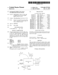
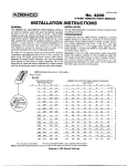
US007677723B2
(12) Ulllted States Patent
(10) Patent N0.:
Howell et al.
US 7,677,723 B2
(45) Date of Patent:
Mar. 16, 2010
(54)
EYEGLASSES WITH A HEART RATE
MONITOR
2,638,532 A
2,794,085 A
5/1953 Brady
5/1957 De Angells
(75)
Inventors: Thomas A. Howell, Palo Alto, CA (US);
David Chao, Saratoga, CA (US); C.
2318511 A
2’830’132 A
12/1957 Ullery et 31'
4/1958 Borg
Douglass Thomas, Campbell, CA (US);
Robert Grant Day, San Francisco, CA
(US); Peter P. Tong, Mountain V1eW, CA
_
(Us)
(Cont1nued)
(73) Assignee: IpVenture, Inc., Los Altos, CA (US)
(*)
Notice:
Subject to any disclaimer, the term of this
patent is extended or adjusted under 35
FOREIGN PATENT DOCUMENTS
CN
88203065
11/1988
USC 154(b) by 288 days.
(21) Appl. No.: 11/650,626
(Cont1nued)
OTHER PUBLICATIONS
(22) Filed:
Jan. 6, 2007
“:1.5g Dual Axis Micromachined Accelerometer”, Freescale Semi
(65)
Prior Publication Data
Us 2007/0109491 A1
May 17, 2007
conductor, lnc., Motorola Semiconductor Technical Data,
MMA6260Q, 2004,14’ H
Related US. Application Data
(60) Provisional application No. 60/787,850, ?led on Apr.
1, 2006, provisional application No. 60/846,150, ?led
on Sep. 20, 2006, provisional application No. 60/763,
(Cont1nued)
Primary ExamineriHuy K Mai
(57)
ABSTRACT
854, ?led on Jan. 30, 2006.
(51)
Int_ CL
A pair of glasses With a heart-rate monitor according to one
( 200601 )
embodiment. The heart-rate monitor is con? gured to measure
US. Cl. ....................................... .. 351/158-, 351/41
Field of Classi?cation Search ................. .. 351/41,
the heart rate Ofthe user ofthe g lasses. The heart-rate monitor
can include a Sensor With a radiation transmitter and a radia
3 51 / 136, 158; 607/9, 14, 18
tion receiver. The radiation could be infrared radiation. In one
G02C 1/00
( 52 )
(58)
See application ?le for complete Search history,
(56)
R f
Ct d
e erences
1 e
U.S. PATENT DOCUMENTS
320,558
669,949
1,255,265
1,917,745
2,249,572
A
A
A
A
A
6/1885
3/1901
2/1918
7/1933
7/1941
Hull
Underwood
Zachara
Weiss
Lieber
approach, the receiver measures signals transmitted by the
transmitter through a body part of the user to measure the
user’ s heart rate. The sensor could be incorporated in a clip to
clip onto the body part of the user, such as the ear lobe of the
user. In another approach, the receiver measures signals trans
mitted by the transmitter and re?ected by a body part of the
user to measure the user’s heart rate.
26 Claims, 9 Drawing Sheets
US 7,677,723 B2
Page2
2,904,670
3,060,308
3,597,054
3,710,115
4,165,487
U.S. PATENT DOCUMENTS
6,061,580 A
6,091,546 A
A
A
A
A
A
6,091,832
6,115,177
6,132,681
6,154,552
6,176,576
9/1959
10/1962
8/1971
l/1973
8/1979
Calmes
Forfuna
Win18r
Jubb
Corderman
A
A
A
A
B1
4,254,451 A
3/1981 Cochran/1L
6,225,897 B1
4,283,127
4,322,585
4,348,664
4,389,217
4,526,473
4,535,244
4,608,492
4,683,587
4,751,691
8/1981
3/1982
9/1982
6/1983
7/1985
8/1985
8/1986
7/1987
6/1988
6,231,181
6,236,969
6,243,578
6,259,367
6,270,466
6,292,213
6,301,367
6,307,526
6,343,858
A
A
A
A
A
A
A
A
A
4,757,714 A
4,773,095
4,806,011
4,822,160
4,822,161
4,851,686
4,942,629
4962469
4,985,632
5,008,548
A
A
A
A
A
A
A
A
A
Rosenwinkeletal.
Liautaud
Boschettiet al.
Baughman et al.
Zahmlll
Burnham
Burnham
Silverman
Perera
7/1988 PuIdyetaL
9/1988
2/1989
4/1989
4/1989
7/1989
7/1990
10/1990
1/1991
4/1991
5/2000 A1166111116161.
7/2000 sp11Z61
7/2000
9/2000
10/2000
11/2000
1/2001
5/2001 D6y16 6161.
B1
B1
B1
B1
B1
B1
B1
B1
B1
5/2001
5/2001
6/2001
7/2001
8/2001
9/2001
10/2001
10/2001
2/2002
6,349,001 B1
2/2002
6,349,422
6,409,338
6,426,719
6,431,705
6,478,736
6,506,142
6,513,532
6,517,203
6,539,336
Shannon
6,542,081 B2*
4/2003
6,546,101 B1
6,554,763 B1
4/2003 M11116y6161.
4/2003 A1116116 6161.
5/1991
5,036,311 A
5,050,150 A
7/1991 Moran @191
9/1991 Ikeda
2/2002
6/2002
7/2002
8/2002
11/2002
1/2003
2/2003
Swab
Rupp6116161.
Koike
Klein
W6111s161116161.
Jones
B6yd6116161.
Mann
zelman
sp11Z61
s61116g616161.
J6w611
N6g616d6 6161.
L111d611
M61111
116116161.
M611116161.
ZWiCkPr er 91
Bertinger
Tsai
Jimmy
Pearson
Stadlmann
01199191
Bianco et al.
Gar
5,020,150 A
B1
B1
B1
B1
B1
B2
B2
B1
B1
s111111116116161.
VOSSlef
B61611 6161.
K6161j6w 6161.
6166116161.
2/2003 Blumet 31,
3/2003 VOCk 6161.
161611 ....................... .. 340/575
5,093,576 A
3/1992 Edmond et a1.
6,619,799 B1
9/2003 Blum et 31,
5,148,023 A
5,151,600 A
5,161,250 A
9/1992 Hayashiet al.
9/1992 B111Ck
11/1992 16111121 9191
6,629,076 B1
6,721,962 B1
6,729,726 B2
9/2003 Haken
4/2004 P616116
5/2004 M111616161.
5,172,256 A
5,306,917 A
12/1992 Sethofer et al.
4/1994 Black et a1.
5,353,378
5359370
5,367,345
5,379,464
5,382,986
5,394,005
5,452,480
5,455,640
5,457,751
5,500,532
D369,167
5,510,981
5,513,384
5,533,130
5,581,090
5,585,871
5,589,398
5,590,417
5,608,808
5,634,201
5,673,692
5,686,727
5,715,323
5,737,436
5,900,720
10/1994 Hoffman etal.
10/1994 Mugnier
6,736,759 B1
6,764,194 B1
6,792,401 B1
5/2004 Stubbs et a1‘
7/2004 Cooper
9/2004 Nigro etal,
6,912,386 B1
6/2005 1111111561g 6161.
A
A
A
A
A
A
A
A
A
A
S
A
A
A
A
A
A
A
A
A
A
A
A
A
A
5,941,837 A
5,946,071 A
11/1994
1/1995
1/1995
2/1995
9/1995
10/1995
10/1995
3/1996
4/1996
4/1996
4/1996
7/1996
12/1996
12/1996
12/1996
12/1996
3/1997
5/1997
10/1997
11/1997
2/1998
4/1998
5/1999
8/1999
da Silva
Schlegeret al.
Black et a1.
Brown etal.
Ryden
Geltsikov
Such
Kozicki
Hanson et al.
BergeretalBrennan et al.
Staton
Goudjil
Linden
Krause eta1~
Rydbeck
da Silva
Mooring
39111112991111
Reenstra eta1~
Walker
Boyden e191
Kallman e191
Amano etal
8/1999 Feldman
6,929,365
6,947,219
7,013,009
7,031,667
7,059,717
7,073,905
7,192,136
7,255,437
7,265,358
7,274,292
7,312,699
7,331,666
7,429,985
7,376,238
2001/0005230
2002/0017997
2002/0081982
2002/0084990
2002/0089639
2002/0090103
2002/0098877
2002/0109600
2002/0140899
2002/0197961
B2
B1
B2
B2
B2
B2
B2
B2
B2
B2
B2
B2
B2
B1
A1
A1
A1
A1
A1
A1
A1
A1
A1
A1
8/2005
9/2005
3/2006
4/2006
6/2006
7/2006
3/2007
8/2007
9/2007
9/2007
12/2007
2/2008
9/2008
5/2009
$16615 6161.
()u
Warren
Horiguchi
B16611
Dapra’
116w6116161.
116w6116161.
Fontaine
V6111616161.
Chomenky
$16615 6161.
K11111116 6161.
R1v6s6161.
6/2001 IShikaWa
2/2002 F611<6W11Z
6/2002 s611w611Z 6161.
7/2002 P6161s611,111
7/2002
7/2002
7/2002
8/2002
10/2002
12/2002
s16111616161.
c611s16,J1.
GleZefIIlaIl
M611116161.
BluIIl 6161.
W611611
2003/0018274 A1*
1/2003
1616166111 6161. ......... .. 600/500
59661746
5,980,037
5,988,812
5,992,996
A
A
A
A
10/1999
11/1999
11/1999
11/1999
Reedy e191Conway
Wingate
Sawyer
2003/0022690
2003/0032449
2003/0062046
2003/0063591
A1
A1
A1
A1
1/2003
2/2003
4/2003
4/2003
B6yd6 6161.
GiObbi
WeiSIIlaIlIl
L61111g 6161.
5,995,592
6,010,216
6,013,919
6,028,627
6,046,455
6,060,321
A
A
A
A
A
A
11/1999
1/2000
1/2000
2/2000
4/2000
5/2000
Shirai e191
Jesiek
s611116161616161.
11611116661161
R11516161.
116v611<6
2003/0065257
2003/0067585
2003/0068057
2003/0226978
2004/0000733
2004/0063378
A1
A1
A1
A1
A1
A1
4/2003
4/2003
4/2003
12/2003
1/2004
4/2004
M611116161.
M111616161.
M111616161.
R11516161.
sw6b 6161.
NelSOIl
US 7,677,723 B2
Page 3
2004/0096078
2004/0150986
2004/0156012
2004/0157649
2004/0160571
2004/0160572
2004/0160573
2005/0067580
2005/0213026
2005/0230596
A1
A1
A1
A1
A1
A1
A1
A1
A1
A1
5/2004 Lin
“Heart Rate Monitors”, http://www.healthgoods.com, downloaded
8/2004 Chang
Dec. 4, 2004.
“How is the UV IndeX Calculated”, SunWise Program, US. Envi
8/2004
8/2004
8/2004
8/2004
8/2004
3/2005
9/2005
10/2005
Jannardetal.
Jannardetal.
Jannard
Jannard
Jannardetal.
Fontaine
Da Pra’
Howell et al.
2005/0238194 A1*
10/2005
Chornenky ............... .. 381/381
“Oakley Thump: Sunglasses Meet MP3 Player”, with Image, http://
2005/0248717
2005/0248719
2005/0264752
2006/0001827
2006/0003803
2006/0023158
2006/0107822
2007/0030442
2007/0046887
11/2005
11/2005
12/2005
1/2006
1/2006
2/2006
5/2006
2/2007
3/2007
Howell et al.
Howell et al.
Howell et al.
Howell et al.
Thomas et al.
Howell et al.
Bowen
Howell et al.
Howell et al.
news.designtechnica.com/article4665.htrnl, Jul. 13, 2004.
“Personal UV monitor,” OptIcs.org, http://opticsorg/articles/news/
6/6/7/1 (downloaded Dec. 20, 2003), Jun. 9, 2000, pp. 1-2.
“SafeSun Personal Ultraviolet Light Meter”, http://
healthchecksystems.com/safesun.htm, downloaded Jul. 12, 2004,
A1
A1
A1
A1
A1
A1
A1
A1
A1
2007/0098192 A1
2007/0186330
2007/0208531
2007/0270663
2007/0271065
2007/0271116
2007/0271387
2008/0068559
2008/0132382
A1
A1
A1
A1
A1
A1
A1
A1
2008/0144854 A1*
2008/0262392 A1
ronmental Protection Agency, http://www.epa.gov/sunwise/uvcalc.
html, downloaded Oct. 14, 2004, pp. 1-2.
“Industrial UV Measurements”, APA Optics, Inc., http://www.
apaoptics.com/uv/, downloaded Jul. 12, 2004, p. 1.
“Motorola and Oakley Introduce First Bluetooth Sunglasses-Cutting
Edge RAZRWIre Line Offers Consumers On-The-Go Connections”,
Motorola Mediacenter-Press Release, Feb. 14, 2005, pp. 1-2.
pp. 1-4.
“SafeSun Personal UV Meter”, Introduction, OptlX Tech Inc., http://
www.safesun.com, downloaded Feb. 5, 2004, pp. 1-2.
SafeSun Personal UV Meter, features, OptiX Tech Inc., http://www.
safesun.com/features.html, downloaded May 1, 2004, pp. 1-2.
5/2007 Sipkema
8/2007
9/2007
11/2007
11/2007
11/2007
11/2007
3/2008
6/2008
6/2008
“Sharper ImageiThe FM Pedometer”, e-Corporate Gifts.com,
Howell et al.
Darley et al.
Ng et al.
Gupta et al.
Wysocki et a1.
Lydon et al.
Howell et al.
SturZer
http://www.e-corporategifts.com/sr353.html, downloaded Jan. 22,
2005, pp. 1-2.
“Sun UVTM Personal UV Monitor”, APA Optics, Inc., http://www.
apaoptics.com/sunuv/uvfacts.html, downloaded Dec. 20, 2003, pp.
1-3.
“Ultraviolet Light and Sunglasses”, Oberon’s Frequently Asked
Questions,
Abreu ....................... .. 381/74
10/2008 Ananny et a1.
“Ultraviolet Light Sensor”, Barrett & Associates Engineering, http://
www.barrettengineering.com/projectiuvshtm, downloaded Feb. 5,
FOREIGN PATENT DOCUMENTS
CN
CN
EP
FR
GB
JP
JP
JP
JP
JP
JP
JP
TW
W0
W0
W0
W0
W0
W0
W0
89214222.7
90208199.3
1134491
2530039
1467982
58-113912
58-113914
02-181722
09-017204
10-161072
2000-039595
2002 341059
484711
WO 97/12205
WO 99/50706
WO 02/06881
W0 03/069394
W0 03/100368
WO 2004/012477
WO 2004/025554
A2
A1
A
A1
A2
A1
A1
A2
A1
http://www.oberoncompany.com/OBEnglish/FAQUV.
html, downloaded Feb. 5, 2004, pp. 1-2.
2004, pp. 1-3.
“Ultraviolet Radiation (UVR)”, Forum North, Ontario Ministry of
3/1990
11/1990
9/2001
1/1984
3/1977
7/1983
7/1983
7/1990
1/1997
6/1998
2/2000
11/2002
6/2001
4/1997
10/1999
1/2002
8/2003
12/2003
2/2004
3/2004
Labour,
http://www3.mb.sympatico.ca/~ericc/
ULTRAVIOLET%20RADIATION.htm, downloaded Feb. 5, 2004,
pp. 1-6.
“What Are Gripples?”, Gripping Eyewear, Inc., http://www.grip
pingeyewearcom/whatare.htrnl, downloaded Nov. 2, 2005.
“With Racing Heart”, Skaloud et al, GPS World, Oct. 1, 2001, http://
www. gpsworld.com/gp sworld/content/printContentPopup.
jsp?id:1805, pp. 1-5.
Abrisa Product Information: Cold Mirrors, Abrisa, date unknown, p.
1.
Abrisa Product Information: Commercial Hot Mirror, Abrisa, date
unknown, p. 1.
Alps Spectable, Air Conduction Glass, Bone Conduction Glass,
htt;://www.alps-Inter.com/spec.htrn, downloaded Dec. 10, 2003, pp.
1-2.
Altimeter and Compass Watches, http://store.yahoo.com/
snowshacldaltimeter-watches.htrnl, downloaded May 3, 2004, pp.
1-2.
Bone Conduction Headgear HG16 Series, “Voiceducer,” http://www.
ternco-j.cojp/html/English/HG16.html, downloaded Dec. 10, 2003,
pp. 1-3.
OTHER PUBLICATIONS
“APA Announces Shipment of the SunUVTM Personal UV Monitor”,
Press Release, Nov. 7, 2003, pp. 1-3.
Carnoy, David, “The Ultimate MP3 Player for Athletes? Could be”,
CNET Reviews, May 14, 2004, pp. 1-4.
Clifford, Michelle A., “Acccelerometers Jump into the Consumer
“Camera Specs Take Candid Snaps”, BBC News, Sep. 18, 2003, pp.
Goods Marker”, Sensors Online, http://www.sensorsmag.com, Aug.
1-3.
2004.
“Cardo Wireless Attaching Clips and Wearing Headset”, Cardo Sys
tems, Inc., http://www.cardowireless.com/clips.php, downloaded
Cool Last Minute Gift Ideas!, UltimateFatBurner Reviews and
Nov. 27, 2004, pp. 1-3.
“Environmental Health Criteria 14: Ultraviolet Radiation”, Interna
tional Programme on Chemical Safety, World Health Organization
Geneva, 1979 http://www.ichem.org., pp. 1-102.
“Eyetop, Product-Features”, eyetop eyewear, eyetop belt worn,
loaded May 10, 2005, pp. 1-3.
http://www.eyetop.net/products/eyetop/features.asp.,
downloaded
Articles, http://www.ultimatefatburner.com/gift-ideas.htrnl, down
Comfees.com, Adjustable Sports Band Style No. 1243, http://shop.
store.yahoo.com/comfees/adsporbanstyhtml, downloaded Apr. 18,
2003, pp. 1-2.
DiXen, Brian, “ear-catching”, Supertesten, Mobil, date unknown, pp.
37-41.
Nov. 6, 2003, pp. 1-2.
“Exclusive Media Event Marks Debut of Oakley Thump: World’s
Global Solar UV Index, A Practical Guide, World Health Organiza
tion, 2002, pp. 1-28.
First Digital Audio Eyewear”, Oakley Investor Relations, Press
Release, Nov. 15, 2004, pp. 1-2.
Grobert, Sam, “Digit-Sizing Your Computer Data”, News Article,
Sep. 2004 p. 1.
US 7,677,723 B2
Page 4
Life Monitor Vl.l, Rhusoft Technologies Inc., http://www.rhusoft.
SportLine Fitness Pedometer-Model 360, UltimateFatBurner
com/lifemonitor/, Mar. 1, 2003, pp. 1-6.
Superstore, http://www.ultimatefatburner-store.com/aci004html,
Manes, Stephen, “Xtreme Cam”, Forbes Magazine, Sep. 5, 2005, p.
downloaded May 10, 2005, pp. l-2.
Steele, Bonnie G. et al., “Bodies in motion: Monitoring daily activity
96.
Mio, PhyslCal, http://www.gophysical.com/, downloaded Jan. 27,
2004, 5 pages.
Monitoring Athletes Performancei2002 Winter Olympic News
from KSL, Jan. 23, 2002, http://2002.ksl.com/news-3885i.php, pp.
l-3.
Niwa, “UV Index Information”, http://www.niwa.cri.nZ/services/
and exercise with motion sensors in people with chronic pulmonary
disease”, VA Research & Development, Journal of Rehabilitation
Research & Development, vol. 40, No. 5, Sep./Oct. 2003, Supple
ment 2, pp. 45-58.
Stevens, Kathy, “Should I Use a Pedometer When I Walk?”,
uvoZone/uvi-info, downloaded Jul. 15, 2004, pp. l-2.
Parkka, Juha, et al., “A Wireless Wellness Monitor for Personal
Healtheon/WebMD, Apr. 14, 2000.
Sundgot, Jyargen “Znd-gen Motorola Bluetooth headset”, InfoSync
World, Mar. 1, 2003, http://www.infosync.no/news/2002/n/284l.
Weight Management”, VTT Information Technology, Tampere, Fin
html, pp. l-2.
land, date unknown, p. l.
Pedometer, Model HJ-l l2, Omron Instruction Manual, Omron
Healthcare, Inc., 2003, pp. l-27.
SunSensors, Segan Industries, Inc., http://www.segan-ind.com/
PNY Announces Executive Attaché USB 2.0 Flash Drive and Pen
apaoptics.com/sunuv/models.html, downloaded Dec. 20, 2003.
SunUVTM, Personal UV Monitor User’s Guide, APA Optics, Inc.,
Series, Press Release, PNY Technologies, Las Vegas, Jan. 8, 2004,
sunsensor.htm, downloaded Feb. 5, 2004, pp. l-3.
SunUVTM, Personal UV Monitor, APA Optics, Inc., http://www.
pp. l-2.
2003 pp. l-52.
PNY Technologies, “Executive Attaché” http://www.pny.com/prod
ucts/?ash/execattacheasp downloaded Nov. 16, 2005.
Polar WM4l and 42 weight management monitor, http://www.
simplysports/polar/weightimanagement/wm4 l -42 .htm,
down
Talking Pedometer, Sportline, Inc., date unknown.
loaded Jan. 28, 2004, pp. l-3.
Questions Answers, Pedometercom, http:/www.pedometer.com,
downloaded May 5, 2005.
RaZrWire, Motorola, 2005, 1 page.
SafeSun Personal UV Meter, Scienti?c Data, Optix Tech Inc., http://
www.safesun.com/ scienti?c .htrnl, downloaded May I, 2003, pp. l-3.
SafeSun Sensor, User’s Manual, Optix Tech Inc., date unknown.
SafeSun, Personal UV Meter, “Technical Speci?cations”, Optix Tech
Inc., http://www.safesun.com/technical.html, downloaded Jul. 12,
2004, pp. l-2.
SafeSun, Personal UV Meter, Experiments, Optix Tech Inc., http://
www.safesun.com/experimentshtml, downloaded Feb. 5, 2004, pp.
l-2.
Shades of Fun, Blinking Light Glasses, http://www.shadesoffun.
com/Nov/Novpgs-l4.html, downloaded Jul. 9, 2005, pp. l-4.
Top Silicon Pin Photodiode, PD93-2lC, Technical Data Sheet,
Everlight Electronics Co., Ltd., 2004, pp. l-9.
UV Light Meter, UVA and UVB measurement, UV-340, Instruction
Manual, Lutron, date unknown, pp. l-5.
UV-Smart, UVNB Monitor, Model EC-960-PW, Instruction
Manual, Tanlta Corporation of America, Inc., downloaded Nov. 16,
2001.
Vitaminder Personal Carb Counter with Convenient Key Chain, date
unknown, pp. l-4.
Nellcor OxiMax, Sensor Selection Guide, Tyco Healthcare, copy
right 2002 Tyco Healthcare, Oct. 2002, 12 pages.
NELLCORTM Oximax SensorsTM, Tyco Healthcare ECE, http://
www.tycohealth-ece.com/index.php?folder:53&article:l00,
downloaded Nov. 29, 2006 pp. l-5.
Principles of Pulse Oximetry Technology, copyright 2002 Oximeter.
org, http://www.oximeter.org/pulseox/principleshtm, downloaded
Jul. 18, 2006, pp. l-3.
* cited by examiner
US. Patent
Mar. 16, 2010
Sheet 1 019
US 7,677,723 B2
US. Patent
Mar. 16, 2010
Sheet 2 of9
oom
vow
0ZmM4mu
US 7,677,723 B2
US. Patent
Mar. 16, 2010
Sheet 4 of9
US 7,677,723 B2
0mm
mm.2;
US. Patent
Mar. 16, 2010
Sheet 5 of9
US 7,677,723 B2
mwo
an.5
<51 5l
hQ8
W
8w mmm A1_
LmN8%
\w
U
w
O
1 \k__
1mg
wlwmw
on.9“.
US. Patent
W»
Mar. 16, 2010
Sheet 6 0f9
706
/
700
Fig. 4
US 7,677,723 B2
US. Patent
Mar. 16, 2010
Sheet 7 0f 9
US 7,677,723 B2
US. Patent
Mar. 16, 2010
Sheet 8 of9
US 7,677,723 B2
US. Patent
om“
own
Mar. 16, 2010
Sheet 9 of9
NE
§\\\\\\\\\\\\\\\\\\
won
om“
US 7,677,723 B2
US 7,677,723 B2
1
2
In addition, this application is related to each of: (i) US.
EYEGLASSES WITH A HEART RATE
MONITOR
patent application Ser. No. 10/822,218, ?led Apr. 12, 2004,
and entitled “EYEGLASSES FOR WIRELESS COMMUNI
CATIONS,” Which is hereby incorporated herein by refer
ence; (ii) US. patent application Ser. No. 10/964,011, ?led
Oct. 12, 2004, and entitled “TETHERED ELECTRICAL
COMPONENTS FOR EYEGLASSES,” Which is hereby
CROSS-REFERENCE TO RELATED
APPLICATIONS
This application is related to US. patent application Ser.
No. 11/183,256, ?led Jul. 15, 2005, and entitled “EYE
GLASSES WITH ELECTRICAL COMPONENTS,” Which
is hereby incorporated herein by reference, Which in turn is a
continuation-in-part of US. patent application Ser. No.
10/964,011, ?led Oct. 12, 2004, and entitled “TETHERED
ELECTRICAL COMPONENTS FOR EYEGLASSES,”
incorporated herein by reference; (iii) US. patent application
Ser. No. 11/006,343, ?led Dec. 7, 2004, and entitled
“ADAPTABLE COMMUNICATION TECHNIQUES FOR
ELECTRONIC DEVICES,” Which is hereby incorporated
herein by reference; (iv) US. patent application Ser. No.
11/078,855, ?led Mar. 11, 2005, and entitled “EYEWEAR
WITH RADIATION DETECTION SYSTEM,” Which is
Which is hereby incorporated herein by reference, Which in
hereby incorporated herein by reference; (v) US. patent
turn claims priority to each of: (i) US. Provisional Patent
application Ser. No. 11/078,857, ?led Mar. 11, 2005, and
Application No. 60/509,631, ?led Oct. 9, 2003, and entitled
entitled “RADIATION MONITORING SYSTEM,” Which is
“TETHERED ELECTRICAL COMPONENTS FOR EYE
hereby incorporated herein by reference; (vi) US. patent
GLASSES,” Which is hereby incorporated herein by refer
ence; (ii) US. Provisional Patent Application No. 60/527,
565, ?led Dec. 6, 2003, and entitled “ADAPTABLE
COMMUNICATION TECHNIQUES FOR ELECTRONIC
application Ser. No. 11/183,269, ?led Jul. 15, 2005, and
20
DEVICES,” Which is hereby incorporated herein by refer
ence; (iii) US. Provisional Patent Application No. 60/562,
798, ?led Apr. 15, 2004, entitled “EYEWEAR WITH
ULTRAVIOLET DETECTION SYSTEM,” and Which is
No. 11/183,283, ?led Jul. 15, 2005, and entitled “EVENT
25
HEARING ENHANCED AND OTHER AUDIO SIGNAL
entitled “ELECTRICAL COMPONENTS FOR USE WITH
EYEWEAR, AND METHODS THEREFOR,” and Which is
30
WITH A CLOCK OR OTHER ELECTRICAL COMPO
US. patent application Ser. No. 11/183,276, ?led Jul. 15,
ELECTRICAL COMPONENT,” and Which is hereby incor
2005, and entitled “EYEGLASSES WITH ACTIVITY
35
WEAR, AND METHODS THEREFOR,” and Which is
SUPPORTING AFTER MARKET ELECTRICAL COM
hereby Incorporated herein by reference.
PONENTS,” Which is hereby incorporated herein by refer
40 ence.
BACKGROUND OF THE INVENTION
Which is hereby incorporated herein by reference; (ii) US.
Provisional Patent Application No. 60/ 620,238, ?led Oct. 18,
2004, entitled “EYEGLASSES WITH HEARING
There are various devices to measure heart rates. For
45
ENHANCED AND OTHER AUDIO SIGNAL-GENERAT
ING CAPABILITIES,” and Which is hereby incorporated
herein by reference; (iii) US. Provisional Patent Application
No. 60/647,836, ?led Jan. 31, 2005, and entitled “EYE
MONITORING,” Which is hereby incorporated herein by
reference; and (xi) US. Provisional Patent Application No.
1 1/ 580,222, ?led Oct. 11, 2006, and entitled “EYEGLASSES
“ELECTRICAL COMPONENTS FOR USE WITH EYE
US. patent application Ser. No. 11/183,256 also claims
priority to each of: (i) US. Provisional Patent Application No.
60/618,107, ?led Oct. 12, 2004, and entitled “TETHERED
ELECTRICAL COMPONENTS FOR EYEGLASSES,”
GENERATING CAPABILITIES,” Which is hereby incorpo
rated herein by reference; (iX) U. S. patent application Ser. No.
1 1/ 183,263, ?led Jul. 15, 2005, and entitled “EYEGLASSES
NENT,” Which is hereby incorporated herein by reference; (X)
entitled “EYEGLASSES WITH A CLOCK OR OTHER
porated herein by reference; and (vi) US. Provisional Patent
Application No. 60/605,191, ?led Aug. 28, 2004, entitled
EYEGLASSES,” Which is hereby incorporated herein by ref
erence; (viii) US. patent application Ser. No. 11/183,262,
?led Jul. 15, 2005, and entitled “EYEGLASSES WITH
hereby incorporated herein by reference; (iv) U.S. Provi
sional PatentApplicationNo. 60/583,169, ?led Jun. 26, 2004,
hereby incorporated herein by reference; (v) US. Provisional
Patent Application No. 60/592,045, ?led Jul. 28, 2004,
entitled “EYEWEAR SUPPORTING AFTER-MARKET
ELECTRICAL COMPONENTS,” Which is hereby incorpo
rated herein by reference; (vii) U.S. patent application Ser.
example, one approach depends on Wrapping a band across a
person’s chest. Electrodes in the band can sense the person’s
heart beat and Wirelessly transmit the measured signals to a
receiver. This approach can be quite inconvenient because the
50
GLASSES WITH HEART RATE MONITOR,” Which is
person has to Wear a band across his chest in order to get the
necessary measurements.
Another approach to measure heart beat is to clip an infra
red sensor onto a person’s ?nger. The sensor is connected to
hereby incorporated herein by reference; and (iv) U.S. Pro
visional Patent Application No. 60/647,826, ?led Jan. 31,
2005, and entitled “EYEWEAR WITH ELECTRICAL
a machine through a Wire. This approach is unsatisfactory if
COMPONENTS,” Which is hereby incorporated herein by
one intends to remain active, or to use one’s hands While
55
reference.
It should be apparent from the foregoing that there is still a
The application also claims priority to each of: (i) US.
Provisional Patent Application No. 60/787,850, ?led Apr. 1,
need for an accurate heart rate monitor that is convenient to
use for a person Who may be in motion.
2006, and entitled “EYEGLASSES WITH A HEART RATE
MONITOR,” Which is hereby incorporated herein by refer
ence; (ii) US. Provisional Patent Application No. 60/846,
150, ?led Sep. 20, 2006, and entitled “EYEGLASSES WITH
ACTIVITY MONITORING,” Which is hereby incorporated
herein by reference; and (iii) US. Provisional Patent Appli
cation No. 60/763,854, ?led Jan. 30, 2006, and entitled “HAT
WITH A RADIATION SENSOR,” Which is hereby incorpo
rated herein by reference.
measurements are taken.
60
SUMMARY OF THE INVENTION
In one embodiment, the present invention provides a heart
rate sensor attached to, integral With or tethered to a pair of
65
glasses. When Worn, the pair of glasses is in a stable position
relative to the user. The glasses serve as a good platform for
heart rate sensing.
US 7,677,723 B2
4
3
In different embodiments, the glasses could be sunglasses,
prescription glasses, reading glasses, or sWimming or skiing
In one embodiment, the sensor can be an infrared transmit
ter With an infrared detector on a clip. The clip could be
tethered to a temple of the glasses. The user can attach the clip
goggles. In one embodiment, there could be a strap, cord or
to her ear lobe to measure her heart rate. With the ear lobe
lanyard attached to the glasses. In another embodiment, a
being adjacent to the glasses, the length of the Wire tethering
heart rate monitor or sensor is attached or tethered to, or
the clip to the temple could be relatively short. A short Wire is
integral With, the strap, cord or lanyard. In one embodiment,
more convenient for the user than a long Wire, particularly if
the user has to move around. Also, the degree of movement of
the clip relative to the ear lobe typically is less if the Wire is
a heart rate monitor or sensor is attached or tethered to, or
integral With, an apparatus Wearable to the head of the user.
Examples of such an apparatus include hats, headbands and
helmets.
short, Which could lead to more accurate measurements.
arm or semi-rigid arm or cable could enhance the stability of
Other aspects and advantages of the present invention Will
become apparent from the folloWing detailed description,
Which, When taken in conjunction With the accompanying
draWings, illustrates by Way of example the principles of the
the clip relative to the glasses.
invention.
In another embodiment, instead of a Wire, the clip could be
electrically coupled to the glasses through an adjustable
mechanical arm, or a semi-rigid arm or cable. The mechanical
In one embodiment, there could be an output device to
provide outputs to the user, such as regarding her heart rate.
For example, the output device could be based on audio or
visual capabilities or both. In the embodiment With visual
outputs, the output device could be located at the inside,
peripheral position of the glasses, such as close to a hinge of
the glasses, linking a temple to a lens holder.
BRIEF DESCRIPTION OF THE DRAWINGS
FIG. 1 shoWs a person Wearing a pair of glasses With a heart
20
In one embodiment, there could be a Wireless transceiver in
the glasses to send signals regarding the monitored heart rate
to a portable or handheld device carried by the user for addi
25
tional processing and/ or display.
such as a stationary bike or a treadmill. The signals could be
30
the speed of the treadmill based on the monitored heart rate.
In another embodiment, the glasses further include a
memory device storing, for example, exercise programs or
songs. The memory device could be integral With or attached
to the glasses. The user could be folloWing a stored Workout
program, Which could give the user commands, such as,
“Keep running at the same pace for the next 3 minutes”; or
“Keep running at the same pace until I tell you to stop.”At the
35
end of the Workout program, the user could be noti?ed of the
40
doWnloaded to another device to be displayed for a doctor. In
45
a semi-rigid arm or cable to a temple of a pair of glasses
according to an embodiment of the invention.
FIG. 7 shoWs a heart rate sensor that is based on measuring
re?ected signals according to an embodiment of the inven
tion.
Same numerals in FIGS. 1-7 are assigned to similar ele
ments in all the ?gures. Embodiments of the invention are
discussed beloW With reference to FIGS. 1-7. HoWever, those
skilled in the art Will readily appreciate that the detailed
description given herein With respect to these ?gures is for
explanatory purposes as the invention extends beyond these
limited embodiments.
DESCRIPTION OF THE INVENTION
another example, if the monitored heart rate exceeds certain
predetermined threshold, an alert signal Would be automati
In one embodiment, a pair of glasses for a user has a heart
cally sent to a health care provider for the user.
In yet another embodiment, the heart rate sensor or monitor
rate (heart beat) monitor. The heart rate monitor can be par
50
tially or fully embedded in the eyeglasses. For example, the
heart rate monitor can be substantially embedded in a temple
of the eyeglasses. In another embodiment, the heart rate
monitor can be coupled (either permanently or temporarily)
to the eyeglasses.
replaceable temple tip. This alloWs the user to acquire the
sensor or monitor subsequent to getting a pair of glasses.
In one embodiment, the glasses further include at least a
portion of other electronic devices, such as a pedometer or a
temperature sensor. The outputs from the different devices
could be combined to help the user. For example, if the user
ment of the invention.
FIG. 5 shoWs a heart rate sensor clip being attached through
an adjustable mechanical arm to a temple of a pair of glasses
according to an embodiment of the invention.
FIG. 6 shoWs a heart rate sensor clip being attached through
number of calories burned, distance traveled, etc.
In another embodiment, the heart rate monitor is for moni
toring the user’s certain health conditions, such as to help the
user With irregular heart beat. For example, the glasses keep
track of the user’s heart rate, Which could be subsequently
could be designed as an aftermarket product, such as designed
in or designed to be attachable to a replaceable temple or
FIG. 2 shoWs a pair of glasses With LED as outputs accord
ing to an embodiment of the invention.
FIGS. 3A-D shoW examples of circuits to measure the heart
rate of a user according to different embodiments of the
invention.
FIG. 4 shoWs a heart rate sensor clip being attached to the
tip of a temple of a pair of glasses according to an embodi
In another embodiment, signals regarding the monitored
heart rate can be Wirelessly received by a non-portable device,
used to adjust the operations of the device, such as changing
rate sensor according to an embodiment of the invention.
55
In one embodiment, the heart rate monitor can include an
infrared sensor (or IR sensor) and processing circuitry. Using
measurements from the infrared sensor, the processing cir
cuitry can determine the user’s heart rate. The eyeglasses can
constantly experiences irregular heart beat, the pedometer
also include one or more output devices, such as a speaker or
the user has been active or at rest at the onset of an irregular 60 beeper, for audio output, and/or a display for visual output.
With the heart rate monitor Would be able to better indicate if
FIG. 1 illustrates a pair of eyeglasses 500 having heart rate
monitoring capabilities according to one embodiment. The
pair of eyeglasses 500 includes left and right temples 502 and
left and right lens holders 504.
heart beat.
In one embodiment, the heart rate sensor is based on mea
suring re?ected radiation. The sensor can be con?gured to
maintain substantially a constant distance to the position on
the skin that the sensor is measuring. Such a sensor could
include an infrared transceiver. In one example, such a sensor
is at a nose pad ofa pair of glasses.
65
A rearWard temple portion 506 (e. g., temple tip region) of
at least one of the temples 502 includes an electrical connec
tor 508. As an example, the electrical connector 508 is a
US 7,677,723 B2
5
6
standard connector such as a 3 .5 mm mini-phone connector or
In one embodiment, the circuits measure the pulse of the user
a bus connector (e.g., USB connector). In FIG. 1, the connec
tor is depicted to be at the end of a temple. The connector or
by stabiliZing the outputs from the IR sensor (such as With a
feedback loop), ?ltering out the DC offset and amplifying the
outputs to extract the pulse signals.
a different connector could be at other locations as described
in related applications, Which have been incorporated by ref
erence. The electrical connector 508 enables the eyeglasses
500 to easily connect With other electrical devices, such as a
FIG. 3A illustrates an example of an input circuit 600. The
input circuit 600 uses a feedback loop to stabiliZe the outputs
from an infrared LED 602, Which radiates infrared to be
computing device.
received by a photodiode 604. The negative terminal of the
In addition, the eyeglasses can be coupled to a clip 510
having an infrared (IR) transmitter 511 and an IR receiver 512
photodiode 604 is connected to a voltage sourceV, such as 4.5
volts. The positive terminal of the photodiode 604 is con
on opposite sides of one end of the clip 510. In one embodi
ment, an IR sensor includes the IR transmitter 511 and the IR
receiver 512.
nected to a loW-pass ?lter With a resistor 606, such as 100 K9,
and a capacitor 608, such as 0.22 uf, in parallel. The loW pass
?lter has a cut-off frequency of 7 HZ. The other end of the
loW-pass ?lter is connected to a voltage source —V, such as
—4.5 volts. The cathode terminal of the photodiode is con
nected through a resistor 612, such as 1 M9, to the negative
input of an operational ampli?er (“opamp”) 610, such as a
LM324. The positive input of the opamp 610 is connected to
In operation, the clip 510 is clipped to a body part of the
user, such as one of the user’ s ears. Different parts of the ears
could be clipped, such as the ear lobe (as illustrated in FIG. 1)
or the upper portion 509 of the person’ s ear. During measure
ment, at least a portion of the IR radiation from the transmitter
511 transmits through the body part that is clipped, and is
received by the IR receiver 512 to be measured. For example,
20
When an ear lobe is clipped as depicted in FIG. 1, the ear lobe
is sandWiched betWeen the IR transmitter 511 and the IR
receiver 512.
The IR sensor is electrically connected to processing cir
cuitry. In one embodiment, the processing circuitry can be at
least partially embedded in the eyeglasses (e.g., in at least one
of the temples), and is electrically connected to the IR sensor
through a cable 514. Alternatively, the cable 514 could have
positive terminal of the infrared LED 602, Whose negative
25
30
FIG. 3B illustrates an example of a tWo-pole loW pass ?lter
630. Through a ?rst loW pass ?lter With a cutoff frequency of
electrical connectors When needed.
light source (eg a red LED) and a light receiver (eg a light
photodiode). In this embodiment, the heart rate sensor moni
tors heart rate by a combination of IR and red light.
16 HZ, the signals S1 are received by the positive input of an
35
opamp 636, such as a LM324. The loW pass ?lter has a resistor
632, such as 1 M9, connected to a capacitor 634, such as 0.01
pf, and then to ground. The junction of the resistor 632 and the
capacitor 634 is connected to the positive input of the opamp
636. The negative input and the feedback loop of the opamp
40
636 have another loW pass ?lter, also With a cut off frequency
of 16 HZ. This loW pass ?lter includes tWo resistors and a
The eyeglasses 500 can also include at least one sWitch 516
and one or more output devices, Which could be visual indi
cators. The sWitch 516 can serve as a start sWitch. In one
embodiment, visual indicators, as shoWn in FIG. 2, can be
located on the interior of a lens holder, such as the left lens
holder 504. In another embodiment, visual indicators are
photodiode 604 to be about the center of its operating range.
In one example, the signals S1 are about 0.2 volts:0.0l volt.
The pulse signals substantially vary betWeen the 10.01 volt.
be electrically connected With the processing circuitry via
In one implementation, the clip 510 is a small spring-clip,
the IR transmitter 511 is an IR LED, and the IR receiver 512
is a silicon photodiode.
In another embodiment, the IR sensor further includes a red
terminal is connected to ground through a resistor 618, such
as 1809. The output ofthe opamp 610 is designated as S1. In
one embodiment, the opamp 610 changes or modulates the
output from the LED 602 so as to keep the signals from the
an electrical connector at one end that can removably couple
to the electrical connector 508 at the glasses. This Would
alloW the IR sensor to be detachable from the glasses, and to
ground. The negative input of the opamp 610 is also con
nected to its output through another loW pass ?lter, With a
cutoff frequency of 3.4 HZ. This loW pass ?lter has a resistor
616, such as 10 M9 in parallel With a capacitor 614, such as
0.005 pf. The output of the opamp 610 is connected to the
45
capacitor. One resistor 642, such as 1 M9, is connected from
the negative input of the opamp 636 to ground. Another
resistor 638, such as 1 M9, in parallel With the capacitor 640,
such as 0.01 pf, is connected betWeen the negative input and
the output of the opamp 636. The signals at the output of the
located at relatively inconspicuous locations that could be
seen by the user Without taking the glasses off. For example,
opamp 636 are designated as S2.
the visual indicators canbe located on the interior of a temple,
close to its end that connects With the corresponding lens
holder. In one embodiment, the visual indicators are LEDs.
Which at least serves to remove constant or DC signals from
FIG. 3C illustrates an example of a bandpass ?lter 650,
50
For example, the eyeglasses 500 include a ?rst LED 518 (e.g.,
green LED) and a second LED 520 (e.g., red LED).
FIGS. 3A-3D shoWs examples of circuits to measure the
pulse of a user according to an embodiment. The examples
serve as illustrations, and other types of circuits could be
used. In general, the circuits include an infrared LED and a
pass ?lter has a capacitor 652, such as 0.22 pf, connected to a
55
feedback loop of the opamp 656 have a loW pass ?lter, With a
cut off frequency of 16 HZ. This loW pass ?lter includes tWo
resistors and a capacitor. One resistor 662, such as 10 K9, is
60
betWeen the photodiode and the LED. If the distance betWeen
the photodiode and the LED changes, the output could
change. The output is also a function of the blood pulsing
through the tissues. The amount of output due to the tissue
could be manifested as a DC offset, Which is combined With
the pulsing signals due to the blood going through the tissue.
resistor 654, such as 2 M9, and then to ground. The junction
of the capacitor 652 and the resistor 654 is connected to the
positive input of the opamp 656. The negative input and the
photodiode. The LED and the photodiode could be on oppo
site sides of a clip, Which is clipped onto a part of the user,
such as her ear lobe during measurement. The output of the
photodiode is a function of the amount of ?esh or tissue
the pulse signals. Through a high pass ?lter With a cutoff
frequency of 0.36 HZ, the signals S2 are received by the
positive input of an opamp 656, such as a LM324. The high
connected from the negative input of the opamp 656 to
ground. Another resistor 658, such as 1 M9, in parallel With
the capacitor 660, such as 0.01 uf, is connected betWeen the
negative input and the output of the opamp 656. The signals at
the output of the opamp 656 are designated as S3.
65
The signals S3 are received by another bandpass ?lter,
similar to the one depicted in FIG. 3C, to produce signals S4.
Through a high pass ?lter With a cutoff frequency of 0.36 HZ,
US 7,677,723 B2
8
7
the signals S3 are received by the positive input of another
In one embodiment, given that a heart rate sensor is
opamp, such as a LM324. The high pass ?lter has a capacitor,
such as 0.22 pf, connected to a resistor, such as 2 M9, and
attached to or held against the user’s head, the Wire connect
ing the sensor to a pair of glasses Worn by the user is relatively
then to ground. The junction of the capacitor and the resistor
is connected to the positive input of the another opamp. The
negative input and the feedback loop of the another opamp
could include a number of insulated conductors) in one
short in length. For example, the length of the Wire (Which
embodiment, can be not more than eight (8) inches; in another
embodiment, not more than six (6) inches; in another embodi
ment, not more than four (4) inches; in another embodiment,
not more than three (3) inches; in another embodiment, not
more than tWo (2) inches; and in another embodiment, not
have a loW pass ?lter, With a cut off frequency of 16 HZ. This
loW pass ?lter includes tWo resistors and a capacitor. One
resistor, such as 3 .3 K9, is connected from the negative input
of the another opamp to ground. Another resistor, such as 1
M9, in parallel With the capacitor, such as 0.01 pf, is con
more than one (1) inch. The relatively short Wire can reduce
potential sources of noise and can render the corresponding
nected betWeen the negative input and the output of the
another opamp. The signals at the output of the another
opamp are the signals designated as S4.
The signals S4 are then received by the base of a transistor
677 through a resistor 679, such as 100 KQ, as shoWn in FIG.
3D. The collector of the transistor 677 is connected to a
resistor 681, such as 1 K9, Which is then connected to a LED
683, and then to +V. The emitter of the transistor 677 is
connected to —V. In this example, the LED 683, such as a red
LED, blinks at the rate of the pulse; the LED 683 serves as an
output indicator. Instead of a LED output, in an alternative
embodiment, the glasses can use audio instead of or in addi
tion to visual clues. In such cases, the glasses may support a
speaker or other types of output mechanisms, such as LCD, as
heart rate monitor/ sensor more comfortable for the user.
Another approach to enhance clip stability is to couple the
clip to the glasses by a more rigid element. In other Words, if
the heart-rate monitor is more rigidly or substantially rigidly
attached to the user during measurement, the measured
results can also be more stable. Since the glasses are quite
20
stable When Worn, if the clip is more rigidly tied to the glasses,
the clip is also relatively stable. In one approach, instead of a
thin Wire, an adjustable mechanical arm that is more rigid
than a thin Wire is used to connect the clip to the glasses.
Though more rigid, the arm is adjustable to accommodate for
people With different siZe ears and/ or heads. FIG. 5 shoWs an
25
example of such an embodiment. In this example, the sensor
discussed in this or related patent applications incorporated
clip 720 is connected to the glasses 722 through an adjustable
by reference.
mechanical arm With tWo sections linked by a hinge. The
In another embodiment, the signals S1 could be sent to the
input of an analog-to-digital converter, Whose outputs are
the arm relative to the clip 720. The heart rate sensor in the
received by a digital signal processor to digitally process the
hinge could be made relatively stiff to reduce the motion of
30
signals.
Typically, When Worn, a pair of glasses is in a stable posi
tion relative to the user’ s head and ears. The stability serves as
a good platform for a heart rate sensor. Though the glasses
serve as a stable platform, there can still be noise. With the
35
clip applied to the user, if the user moves, the Wire 514 could
move With her, Which, in turn, could move the clip 510 rela
tive to the user. The heart rate signals from the sensor could be
small relative to, for example, noise signals or the DC offset.
As an illustration, a clip that moves during measurement
40
a number of insulated solid copper Wires, in the range of 18 to
compressed or measured by the clip could change. This
change in DC offset could produce noise, reducing the signal
26 gauge, bundled together. In another embodiment, the cable
could be a number of insulated conductor Wires, each being,
to-noise ratio.
45
for example, 22AWG solid copper Wire. The heart rate sensor
in the clip 730 could be electrically connected to electronics
in the glasses through insulated copper Wires bundled to form
When clipped to the user. One can increase the pressure of the
clip. HoWever, the pressure from the clip should not be too
strong because this could be uncomfortable to the user.
Another approach to enhance clip stability is to reduce the
a pair of glasses 736. The cable is semi-rigid, and is malleable
enough to alloW the location of the clip 730 to be adjusted
relative to an ear 738. In one embodiment, the cable could be
could change the DC offset because the amount of tissue
There are different techniques to enhance clip stability
clip 720 could be electrically connected to electronics in the
glasses through one or more conducting Wires embedded
inside the arm 724.
In another embodiment, the clip can be more rigidly or
substantially rigidly attached to the user during measurement
by a stiff Wire 514, such as by making the Wire With a thicker
cable. This can reduce movement of, or substantially immo
biliZe the clip. FIG. 6 shoWs an example of a clip 730 being
attached through a semi-rigid cable 734 to a temple tip 732 of
50
the cable 734.
A number of techniques have been described on stabling
the Wire or the clip relative to the glasses. In one embodiment,
length of the Wire 514. FIG. 4 shoWs a sensor clip 704 being
the glasses could also be stabiliZed by a strap. One example of
attached to the tip 702 ofa temple 700 ofa pair ofglasses 706.
a strap is a sport strap that snugly attaches or secures the
If the Wire moves, a shorter Wire 708 Would reduce its pulling
on the clip because the Wire has a smaller inertia.
In one embodiment, at least a portion of the heart rate
glasses to the user’s head. Such a strap is typically used for
sport activities. The tWo ends of the strap could be coupled to
the temples of the glasses, and can be located close to their
corresponding lens holders. The coupling can be based on
mechanical connectors (e.g. snaps, clips), part of Which may
55
processing circuitry is in a portable device (not in the glasses).
The portable device is carried by the user, and a Wire attaches
be integral With the temples of the glasses, and the other part
integral With the straps. In another embodiment, the strap
the portable device to a heart rate sensor in a clip. The Wire
514 at the glasses is typically shorter than the Wire from the
portable device carried on most otherparts of the userbecause
the glasses are just adjacent to the clip. A shorter Wire makes
its pulling force on the clip smaller. As a side note, in the
example shoWn in FIG. 4, the Wire 708 is directly attached to
60
510 and/or the glasses is that this may increase the stability of
the signals from the heart rate sensor, or to increase the
the temple tip region 702 of the glasses, Without requiring a
connector. In another embodiment, there could be an electri
cal connector at the end of the Wire 708, and the connector
could attach to a connector at the glasses.
could be a lanyard.
One reason to reduce the mobility of the Wire 514, the clip
65
signal-to-noise ratio. In one embodiment, the signal-to-noise
ratio could be enhanced through signal processing tech
niques, such as digital signal processing techniques. For
example, a digital signal processor could average the IR sen
US 7,677,723 B2
9
10
sor outputs, such as the signals S1 of the embodiment shown
in FIG. 3A. In another embodiment, an output signal from the
heart rate. One Way the sensor stops blinking is When the
measured heart rate does not change more than a prede?ned
sensor is ignored if the signal differs from its immediate prior
signal measured at a predetermined interval earlier, by more
threshold for a feW measurements.
than a preset %. The rationale is that a person’s heart rate
be other type of output mechanisms pertaining to any of a
Note that instead of green/red blinking signals, there could
variety of visual and/or audio indicators. For example, the
cannot change too drastically. If the output changes beyond a
certain prede?ned threshold from its prior value, the likeli
visual output mechanism can be a LCD display or can be one
or more LEDs. After a preset amount of time, such as 15
hood is high that the output is erroneous. In yet another
embodiment, an output is accepted only if it is Within a certain
predetermined threshold of the average of a number of its
prior readings. For example, the output is accepted if it is
seconds, the initial measurement is complete, and only the
green LED blinks, thereby indicating that the user can begin
her Workout. During the Workout, the LEDs can have the
Within 30% of three of its prior readings, Which could be
folloWing meanings:
Blinking red: too fastisloW doWn.
Blinking green: too sloWispeed up.
Solid green: just perfectimaintain your pace.
readings or sensor outputs taken at an interval of every 2
seconds.
A number of embodiments have been described Where the
processing circuits are in the glasses. In one embodiment, the
IR sensor output (or the signal after some processing, such as
ampli?cation, of the sensor output), is transmitted through a
cable connected from the connector 508 at the glasses to a
portable device. The portable device could be carried by the
Red/Green: the program is about to change to a neW
sequence.
In one embodiment, such as With blinking green signals,
the user is further noti?ed that her pace is too sloW to burn
20
user and the portable device could further process the
received signals. In other Words, some processing of the sig
nals can be performed at another computing device connected
to the glasses. Instead of through Wired connection, in another
embodiment, the electrical connection is performed Wire
lessly. In this Wireless embodiment, the glasses include Wire
25
processing of the sensor outputs or signals regarding the heart
rate of the user of the glasses) to another computing device to
30
could be a portable or handheld electronics device the user
carries. Different Wireless transceiving (transmitting and
receiving) capabilities in the glasses have been described in
related applications, Which have been incorporated by refer
ence.
appropriate heart beats per minute for optimum exercise.
Based on the heart rate measured, the glasses Would recom
35 mend the user to go faster or sloWer so as to fall Within the
Instead of Wirelessly coupled to a portable or handheld
range.
In another embodiment, the glasses include a speaker,
Which instructs the user regarding a Workout program. For
40
or non-handheld, such as a stationary bike, treadmill or stair
stepper machine. In one embodiment, the operations of the
stationary device are modi?ed based on the received signals.
For example, the device is a treadmill, Which includes a
number of Workout programs. In one embodiment, a Workout
program in the treadmill depends on the measured heart rate
of the user. For example, in a normal sequence, the program
example, the glasses could instruct the user to continue at the
same pace of exercise (e. g. to maintain the same heart rate) for
the next 5 minutes. At the end of the 5 minutes, the glasses
Would instruct the user to, for example, stop running, and start
Walking (eg to reduce the heart rate).
Hence, the heart rate monitoring provided With the glasses
45
is convenient and useful for those desirous of an effective
Workout. The glasses can help the user maintain the user’s
heart rate Within the proper WindoW for optimum ?tness,
Which could be entertaining to some people during their
Workout.
Will increase the speed of the treadmill. HoWever, in vieW of
the tracked heart rate of the user, the program maintains the
speed of the treadmill.
depends on the age and sex of the user. For example, the user’ s
age and sex are entered into the glasses. Based on such infor
mation, the glasses automatically determine the range of
device, in another embodiment, signals from electronics in
glasses (or information regarding the user’s heart rate) are
Wirelessly coupled to and used by an electronic stationary
device. The device or machine is designed to be non-portable
or other visual signals, or both. After the Workout is over, the
display shoWs solid Red and solid Green for a preset amount
of time, such as 15 seconds, and then goes off. If the user
Wants to extend the Workout, the user could activate the
sWitch 516 again (e. g., press the sWitch button once for about
1/2 second) and then the glasses Will add another 10 minutes to
the Workout.
In one embodiment, the recommended pace of exercise
less circuits to transmit the sensor outputs (or after some
be, for example, displayed. The another computing device
calories, and she should speed up. The noti?cation could be
through different mechanisms, such as through audio signals
50
In another embodiment, the glasses can include a memory
The eyeglasses as described in this application can be used
device so that one or more Workout programs and/or songs
to measure the user’s heart rate on demand by the user, or
can be stored. The memory device could be, for example,
attached to or integral With the glasses. With Workout pro
passively or automatically once every predetermined amount
of time. Also the user’s heart rate can be measured over a
duration of time, such as during an exercise routine or pro
gram.
55
A representative example of using the eyeglasses 500 dur
loaded from a Website to the glasses (e. g., Wirelessly or using
ing an exercise routine is explained as folloWs. The user can
be skiing, biking or jogging; and the eyeglasses can be a pair
of skiing goggles, an eyeglass frame designed for exercise, or
a pair of sunglasses. Back to the exercise routine, ?rst, the
user puts on the glasses 500 and clips the clip 510 to her
earlobe. Next, the start sWitch 516 is activated (e. g., pressed).
60
the connector 508). By doWnloading a neW program, the user
can make the selection. In one embodiment, the glasses can be
connected to a port of a computer via a connector (e.g., the
connector 508) for doWnloading.
In one embodiment, the operations of a Workout program
depend on the measured heart rate of the user. As an example,
before the user starts her Workout, the heart rate of the user is
Assume that the user is resting and does not have an elevated
heart rate When the start sWitch 516 is activated. Next, green/
grams as examples, a sWitch could be used to select a Workout
program. There are many different Workout programs avail
able. In one embodiment, Workout programs can be doWn
red signals from green/red LEDs, 518 and 520, continue to
measured and kept track of. Then, the user starts the Workout
program. The Workout program could be for jogging. The
blink till the sensor has ?nished measuring the user’s resting
program tracks the user’s heart rate as a function of time. As
65
US 7,677,723 B2
11
12
the heart rate increases, the program could provide indication
include a program to guide the user through a relaxation
routine, such as a breathing exercise.
to the user as to Whether the user should run faster (i.e.
In another embodiment, the glasses keep a record of the
increase heart rate) or run slower or maintain speed.
Which could be stored in a memory device inside the glasses
user’ s heart rate, such as (a) When irregular heart beat occurs,
(b) the duration of the irregular heart beat and the heart rate at
In another embodiment, the glasses could play songs,
or attached to the glasses, such as based on a digital audio
the time of the irregular heart beat, (c) Whether the irregular
format (e.g., MP3 format). For example, an exercise program
heart beat is sloW or fast, and/or (d) Whether the irregularheart
Would tell the user What to do, such as keep the same Walking
beat begins or ends suddenly. Such recorded information can
be stored in a memory Within or attached to the glasses and
pace. Then for the next 5 minutes, the glasses play songs for
can be doWnloaded to other devices, such as for a doctor to
the user. The user could select the songs to play based on one
or more sWitches or control mechanisms on the glasses. Or
help treat the user. The doWnloaded heart beat information
could be displayed visually in different formats, such as in a
graphical format as a function of time.
In one embodiment, if the condition of the irregular heart
beat is beyond a predetermined threshold, the user Will be
there could be a display at or coupled to the glasses, and the
display has a user-interface program to help the user select
songs. Additional descriptions regarding providing audio
entertainment through glasses are in related applications,
Which have been incorporated by reference.
alerted to call for medical help. For example, predetermined
thresholds could be based on the number of extra heartbeats
In one embodiment, the speed of the song or entertainment
depends on the measured heart rate. For example, if the exer
per minutes, the number of runs of such irregular heart beat
Within a predetermined duration of time, and/or the heart beat
cise program Wants the user to run faster, the program Would
instruct the user to run folloWing the beat of the music, and the
song is played at a faster pace. In another embodiment, the
20
or fever.
type of songs changes depending on the exercise routine. For
example, a fast song Would be played if the user should bike
faster, and a sloW song Would be played if the user should bike
sloWer. In one embodiment, the songs could be picked or
categoriZed by the user. In other Words, the user could select
songs and categorize them accordingly, such as some under
the category of “fast” and some under the category of “sloW.”
Then When a fast song should be played, a fast song desig
nated by the user Would be selected.
In one embodiment, the user enters her Weight into the
glasses, or into a memory device coupled to the glasses. This
again can be done by using, for example, one or more
sWitches at the glasses (or the memory device) or doWnloaded
to the glasses (or the memory device) through the connector
25
less transmitter Would automatically initiate a call or trans
30
35
activation can be for turning on monitoring electronics in a
electronics in the glasses is done remotely. The pair of glasses
45
includes a Wireless receiver that constantly listens to activa
electronics in the glasses are automatically activated, such as
50
interact With the glasses to turn on the monitoring electronics,
or to enter information into the glasses.
55
constantly suffers from irregular heartbeat (or arrhythmia).
In one embodiment, the glasses keep track of the user’s
heart rate. If the heart rate is irregular (e. g. suddenly goes very
fast, instead of gradually increasing), the glasses Would pro
vide an indication to the user to relax. The glasses could
parts and the application-speci?c parts, are in a temple
arrangement. In yet another embodiment, all the electronics
are in a temple or a portion of a temple, Which could be
There could be skipped heart beats, ?uttering or ‘?ip-?ops’,
or uncontrolled rapid heart beat. The heart’s rhythm may be
normal or abnormal, and treatment depends on the type and
seriousness of the arrhythmia. Sometimes one does not need
treatment. HoWever, in other situations, one might need medi
cation, to make lifestyle changes or to even go through sur
gery.
trical circuit includes more application-speci?c parts, and
that portion is in a temple arrangement. As an example, this
application-speci?c portion can be for monitoring heart rate.
The temple arrangement can be an after-market product that
a user can separately acquire after getting a pair of glasses. In
another embodiment, all the electronics, both the generic
In yet another embodiment, heart rate is measured to moni
tor a health problem or issue of the user. For example, the user
interact With another electrical component in the frame of the
glasses, or in a device tethered or coupled to the glasses. For
example, a temple of a pair of glasses holds one portion of an
electrical circuit. That portion can include generic parts, such
as a battery, that are applicable to different applications. The
battery can be rechargeable. In one embodiment, a pair of
glasses includes a connector to alloW a rechargeable battery
inside the glasses to be charged. Another portion of the elec
tion signals. When such a signal is received, the monitoring
activating a heart-rate sensor to start measuring heart-rates.
With such an embodiment, a user does not have to physically
less communication is established With a portable device
carried by the user. The portable device then initiates the call.
Yet another embodiment includes a temple arrangement,
such as a temple tip, that is detachable from the glasses, and
can be acquired after the purchase of the glasses. There is at
least one electrical component in the temple arrangement.
The electrical component in the temple arrangement could
40
A number of embodiments have been described regarding
pressing or activating a sWitch at the glasses. For example, the
pair of glas ses. In one embodiment, turning on the monitoring
mits a Wireless signal to a medical facility to ask for help for
the user. Or, the call (or signal) could be sent to a previously
de?ned designated number or location, Which could be to a
relative of the user. In another embodiment, short-range Wire
cuitry could more accurately estimate the calories burnt by
for a duration of time.
In another embodiment, the electronics in the glasses
include Wireless communication (e.g., cellular phone) capa
bilities. Such capabilities have been described in related
applications, Which are incorporated into this application by
reference. If the irregular heart beat condition is beyond one
or more of the predetermined thresholds, the phone or Wire
508, or doWnloaded Wirelessly. Based on the Weight and the
monitored heart rate as a function of time, processing cir
the user as the user exercises, or after the user has exercised
being more than a certain number per minute Without exercise
acquired after market. Different embodiments regarding
temple arrangements have been described in related applica
tions, Which are incorporated into this application.
60
As described above, one Way to stabiliZe a pair of glasses to
a user’s head is to use a strap or a lanyard to hold the glasses
to the user’s head. In one embodiment, the IR sensor is not at
the glasses, but is attached to, integral With or tethered to the
strap or lanyard based on different techniques as described
65
above, or in related applications incorporated by reference.
In yet another embodiment, a pair of glas ses as described in
this application is replaced by an apparatus that is designed to
US 7,677,723 B2
13
14
be Worn by the user in the vicinity of the user’s head.
conducting Wires/cables embedded in the glasses. For
Examples of an apparatus include a headband or a hat. In one
embodiment, the hat can be a helmet. A headband or a hat can
region via conducting Wires embedded inside a lens holder,
example, the sensor 750 can be coupled to circuits in a hinge
such as inside one of the lens holders of the glasses. In yet
include cloth, and the heart-rate monitor can be attached to
the cloth. Different embodiments on attaching electronics to
garments or cloth have been described in related applications
another embodiment, the coupling betWeen the circuits and
and are incorporated into the present application by reference.
the sensor can be achieved Wirelessly, and there can be a
poWer source, such as a battery, in one of the nose pads.
In one embodiment, the apparatus designed to be Worn by
the user is a sWimming cap. For example, the sWimming cap
cess the one or more outputs from the sensor 750. For
Different types of electronic circuits are applicable to pro
example, circuits similar to those shoWn in FIGS. 3A-D can
conforms to the head of the user, and can cover the ears of the
user. An IR sensor could be in a clip, such as one of the clips
be used. In another embodiment, signals can be digitiZed and
then digitally processed via a controller.
In yet another embodiment, the glasses are a pair of
goggles. Electronics or processing circuitry at the strap, lens
holder(s), the bridge and/ or other part of the goggles interact
described in this application. The clip could be in the vicinity
of an ear lobe of the user, and the clip could be tethered to the
inside of the cap. Electronics in the clip can be electrically
connected to electronics in the cap. In operation, the user
Wears the cap, and the clip is clipped to the corresponding ear
With a heart rate sensor. In one approach, the heart rate sensor
lobe to measure the heart beat of the user. Even When the user
is based on measuring re?ected signals, and is at a nose pad of
is moving rigorously, With the clip inside the cap and bound
the goggles. When Worn, the goggles could be tightly ?tted to
by the cap, such embodiments could be used to measure the
heart beat of the user.
20
examples described in this application. In another approach,
In one embodiment, electronics are also sealed or Water
proofed. This Would further enable the Wearable apparatus to
be used under Water.
A number of embodiments have been described Where an
IR sensor is con?gured into a clip Where infrared signals are
transmitted through a human body part, such as an ear lobe,
the goggles have soft rubber pads, and the heart rate sensor
could be mounted or embedded in the goggles’ soft rubber
pad at a location that presses against the user’s face When
25
Worn. In one embodiment, the sensor is con?gured to be
embedded in the goggle’ s soft rubber pad in a fashion similar
and then measured. In yet another embodiment, instead of
to the sensor embedded to a nose pad of the glasses shoWn in
FIG. 7.
A number of embodiments have been described about a
measuring (or just measuring) the transmitted signals, a radia
tion sensor, such as an IR sensor, measures re?ected signals.
During operation, such a sensor can be structurally con?g
the user, even When the user is moving rigorously. The sensor
could interact With electronics in the goggles, as in different
30
pair of glasses and/ or other Wearable apparatus having a heart
ured to substantially maintain a constant distance to the skin
rate monitor and/ or a heart rate sensor. In yet another embodi
or body location the sensor is measuring.
ment, the glasses and/or other Wearable apparatus further
FIG. 7 shoWs one embodiment of a heart-rate sensor 750
includes one or more additional electronic devices, such as an
based on measuring re?ected signals. The sensor 750 could
be at least partially embedded in a nose pad 752 of a pair of
glasses 754 to measure the heart rate of the user. With the
sensor 750 located at the nose pad 752, typically the distance
betWeen the sensor 750 and the position of measurement 756
activity sensor. One example of an activity sensor is a pedom
eter. Another example of an activity sensor is a positioning
sensing device, Which can be based on a global positioning
is substantially maintained as a function of time and/or use
When the glasses are Worn. Also, With the sensor 750 at the
nose pad 752, the sensor can be substantially or more rigidly
attached to the user during measurement.
In one embodiment, the sensor 750 includes an IR emitter
or transmitter 760, and an IR receiver or detector 762. In
operation, IR radiation is emitted from the emitter 760
through a WindoW 764 (such as an infrared WindoW) and then
is re?ected at the position of measurement 756 of the nose
770. The re?ected signals are detected by the IR detector 762.
Based on such an embodiment, typically the distance betWeen
35
system (GPS).
A pair of glasses for heart rate monitoring With function
40
ality of a pedometer has a number of advantages. For
example, the user has the health problem of irregular heart
beat. It might not be accurate to determine Whether the user
has been exercising just based on her heart beat. HoWever, the
pedometer should be able to better indicate the amount of
exercise the user has gone through. Another application is that
45
if the user constantly experiences irregular heart beat, the
pedometer Would be able to better indicate the physical con
ditions of the user at the onset of the irregular heart beat, such
as Whether the user has been at rest or in motion.
Yet another application of a pair of glasses for heart rate
the sensor and the location of measurement on the nose are 50 monitoring With functionalities of a pedometer is on the con
dition of the irregular heart beat triggering a call for medical
help. If the call is based on the heart rate exceeding a certain
number per minute, that certain number can be a function of
substantially constant or stable even When the user is per
forming relatively rigorous exercise. This could help to
improve signal-to-noise ratio.
In one embodiment, one or more outputs from the sensor
750 can be processed by electronic circuits located at differ
ent parts of the glasses. For example, the sensor 750 can be in
one nose pad, and the electronic circuits for outputs from the
55
the pedometer. Thus, if the heart beat sensor measures an
elevated heartbeat, and the pedometer indicates that the user
is exercising, a call may not be triggered. HoWever, Without
sensor 750 can be in the other nose pad. The circuits can be
connected or coupled to the sensor 750 via conducting Wires/
cables in the bridge of the glasses. In another example, the
exercise, the same elevated heartbeat could be considered a
60
circuits are in other parts of the frame of the glasses, such as
inside a lens holder, in a hinge region betWeen a lens holder
dangerous situation, and a call Would be initiated.
Also, this predetermined elevated heartbeat can be person
aliZed to the user because different user might have a different
threshold. In one embodiment, this elevated heartbeat can be
and the corresponding hinge of the lens holder, or in a temple
of the glasses. In yet another example, the circuits can be in a
shield of the glasses, such as a shield that extends from a
portion of a lens holder toWards the face of the Wearer of the
glasses. These circuits can be coupled to the sensor 750 via
hoW rigorous the user has been exercising. In other Words, the
base line for triggering the call could depend on the output of
65
user-de?ned and/or entered by the user into the glasses.
A controller, such as a microcontroller in the glasses, could
analyZe signals from the heart rate sensor and the pedometer
together, and initiate certain actions for the bene?t of the user.