1
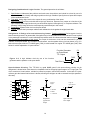
Labeling: The default name for all wires is “NET”, but since it is not a good idea to have them all labeled the same,
we will rename the ports so they are more meaningful. Rename the two inputs “A” and “B”, and call the
output, “A_AND_B”. To do this, you must first tell Mentor Graphics that you wish to be able to select
component properties. By default, you are not allowed to do so. Press the “Set Select Filter” button on the
schematic palette, and when the window appears, click the “Properties” box, then click “OK”. Next, select
one of the input port names, currently called “NET”, then right-click the mouse and choose “Change
Values:”. A dialog box will pop up at the bottom of the screen. Type the new net name in the “New Value”
text window then click “OK”. Do the same for the other two ports. Remember to have only one name
selected at a time and no components (including ports).
Documentation: We should give our schematic a title so everyone, including yourself, will know what it is we have
entered. For this example, it is quite obvious, but for a complex circuit it may not be immediately apparent
what the circuit represents. We should also add some information about who entered it, when it was entered
(or last modified), and perhaps for what purpose.
To add text such as this to the sheet, click the “Text” button on the main palette, select the “Add Comment”
option, and type your comment into the small text window that pops up. When you are done typing, place
the information in a convenient location on your sheet. Repeat this for each line of text you wish to add to
your sheet.
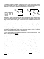
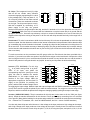
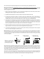
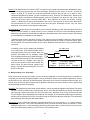
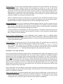
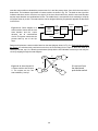
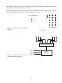
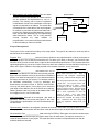
MY "AND" GATE
In addition to text, various shapes can be added
to your schematic. As a simple example, draw a
rectangular frame around your name, date, and
purpose. Accomplish this by selecting “Draw”
from the palette and choosing “Add Rectangle”.
Click and hold the left button of the mouse where
you want to start the rectangle, then drag the
mouse to the opposite corner and release the
button. When you have finished entering your
design, it should look something like the circuit
shown on the right.
74LS08
A_AND_
Author:
Date:
Purpose:
Christopher Maynard
October 18, 1996
ELE 202 Lab 5 - Example 1
III. Manipulating Your Schematic
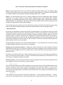
Once you are done entering your design, you can do several things with it. One obvious thing is to simulate it to
verify that you connected everything together correctly. Simulation is done using a different application, namely
the QuickSim II tool, which will be described later. Before we move onto the simulation aspect though, let's
discuss some of the less-obvious things that DA provides, and which you need to know in order to get through
the whole design process successfully.
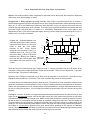
Checking: The design has to pass certain checks before it can be successfully registered (and saved). Do this by
using the “Check” pulldown menu, and selecting “sheet”. Once DA has checked your design, a window will
pop up giving a report of the check. All “errors” must be fixed. “Warnings” may or may not need to be fixed
for your design to work, depending on the warning. For example, an unconnected output triggers a warning,
but this may be perfectly fine for your circuit (like having an unused Q output from a flip-flop). You should look
at the warnings and make your own determination.
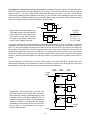
Registration: Once you have the schematic entered and checked, you must “register” it, i.e., make it known to
the rest of the world. This is done automatically when you save the sheet, which you should do often
DURING design entry, in case something goes wrong (the system dies), so that you don't lose all of your
work. Save the sheet by selecting: “Save” from the “File” pulldown menu.
21