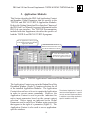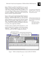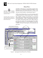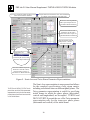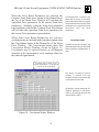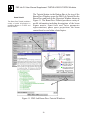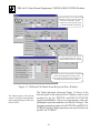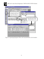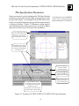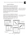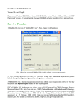
1
PBO Lab 2.0 User Manual Supplement: TURTLE & DECAY-TURTLE Modules ™ PBO Lab 2.0 (Particle Beam Optics Laboratory) User Manual Supplement: TURTLE & DECAY-TURTLE Application Modules Distributed by AccelSoft, Inc. P. O. Box 2813 Del Mar, CA 92014 USA (858) 677-0133 [email protected] www.ghga.com/accelsoft i PBO Lab 2.0 User Manual Supplement: TURTLE & DECAY-TURTLE Modules PBO Lab 2.0 User Manual Supplement: TURTLE and DECAY-TURTLE Application Modules 2000 by G. H. Gillespie Associates, Inc. All Rights Reserved. ISBN 1-892267-05-5 All rights reserved. No part of this book may be reproduced, in any form or by any means, without permission from the publisher. Printed in the United States of America. Published by AccelSoft Inc., San Diego, California. ii PBO Lab 2.0 User Manual Supplement: TURTLE & DECAY-TURTLE Modules “TURTLE User Manual” as used in this PBO Lab 2.0 User Manual Supplement refers to: TURTLE with MAD Input (Trace Unlimited Rays Through Lumped Elements), A Computer Program for Simulating Charged Particle Beam Transport Systems, and DECAY TURTLE, Including Decay Calculations, by D. C. Carey, K. L. Brown, and Ch. Iselin, September 1999. Fermi National Accelerator Laboratory report number Fermilab-Pbu-99/232. Stanford Linear Accelerator Center report number SLAC-R-544. Reproduced for distribution with PBO Lab by permission. DISCLAIMER NOTICE (TURTLE - Fermi National Accelerator Laboratory): This material was prepared as part of work sponsored by the United States Department of Energy. The Department of Energy, Universities Research Association, Inc., and their agents and employees, make no warranty, express or implied, and assume no legal liability or responsibility for the accuracy, completeness, or usefulness of any information, apparatus, product, or process disclosed, nor represent that its use would not infringe privately owned rights. TURTLE (Trace Unlimited Rays Through Lumped Elements) is a FORTRAN program maintained and distributed by the Fermi National Accelerator Laboratory. DECAY-TURTLE is also a FORTRAN maintained and distributed by the Fermi National Accelerator Laboratory. Both TURTLE and DECAYTURTLE are distributed with the PBO Lab software with the written permission of Fermi National Accelerator Laboratory. Running either the TURTLE or DECAY-TURTLE programs is accomplished directly from the PBO Lab interface - each code is fully integrated with the graphic user interface. The PBO Lab 2.0 (Particle Beam Optics Laboratory) User Manual describes the PBO Lab user interface. Two separate PBO Lab Application Modules are available for TURTLE and DECAY-TURTLE, repectively. This Supplement discusses the PBO Lab commands and options for both the TURTLE and DECAY-TURTLE Application Modules. Refer to the “TURTLE User Manual” distributed with this supplement for a description of the TURTLE program. iii PBO Lab 2.0 User Manual Supplement: TURTLE & DECAY-TURTLE Modules This page is intentionally blank. iv PBO Lab 2.0 User Manual Supplement: TURTLE & DECAY-TURTLE Modules Table of Contents Chapter and Subject Page 1. Getting Started . . . . . . . . . . . . . . . . . . . . . . . . . . . . . . . . . . . . . . . . . . . . . . . . . . . . . TURTLE . . . . . . . . . . . . . . . . . . . . . . . . . . . . . . . . . . . . . . . . . . . . . . . . . . . . . . . DECAY-TURTLE. . . . . . . . . . . . . . . . . . . . . . . . . . . . . . . . . . . . . . . . . . . . . . . . Running TURTLE . . . . . . . . . . . . . . . . . . . . . . . . . . . . . . . . . . . . . . . . . . . . . . . Running DECAY-TURTLE . . . . . . . . . . . . . . . . . . . . . . . . . . . . . . . . . . . . . . . . 1 3 4 5 7 2. Application Modules . . . . . . . . . . . . . . . . . . . . . . . . . . . . . . . . . . . . . . . . . . . . . . . . 9 Beam Line Global Parameters . . . . . . . . . . . . . . . . . . . . . . . . . . . . . . . . . . . . . 12 3. Beam Line Elements . . . . . . . . . . . . . . . . . . . . . . . . . . . . . . . . . . . . . . . . . . . . . . . Beam Piece . . . . . . . . . . . . . . . . . . . . . . . . . . . . . . . . . . . . . . . . . . . . . . . . . . . . Special Piece . . . . . . . . . . . . . . . . . . . . . . . . . . . . . . . . . . . . . . . . . . . . . . . . . . Quadrupole Apertures . . . . . . . . . . . . . . . . . . . . . . . . . . . . . . . . . . . . . . . . . Particle Names and Charge Parameters. . . . . . . . . . . . . . . . . . . . . . . . . . . . Additional Special Parameters . . . . . . . . . . . . . . . . . . . . . . . . . . . . . . . . . . Special Parameter Settings Window . . . . . . . . . . . . . . . . . . . . . . . . . . . . . . Marker Piece. . . . . . . . . . . . . . . . . . . . . . . . . . . . . . . . . . . . . . . . . . . . . . . . . . . Aperture Piece . . . . . . . . . . . . . . . . . . . . . . . . . . . . . . . . . . . . . . . . . . . . . . . . . Pipe Apertures . . . . . . . . . . . . . . . . . . . . . . . . . . . . . . . . . . . . . . . . . . . . . . . 15 18 23 25 26 28 30 32 35 40 4. TURTLE I/O Files . . . . . . . . . . . . . . . . . . . . . . . . . . . . . . . . . . . . . . . . . . . . . . . . . 41 5. Menu Commands. . . . . . . . . . . . . . . . . . . . . . . . . . . . . . . . . . . . . . . . . . . . . . . . . . 45 Commands Menu . . . . . . . . . . . . . . . . . . . . . . . . . . . . . . . . . . . . . . . . . . . . . . . 47 View Menu . . . . . . . . . . . . . . . . . . . . . . . . . . . . . . . . . . . . . . . . . . . . . . . . . . . . 49 6. Plot Specifications . . . . . . . . . . . . . . . . . . . . . . . . . . . . . . . . . . . . . . . . . . . . . . . . . Named Particles in DECAY-TURTLE . . . . . . . . . . . . . . . . . . . . . . . . . . . . . . . Plot Specification Parameters . . . . . . . . . . . . . . . . . . . . . . . . . . . . . . . . . . . . . . Plot List Window . . . . . . . . . . . . . . . . . . . . . . . . . . . . . . . . . . . . . . . . . . . . . . . Graph Plot Windows . . . . . . . . . . . . . . . . . . . . . . . . . . . . . . . . . . . . . . . . . . . . v 51 56 57 62 63 PBO Lab 2.0 User Manual Supplement: TURTLE & DECAY-TURTLE Modules Chapter and Subject Page 7. Options . . . . . . . . . . . . . . . . . . . . . . . . . . . . . . . . . . . . . . . . . . . . . . . . . . . . . . . . 65 Calculation Order . . . . . . . . . . . . . . . . . . . . . . . . . . . . . . . . . . . . . . . . . . . . 67 Observe Apertures Option . . . . . . . . . . . . . . . . . . . . . . . . . . . . . . . . . . . . . . 68 8. DECAY-TURTLE Example (“Example B - Pion Decay.pbol)” . . . . . . . . . . . . . . 71 9. Appendix: “TURTLE User Manual” . . . . . . . . . . . . . . . . . . . . . . . . . . . . . . . . . . . 83 TURTLE with MAD Input (Trace Unlimited Rays Through Lumped Elements), A Computer Program for Simulating Charged Particle Beam Transport Systems, and DECAY TURTLE, Including Decay Calculations vi PBO Lab 2.0 TM TM Getting Started User Manual Supplement: TURTLE & DECAY-TURTLE Application Modules 1 PBO Lab 2.0 User Manual Supplement: TURTLE & DECAY-TURTLE Modules 1. Getting Started This Getting Started Section is intended as a quick start introduction for running the TURTLE and DECAY-TURTLE Application Modules. The remainder of this Supplement describes the PBO Lab user interface features that are specific to these two Application Modules. Refer to the PBO Lab User Manual for more general information on the PBO Lab user interface. The TURTLE Documentation: “TURTLE with MAD Input (Trace Unlimited Rays Through Lumped Elements) A Computer Program for Simulating Charged Particle Beam Transport Systems and DECAY TURTLE Including Decay Calculations, describes the TURTLE and DECAY-TURTLE programs and is included with this Supplement. TURTLE TURTLE is a multi-particle ray tracing program used to transport particles through a charged particle optical system. TURTLE is an acronym for Trace Unlimited Rays Through Lumped Elements. The TURTLE program is useful to support the analysis of beamlines designed for TRANSPORT or for other PBO Lab Modules and can be used to model misalignments, apertures, slits, beam distortion and particle loss. TURTLE is often used to evaluate the effect of aberrations which exist in beams with small phase space volume, including higher order chromatic aberrations, effects of non-linearities in magnetic fields, and higher order geometric aberrations due to the accumulation of second-order effects. The lumped element approximation implemented by TURTLE precludes conventional local geometric aberrations due to large phase space. Refer to the TURTLE Documentation included with this Supplement for a complete discussion of the uses and limitations of the TURTLE program. 3 The TURTLE program can be used to evaluate the effects of aberrations in beams with small phase space volume, including chromatic aberrations, effects of non-linearities in magnetic fields and geometric aberrations due to accumulation of second-order effects. A TURTLE (or DECAY-TURTLE) option will be added to the Application Context pop up in PBO Lab Document Windows when the Application Module is installed. PBO Lab 2.0 User Manual Supplement: TURTLE & DECAY-TURTLE Modules When the TURTLE Application Module is installed in PBO Lab, a TURTLE option will be added to the Application Context pop up in PBO Lab Document Windows. The Application Context is used to indicate native inputs and in some cases, access applicationspecific user interface windows. TURTLE sub menus will also be placed in the View and Commands Menus. DECAY-TURTLE DECAY-TURTLE includes the ability to track both the original (Parent) particles and two decay products (Daughters) for radioactive beams. DECAY-TURTLE is a FORTRAN code for simulating the propagation of charged particles through an accelerator beamline or magnetic transport system. It is similar to the TURTLE program in many respects, but includes the additional ability to track both the original (Parent) particles and two decay products (Daughters) for radioactive beams. When the DECAY-TURTLE Application Module is installed in PBO Lab, a DECAY-TURTLE option will be added to the Application Context pop up in PBO Lab Document Windows. DECAY-TURTLE sub menus will also be placed in the View and Commands Menus of the PBO Lab Document Windows. Professional Versions of both TURTLE and DECAY-TURTLE for PBO Lab are available from AccelSoft. Professional Versions of both TURTLE and DECAYTURTLE Application Modules for PBO Lab are available for users who have custom or unique requirements. Contact AccelSoft for further information. This PBO Lab Supplement for the TURTLE Application Module describes the PBO Lab user interface features that are specific to the TURTLE and DECAY-TURTLE Application Module. Unless otherwise stated, the features described for TURTLE are applicable to DECAY-TURTLE. However, specific sub sections are provided for features that are exclusive to the DECAY-TURTLE program. 4 PBO Lab 2.0 User Manual Supplement: TURTLE & DECAY-TURTLE Modules Running TURTLE TURTLE is executed from the TURTLE Commands menu, shown in Figure 1, by selecting either the Write Input and Run TURTLE or Run ‘Turtle Input’ File commands. Figure 1. TURTLE Commands Menu. The first command is the primary command for generating input and executing TURTLE. The three commands in the second group are used to generate native TURTLE input without automatically executing the program. The input file generated by PBO Lab can be edited directly and then the last command in this group can be used to execute TURTLE with the modified input. These commands are provided for users that are experienced with the native format and syntax supported by the TURTLE program. The TURTLE Commands menu is used to generate native TURTLE input and execute the TURTLE program. Commands are also provided for Options and Plot Specifications. The first TURTLE command is used to generate native input and execute TURTLE. The second group of commands is used to generate the native input file for TURTLE without automatically executing the program. The last two items in the TURTLE Commands menu are used to access TURTLE Options and Plot Specifications. These are each described in separate Chapters in this Supplement. Running the TURTLE Module is straightforward. Simply select Write Input and Run TURTLE from the Commands Menu as illustrated in Figure 2. The command is executed after the mouse button is released, causing PBO Lab to write the TurtleInput file for the current beamline model as defined in the model space of the Document Window and run the TURTLE Application Module. Upon completion, the TurtleOutput file will be displayed in a PBO Lab Text Edit Window, as illustrated in Figure 2. 5 Run the TURTLE program by simply selecting the Write Input and Run TURTLE command from the Commands Menu. PBO Lab 2.0 User Manual Supplement: TURTLE & DECAY-TURTLE Modules The first TURTLE Command Prepares a Turtle Input file for the Beamline in the Model Space and then Executes the TURTLE Program Turtle I/O files are overwritten on each execution of the Write Input and Run Turtle or the Write Input and View Commands. Figure 2 is an example of the TurtleOutput file displayed when execution is complete. The content of the native TurtleOutput file will depend on various Plot Specifications and Options set by the user. HISTOGRAM NO 1 HORIZONTAL AXIS X IN M VERTICAL AXIS X' IN R -.010 -.006 -.014 -.013 -.012 -.011 -.010 -.009 -.008 -.007 -.006 -.005 -.004 -.003 -.002 -.001 .000 .001 .002 .003 .004 .005 .006 .007 .008 .009 .010 .011 .012 .013 TO TO TO TO TO TO TO TO TO TO TO TO TO TO TO TO TO TO TO TO TO TO TO TO TO TO TO TO -.013 -.012 -.011 -.010 -.009 -.008 -.007 -.006 -.005 -.004 -.003 -.002 -.001 .000 .001 .002 .003 .004 .005 .006 .007 .008 .009 .010 .011 .012 .013 .014 TOTALS TOTAL NUMBER OF ABOVE BELOW .959 M .959 M -.002 FROM THE START FROM THE START .002 .006 .010 TOTALS I**---**---**---**---**---**---**---**---**---**---**I------I I 0 I I 0 I I 0 I 11 12 11 I 7 I 1 41 132 1121 1 I 18 I 213 12 1111 11 I 15 I 123515 3123 4 1 1 I 32 I 15 2246438 41132 I 46 I 11 2 141 3322634222 2 I 41 I 1321648332339327214 1 I 68 I 112323434466124221323 I 59 I 2122253354353384551311 I 71 I 213446154413723342 1 I 60 I 2 1254452551A32412212 I 63 I 132 41242289233515 53 2 I 67 I 1 1121475444227454224212 I 71 I 1134 64764225313443311 1 I 69 I 1 33 75341583162 12311 2 I 62 I 2221433521542543145123 1 I 65 I 2252 2356454631 2 1 I 53 I 23 231264 223443311 I 46 I 12112 2121328 1131 I 32 I 21113613 14323 1 I 32 I 2112 21121 I 13 I 1 1 4 1 I 7 I 1 1 1 I 3 I I 0 I I 0 I**---**---**---**---**---**---**---**---**---**---**I------I I I I I I I 112255754775657543421 I I 00000000000015474974236763892218408640000000000000 I 1000 ENTRIES = 1000 INCLUDING UNDERFLOW AND OVERFLOW AS FOLLOWS LEFT RIGHT 0 0 0 0 1000 0 0 0 0 SUM OF SQUARES = 3910. CENTER = .000 RMS HALF WIDTH = CENTER = .000 RMS HALF WIDTH = CORRELATION = .0103 .002 .005 Figure 2. Executing the TURTLE Application Module. The native TurtleOutput file is automatically displayed in a scrollable Text Edit Window following the execution of TURTLE. The content of the Output file will depend on the Plot Specifications and Options set by the user. Use the Save As command in the File Menu of the Text Edit Window to rename the output file if desired. The TurtleInput file, TurtleOutput file and Turtle PlotData file will be overwritten on any subsequent execution of the TURTLE Application Module. 6 PBO Lab 2.0 User Manual Supplement: TURTLE & DECAY-TURTLE Modules Running DECAY-TURTLE Running DECAY-TURTLE is the same as described for the TURTLE Application Module. However, DECAYTURTLE is executed from the DECAY-TURTLE Commands menu, shown in Figure 3. Chapter 8 in this Supplement provides a tutorial example of using DECAY-TURTLE. The DECAY-TURTLE Commands Menu is used to Execute DECAY-TURTLE The Parent Particle Lifetime and the Decay product Masses for DECAY-TURTLE are accessed in the Tracing/Tracking Global Parameters tab panel The names and charges of the primary (Parent) particle and the decay products are set using the PBO Lab Special (SPEC) Piece Figure 3. DECAY-TURTLE Commands Menu. DECAY-TURTLE requires some additional Global Parameters to be specified for the Parent Particle Lifetime and the Decay Particle Masses which are set in the Tracing/ Tracking panel of the Global Parameters. The names and charges of the primary (Parent) particle and the (secondary) decay particles are set using the PBO Lab Special (SPEC) Piece. Refer to the Beamline Global Parameters Section for a description of the Global Parameters used by DECAYTURTLE. The Special Piece Section describes naming particles and specifying the charge parameters for decay particles the charge parameters for decay particles. 7 Decay product masses are set in the Tracing/Tracking panel of the Global Parameters. The charges of the decay particles are set using the PBO Lab SPEC Piece. PBO Lab 2.0 User Manual Supplement: TURTLE & DECAY-TURTLE Modules PBO Lab also provides graphic representations of the data generated by TURTLE and DECAY-TURTLE. Any plot specifications will result in PBO Lab Graph Plot Windows opening automatically after execution. PBO Lab provides interactive Graph Plot Windows that replace the native character based plots generated by the TURTLE and DECAY TURTLE programs. Examples of the PBO Lab Scatter Plots are shown in Figure 4. Plot Specifications can be created for any location in the beamline by placing a Marker Piece in the beamline model and accessing the Plot Specification Window with the Open Button in the Diagnostics panel. The Plot List command in the Commands Menu (TURTLE and DECAY-TURTLE) can be used to list and access all of the Plot Specifications for the entire beamline. Refer to the Marker Piece Section in the Beamline Elements Chapter, as well as the Plot Specifications Chapter in this Supplement. PBO Lab interactive Graph Plot Windows, such as those illustrated in Figure 4 below, are automatically created for the data generated by TURTLE and DECAY-TURTLE. Figure 4. PBO Lab Graph Plot Windows for TURTLE. 8 PBO Lab 2.0 TM TM Application Modules User Manual Supplement: TURTLE & DECAY-TURTLE Application Modules 9 PBO Lab 2.0 User Manual Supplement: TURTLE & DECAY-TURTLE Modules 2. Application Modules This Section describes the PBO Lab Application Context and beamline Global Parameters that are specific to the TURTLE and DECAY-TURTLE Application Modules. Refer to the Getting Started and User Interface Chapters of the PBO Lab User Manual for general information on the PBO Lab user interface. The TURTLE Documentation, included with this Supplement, describes the specifics of both the TURTLE and DECAY-TURTLE programs. Set the Application Context pop-up for the TURTLE or DECAY-TURTLE Application Module Tab Panels Provide Access to Additional Global Parameters used by TURTLE and DECAY-TURTLE Green Dots Indicate which Parameters are Native Inputs for the Current Application Context Figure 5 TURTLE Application Context and Global Parameters. The Application Context pop up in the Button Bar of the Document Window (Figure 5) contains selections for all of the installed Application Modules. The Application Context does not have to be set to a particular Application in order to execute menu commands. However, the Application Context is used to provide indicators for native input parameters based on the current context selection. Native inputs are indicated in the Global Parameters and in each Piece Window using green dots that appear to the right of a parameter (Figure 5). The Application Context is also used to access applicationspecific windows. 11 The selected Application Context is used to activate application - specific controls and user interface windows, in addition to providing applicationspecific feedback to the user. PBO Lab 2.0 User Manual Supplement: TURTLE & DECAY-TURTLE Modules Beamline Global Parameters PBO Lab Global Parameters are global to the entire beamline model and include inputs for: Particle Charge, Particle Mass, Beam Energy and Frequency. The PBO Lab Beam Line Global Parameters are described in the Getting Started and User Interface Chapters of the PBO Lab User Manual. This Section discusses the Global Parameters that are used by the TURTLE and DECAYTURTLE Application Modules. The native Global Parameters for TURTLE and DECAYTURTLE include the Particle Charge, Particle Mass, Beam Energy and Frequency. These parameters are indicated with green dots, as illustrated in Figure 6, when the Application Context is set for TURTLE or DECAYTURTLE in the Document Window. Hide and Show the Global Parameters from the View Menu or the Button Bar The Beamline Global Parameters are accessed from three tab panels that float over the Work Space of the Document Window Green Dots next to Global Parameters indicate the Native Inputs for the Current Application Context Global Parameters have built-in Default Values Guidance Limits Alert User if Parameters Are Outside Reasonable Bounds Different Units Options Are Available for Most Parameters Figure 6. Beamline Global Parameters in the Document Window. 12 PBO Lab 2.0 User Manual Supplement: TURTLE & DECAY-TURTLE Modules Both TURTLE and DECAY-TURTLE also use the Number of Macro Particles Global Parameter, which is found on the Tracing/Tracking Global tab panel. Click on the Tracing/Tracking tab in the Document Window to access the Number of Macro Particles Global Parameter, as well as, additional Global Parameters used by the DECAY-TURTLE Application Module. Figure 7 shows the Tracing/Tracking Global Parameters tab panel. In addition to the Number of Macro Particles Parameter, DECAY-TURTLE also uses the last three Global Parameters in this tab panel: Particle Lifetime (Parent), Decay Particle 1 Mass and Decay Particle 2 Mass. The remaining Global Parameters are used for a variety of PBO Lab calculations and displays or they may be used by other Application Modules. The Number of Macro Particles Global Parameter used by TURTLE and DECAY-TURTLE is found on the Tracing/Tracking tab panel. Additional Global Parameters found on the Tracing/Tracking tab panel are used exclusively by the DECAYTURTLE Module: Particle Lifetime (Parent), Decay Particle 1 Mass and Decay Particle 2 Mass Included with the beamline Global Parameters is a tab panel for Initial Floor Coordinates of the beam reference trajectory. These parameters are not used by the TURTLE or DECAY-TURTLE Application Modules. The Application Context is set in the Button Bar of the Document Window Additional Beamline Global Parameters for TURTLE and DECAY-TURTLE are accessed from the Tracing & Tracking tab panel in the Document Window Green Dots next to Global Parameters indicate the Native Inputs for the Current Application Context Figure 7. PBO Lab Global Parameters Used for DECAY-TURTLE. 13 PBO Lab 2.0 User Manual Supplement: TURTLE & DECAY-TURTLE Modules The Particle Charge, Particle Mass, Beam Energy and Frequency are in the Globals tab panel in the Document Window. The Particle Charge, Particle Mass, Beam Energy and Frequency are among the first five Global Parameters and are readily accessible in the Global Parameters Pane on the Work Space of the Document window. These Parameters are used to generate native inputs, such as the mass of particles in the beam, the reference trajectory momentum and the reference momentum for magnetic fields, for both TURTLE and DECAY-TURTLE. The Tracing/Tracking Global Parameters tab panel is used to access the Number of Macro Particles Parameter and the Particle Lifetime (Parent), Decay Particle 1 Mass and Decay Particle 2 Mass used by DECAY-TURTLE. The Number of Macro Particles Global Parameter is used to specify the number of rays that will be traced through the beamline. The Decay product Masses are set in the Tracing/Tracking panel of the Global Parameters. However, the Charges for decay particles are set using the PBO Lab Special (SPEC) Piece. The Number of Macro Particles Global Parameter is used to specify the number of rays that will be traced through the beamline. It is set to one thousand (1000) as a default value but has a practical range from one to ten thousand, which is reflected by the Limits displayed in the Global Parameters Pane. These are “soft” limits which do NOT restrict the user’s input in any way. They are simply indicators of a reasonable range for a parameter based on a variety of factors such as other Global Parameters. The maximum number of rays (Macro Particles) is dependent on other storage requirements, such as the number of elements in the beamline model. Computation time is also a factor for tracing a very large number of macro particles. The lifetime for the parent particle used by DECAYTURTLE and the decay product Masses are also set in the Tracing/Tracking panel of the Global Parameters. However, the Charges for decay particles are set using the PBO Lab Special (SPEC) Piece. The use of the Special Piece is described in the Special Piece Section of the Beamline Elements Chapter. 14 PBO Lab 2.0 TM TM Beamline Elements User Manual Supplement: TURTLE & DECAY-TURTLE Application Modules 15 PBO Lab 2.0 User Manual Supplement: TURTLE & DECAY-TURTLE Modules 3. Beamline Elements The PBO Lab Pieces implemented for the TURTLE and DECAY-TURTLE Application Modules are listed in Table 1 below. Native inputs for these elements are indicated with green dots in the Piece Windows when the Application Context is set to TURTLE or DECAYTURTLE in the Document Window. Green dots are displayed to the right of individual Piece Parameters that are used to generate the native input files for TURTLE and DECAY-TURTLE. Table 1. PBO Lab Pieces supported by TURTLE and DECAY-TURTLE. Beam Bend Accelerator Not all of the beamline elements implemented in PBO Lab are supported by all Application Modules. Table 1 lists all of the Pieces that are recognized by TURTLE and DECAYTURTLE. Pieces in the beamline model that are not supported will be treated as zero-length drifts when generating native input for TURTLE and DECAYTURTLE. The Beam Piece is used to specify initial particle distributions. Eta The Marker Piece is used for setting Plot Specifications. Drift Edge Align Param Quadrupole Lens Kicker Aperture Solenoid Plasma Lens ∆RMS Special RF Gap Sextupole Rotate Marker (Final) Sector Bend Octupole Septum Final Rectangular Bend Centroid Matrix The Piece Window user interface is described in the Getting Started and User Interface Chapters of the PBO Lab User Manual. However, the Beam Piece, Marker Piece and Special Piece have features specific to TURTLE and DECAY-TURTLE which are described in this Chapter. The Aperture Piece is used exclusively by the TURTLE and DECAY-TURTLE Application Modules and is also described in this Chapter. 17 The Aperture Piece is used exclusively by TURTLE and DECAY-TURTLE. The Special Piece is used to specify particle charges for DECAY-TURTLE. PBO Lab 2.0 User Manual Supplement: TURTLE & DECAY-TURTLE Modules Beam Piece The beamline model must include a Beam Piece in order to generate the native beam inputs for TURTLE and DECAY-TURTLE. The Green dots to the right of individual parameters indicate which will be used to generate TURTLE and DECAY-TURTLE inputs. The PBO Lab Beam Piece is used to define an initial particle distribution for TURTLE and DECAY-TURTLE. The beamline model must include a Beam Piece, usually as the first piece in the beamline, as illustrated in Figure 8. Double-click the Beam Piece Icon in the beamline model to open the Beam Piece Window shown below. The Beam Piece Window contains two tab panels: one for Beam Element Parameters and the other for Beam Centroid and Current Parameters. There is a Button Bar at the top of the window and dynamic phase space ellipse plots are provided to the right of the parameter tab panels. When the Application Context is set for TURTLE or DECAYTURTLE, the native beam inputs will be indicated with green dots. Set the Application Context for TURTLE (or DECAY-TURTLE) Double-Click the Beam Piece Icon in the Beamline to Open the Beam Piece Window Figure 8. Opening the Initial Beam Piece Window. 18 PBO Lab 2.0 User Manual Supplement: TURTLE & DECAY-TURTLE Modules The Beam Piece Window has two tab panels for parameter inputs: Beam Element Parameters and Centroid Parameters. The parameters on the Centroid tab panel are not used by TURTLE or by DECAY-TURTLE. However, PBO Lab does provide a Centroid beamline element that is supported by TURTLE. The Beam Piece Window includes dynamic phase space ellipse plots for the initial beam parameters. The top plot shows the horizontal (red) and vertical (blue) transverse phase space ellipses. The bottom plot shows the longitudinal phase space ellipse (green). The axis scales for the phase space ellipse plots can be calculated automatically with the Auto Scale Plots button in the Button Bar at the top of the window or the scales may be set directly by the user with the Set Plot Scale button. Changes made to any Beam Parameters or changing between the two parameter representations, results in an update of the phase space ellipse displays. The Particle Distribution Type pop up at the top of the Beam Elements tab panel is used to specify the type of particle distribution that will be generated using the users specified beam parameters. This pop up is illustrated in Figure 6 and contains selections for 6-D Equivalent Uniform, 4-D Equivalent Uniform (KV), Gaussian (5Sigma) and Rectangular distribution types. The phase space ellipse plots in the Beam Window do not reflect the distribution selection. To display the initial particle distribution, place a Marker Piece after the Beam Piece in the beamline model and use it to specify a 2-D Correlation Plot for that location in the beamline. (See Marker Piece Section in this Chapter.) The Beam Piece can be used to specify the initial distribution in two different ways, referred to as the SemiAxes representation and the Twiss parameter, or CourantSnyder representation. Both the Semi-Axes and Twiss parameters are shown in Figure 9. The Beam Parameters pop up near the top of the window (Figure 8) is used to toggle between these two parameter representations. 19 Parameter Tab Panels The parameters on the Centroid tab panel of the Beam Piece are not used by TURTLE or by DECAY-TURTLE. Phase Space Plots The Beam Piece Windows include phase space ellipse plots for the current Beam Parameters. Particle Distribution Type TURTLE generates an initial particle distribution based on the specified Beam Parameters and the Particle Distribution Type pop up. The Number of Macro Particles Global Parameter is used to specify the number of particles. Beam Parameter Representations The native beam inputs for TURTLE can be generated from either the Semi-Axes or Twiss Beam Piece parameters. PBO Lab 2.0 User Manual Supplement: TURTLE & DECAY-TURTLE Modules Open the Correlations Matrix Window with Semi-Axes Parameters Selected Compute Semi-Axes Parameters from Twiss Parameters or Compute Twiss Parameters from Semi-Axes Transverse and Longitudinal Phase Space Ellipse Plots are Provided for Beam Parameters Green Dots Indicate which Parameters will be used to Generate the Native Inputs for TURTLE and DECAY-TURTLE Auto-Scale Phase Space Ellipse Plots or Set the Plot Scales Directly Select between Semi-Axes or Courant-Snyder (Twiss) Beam Parameter Representations The Tutorial Button Opens the Beam Piece Tutorial window, which Provides a Variety of Information on Beam Parameters Figure 9. Semi-Axes and Twiss Beam Parameter Representations. TURTLE and DECAY-TURTLE both permit the use of the Twiss parameter representation only for the transverse phase planes (horizontal and vertical) of the initial beam. The Semi-Axes representation is more general and allows for the complete specification of any sigma matrix, including correlations between different phase planes. The Twiss parameter representation is useful for specifying initial beams in which the phase planes (horizontal, vertical and longitudinal) are decoupled. TURTLE and DECAY-TURTLE permit the use of the Twiss parameter representation only for the transverse phase planes (horizontal and vertical) of the initial beam. 20 PBO Lab 2.0 User Manual Supplement: TURTLE & DECAY-TURTLE Modules When the Twiss Beam Parameters are selected, the Compute From Semi-Axes button in the Button Bar at the top of the Beam Piece Window will calculate the equivalent Twiss parameters for the current Semi-Axes parameters. Similarly, when the Semi-Axes parameter representation is selected the Compute From Twiss button will calculate the equivalent Semi-Axes parameters for the current Twiss parameter representation. When Semi-Axes Beam Parameters are selected, correlations may be included in the beam description using the Correlations button in the Button Bar of the Beam Piece Window. The Correlations button opens the Correlation Matrix Window shown in Figure 10. Correlations may be entered directly as off-diagonal elements of the sigma-matrix, or by entering values for the reduced sigma matrix. The Compute From... button is in the Button Bar at the top of the Beam Piece window and is used to compute Twiss parameters from the Semi-Axes parameters or to compute Semi-Axes parameters from the Twiss parameters. Correlation Matrix Correlations may be included in the beam description when the Semi-Axes Beam Parameters representation is used. Correlations may be entered for the Reduced Sigma Matrix or as off-diagonal elements of the Sigma Matrix The Beam Correlations Matrix window is opened with the Correlations button in the Button Bar of the Beam Piece window. Correlations may be entered as offdiagonal elements of the sigmamatrix, or by entering values for the reduced sigma matrix. Figure 10. Correlation Matrix Window. 21 PBO Lab 2.0 User Manual Supplement: TURTLE & DECAY-TURTLE Modules Beam Tutorial The Beam Piece Tutorial provides a variety of useful information on modeling Beams in TURTLE and DECAY-TURTLE. The Tutorial button in the Button Bar at the top of the Beam Piece Window opens the PBO Lab Tutorial for the Beam Piece and leads to the Hypertext Window shown in Figure 11. The Beam Piece Tutorial provides a variety of useful information including descriptions of the beam Sigma matrix, Semi-Axes and Twiss parameter representations, phase space projections, the beam centroid and several other related topics. Figure 11. PBO Lab Beam Piece Tutorial Windows. 22 PBO Lab 2.0 User Manual Supplement: TURTLE & DECAY-TURTLE Modules Special Piece The Special Piece is used to define special parameters at specific locations in the model. The Special Piece may be inserted at any location in the beamline for application to subsequent calculations. In many cases the Special Piece is used to specify parameters for the entire beamline model, in which case the Special Piece should be placed at the beginning of the beamline, following Initial Beam Piece. Special (SPEC) Piece The Special Piece Window, illustrated in Figure 13, has five tab panels for the different types of special parameters. Each of these tab panels is described separately in this Section starting with the last tab panel, which has parameters that are specific to both TURTLE and DECAYTURTLE. Both TURTLE and DECAY-TURTLE use the Quadrupole Aperture Parameters on the Turtle tab panel in the Special Piece Window. In addition, the Charge Parameters on the Turtle tab panel are used to define symbolic names for the primary and secondary particles for DECAYTURTLE and specify charges for these particles. Although the Special Piece is generally used for locationspecific parameters settings, the Particle Names and Charges apply to the entire beamline model, regardless of the location of the Special Piece in the beamline. Only one Special Piece should be used to specify particle names and charges. However, multiple Special Pieces may be used to define different Quadrupole Aperture parameters or other Special Parameters at various locations in the beamline model. The remaining tab panels in the Special Piece Window are for changing System Parameters, Fringe Field Parameters and Expansion Parameters at specific locations in the model. The Floor Coordinate Parameters on the Floor tab panel are exclusive to the TRANSPORT Application Module and are not used by TURTLE or DECAY-TURTLE. 23 Quadrupole Aperture Para-meters are used by both TURTLE and DECAYTURTLE. The Charge Parameters are used to define symbolic names and charges for the Primary and Secondary Particles in DECAYTURTLE. Only one Special Piece should be used for specifying particle names and charges for the entire beamline. PBO Lab 2.0 User Manual Supplement: TURTLE & DECAY-TURTLE Modules The Special Piece can be used for the definition of location specific Special Parameters that modify System , Fringe Field and Expansion inputs for TURTLE and DECAY-TURTLE The Floor Tab Panel contains Floor Coordinate Parameters that are not used by TURTLE or DECAY-TURTLE The Turtle Tab Panel in the Special Piece Window is used to define Quadrupole Apertures and to specify Names and Charges for the Primary and Secondary Particles in DECAY-TURTLE Figure 13. Different Tab Panels from the Special Piece Window. The Turtle tab panel is the last tab panel in the Special Piece Window and is used exclusively by TURTLE and DECAY-TURTLE. The Turtle tab panel (shown in Figure 13 above) is the last tab panel in the Special Piece Window and is used exclusively by the TURTLE and DECAY-TURTLE Application Modules There are six parameters, three for Quadrupole Apertures and three for Particle Charges. The Aperture parameters apply to both TURTLE and DECAYTURTLE, but the Charge parameters are used exclusively by DECAY-TURTLE. 24 PBO Lab 2.0 User Manual Supplement: TURTLE & DECAY-TURTLE Modules Quadrupole Apertures The first three parameters in the Turtle tab panel of the Special Piece Window are used to specify Quadrupole Apertures. All quadrupoles in the beamline model have circular apertures by default, with the radius taken from the individual Quadrupole Piece Windows. However, the quad Geometry tab panel in individual Quadrupole Piece Windows has a Pipe Aperture pop up that provides for Circular, Rectangular and Elliptical apertures to be specified. The individual quadrupole settings for Pipe Aperture and Radial Aperture parameters are overridden when the Quadrupole Piece is proceeded by a Special Piece with non-zero Quadrupole Aperture Parameters in the Turtle tab panel. Individual quadrupole apertures are also overridden by the Observe Apertures Option in the TURTLE Options Window (for TURTLE) or the DECAY-TURTLE Options Window (for DECAY-TURTLE). If the Observe Apertures Option is set to None, then the quadrupole aperture settings will not be observed and any apertures specified with Special Pieces will also be ignored. Note that the Observe Apertures Option does not apply to the Aperture Piece, (referred to as a Slit element in the TURTLE Documentation), but it does apply to any magnet element such as Quadrupoles, Bends, Sextupoles and Octupoles. The Quadrupole Aperture Parameters in the Special Piece Window apply only to Quadrupoles following the Special Piece in the beamline model, not to other magnet elements or to Quadrupoles that precede the Special Piece in the beamline model. 25 Individual quadrupole settings for Pipe Aperture and Radial Aperture parameters are overridden when a Quadrupole Piece is proceeded by a Special Piece with non-zero Quadrupole Aperture Parameters in the Turtle tab panel. If the Observe Apertures Option is set to None, then the quadrupole aperture settings will not be observed and any apertures specified with Special Pieces will also be ignored. The Observe Apertures Option does not apply to Aperture Pieces (Slit elements) in the beamline model. PBO Lab 2.0 User Manual Supplement: TURTLE & DECAY-TURTLE Modules Particle Names and Charge Parameters In order for DECAY-TURTLE to calculate the decay of a primary particle into secondary particles, the names and charges for the primary and secondary particles must be specified in the Turtle tab panel of the Special Piece Window. The Special Piece is used to specify the particle names and charges for the primary and secondary particles in DECAY-TURTLE. The primary and secondary particles must be named in order to specify the Charge Parameters in the Special Piece Window and to specify plots for the different particle types in the Plot Specification Window. On the left of each of the Charge Parameters in the Special Piece Window, there are Special Parameter Settings buttons (“S-buttons”) which provides access to Special Parameter Settings Windows that are used to name the particles. The last three parameters in the Turtle tab panel are used exclusively by DECAY-TURTLE to specify particle names and charges for primary and secondary particles. The Parent Charge parameter is followed by two secondary particle charge parameters referred to as first daughter (Daughter1) and second Daughter (Daughter2) particles. The default for the Parent particle and Daughter1 particle is for unit positive charge and neutral for Daughter2 particle. Only charges of +1, -1 or 0 have any meaning for DECAY-TURTLE. Charge conservation is not required. The primary and secondary particles must be named in order to specify the Charge Parameters in the Special Piece Window and to specify plots for the different particle types in the Plot Specification Window. On the left of the Charge Parameters, there are Special Parameter Settings buttons (“S-buttons”) which provide access to Special Parameter Settings Windows that are used to name the particles. Figure 14 on the following page illustrates opening the Special Parameter Settings Windows. The Charge parameters are specified in the Special Piece Window and the “S-Buttons” for each parameter are used to open the corresponding Special Parameter Settings Window for naming the particles. The charge parameters are only defined for named particles. In this example the parent particle has been given the Symbolic Parameter Name: “PION” with a charge of +1 and the decay particles are named “MUON” and “NEUTRINO” with charges of +1 and 0 respectively. When a name has been defined for a particle, the S-button will have a red “S”. 26 PBO Lab 2.0 User Manual Supplement: TURTLE & DECAY-TURTLE Modules Special Parameters must be defined by a Symbolic Parameter Name in the Special Parameter Settings Window that is accessed using the parameter's "S-Button" Figure 14. Specifying Particle Names and Charges for DECAY-TURTLE. The charge for the primary particle is specified in the Globals tab panel of the Beamline Global Parameters in the Document Window. Particle masses for the primary and secondary particles and the lifetime for the primary particle are specified in the Tracing/Tracking tab panel of the Beamline Global Parameters. Refer to the Beamline Global Parameters Section in this Supplement for a description of these parameters. 27 Parameters for the primary particle charge and lifetime, in addition to the secondary particle masses, are specified in Beamline Global Parameters in the Document Window. PBO Lab 2.0 User Manual Supplement: TURTLE & DECAY-TURTLE Modules Additional Special Parameters The Special Piece provides additional parameters for the definition of location specific inputs that can be used to change System parameters, Fringe Field parameters and Expansion parameters. Table 2 list the Special Parameters and the corresponding TURTLE and DECAY-TURTLE keywords. Special Pieces must precede any element(s) to which they apply. Once a Special Parameter has been defined for a location in the beamline model, it will apply to all succeeding elements that are the appropriate type unless reset to a new value. PBO Lab will only use Special Parameters that have been defined by a Symbolic Parameter Name in the parameters’ Special Parameter Settings Window. Note that the Fringe Field Factor K2 (FINT2) is no longer used, but is included for compatibility with older versions. Refer to the TURTLE Documentation for a description of individual special parameters. Special Pieces on Work Space are ignored when generating special instructions (SPEC cards). Table 2. Special Piece Parameters and Keywords. Special Piece Parameter System Parameters System Length Reference Trajectory Momentum Magnetic Field Reference Momentum Particle Mass Tilt to Focal Plane Fringe Field Parameters Horizontal Half-Width Half Pole Spacing Orbit Displacement Integral Fringe Field Factor K1 Fringe Field Factor K2 Entrance Pole-Face Curvature Exit Pole-Face Curvature Expansion Parameters Second-Order Field Third-Order Field Excess Field Fraction Field Scaling Factor Vertical Dipole Factor Vertical Gradient Factor Vertical Sextupole Factor Keyword LENGTH P0 PREF PMASS FOTILT HWIDTH HGAP FINT0 FINT FINT2 H1 H2 EPS EPS3 RMPS RNMS VR NP EPSP The Special Piece can be placed anywhere in the beamline by dragging the icon from the Palette Bar and inserting it at the desired location in the beamline model. Special Pieces on the Work Space are ignored when generating special instructions (SPEC cards). 28 PBO Lab 2.0 User Manual Supplement: TURTLE & DECAY-TURTLE Modules Special Pieces must precede any element(s) to which they apply. Once a Special Parameter has been defined with a symbolic name and value, it will apply to all succeeding elements of the appropriate type. (An exception is made for particle names and charges, which apply to the entire beamline model.) Deleting the symbolic name for a Special parameter will disable the parameter without deleting the value assigned to that parameter in the Special Piece Window. Moving a Special Piece from the Model Space to the Work Space will also disable any Special Parameters defined by that piece. Special Pieces effect all succeeding elements of the appropriate type. (An exception is made for particle names and charges, which apply to the entire beamline model. Moving a Special Piece from the Model Space to the Work Space will also disable any Special Parameters defined by that piece. Figure 15 shows an example of the Special Piece Window and Special Parameter Settings Window for the Reference Trajectory Momentum parameter. Note that there is no tab panel for TURTLE or for DECAY-TURTLE in the Special Parameter Settings Window for the Momentum parameter. However, a Symbolic Parameter Name must be specified in the Special Parameter Settings Window in order for the SPEC card to be included in the native TURTLE or DECAY-TURTLE input. Special Parameters must be defined by a Symbolic Parameter Name in the Special Parameter Settings Window that is accessed using the parameter's "S-Button" Figure 15. Defining a Symbolic Parameter Name. 29 PBO Lab 2.0 User Manual Supplement: TURTLE & DECAY-TURTLE Modules A single Special Piece may be used to define multiple Special Parameters for a specific location. Multiple Special Pieces can also be placed at different locations to redefine a single Special Parameter. However, PBO Lab will only use Special Parameters that have been defined by a Symbolic Parameter Name in the parameter’s Special Parameter Settings Window, as illustrated in Figures 15 and 16. Special Parameter Settings Window When an Application Module is installed, a corresponding tab panel will be included in the Special Parameter Settings Window if that parameter supports any special settings for that Application Module. Otherwise there will not be an application-specific tab panel in the S-Window for that Application. Many Piece Parameters support application-specific special parameter settings that are accessed with the Special Parameter Settings Buttons (“S-Buttons”) located next to each parameter in the PBO Lab Piece Windows. The S-Buttons open Special Parameter Settings Windows for the associated parameters. The Special Parameter Settings Windows (“S-Windows”) have a applicationindependent panel at the top of the window as illustrated in Figure 16. The bottom part of the window contains application-specific tab panels for any installed Application Modules that support special settings for the particular parameter. Special Parameter Settings for both TURTLE and DECAY-TURTLE are only found on the Special Piece. The Symbolic Parameter Name for a Piece Parameter is application- independent, i.e. the same Parameter Name is used for specifying Special Parameter Settings for all installed Application Modules The Piece Comment (Label) and the Piece Parameter name are displayed at the top of the S- Window The bottom portion of the Special Parameter Settings Window contains application-specific tab panels for the different Application Modules that support special parameter settings for a particular parameter Figure 16. Special Parameter Settings Window. 30 PBO Lab 2.0 User Manual Supplement: TURTLE & DECAY-TURTLE Modules Only Special Parameters that have been defined with a Symbolic Parameter Name in the parameters’ Special Parameter Settings Window are used to generate the native input for TURTLE or DECAY-TURTLE. If a Symbolic Parameter Name has not been assigned, then a SPEC card will not be generated. Special Parameters should be defined with unique Symbolic Parameter Names, particularly when the same Special Parameter is defined at different locations in the beamline model, otherwise the last non-unique Parameter Name and Value will be used for each Special Parameter defined by that Name. Parameter Names should not be the same as Piece Labels (Comment String in Piece Windows) or unintended consequences may result. Copying a Special Parameter Piece will also copy any Special Parameter Settings including Symbolic Parameter Names. When a Special Piece is copied, care should be taken to assign unique Symbolic Parameter Names. All of the Special Parameter Settings for a PBO Lab beamline model are saved from the Document Window with the Save or Save As commands in the File Menu. 31 PBO Lab will only use Special Parameters that have been defined by a Symbolic Parameter Name in the parameters’ Special Parameter Settings Window. Special Parameter Names should be unique with respect to other Parameter Names and Piece Labels. Copying Special Pieces will duplicate any Symbolic Parameter Names and may result in unintended consequences. All Special Parameter Settings are saved with the beamline model document. PBO Lab 2.0 User Manual Supplement: TURTLE & DECAY-TURTLE Modules Marker Piece The Marker and Final Pieces may be used to specify locations in the beamline where Diagnostic data is to be collected for Scatter Plots and Bar Graphs. The Marker Piece is a special PBO Lab Piece that is used to specify application-specific Constraints, Diagnostics and Stored Parameters at specific locations in the beamline model. The TURTLE and DECAY-TURTLE Application Modules support the collection of Diagnostic data using Marker Pieces in the beamline model. Constraints and Stored Parameters are not supported by TURTLE or DECAY-TURTLE. Diagnostic data is used by PBO Lab to generate Scatter Plots and Bar Graphs for TURTLE and DECAY-TURTLE. The “Final” Marker Piece is simply a Marker Piece that, by convention, is used at the end of the beamline model, but may be used anywhere in the beamline. In order to specify a plot at a particular point in the beamline model, insert a Marker Piece (or Final Piece) at the desired location in the beamline and double-click the Marker Piece icon to open the Piece Window as illustrated in Figure 17. The Application Context can be Selected in the DocumentContext Window TURTLE Application or in the Piece Window Double-Click a Marker Piece or Final Piece in the Beamline Model to Open the Piece Window The Open Diagnostics Button provides access to the Plot Specifications Window for the selected Application Context Marker and Final Pieces may be inserted at desired locations in the beamline to specify Scatter Plots and Bar Graphs from Diagnostic data generated by TURTLE or DECAY-TURTLE Constraints and Stored Parameters are not supported by the TURTLE and DECAY-TURTLE programs Figure 17. Marker and Final Pieces are used to specify diagnostic plots at specific locations in the beamline model. 32 PBO Lab 2.0 User Manual Supplement: TURTLE & DECAY-TURTLE Modules The “Final” Marker Piece is simply a Marker Piece that, by convention, is used at the end of the beamline model, but may be used anywhere in the beamline. The “Final” Marker Piece is a Marker which, by convention is used at the end of the beamline model. The Marker Piece Window includes an Application Context pop up that is used to access application-specific Constraints, Diagnostics and Stored Parameters. The Open buttons in the Marker Piece Window open the appropriate windows for the current Application Context. Application-specific windows, tailored to the particular capabilities of each Application Module, are used to specify Constraints, Diagnostics and Stored Parameters. The Open buttons in Marker Piece Windows open the appropriate windows for the current Application Context. There are three scrollable lists in the Marker Piece window that are used to display Constraints, Diagnostics and Stored Parameters for all of the installed Application Modules. Neither TURTLE nor DECAY-TURTLE support parameter fitting so the Open button for Constraints will be inactive for the TURTLE and DECAYTURTLE Application Context. The Open button for Stored Parameters is also inactive for the TURTLE and DECAY-TURTLE applications. The Open Diagnostics button opens a Plot Specification Window. The Plot Specification Window is tailored to the particular capabilities of each Application Module for generating output at specific locations in the beamline. The Application Context pop up must be set for the TURTLE Application Module as illustrated in Figure 18, in order to open the TURTLE Plot Specification Window. Likewise, the Application Context must be set for DECAY-TURTLE, in order to open the DECAYTURTLE Plot Specification Window from a Marker Piece. The Plot Specification Windows are used to select a variety of plotting options which are described in Chapter 6 of this Supplement. 33 Location-specific Constraints and Stored Parameters are not supported by TURTLE or DECAY-TURTLE. The Open Diagnostics button opens a Plot Specification Window tailored to the selected Application Context. Refer to the TURTLE Plot Specifications Chapter for a description of using the Marker and Final Pieces for TURTLE Plot Specifications. PBO Lab 2.0 User Manual Supplement: TURTLE & DECAY-TURTLE Modules Marker and Final Pieces may be inserted at desired locations in the beamline to specify Scatter Plots and Bar Graphs from Diagnostic data generated by TURTLE or DECAY-TURTLE The Open button in the Diagnostics panel provides access to the Plot Specifications Window for the selected Application Context Figure 18 Specifying Diagnostic Plots with Location Markers in the beamline. 34 PBO Lab 2.0 User Manual Supplement: TURTLE & DECAY-TURTLE Modules Aperture Piece Apertures can be defined in two ways for TURTLE and DECAY-TURTLE, by using (1) Aperture Pieces or (2) using the Pipe Aperture parameter in the Geometry tab panel of Piece Windows for any magnet element (Bend, Quad, Sextupole, Octupole, etc.). Aperture Pieces placed in the beamline model are used to impose an aperture (or slit) for succeeding Pieces. The Pipe Aperture parameter, used by magnet Pieces only applies to a single Piece, not to succeeding Pieces. The PBO Lab Aperture Piece is used exclusively by the TURTLE and DECAY-TURTLE Application Modules to specify apertures (slits) at specific locations in the model. The Aperture Piece implements the TURTLE SLIT element (Type Code 6) and supports three different aperture types: Circular, Rectangular and Elliptical. The Aperture Type pop up at the top of the Piece Window is used to select between these options. Different parameters are activated in the Aperture Piece Window depending on the Aperture Type that is selected. Parameters for each aperture are described separately. However, support for circular and elliptical apertures is not fully implemented in current versions of TURTLE and DECAY-TURTLE programs. Default parameter values for the Aperture Piece are set for an infinite aperture for all trajectory coordinates (i.e. no aperture restrictions on the beam). The Observe Apertures option in the Options Window applies to Pipe Apertures that are specified on individual magnet elements. This option does not apply to Aperture Pieces in the beamline model. Refer to the Options Chapter of this Supplement for a description of the Observe Apertures option. Each trajectory coordinate specifying a slit (or aperture) in the Aperture Piece Window is applied to only one type of particle in DECAY-TURTLE. To apply the same slit (or aperture) values to more than one particle type make a copy of the Aperture Piece for one particle type, and then assign another particle type to each of the slit (or aperture) trajectory coordinates. 35 The PBO Lab Aperture Piece is used to implement the SLIT element (Type Code 6) for TURTLE and DECAYTURTLE. The PBO Lab Aperture Piece Window supports the three different aperture options: Circular, Rectangular and Elliptical, which are described in the TURTLE Documentation. However, support for circular and elliptical apertures is not fully implemented in the current versions of the TURTLE and DECAYTURTLE programs. The Observe Apertures option does not apply to Aperture Pieces in the beamline model. DECAY-TURTLE requires the specification of a particle type in order to apply an aperture defined by and individual trajectory coordinate. PBO Lab 2.0 User Manual Supplement: TURTLE & DECAY-TURTLE Modules DECAY-TURTLE requires the specification of a particle type to which an aperture defined by a specific trajectory coordinate will be applied. Parameter “S” buttons in the Aperture Piece Window are used to access Special Parameter Settings Windows and assign A particle type to the individual trajectory coordinates. The Special Parameter Settings buttons (“S-buttons”) located to the left of each parameter in the Aperture Piece Window are used to assign the particle type for an individual trajectory coordinate based on the Symbolic Parameter Names defined with a Special Piece. Refer to the Special Piece Section in the Beamline Elements Chapter for a description of naming particles for DECAYTURTLE. Figure 19 illustrates the Special Parameter Setting Windows for two trajectory coordinates of an Aperture Piece. This example sets “slits” in the horizontal and vertical planes, and applies each of the two slits to different particles. Assigning a Horizontal (x) Slit of an Aperture Piece to be Applied to the Muon Particles of a DECAY-TURTLE beam Assigning a Vertical (y) Slit of an Aperture Piece to be Applied to the Neutrino Particles of a DECAY-TURTLE Beam Use the Particle Type Popup to select from Primary and Secondary DECAY-TURTLE Particles Check box to Apply Apperture to selected Particle Figure 19. Assigning Particle Types for DECAY-TURTLE Apertures. 36 PBO Lab 2.0 User Manual Supplement: TURTLE & DECAY-TURTLE Modules Apertures on individual magnet Pieces (Bends, Quads, etc.) may also be applied to DECAY-TURTLE particles. These apertures are set using the Pipe Aperture parameters on the Geometry tab panel in magnet Piece Windows. Pipe Apertures specified with this approach, will apply to the particle type that is selected in the Apertures tab panel of the Options Window. Refer to the Pipe Apertures subsection at the end of this Section. Refer to the Options Chapter for a description of Aperture Options for DECAYTURTLE. With the Rectangular Aperture Type selection the Aperture Piece can be used to directly specify the Horizontal and Vertical Half Apertures (x & y) and Half Angle Cuts (x’ & y’) as well as the Longitudinal Half Aperture (z) and the Momentum Spread Cut for a rectangular aperture. These parameters will be activated in the Aperture Piece Window (shown in Figure 21) when the Rectangular option is selected with the Aperture Type pop up. Figure 21 Rectangular Aperture Parameters. With the Circular Aperture Type selection, the Aperture Piece can be used to directly specify the Radial Aperture for a circular aperture type. The Radial Aperture parameter will only be activated in the Aperture Piece Window (Figure 20) when the Circular option is selected with the Aperture Type pop up. 37 Pipe Apertures for DECAY-TURTLE will apply to the particle type that is selected in the Apertures tab panel of the Options Window. PBO Lab 2.0 User Manual Supplement: TURTLE & DECAY-TURTLE Modules Figure 20 Circular Aperture Parameters. With the Elliptical Aperture Type selected, the Aperture Piece can be used to directly specify the Horizontal (x) Semi-Axis and Vertical (y) Semi-Axis parameters for an elliptical aperture. These parameters will be activated in the Aperture Piece Window (Figure 22) when the the Elliptical option is selected with the Aperture Type Pop up. Figure 22. Elliptical Aperture Parameters. 38 PBO Lab 2.0 User Manual Supplement: TURTLE & DECAY-TURTLE Modules The example below shows an Aperture Piece inserted at the beginning of the model. The initial particle distribution (specified with the Beam Piece) is displayed in Graph Plot Windows using a Marker Piece with TURTLE Plot Specifications set for x’-x and y’-y scatter plots. The same plots are also specified with an Alias of that Marker Piece which is inserted directly after the Aperture Piece. The plots on the left show initial particle distribution before the Aperture Piece and the plots on the right reflect the distribution following the Aperture Piece. Figure 23. Example using the Aperture Piece with TURTLE. 39 PBO Lab 2.0 User Manual Supplement: TURTLE & DECAY-TURTLE Modules Pipe Apertures An aperture can be applied to any magnet element (Bend, Quad, Sextupole, Octupole, etc.) using the Pipe Aperture parameter in the Geometry tab panel of the Piece Window. Pipe Apertures specified in the Geometry tab panel of magnet Piece Windows can be applied or ignored using the Apertures Option in the TURTLE Options Window. Pipe Apertures specified in the Geometry tab panel of magnet Piece Windows, will apply to the particle type that is selected in the Apertures tab panel of the Options Window for DECAY-TURTLE. The Pipe Aperture parameter in the Geometry tab panel of Piece Windows for any magnet element (Bend, Quad, Sextupole, Octupole, etc.) can be used to apply an aperture to a single Piece. Figure 24 shows the Geometry tab panel from a Quadrupole Piece Window. A Pipe Aperture on a particular Piece will not apply to succeeding Pieces in the beamline model, as is the case for an Aperture Piece. Pipe Apertures for the entire beamline can be toggled on and off for TURTLE using the Apertures Option in the TURTLE Options Window. Apertures on individual magnet Pieces (Bends, Quads, etc.) may also be applied to DECAY-TURTLE particles. For DECAY-TURTLE, apertures set using the Geometry tab panel of magnet Piece Windows may be either “applied” or “ignored” to a particular particle type. The Aperture tab panel of the DECAY-TURTLE Options Window is used to specify the particle type. This is described in the Options Chapter of this Supplement. 40 PBO Lab 2.0 TM TM TURTLE I/O Files User Manual Supplement: TURTLE & DECAY-TURTLE Application Modules 41 PBO Lab 2.0 User Manual Supplement: TURTLE & DECAY-TURTLE Modules 4. TURTLE I/O Files The Input files for TURTLE and DECAY TURTLE are generated by PBO Lab and the Output files are processed by PBO Lab following execution of either Application Module. The I/O files are described here with respect to the TURTLE Application Module, but also apply to DECAY-TURTLE. I/O files for DECAY-TURTLE can be identified by a capital “D” appended to the file name. The “TurtleInput” text file, which is used to run the TURTLE program, is generated by PBO Lab for the Beamline in the Model Space of a Document Window. Similarly, the “D TurtleInput” file generated by PBO Lab is used to execute the DECAY-TURTLE program. Both TURTLE and DECAY-TURTLE trace rays through the beamline and produce character-based histograms of the results. This character-based output is presented in the “TurtleOutput” (or “D TurtleOutput”) text file after executing the program. Enhanced graphic output is created by PBO Lab using the data generated by TURTLE, which is written to the “TURTLEPlotData” file (DECAYTURTLE plot data is written to the “D TURTLEPlotData” file). PBO Lab uses the Plot Specifications along with the plot data generated by TURTLE or DECAY-TURTLE to create Bar Graphs and Scatter Plots in Interactive Graph Plot Windows. Figure 25 shows some examples of the TURTLE I/O files in PBO Lab Text Edit Windows. Inputs for TURTLE and DECAY-TURTLE are automatically generated by PBO Lab when Write Input and Run commands are used in TURTLE or DECAY-TURTLE Commands Menu. The input file is not displayed before running the Application Module. However, the input file can be created and viewed in one step with Write Input and View command. Refer to the Commands Menu Section of the Menu Commands Chapter for a description of these commands. Alternatively, an existing I/O file can be opened in a Text Edit Window using commands from the View Menu in PBO Lab Document Window. Refer to the View Menu Section in the Menu Commands Chapter for a description of these commands. 43 PBO Lab generates the required input for executing the TURTLE and DECAYTURTLE programs. Output data from TURTLE and DECAY-TURTLE is used to generate Bar Graphs and Scatter Plots in PBO Lab interactive Graph Plot Windows. Output may be specified at any location in the model by placing Marker Pieces in the beamline. Existing I/O files can be opened in Text Edit Windows using commands from the View Menu in the PBO Lab Document Window. PBO Lab 2.0 User Manual Supplement: TURTLE & DECAY-TURTLE Modules HISTOGRAM NO 1 HORIZONTAL AXIS X IN M VERTICAL AXIS X' IN R -.010 -.006 -.014 -.013 -.012 -.011 -.010 -.009 -.008 -.007 -.006 -.005 -.004 -.003 -.002 -.001 .000 .001 .002 .003 .004 .005 .006 .007 .008 .009 .010 .011 .012 .013 TO TO TO TO TO TO TO TO TO TO TO TO TO TO TO TO TO TO TO TO TO TO TO TO TO TO TO TO -.013 -.012 -.011 -.010 -.009 -.008 -.007 -.006 -.005 -.004 -.003 -.002 -.001 .000 .001 .002 .003 .004 .005 .006 .007 .008 .009 .010 .011 .012 .013 .014 TOTALS TOTAL NUMBER OF ABOVE BELOW .959 M .959 M -.002 FROM THE START FROM THE START .002 .006 .010 TOTALS I**---**---**---**---**---**---**---**---**---**---**I------I I 0 I I 0 I I 0 I 11 12 11 I 7 I 1 41 132 1121 1 I 18 I 213 12 1111 11 I 15 I 123515 3123 4 1 1 I 32 I 15 2246438 41132 I 46 I 11 2 141 3322634222 2 I 41 I 1321648332339327214 1 I 68 I 112323434466124221323 I 59 I 2122253354353384551311 I 71 I 213446154413723342 1 I 60 I 2 1254452551A32412212 I 63 I 132 41242289233515 53 2 I 67 I 1 1121475444227454224212 I 71 I 1134 64764225313443311 1 I 69 I 1 33 75341583162 12311 2 I 62 I 2221433521542543145123 1 I 65 I 2252 2356454631 2 1 I 53 I 23 231264 223443311 I 46 I 12112 2121328 1131 I 32 I 21113613 14323 1 I 32 I 2112 21121 I 13 I 1 1 4 1 I 7 I 1 1 1 I 3 I I 0 I I 0 I**---**---**---**---**---**---**---**---**---**---**I------I I I I I I I 112255754775657543421 I I 00000000000015474974236763892218408640000000000000 I 1000 ENTRIES = 1000 INCLUDING UNDERFLOW AND OVERFLOW AS FOLLOWS LEFT RIGHT 0 0 0 0 1000 0 0 0 0 SUM OF SQUARES = 3910. CENTER = .000 RMS HALF WIDTH = CENTER = .000 RMS HALF WIDTH = CORRELATION = .0103 .002 .005 Figure 25 PBO Lab Text Edit Windows for TURTLE I/O Files. 44 PBO Lab 2.0 TM TM Menu Commands User Manual Supplement: TURTLE & DECAY-TURTLE Application Modules 45 PBO Lab 2.0 User Manual Supplement: TURTLE & DECAY-TURTLE Modules 5. Menu Commands Application-specific commands are accessed from sub menus in the PBO Lab Commands Menu and View Menu at the top of the Document Window. Both the Commands Menu and the View Menu will contain application-specific sub menus for any installed PBO Lab Application Modules. This Chapter includes an outline of menu commands for the TURTLE and DECAY-TURTLE Application Modules, as well as references to other Chapters in this Supplement that provide more detailed descriptions of specific menu commands. The menu commands for TURTLE and DECAY-TURTLE are identical and are described here with respect to TURTLE, but also apply to the DECAY-TURTLE command menus. Commands for TURTLE and DECAYTURTLE are accessed from sub menus in the PBO Lab Commands Menu and View Menu at the top of the Document Window. Commands Menu The PBO Lab Commands menu contains sub menus for any installed PBO Lab Application Modules. The sub menus for the TURTLE and DECAY-TURTLE Application Modules contain several commands for specifying output and executing the programs. The Commands Menu is divided into four sections as illustrated in Figure 26 below. The sub-menu for the TURTLE Application Module has several commands for specifying output and executing the TURTLE program. Primary command for generating native input and executing TURTLE Commands for directly editing and executing the native TURTLE input Display and access Plot Specifications for entire beamline Set TURTLE Options Figure 26 PBO Lab TURTLE Commands Menu. 47 PBO Lab 2.0 User Manual Supplement: TURTLE & DECAY-TURTLE Modules The DECAY-TURTLE Commands Menu is identical to the TURTLE Commands Menu shown in Figure 26.The first item in the TURTLE Commands menu is the primary command for generating input and executing TURTLE. The second group of commands is for separately generating input and running TURTLE. The last two commands are used to access TURTLE Plot Specifications and Options. The Write Input & Run TURTLE command writes a TurtleInput file for the model defined in the Model Space of the Document Window and then executes the TURTLE program, which reads that input file and executes the commands written as a MAD (Methodical Accelerator Design) formatted input file. Figure 2 illustrates an example of using this command. The TurtleInput file may be edited and saved by the user. TURTLE will read and execute the edited file (errors and all!) when the Run ‘TurtleInput’ File command is selected. The second section of the TURTLE Commands menu contains three items to assist the user in directly editing the TurtleInput file. These commands are useful for implementing TURTLE parameters or instructions that might not be directly supported in the PBO Lab user interface. Changes made to the TurtleInput file are not retained in the PBO Lab model data and the TurtleInput file will be over written with subsequent Write Input & Run commands. The third section of the TURTLE Commands menu contains the TURTLE Plot List item which is used to display a cumulative list of all the user-specified TURTLE Plot Specifications for the entire beamline. The TURTLE Plot List Window is discussed separately in the TURTLE Plot List Section. TURTLE plots, including both onedimensional bar graphs (1-D Projection Plots) and twodimensional scatter plots (2-D Correlation Plots), are specified in the TURTLE Plot Specification Window which is discussed separately in the TURTLE Plot Specifications Chapter. The fourth section of the TURTLE Commands menu contains an Options command which opens the TURTLE Options window discussed in the TURTLE Options Chapter. 48 PBO Lab 2.0 User Manual Supplement: TURTLE & DECAY-TURTLE Modules View Menu The PBO Lab View also contains application-specific submenus for any installed Application Modules. The sub menu for the TURTLE Application Module, shown in Figure 27, contains three commands for opening TURTLE input, output and plot data files. These commands automatically open PBO Lab Text Edit Windows for the selection without having to go through a file open dialog and locate the file. A file open dialog is provided from the Scratch Text Edit Window which can be used to open any text file in the PBO Lab environment. Refer to the main PBO Lab User Manual for a description of the Open Scratch File command in the View Menu of the Document Window. The TURTLE and DECAY-TURTLE View sub menus contain three commands for opening the input, output and plot data files. Commands for Directly Viewing and/or Editing the Turtle Input and Output Files Figure 27 TURTLE View Menu. The DECAY-TURTLE View Menu is identical to the TURTLE View Menu shown in Figure 27 and will be included when that Application Module is installed. . The View menu commands do not generate any data files. If the respective files do not exist then they must be generated with the Write Input & View or the Write Input & Run commands in the Commands menu. Changes made to these files must be saved with the Save As command in the File menu of the Text Edit Window. Note that changes made to the input file are not reflected in the PBO Lab beamline model and the input file will be over written with any subsequent commands that cause PBO Lab to generate a new input file. 49 The View Menu commands do not generate any data files. The files must exist in order to open them from the View Menu. The Input file is generated with the Write Input & View or the Write Input & Run commands. The output file is generated with the Write Input & Run and the Run Input File commands. The plot data file is generated with the Write Input & Run and the Run Input File commands when there are plot specifications in the beamline model. The TURTLE and DECAY-TURTLE I/O files are overwritten on each execution of the Write Input and Run or Run Input File Commands. PBO Lab 2.0 User Manual Supplement: TURTLE & DECAY-TURTLE Modules This page is intentionally blank. 50 PBO Lab 2.0 TM TM Plot Specifications User Manual Supplement: TURTLE & DECAY-TURTLE Application Modules 51 PBO Lab 2.0 User Manual Supplement: TURTLE & DECAY-TURTLE Modules 6. Plot Specifications Output from TURTLE and DECAY-TURTLE must be explicitly requested at specific locations in the beamline model. Marker and Final Pieces are inserted in the beamline to specify the locations for collecting ray trace data. Any of the six beam parameters: x', x, y', y, z(l) and z(DelP/P) may be selected for plotting. Figure 28 illustrates opening Marker Piece Windows to access Plot Specifications for TURTLE and DECAY-TURTLE. As many as six different plots may be requested for each location Marker or Final Piece in the beamline, for a maximum of one hundred Plot Specifications over the entire beamline. One-Dimensional Projection Plots (Bar Graphs) and Two-Dimensional Correlation Plots (Scatter Plots) are defined in the Plot Specification Window. Insert Marker or Final Pieces in the beamline model to specify locations for collecting plot data Select a particle from the Named Particles popup for each DECAY-TURTLE Plot Specification Figure 28. Requesting plots at specific locations in the beamline. 53 PBO Lab 2.0 User Manual Supplement: TURTLE & DECAY-TURTLE Modules Refer to the Marker Piece Section in the Beamline Elements Chapter for a description of using the Marker and Final Pieces to define location-specific Diagnostics. A Marker or Final Piece can be inserted anywhere in the beamline model to specify a location for collecting diagnostic data. The Marker Piece Section in the Beamline Elements Chapter describes using the Marker and Final Pieces to define location-specific Diagnostics for TURTLE and DECAY-TURTLE. When the Application Context is set for TURTLE in the Marker Piece Window, the Open Button in the Diagnostics panel will open the TURTLE Plot Speci-fication Window as illustrated in Figure 29. Likewise, the DECAYTURTLE Application Context is used to open the DECAYTURTLE Plot Specification Window. The Application Context can be set in the Document Window or in the Marker Piece Window Diagnostics for Any Installed Application Module are Displayed in the Marker and Final Piece Windows The Open Diagnostics Button is used Application to access theContext Plot TURTLE Specification Windows Specify Bin Size for Bar Graphs (1-D Projection Plots) Select Between 1-D Projection Plots (Bar Graphs) and 2-D Correlation Plots (Scatter Plots) Specify the Upper and Lower Range for Vertical and Horizontal Axes The Vertical Projection Axis popup is used to specify the Vertical Component for both 1-D and 2-D Plots Use the Horizontal Projection Axis popup to specify the Horizontal Component for 2-D Plots Select Existing Plot Specifications with the Mouse to Edit or Delete Select Auto Scale Plots to Allow PBO Lab to Calculate Axis Range Values that Fit Data Figure 29 TURTLE Plot Specifications Window. 54 PBO Lab 2.0 User Manual Supplement: TURTLE & DECAY-TURTLE Modules After making selections for Projection Axes, Bin Size and Range values, the Set button is used to accept the Plot Specification. The list at the bottom of the Plot Specification window displays all of the plot specifications for the associated location Marker or Final Piece. This list is also displayed in the Diagnostics panel of the Marker or Final Piece Window. Once a plot specification has been defined, it can be removed by selecting it with the mouse in the list at the bottom of the window and pressing the Delete button. (Individual Plot Specifications can also be deleted directly from the Marker or Final Piece window by selecting the plot specification and pressing the Remove button.) Existing Plot Specifications can be edited in the Plot Specification window by selecting them in the list and then using the Set button after making any changes. Plot Specifications that are selected with the mouse will be hilited in the list as shown in Figure 29. One-Dimensional Projection Plots (Bar Graphs) and Two-Dimensional Correlation Plots (Scatter Plots) like the ones shown in Figure 30 are defined in the Plot Specification window. Figure 30 illustrates an example of PBO Lab Graph Plots Windows created for TURTLE Plot Specifications. Figure 30. Example of Two-Dimensional Scatter Plots (2-D Correlation Plots) and One-Dimensional Bar Graphs (1-D Projection Plots). 55 PBO Lab 2.0 User Manual Supplement: TURTLE & DECAY-TURTLE Modules Named Particles in DECAY-TURTLE When the Application Context is set for DECAY-TURTLE in the Marker Piece Window, the Open Button in the Diagnostics panel will open the DECAY-TURTLE Plot Specification Window. Figure 31 illustrates an example of a Marker with one (1) TURTLE plot specification and three (3) DECAY-TURTLE plot specifications. Select a particle from the Named Particles popup for each DECAY-TURTLE Plot Specification Figure 31. DECAY-TURTLE Plot Specifications Window. The Plot Specification Window for DECAY-TURTLE provides a pop up to select a particle for each plot specification. Plot Specifications for DECAY-TURTLE are similar to those of TURTLE, described in the previous subsection. However, DECAY-TURTLE requires a particle to be selected for each plot specification. Particles are selected for a particular plot using the Symbolic Parameter Name assigned with the Special (SPEC) Piece. (Refer to the Special Piece Section in the Beamline Elements Chapter.) A pop up control is provided in the DECAY-TURTLE Plot Specifications Window (Figure 31) to chose from the named particles. 56 PBO Lab 2.0 User Manual Supplement: TURTLE & DECAY-TURTLE Modules Plot Specification Parameters Some care must be used in setting up the Plot Specification parameters, and some iteration may be necessary in order to get useful output. An example of how PBO Lab can be used to assist in defining the plot specification parameters is discussed below. Figure 32 illustrates setting up plot specifications for the two transverse (x'-x and y'-y) phase space plots of the rays at the end of the beamline. Final Ellipse Plots from TRANSPORT can be used to estimate the Axis Range parameters for a TURTLE Plot. Use the Final Ellipse Plots Option for the Transport Plot Specification, then Execute Write Input & Run Transport Get Estimates of the Range for Each TURTLE Projection Axis from the TRANSPORT Final Ellipse Plot Use the Set button to accept the TURTLE Plot Specification Use Auto Scale Plot Option to let PBO Lab Calculate the Plot Range An Appropriate Bin Size for 1-D Projection Plots (Bar Graphs) is Typically the Axis Range Divided by 20 to 30 Mouse Down in the List of Plot Specifications to Edit or Delete Entries The Bin Size is not used for 2-D Correlation Plots (Scatter Plots) Figure 32 Setting Up TURTLE/DECAY-TURTLE Plot Specifications. 57 PBO Lab 2.0 User Manual Supplement: TURTLE & DECAY-TURTLE Modules To estimate values of the plot specification parameters to be used by TURTLE (or DECAY-TURTLE), it is useful to first run TRANSPORT with the Final Ellipse Plots option selected in the Transport Plot Specification window. (Refer to the TRANSPORT Application Module Supplement for more information on Transport.) Reasonable 1-D Projection Plots are usually obtained for Bins Sizes that are one-twentieth to one-thirtieth of the Axis Range. After the TRANSPORT run is complete, the data from the Final Ellipse Plots (Figure 32) can be used to estimate the Axis Range for the x'-, x-, y'- and y-axis for each plot specification. In this example, the vertical axes are taken to be x' and y', with the Axis Range for both set to ±14 milliradian (mrad). The horizontal axes are x and y, with their Axis Ranges both set to ±1 centimeter. For 1-D Projection Plots (Bar Graphs), once the desired Axis Range is determined, the Bin Size (Figure 29) for each axis must be set. Reasonable 1-D Projection Plots are usually obtained for Bin Sizes that are in the region of one-twentieth to one-thirtieth of the Axis Range. The values shown for the vertical and horizontal Bin Sizes in this example are not used since the Plot Selections are for 2-D Correlation Plots. After the Plot Specifications are entered, the Write Input & Run command in the TURTLE (or DECAY-TURTLE) Commands Menu is used to create the input file and execute the program. A Output text window will be opened, and data will be written to the window. An echo of the input file data will appear initially, and then the character based histograms are written, as shown in Figures 34 and 35. PBO Lab will also open interactive Graph Plot Windows for each of the Plot Specifications, and will generate bar graphs and scatter plots for the same data shown in the native text output file. Figure 33 shows an example of the scatter plots created by PBO Lab. 58 PBO Lab 2.0 User Manual Supplement: TURTLE & DECAY-TURTLE Modules Figure 33. PBO Lab Scatter Plots of x'-x and y'-y Phase Space. Refer to the Graph Plot Windows Section in this Chapter for a description of features supported by PBO Lab Graph Plot Windows. Additional information may also be found in the main PBO Lab User Manual in the Plot Tools Section of the PBO Lab Analysis Tools Chapter. 59 PBO Lab 2.0 User Manual Supplement: TURTLE & DECAY-TURTLE Modules HISTOGRAM NO 1 HORIZONTAL AXIS VERTICAL AXIS X IN M X' IN R -.010 -.006 -.014 -.013 -.012 -.011 -.010 -.009 -.008 -.007 -.006 -.005 -.004 -.003 -.002 -.001 .000 .001 .002 .003 .004 .005 .006 .007 .008 .009 .010 .011 .012 .013 TO TO TO TO TO TO TO TO TO TO TO TO TO TO TO TO TO TO TO TO TO TO TO TO TO TO TO TO -.013 -.012 -.011 -.010 -.009 -.008 -.007 -.006 -.005 -.004 -.003 -.002 -.001 .000 .001 .002 .003 .004 .005 .006 .007 .008 .009 .010 .011 .012 .013 .014 TOTALS TOTAL NUMBER OF ABOVE BELOW .959 M .959 M -.002 FROM THE START FROM THE START .002 .006 .010 TOTALS I**---**---**---**---**---**---**---**---**---**---**I------I I 0 I I 0 I I 0 I 11 12 11 I 7 I 1 41 132 1121 1 I 18 I 213 12 1111 11 I 15 I 123515 3123 4 1 1 I 32 I 15 2246438 41132 I 46 I 11 2 141 3322634222 2 I 41 I 1321648332339327214 1 I 68 I 112323434466124221323 I 59 I 2122253354353384551311 I 71 I 213446154413723342 1 I 60 I 2 1254452551A32412212 I 63 I 132 41242289233515 53 2 I 67 I 1 1121475444227454224212 I 71 I 1134 64764225313443311 1 I 69 I 1 33 75341583162 12311 2 I 62 I 2221433521542543145123 1 I 65 I 2252 2356454631 2 1 I 53 I 23 231264 223443311 I 46 I 12112 2121328 1131 I 32 I 21113613 14323 1 I 32 I 2112 21121 I 13 I 1 1 4 1 I 7 I 1 1 1 I 3 I I 0 I I 0 I**---**---**---**---**---**---**---**---**---**---**I------I I I I I I I 112255754775657543421 I I 00000000000015474974236763892218408640000000000000 I 1000 ENTRIES = 1000 INCLUDING UNDERFLOW AND OVERFLOW AS FOLLOWS LEFT RIGHT 0 0 0 0 1000 0 0 0 0 SUM OF SQUARES = 3910. CENTER = .000 RMS HALF WIDTH = CENTER = .000 RMS HALF WIDTH = CORRELATION = .0103 .002 .005 Figure 34 Example of Output from TURTLE (x'-x Phase Space). 60 PBO Lab 2.0 User Manual Supplement: TURTLE & DECAY-TURTLE Modules HISTOGRAM NO 2 HORIZONTAL AXIS VERTICAL AXIS Y IN M Y' IN R -.010 -.006 -.014 -.013 -.012 -.011 -.010 -.009 -.008 -.007 -.006 -.005 -.004 -.003 -.002 -.001 .000 .001 .002 .003 .004 .005 .006 .007 .008 .009 .010 .011 .012 .013 TO TO TO TO TO TO TO TO TO TO TO TO TO TO TO TO TO TO TO TO TO TO TO TO TO TO TO TO -.013 -.012 -.011 -.010 -.009 -.008 -.007 -.006 -.005 -.004 -.003 -.002 -.001 .000 .001 .002 .003 .004 .005 .006 .007 .008 .009 .010 .011 .012 .013 .014 TOTALS TOTAL NUMBER OF ABOVE BELOW .959 M .959 M -.002 FROM THE START FROM THE START .002 .006 .010 TOTALS I**---**---**---**---**---**---**---**---**---**---**I------I I 0 I I 0 I I 0 I I 0 I I 0 I I 0 I I 0 I 1 1 I 2 I 1 3 1 112122 12112 I 21 I 1122121131423114323311 11 1 I 46 I 14113872233114115442 32443142 1 2 I 84 I 121 312211543114657232432344122 1221 1 I 89 I 11 4 34432335463682365541234553411213 1 I 121 I 1 12113321353338444229266 64453344 1 3 1 I 117 I 12312 321535622425454454482141432343531211 I 127 I 1 242 17324523 45355374745414143612335411 I 131 I 113 2234 346244364244546333244522 242 I 113 I 1 3321443333 443253161324211211131 I 81 I 231 1211 345 1221 1 34211 1 I 42 I 1 112111 21323 31 11 I 25 I 1 I 1 I I 0 I I 0 I I 0 I I 0 I I 0 I I 0 I I 0 I**---**---**---**---**---**---**---**---**---**---**I------I I I I I I I 1 22222342223443334333233322211121 I 00012692867115810788006867558742239638721674310000 I 1000 ENTRIES = 1000 INCLUDING UNDERFLOW AND OVERFLOW AS FOLLOWS LEFT RIGHT 0 0 0 0 1000 0 0 0 0 SUM OF SQUARES = 3752. CENTER = .000 RMS HALF WIDTH = CENTER = .000 RMS HALF WIDTH = CORRELATION = .0444 .004 .003 Figure 35 Example of Output from TURTLE (y'-y Phase Space). 61 PBO Lab 2.0 User Manual Supplement: TURTLE & DECAY-TURTLE Modules Plot List Window The Plot List Windows provide quick access to all of the Plot Specifications for the entire beamline model for a particular Application Module. The TURTLE Plot List item in the TURTLE Commands Menu is used to open the TURTLE Plot List Window, as illustrated in Figure 36 below. Similarly, the DECAYTURTLE Plot List item in the DECAY-TURTLE Commands Menu is used to open the DECAY-TURTLE Plot List Window. If no plots have been specified in the beamline model for TURTLE or DECAY-TURTLE then there will be no entries in the respective Plot List Windows. Display and Access Plot Specifications for the Entire Beamline Double-Clicking an Entry in the Plot List Window will Open the Associated Marker or Final Piece Window for that Plot Specification 2-D Correlation Plots (Scatter Plots) have both Vertical and Horizontal Components, 1-D Projection Plots (Bar Graphs) have a Vertical Component only Figure 36 Example of Opening the TURTLE Plot List Window. The Plot List Windows provide a cumulative display of all the user-specified Plot Specifications for the entire beamline. This window allows quick access to the individual Plot Specifications which are set from Final or Marker Pieces in the beamline without having to locate the specific Pieces in the model. Double-clicking an item in the list of Plot Specifications opens the Final or Marker Piece Window associated with that Plot Specification. 62 PBO Lab 2.0 User Manual Supplement: TURTLE & DECAY-TURTLE Modules Graph Plot Windows The native output files generated by TURTLE and DECAY-TURTLE are automatically displayed in a scrollable Text Edit Window following program execution (illustrated in Figure 2 of the Getting Started Chapter). The output files contain the native character-based plots created by TURTLE and DECAY-TURTLE. However, PBO Lab also provides interactive Graph Plot Windows for this data. These Graph Plot Windows, one for each Plot Specification set by the user, are also opened automatically following the execution of TURTLE or DECAY-TURTLE. Graph Plot Windows are independent once they are created and subsequent runs will generate new Graph Plot Windows for the same Plot Specifications. Once a Graph Plot Window is closed, the plot data must be generated again by running TURTLE or DECAY-TURTLE. An unlimited number of Graph Plot Windows may be created and left open for simultaneous viewing. Figure 37 shows some example Graph Plot Windows. A Graph Plot window is automatically opened, for the TURTLE Plot Specifications when the Write Input & Run Turtle command is issued. Graph Plot windows from different runs may be created and left open for simultaneous viewing. Figure 26. PBO Lab Graph Plot Windows. 63 PBO Lab 2.0 User Manual Supplement: TURTLE & DECAY-TURTLE Modules The Button Bar at the top of Graph Plot window provides controls for printing and copying the graph. The Graph Plot Windows may be resized from thumbnail size to full-screen and provide several interactive features. A Button Bar at the top of the window provides options for printing the graph and for copying the graph to the system clipboard. Clicking on a plot variable in the Legend will hide or show that data set in the graph plot. Plot variables are identified in the Legend in Graph Plot Windows. Clicking on a plot variable in the Legend will hide or show that data in the graph plot. This feature is generally used for multi-variable plots generated with other Application Modules such as TRANSPORT or MARYLIE. The pen size used to draw plots can be specified for some plot types using the Pen Width pop up. The Show Symbols button is used with Line Plots to display Symbols for each data point and allow access to data point coordinates. The Set Scale button allows axis scales to be modified directly in the Graph Plot Window. Above the Legend is a Pen Width pop up with selections that range from one to five. The default is one and for most graphs this is the preferred pen width. However, for Scatter Plots from TURTLE or DECAY-TURTLE, a Pen Size of two may produce a more desirable result. The Show Symbols button is used with Line Plots to display Symbols for each data point. The coordinates of any plotted point can then be displayed by clicking on the symbol for that point while holding the shift key down. This feature is used with multi-variable line plots and is inactive for Bar Graphs and Scatter Plots generated with TURTLE and DECAY-TURTLE. Graph scales can be automatically calculated to fit the data set or they may be specified explicitly in the Plot Specification. Once a Graph Plot Window is created the vertical and horizontal scales of the graph may be directly modified using the Set Scale button. This button activates the min and max plot scales on the plot axes. Simply type in the desired values and press the Enter key. Alternatively, the mouse can be used to quickly zoom in on a specific region of the graph. Some Graph Plot Windows also provide a drag-box zoom feature that allows an unlimited number of zooms for any region of the graph by making a drag box with the mouse. The Zoom Out button is used to return the graph to the previous zoom level. This drag-box Zoom feature is not supported for Scatter Plots and Bar Graphs generated with TURTLE and DECAY-TURTLE. 64 PBO Lab 2.0 TM TM Options User Manual Supplement: TURTLE & DECAY-TURTLE Application Modules 65 PBO Lab 2.0 User Manual Supplement: TURTLE & DECAY-TURTLE Modules 7. Options The last item in the Commands menu is the Options command. The Options command is used to open an application-specific Options Window. Figure 38 shows the TURTLE Options Window. There are two tab panels, the first is for setting the Calculation Order and the second is for Aperture settings. Similar Options are provided for DECAY-TURTLE using the Options Command in the DECAY-TURTLE Commands Menu. Options Windows provide options for the Calculation Order and Aperture settings used by TURTLE and DECAYTURTLE. The Options Windows for TURTLE and DECAY-TURTLE both have tab panels for Calculation Order and Aperture Options Figure 38. Opening the TURTLE Options Window. Calculation Order The Order of Calculation for TURTLE is specified in the Calculation Order tab panel in the TURTLE Options Window, shown in Figure 38. Similarly, The Order of Calculation for DECAY-TURTLE is specified in the Calculation Order tab panel in the DECAY-TURTLE Options Window. The Calculation Order represents the order of the expansion about the reference trajectory in each element. The default setting for a new untitled PBO Lab Document is first-order. When second-order is selected, second-order geometric and magnetic field effects are taken into consideration. 67 The Order of Calculation set-ting is saved with the beamline model in the Document Window using the Save or Save As commands. PBO Lab 2.0 User Manual Supplement: TURTLE & DECAY-TURTLE Modules Second-order calculations are necessary to cause secondorder geometric transfer matrix elements or second-order field variations in a bending magnet to have an effect. Similarly, second-order is also required for the magnetic field of a sextupole to have an effect. DECAY-TURTLE does not support a complete treatment of third-order optics for decay products (secondary particles). One differences to note with respect to the calculation order in TURTLE vs. DECAY-TURTLE is that DECAYTURTLE does not have a complete treatment of thirdorder optics for decay products. See page 2 of the TURTLE Documentation for a description of the differences. Observe Apertures Option The Aperture setting is saved with the beamline model in the Document Window using the Save or Save As commands in the File Menu. The Apertures tab panel in the TURTLE Options Window is shown in Figure 39 below. The Apertures tab panel has a pop up control that is used to toggle all specified apertures for the beamline. The default setting for a new untitled PBO Lab Document is NONE, i. e. specified apertures are not observed. When the Apertures Pop up is set to INCLUDE apertures, all specified apertures will be taken into account. Particles passing outside the specified apertures will be lost. This option does not apply to Aperture Pieces in the beamline model. It does apply to all apertures that are specified on other elements such as bending magnets. The INCLUDE Apertures selection is used to observe all apertures specified on magnet elements through out the beamline, apertures are ignored when this Option is set to NONE Figure 39. TURTLE Options for Observing Apertures. 68 PBO Lab 2.0 User Manual Supplement: TURTLE & DECAY-TURTLE Modules An Observe Apertures option is also provided for DECAYTURTLE. However, with DECAY-TURTLE, apertures are assigned for a particular particle. This requires a particle to be selected for the Observe Apertures option using the pop up control that is provided in the Apertures tab panel of the DECAY-TURTLE Options Window as illustrated in Figure 40. The DECAY-TURTLE Module requires a particle type to be selected for the Observe Apertures Option. The DECAY-TURTLE Aperture Option requires a particle type to be selected with the Aperture Popup. Apertures are Ignored when this Option is set to None The Apertures Option does not apply to Aperture Pieces in the beamline model. It does apply to all Pipe Apertures that are specified on individual magnet elements. Figure 40. DECAY-TURTLE Aperture Options. As with the TURTLE Apertures Option, when the DECAY-TURTLE Apertures Pop up is set to NONE, all of the specified apertures for the entire beamline are not observed. When a particle is selected with the Apertures Pop up, all specified apertures will be taken into account for the selected particle. Particles of the selected type that pass outside the specified apertures will be lost. Apertures are not observed for particles that are not the selected type. The following Chapter provides a tutorial example that illustrates several features of the DECAY-TURTLE Application Module which have been described through out this Supplement. 69 PBO Lab 2.0 User Manual Supplement: TURTLE & DECAY-TURTLE Modules This page is intentionally blank. 70 PBO Lab 2.0 TM TM DECAY-TURTLE Example User Manual Supplement: TURTLE & DECAY-TURTLE Application Modules 71 PBO Lab 2.0 User Manual Supplement: TURTLE & DECAY-TURTLE Modules 8. DECAY-TURTLE Example (“Example B - Pion Decay.pbol”) The “Example B - Pion Decay.pbol” file included in the DECAY-TURTLE folder in the (installed) PBO Lab folder illustrates several features of the DECAY-TURTLE Application Module. Figure 41 shows the Document Window and Beamline Global Parameters for this example. The magnet lattice is identical to that found in the “Example B - Mod After Fit.pbol” model file in the main Examples folder. However, the Particle Mass Global Parameter corresponds to that of a pion, and the Beam Energy Global Parameter has been set so that the beam momentum will be the same as the “Example B - Mod After Fit.pbol” model. Figure 41. The “Example B - Pion Decay.pbol” file is in the DECAY-TURTLE folder in the Examples folder of the (installed) PBO Lab. In addition, the Tracing/Tracking Global Parameters used by DECAY-TURTLE (Particle Lifetime, Decay Particle 1 Mass, Decay Particle 2 Mass) are set to correspond to the π± → µ± + ν decay process. Figure 42 illustrates the set up for the Tracing/Tracking Parameters to track the decay products for an initial distribution of 1000 pions (Particle Mass 139.6 MeV). 73 PBO Lab 2.0 User Manual Supplement: TURTLE & DECAY-TURTLE Modules Figure 42. Tracing/Tracking Global Parameters used for “Example B - Pion Decay.pbol”. A Symbolic Parameter Name must be assigned for each particle type that is to be tracked. These names are used to define PBO Lab plot specifications, aperture conditions and other particle - specific purposes. The names and charges of the primary (Parent) particle and the secondary (Daughter) particles are set using the PBO Lab Special (SPEC) Piece. Each particle to be included in the DECAY-TURTLE simulation must be assigned a Symbolic Parameter Name. Use the “S” button to the left of the Parameter name for each particle type in the SPEC Piece Window as illustrated in Figure 43. Particle Charges are specified in the Turtle tab panel of the Special Piece Window Particles must be named using the Special Parameter Settings Window for each Particle Type Figure 43. Particle Names and Charges for DECAY-TURTLE. 74 PBO Lab 2.0 User Manual Supplement: TURTLE & DECAY-TURTLE Modules Figure 44 illustrates one of plots generated by this example using the Write Input and Run DECAY-TURTLE command. Figures 45 and 46 show the two decay products (muons and neutrinos) at the same location. The pion (Parent particle) beam cross section is approximately elliptical at the exit of magnet labeled “HFQD.”. Figure 44. Pion Y-X Distribution at Marker after Quad “HFQD” Muon (Daughter1 decay particle) beam cross section is not elliptical at the exit of magnet “HFQD”. Note the difference in scale as compared to the Pion (Parent particle) beam. Figure 45. Muon Y-X Distribution at Marker after Quad “HFQD” 75 PBO Lab 2.0 User Manual Supplement: TURTLE & DECAY-TURTLE Modules Neutrino (Daughter2 decay particle) beam cross section at the exit of magnet “HFQD”. Note the difference in scale as compared to the Pion and Muon beam plots. Only 4 neutrinos are within the requested plot region. Figure 46. Neutrino Y-X Distribution at Marker after Quad “HFQD”. Figures 47 and 48 show plots generated by this example following the Aperture Piece “new ap.”. The pion (Parent particle) beam cross section is approximately elliptical at the exit of slits labeled “new ap.” The slits (apertures) are only applied to the muon and neutrino components, so the pion beam plot is identical to that following magnet “HFQD”. Figure 47. Pion Y-X Distribution at Marker after Aperture Piece “new ap.” 76 PBO Lab 2.0 User Manual Supplement: TURTLE & DECAY-TURTLE Modules Figure 48. Muon Y-X Distribution at Marker after Aperture Piece “new ap.” Muon (Daughter1 decay particle) beam cross section at the exit of slits labeled “new ap.” Most of the muons have been stopped by the ±2.5mm horizontal slit aperture, and are removed from the plot data. Note the difference in scale as compared to the muon plot just prior to the slit (i.e. following magnet “HFQD”). In this example, none of the neutrinos have survived passing through the vertical aperture applied to that component. The result is that no data is available for the requested neutrino plot following the Aperture Piece. An alert message is displayed to indicate that more plots have been requested than there are data sets generated by DECAY-TURTLE. Figure 49 below illustrates this the alert message. Complete decay or loss of all particles of one type due to apertures or slits, may result in tan alert indicating the lack of data for a requested plot. Figure 49. Alert Indicating that No DECAY-TURTLE Particles were generated for at least one of the requested plots. 77 PBO Lab 2.0 User Manual Supplement: TURTLE & DECAY-TURTLE Modules Iterative uses of the Write Input and Run DECAYTURTLE command creates a new initial distribution of particles for the simulation. While the statistical properties of the initial distribution will be virtually identical (i.e. the Semi-Axis Beam Parameters), the coordinates and momenta of the individual macro particles will be different. This can result in noticeable differences in the Parent and decay product distributions downstream, particularly if there are few particles available for a given plot. Figures 50 and 51 show the muon and neutrino plots following the Aperture (slit) Piece “new ap.” for a second execution of the Write Input and Run DECAY-TURTLE command for the “Example B - Pion Decay.pbol” model. (The pion beam is very similar to that shown on the previous page and is not displayed.) Muon (Daughter1 decay particle) beam cross section at the exit of slits labeled “new ap.” Again, most of the muons have been stopped by the ±2.5mm horizontal slit aperture. and are removed from the plot. Figure 50. Muon Y-X Distribution at Marker after Aperture Piece “new ap.” following a second execution of DECAY-TURTLE. 78 PBO Lab 2.0 User Manual Supplement: TURTLE & DECAY-TURTLE Modules Neutrino (Daughter2 decay particle) beam cross section at the exit of slits labeled “new ap.” Now one of the neutrinos has survived the vertical slit aperture. and appears in the plot. Figure 51. Neutrino Y-X Distribution at Marker after Aperture Piece “new ap.” following a second execution of DECAY-TURTLE. As a final example of the use of DECAY-TURTLE, the Option to apply magnet apertures to the Parent particles is illustrated in Figure 52. The quadrupole magnet labeled “HFQD” has a Pipe Aperture radius specification of 0.5 cm. (The other quadrupoles in the “Example B - Pion Decay.pbol” model have larger radial apertures: 1.0 cm.) The Apertures panel of the DECAY-TURTLE Options window is used to apply the magnet apertures. 79 PBO Lab 2.0 User Manual Supplement: TURTLE & DECAY-TURTLE Modules The pion (Parent particle) beam cross section is approximately circular, rather than elliptical, at the exit of magnet labeled “HFQD” when the magnet apertures are applied to the Parent particles. Figure 52. Pion Y-X Distribution at Marker after Quad Piece “HFQD” When the Apertures Option is used to apply magnet apertures to the Parent particles, the decay product distributions are only affected to the extent that Parent particles can no longer decay once removed from the beam. In this example, only the aperture for the last quadrupole “HFQD” has an impact on the Parent particles, so that the decay products at the exit of the magnet are unchanged (except for differences associated with different initial distributions). Figures 53 and 54 show the muon and neutrino distributions for this particular run. 80 PBO Lab 2.0 User Manual Supplement: TURTLE & DECAY-TURTLE Modules The muon (Daughter1 decay particle) beam cross section is unchanged (except for statistical variations) at the exit of the magnet labeled “HFQD” when magnet apertures are applied only to the Parent particles. Figure 53. Muon Y-X Distribution at Marker after Quad “HFQD” The neutrino (Daughter2 decay particle) beam cross section is also unchanged (except for statistical variations) when the magnet apertures are applied only to the Parent particles. Figure 54. Neutrino Y-X Distribution at Marker after Quad “HFQD” 81 PBO Lab 2.0 User Manual Supplement: TURTLE & DECAY-TURTLE Modules This page is intentionally blank. 82 PBO Lab 2.0 TM TM “TURTLE User Manual” User Manual Supplement: TURTLE & DECAY-TURTLE Application Modules 83 PBO Lab 2.0 User Manual Supplement: TURTLE & DECAY-TURTLE Modules 84