1
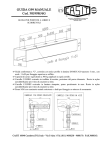
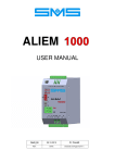
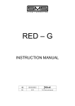
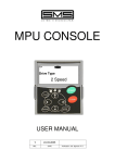
REEODA
USER MANUAL
0
19/07/13
REL.
DATE
T.M. Check and Approval
RED-E SUPPLEMENTARY KIT
FOR DOUBLE ENTRANCE
REEODA is a supplementary kit for RED-E, made up of REODA board and the necessary cables for the
connections, that provides a 2nd entrance option with its related stop switch.
REODA Board
2nd Entrance
Z4
Z3
Place the ‘bridge’ connector in position VF or 3P as your door operator requires. This selection must be the
same as the one done on the RED-E board.
Cut off the door motor supply, connect the lines coming from the control panel to MPQ1,MPQ2,MPQ3 wires
(input) and motor to wires MP1,MP2,MP3 (output).
nd
When 2 entrance door motor is driven, KE and AP2 red leds are lighted on during door opening, while KE
and CH2 are lighted on during door closing.
When a REODA board is used, the 2nd entrance is read from the related stop switch connected to wires
marked Z3 and Z4. A stop switch with N.O. or N.C. contact can be used setting properly DIP switch n.1 of
RED-E board, as indicated in the related manual. When the stop switch is closed, green led ZF2 lights on.
REEODA USER Manual Release 0, date 19-07-2013
1
REEODA MOUNTING INSTRUCTIONS
Unscrew the
retaining nut plastic
present in the
cabling
Fig.0
Kit REEODA parts:
Multi color wires sheathed
cable, cable with Minifit not
sheathed, board REODA
equipped with Flat cable
connection.
No. 4 Plastic spacers,
No. 2 terminal Minifit bridges.
Fig.2
Screw the plastic back nut and secure it firmly.
Remove the conduit and insert the unsheathed wiring
inside the device.
Fig.4
Fig.3
Insert the 4 plastic spacers
into the related holes.
2
REEODA USER Manual Release 0, date 19-07-2013
Fig.1
Insert the REODA board in the plastic spacers as in Fig.5
and connect the flat cable of REODA board into "CN18" of
RED-E board.
Prepare the wiring as shown in Fig 0. Connect the two
cables to the terminal part of the sheathed cable Minifit
previously mounted to the REODA board (silk screened as
CN21, CN22) with the correct conformation of the clamp.
Connect the cable supplied with the single non-sheathed
wiring to terminal CN3 of REODA board. Insert the single
bridge on CN5.
Fig.5
Fig.6
Connect the terminals of CN23 connector from REODA
board to transformers, as follows :
T2/00 to terminal "00" Transformer "T2";
DOOR 2 / B to terminal 125 of transformer "T2",
DOOR 1 / B to terminal 125 of transformer "T1".
REEODA USER Manual Release 0, date 19-07-2013
3
For further information and advice please contact :
SMS SISTEMI e MICROSISTEMI s.r.l. (Gruppo SASSI HOLDING)
Cap. Soc. 260.000 i.v.
Via Guido Rossa, 46/48/50 40056 Crespellano BO
R.E.A 272354 CF - Reg. Imprese Bo 03190050371 P.IVA IT 00601981202
Tel. : +39 051 969037 Fax : +39 051 969303 Technical Service: +39 051 6720710
Web : www.sms.bo.it E-mail : [email protected]
4
REEODA USER Manual Release 0, date 19-07-2013