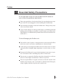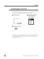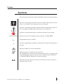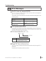
1
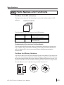
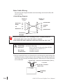
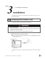
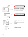
Preface
Thank you for purchasing the Profibus DP unit, hereafter referred to as the
“Profibus unit”. This unit is intended for use with the Digital Electronics
Corporation’s GP-470/570/675/870 series touch panels (hereafter referred
to collectively as the “GP”), and as an interface between the Profibus data
network and any of the abovementioned GPs.
This manual describes the procedures, settings, wiring, etc. required to perform communication on the Profibus network via the GP(s). also, each GP
has its own reference manual you can refer to for detailed GP operation
information. Before actually beginning to use the Profibus unit, please be
sure to the GP’s User’s Guide’s section “1-1 Prior to Operating the GP”.
The following GP series displays can be used with the Profibus unit.
GP-470-EG, GP-570-TC, GP-570-SC, GP-570-TV, GP-571-TC,
GP-675, GP-870V
All company or manufacturer names used in this manual are the registered
trademarks of their respective companies.
1. It is forbidden to copy the contents of this manual, either in whole or in part,
except for the purpose of the user’s personal use, without the express written
permission of the Digital Electronics Corporation of Japan.
2. The information provided in this manual is subject to change without notice.
3. This manual has been written with care, however, should the user discover any
errors or omissions, please contact the Digital Electronics Corporation and
inform them of your findings.
4. Please be aware that the Digital Electronics Corporation is not responsible for
any damages resulting from the use of its products, regardless of article 3
above.
© Copyright 1997, Digital Electronics Corporation
MS-DOS® and Windows®95 are registered trademarks of the Microsoft Corporation.
IBM® DOS® are registered trademarks of IBM.
GP-470/570 series Profibus User’s Manual
1
Preface
Table of Contents
Preface
Preface
................................................................................................................ 1
Table of Contents ......................................................................................................... 2
Essential Safety Precautions ........................................................................................ 3
Packing Box Contents ................................................................................................. 4
Symbols ....................................................................................................................... 5
Chapter 1 Introduction
1-1 Operating the Profibus Unit ............................................................................. 1-1
1-2 System Configuration ...................................................................................... 1-2
1-3 When Using Screen Creation Software ........................................................... 1-2
Chapter 2 Specifications
2-1 Profibus Specifications .................................................................................... 2-1
2-1-1 General Specifications ......................................................................... 2-1
2-1-2 Physical Specifications ........................................................................ 2-2
2-1-3 Performance Specifications ................................................................. 2-2
2-2 Part Names and Functions ............................................................................... 2-3
Chapter 3 Installation
3-1 Installing the Profibus Unit .............................................................................. 3-1
Chapter 4 Troubleshooting
4-1 Troubleshooting ............................................................................................... 4-1
4-1-1 Possible Problems ................................................................................ 4-1
4-1-2 Possible Solutions ................................................................................ 4-1
4-1-3 No Data Communication ..................................................................... 4-3
4-2 Error Messages ................................................................................................. 4-5
2
GP-470/570 series Profibus User’s Manual
Preface
Essential Safety Precautions
For the safe and correct use of the Profibus and GP series, be
sure to follow the guidelines stated below.
Due to the possibility of an electrical shock, be sure that the power supply for the GP is not plugged in when installing the Profibus unit.
Do not attempt to modify or alter the Profibus unit. Doing so may cause
a fire or an electric shock.
To prevent the danger of either personal injury or machinery/material
damage, please design your machine’s control system so it will not malfunction due to a communication problem between the GP and host controller (PLC).
To Avoid Damaging the Profibus unit:
Do not allow water, liquids, or metal particles to enter into the Profibus
unit’s case, since it can cause a malfunction or electrical shock.
Avoid storing or operating the Profibus unit in locations where it will be
exposed to direct sunlight, high temperature, excessive dust, or vibration.
Because the Profibus unit is a precision instrument, do not store or operate it in locations where something may strike or hit the unit.
Do not store or operate the Profibus unit where chemicals or acids are
stored, or where high concentrations of fumes are present.
Do not use paint thinner or organic solvents to clean the outside of the
Profibus unit. Instead, soak a soft cloth in a diluted neutral detergent,
wring it tightly, and then wipe the unit’s outside case.
GP-470/570 series Profibus User’s Manual
3
Preface
Packing Box Contents
The Profibus unit’s packing box contains the items listed below. Please
confirm that everything illustrated here has been included.
Profibus Unit
GP Series Profibus
User’s manual
(this manual)
GP Series
(470/570/675/870)
Profibus
User’s
MANUAL
Ferrite Cores (2)
This unit has been carefully packed, however, should you find any item to
be either damaged or missing, please contact your local GP distributor
immediately for service.
4
GP-470/570 series Profibus User’s Manual
Preface
Symbols
The list below describes the symbols and abbreviations used in this manual.
Indicates a potentially hazardous situation which could result in serious
injury or even death, if the instructions are not followed.
Indicates a potentially hazardous situation which could result in minor injury or equipment damage if the instructions are not followed.
Explains a situation that requires a moderate amount of user caution.
GP-PRO/PB III
PLC
*1
Indicates the GP screen editing/creation software, GP-PRO/PBIII.
Programmable Logic Controller
Indicates supplemental explanatory information is located at the bottom of
the page.
Indicates additional, relevant information.
Reference pages of related sections and topics.
The Tag Reference, Operation, Software Operation, PLC Connection, and
Parts List Manuals referred to here are those included in the GP-PRO III
or GP-PRO/PBIII for Windows®95 software package.
cd
Indicates procedure numbers. Be sure to follow these steps to perform a
particular task correctly.
GP-470/570 series Profibus User’s Manual
5
MEMO
This page intentionally left blank.
6
GP-470/570 series Profibus User’s Manual
Chapter
1
1-1 Operating the Profibus Unit
1-2 System Configuration
1-3 When Using Screen Creation Software
Introduction
This chapter describes the operation of the Profibus unit and the cautions
necessary for correct data communication.
1-1 Operating the Profibus Unit
The Profibus unit allows one of the following GP series units to be connected directly to a PLC that supports the Profibus network.
<How to set up the Profibus unit>
CPU
Connection
Diagram
Data Cable
I/F Module
GP
Types
See Cable
Wiring
Diagram 1
RS-485
Profibus-DP Module
(GP070-PF11)
GP 470E
GP-570L
GP-570S
GP-570T
GP-675
GP-870VM
Siemens
S7-300 Series
i.e. S7 315-2-DP
GP-470/570 series Profibus User’s Manual
1-1
Introduction
1-2 System Configuration
Use RS-485 cables to make the connection. This will allow for a maximum
of 64 slaves, in DIO mode, with the Seimens S7-300.
With same Seimens PLC, and using Packet mode the limilt is four (4) slaves.
RS-485
Siemens
GP
RS-485
GP
... to a maximum of 64 slaves
GP
1-3 When Using Screen Creation Software
When selecting the PLC type to use on your screen creation software, choose
“Profibus.”
For detailed selection procedures, refer to the Operation Manual
for the respective screen creation software.
• When using the GP-PRO/PB III for Windows 95 software, refer to
“1-8-2 Select a Project/Create a New Project” in the “GP-PRO/
PB III for Windows 95 Operation Manual”.
• When using the GP-PRO/PB III (DOS) software, refer to “1-5-2
Select Project” in the “GP-PRO/PB III Operation Manual”.
1-2
GP-470/570 series Profibus User’s Manual
Chapter
2
2-1 Profibus Specifications
2-2 Parts Names and Functions
Specifications
This chapter describes the specifications, names, and figures for the Profibus
unit.
2-1 Profibus Specifications
1
General Specifications
Rated voltage
Power consumption
Voltage capacitance
Insulation resistance
Ambient operating
temperature
Ambient operating
humidity
Ambient storage
temperature
Ambient storage humidity
Vibration resistance
Noise endurance
Operating Atmosphere
Grounding
GP-470/570 series Profibus User’s Manual
5 VDC ±5% (supplied by the GP unit)
Less than 3 W (Typically 1.9W)
1500 VAC, 20 mA 1 min. (between live and FG
terminals)
500 VDC, more than 10 MΩ (between live and FG
terminals)
0 to 50ºC (Do not operate in temperatures in
excess of GP’s specified range)
30 to 85% RH (Do not operate in areas where
humidity is higher than GP’s specified range)
-10 to 60ºC
20 to 85% RH (no condensation)
10 to 25 Hz (X, Y, Z directions for 30 minutes each
at 2G)
Noise voltage: 1000 Vp_p
Pulse length: 1 µs
Rise time:
1 ns (with simulator)
Free of corrosive gases
Class 3
2-1
Specifications
2
Physical Specifications
Usage
External dimensions
Weight
Cooling method
3
Performance Specifications
Memory
GP connection I/F
Communication I/F
4
Installed as an option board in GP-470/570
series(large units)’s expansion slots
167(W) x 116.1(H) x 25.1(D) (mm)
(Main unit only, including terminal block)
Approx. 330 g
Natural air circulation
2-port RAM: 1KB
GMU buses
Address bus:
16-Bit
Data bus:
8-Bit
Interrupt function: 1 ch (IRQ A, FIX)
Connector used: D-SUB 9-pin
Input/output :
Complies with RS-485 (insulated type)
Transfer rate:
12 Mbps
1500 kbps
500 kbps
187.5 kbps
93.75 kbps
19.2 kbps
9.6 kbps
Recommended cable: EIA RS-485 twisted pair
Terminating resistor: Built-in
(turns ON/OFF via DIP switches)
Usage Environment Specifications
1. Gp Data Transfer Settings
Data Transfer Speed
Data Transfer Method
RS-485
System Area Start Address
Station No.
GP Settings
*1
9.6K to 12Mbps
DB2W0
DB60W65514
0 -127
: Default Settings
*1 : The data transfer speed is automatically changed, according to the ladder
software’s specifications. Thus, setting this speed via the GP is uneeded.
*2 : Station No.s are set via the Profibus Rotary Switches.
2-2
GP-470/570 series Profibus User’s Manual
Specifications
2-2 Parts Names and Functions
Profibus Unit LED Indicators
The figure below shows the Top-Mounted placement of the Profibus module’s LED
indicators.
Top Mounted LED Unit
Power LED
G
DIA LED
R
ERROR LED
E
R
E
E
N
D
The following table shows the function of each LED indicator:
LED NAME
ERR
COLOR
RED
DIA
POWER
(NONE)
GREEN
FUNCTION
Lit: Normal Operation
Unlit: Bus is OFF or has error
Not Used
Lit: Power is ON
Unlit: Power is OFF
Terminating the First and Last Profibus Module
The first and last Profibus module must be terminated for the bus unit to operate properly. To do this, simply turn on the terminating switch on the first and last Profibus I/F
unit. (See figure below) Also, be sure to turn all other Profibus unit termination
switches OFF.
Profibus Unit Rotary Switches
The rotary switches are used to set the Profibus-DP slave node number. These must be set
to the same value as that specified in the Profibus-DP slave configuration. If the GP is to be
the last node on the Profibus-DP network, then the TERM switch must be set to the ‘ON’
position to mark the network termination. The diagram below shows an example where
the node address is set to 1, thus the rotary switches are set to ‘0 1’.
0
9
ON
1
2
8
3
7
6
5
4
0
9
1
2
8
3
7
6
5
4
1
GP-470/570 series Profibus User’s Manual
2-3
Data Cable Wiring
The following cable diagram should be used when making a cable for the Profibus-DP
cable’s connector.
<Cable Wiring Diagram>
Station 2
(9-pin)
Station 1
(9-pin)
RxD/TxD-P
(3)
(3) RxD/TxD-P
DGND
(5)
(5) DGND
VP
(6)
(6) VP
RxD/TxD-N
(8)
(8) RxD/TxD-N
Protective
Ground
Be sure to earth the PLC’s FG according to Class 3 earthing standards.
(For details, please refer to the PLC maker’s manual)
Collect all the data cable’s shield wires and connect them to the PLC’s FG. *1
Cable Data
Parameters:
Wire Gauge:
Conductor Area:
(for S7315-2-DP model)
Line A Line B, according to Profibus-DP DIN
19245 part1/4.91, section 3.1.2.3
>0.64mm >0.53mm
>0.34mm2 >0.22mm2
1* Be sure to attach the ferrite cores shown below to the data transfer cables leading to the
Profibus unit, and use a D-sub connector with a metal case. This will help to suppress the
effect of any noise created by surrounding equipment. TDK ferrite cores, or their equivalent,
are recommended.
Ferrite Cores: model name: ZCAT2035-0930A (TDK Co.),
or equivalent
D-sub 9pin connector
(Metal case)
Profibus
Unit
2-4
GP-470/570 series Profibus User’s Manual
Chapter
3
3-1 Installing the Profibus Unit
Installation
This chapter describes how to install and wire the Profibus unit and how to set
the Profibus address.
3-1 Installing the Profibus Unit
To install the Profibus unit in the GP, follow the steps below.
WARNING
Before installation
• Due to the possibility of an electrical shock, be sure the GP’s power cord is not
plugged in to the power supply.
• Be sure not to touch the surface of the printed circuit board.
c Disconnect the power cable from the GP
d Use a screwdriver to unscrew the GP rear cover’s 2 attachment screws and
remove the rear cover.
Attachment screws
Profibus Unit
Rear of GP
* This figure describes how to install the Profibus module into a GP-470 series display
unit.
GP-470/570 series Profibus User’s Manual
3-1
Installation
Protruding tabs
Be careful not to touch the surface of
the Profibus unit’s printed circuit board.
e Insert the protruding tabs of Profibus unit
into the installation holes.
Holes for installing
Be sure to install the unit so that the smooth metal
the unit
face of the Profibus unit points outward.
Be careful not to touch the surface of
the Profibus unit’s printed circuit board.
Screw holes
Attachment
Screws
3-2
f Hold the GP with your left hand and insert
the Profibus unit into its slot with your right
hand.
Be sure that the unit is seated correctly in place,
so that no gaps remain between the GP and the
Profibus unit.
g Reattach the attachment screws and secure
the Profibus unit to the GP.
GP-470/570 series Profibus User’s Manual
Chapter
4
4-1 Troubleshooting
4-2 Error Messages
Troubleshooting
This chapter describes the usual troubleshooting procedures to use when a problem
occurs with the Profibus unit.
4-1 Troubleshooting
The following section describes standard problems and their possible solutions.
1
Possible Problems
The most common problems that could occur while operating the GP are as follows:
(1) No Data Communication
Data communication does not take place between the GP and Host. In some
cases, an error message will be displayed on the screen.
For error messages, refer to “4-2 Error Messages”, and the respective GP
unit’s User’s Manuals.
(2) OFFLINE mode menu appears on the main unit during operation.
2
Possible Solutions
• For problem (1), use the following troubleshooting flowchart to diagnose the
problem’s cause and find a possible solution.
• For problem (4), the cause may be due to a main (GP) unit system error.
Please remember that the GP unit’s OFFLINE mode will display if you
touch the upper left corner of the screen within 10 seconds after start-up.
GP-470/570 series Profibus User’s Manual
4-1
Troubleshooting
WARNING
Before installing the Profibus DP unit:
• Before beginning installation, due to the possibility of an electrical shock, be
sure the main unit (GP)’s power cord is unplugged from the power supply.
This chapter describes only GP unit problems, and assumes there are no PLC problems. For PLC problem causes, please refer to the PLC maker’s Operation Manual.
4-2
GP-470/570 series Profibus User’s Manual
Troubleshooting
3
No Data Communication
If the GP can not communicate with the host, follow the flowchart described below to
find the cause of the trouble and correct the problem.
In cases where an error message is displayed on the GP’s screen, check the error code
list and correct the problem.
Refer to “4-2 Error Messages”, and the respective GP unit’s User’s Manuals
No data communication can be
performed
Turn off the GP’s power supply.
Has the PLC type info. been
entered correctly?
NO
Refer to “1-3 When Using
Screen Creation Software”,
as well as the GP-PRO/PB
III Operation Manual
YES
Has the Profibus unit been
installed correctly?
NO Insert the Profibus unit correctly and
tighten the attachment screws securely.
Refer to “3-1 Installing the
Profibus Unit”
YES
Have the
Profibus unit connector pins
been bent?
Select “Target PLC” when entering the
PLC type.
YES
Contact your local distributor.
NO
Has the address
setting for the Profibus been
set correctly?
Confirm that the rotary switch address
NO settings for the Profibus unit are correct. Refer to Section 2-2 Part Names
and Functions for details.
YES
GP-470/570 series Profibus User’s Manual
4-3
Troubleshooting
NO Check that none of the connector pins
have become bent or skewed. Then, reinstall the Profibus unit in the back of the
GP so that its connector is correctly connected.
Has the Profibus unit been
installed correctly?
YES
Turn ON the power supply
YES
Does the “ERR”
LED light up?
NO
YES
Does the
“PWR.” LED light up?
NO
Contact your local distributor for assistance and possible replacement of the unit.
Is the
network configured
correctly?
NO Configure the network correctly.
YES
NO
Does the
unit communicate
normally?
YES
OK/Finished
Assuming an authorized replacement unit has been sent to you.
YES
Does the
new Profibus unit communicate
normally?
NO
The GP unit may be defective. Contact your local distributor for further assistance
.
The original Profibus unit is
defective.
4-4
GP-470/570 series Profibus User’s Manual
Troubleshooting
4-2 Error Messages
The PLC does not respond (02:FE)
This error message is displayed when a time-out occurs while receiving data or
there is too much noise on the line.
The possible causes are described below. Select the solution below that applies to your
particular problem.
Cause
Solution
The master PLC’s power is OFF, or in Turn on the PLC power supply.
stop mode.
The PLC and the GP have been
First turn on the GP power supply, then
turned on in the wrong order.
turn on the PLC power supply after 2 to 3
seconds.
The communication cable is not
Check the wiring of the communication
connected properly.
cables, and wire them correctly.
PLC Communication Error
One possible cause of this error message is that the address value set for the tag exceeds the range specified by the processor. Check the displayed error number, and
proceed by following the respective solutions.
♦ PLC Communication Error ( 02 : x x)
02: xx
Error No.
Error No.
F6
Solution
1) Be sure that your screen data uses
only the designated LS area(s).
2) Reset the System Area (to all zeroes).
Target PLC has not been set up
This error message is displayed when data other than that used by the target PLC is
transferred.
Reinitialize the GP, and then send the correct data.
GP-470/570 series Profibus User’s Manual
4-5
Troubleshooting
MEMO
This page intentionally left blank.
4-6
GP-470/570 series Profibus User’s Manual