1
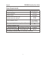
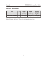
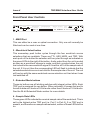
TDIF/MADI
Interface
User Guide
527-185
Issue 4
HEAD OFFICE
AMS NEVE PLC • BILLINGTON ROAD • BURNLEY
LANCS BB11 5UB • ENGLAND
TELEPHONE: +44 (0) 1282 457011 • FAX: +44 (0) 1282 417282
e-mail: [email protected]
http://www.ams-neve.com
Issue 4
TDIF/MADI Interface User Guide
AMS Neve TDIF/MADI Interface
1
Power Requirements
2
Physical Information
3
Operational Overview
4
24 Bit Extended Mode
6
Front Panel User Controls
9
Back Panel
11
TASCAM TDIF-1 Digital I/O Port Overview
12
MADI Digital I/O Port Overview
13
Tascam IF88 AES Interface
14
System Configuration
15
Customer Support
17
Issue 4
TDIF/MADI Interface User Guide
AMS Neve TDIF/MADI Interface
The TDIF/MADI unit provides an efficient means of interfacing digitally
between digital consoles (using MADI) and any 8-channel multitrack digital
tape recorder that supports TASCAM’s TDIF interface standard.
Features
· 6 TDIF ports in one interface unit, providing up to 48 channels of digital
audio
· Includes support for future use of extended bits in TDIF interface(18, 20
or 24 bits)
· Includes support for configuring any TDIF port as a 4-track 24-bit
interface
· Front panel selection of 24 bit extended mode for each of the six TDIF
ports
· Front panel selection for the wordclock source between TTL, AES, MADI
or TDIF
· Full MADI channel status support implemented
1
Issue 4
TDIF/MADI Interface User Guide
Power Requirements
Rated Voltage
90V-240V AC
Rated Frequency
50-60Hz
Rated Current
0.5A MAX
Surge Current (in rush) Cold
Surge Current (in rush) Hot
27.0A
27.0A
Earth Leakage Current
Live 0.60mA
Neutral 0.55mA
Warning for High Earth Leakage Current Required
NO
Primary Protection Fuse:
Operating Voltage
Fuse Rating and Type
Location
90V-240V AC Operation
T1.6A H 250 V AC
IEC # 1
Secondary Protection Fuse: No Secondary Fuse Fitted
2
Issue 4
TDIF/MADI Interface User Guide
Physical Information
Unit
U
Depth
mm
(inches)
Height
mm
(inches)
Approx.
Weight
Kg (Ibs)
TDIF/MADI Interface
1
370 (15)
45 (1¾)
6.5 (15)
Note: Allow an additional 100mm for cabling and connectors.
3
Issue 4
TDIF/MADI Interface User Guide
Operational Overview
The TDIF/MADI unit can run at one of two sample rates: 44.1kHz and 48kHz,
both with ±6% varispeed. This is restricted by the operating ranges defined
for a TDIF port. Note that varispeeding the tape machines will also change
the sample rate of the MADI stream. If the receiving device requires a fixed
frequency MADI stream (e.g. Capricorn) then a MADI-SRC unit will also be
required to sample rate convert between the variable frequency MADI
stream and the fixed frequency MADI stream.
The TDIF/MADI unit reads the sample rate signalled by the first (master)
TDIF port, and if valid, uses this as the sample rate for the whole unit. The
corresponding Sample Rate LED will be lit on the front of the unit. The ports
are arranged in order of priority from port 1 down to port 6. If TDIF port 1 is not
connected, or reads an invalid sample rate, then the unit scans down
through ports 2 to 6 until it finds the first valid sample rate. If a higher port is
subsequently connected than the one that has been used to set the sample
rate, then this will immediately be used instead. If all of the ports are invalid
then no sample rate is selected and no wordclock rate LED lit. If the
Wordclock Source (TTL, AES, MADI or TDIF) is not within ±6% of the sample
rate then the selected source’s green LED will flash to indicate this.
Note : A machine (DA-88, DA-38 etc.) connected to a TDIF port that is
switched off reads as a sample rate of 48kHz. To avoid any confusion, port 1
should always be active and connected to the master tape machine, thus
setting the sample rate for the TDIF/MADI unit.
Once a sample rate is set and a valid wordclock source is connected, the unit
scans all TDIF ports and enables and unmutes all ports that indicate the
sample rate of the unit. The MADI port will also be enabled. TDIF-1 Port OK
LEDs will be lit for the corresponding ports that are enabled. If no machine is
connected to the port, then the LED remains off. A flashing TDIF-1 Port OK
LED indicates that a machine is connected but at the wrong sample rate, or
the machine is at the correct sample rate but has failed to synchronise to the
unit.
4
Issue 4
TDIF/MADI Interface User Guide
The TDIF ports and the frequency of the wordclock source are continually
scanned by the unit to monitor any changes that occur. The corresponding
action required will then be taken. This allows any TDIF port to be connected
or disconnected while the unit is running, and the audio enabled or disabled
when appropriate. Again please note, as stated previously, that if you
connect a higher priority port than the one that is currently setting the sample
rate, then this new port will be used to set the sample rate. If this rate is now
different, any ports that were at the old sample rate will be switched off and
any at the new rate will be switched on (as long as the wordclock source is
within ±6% of the new sample rate).
The mapping between TDIF ports and the MADI stream is as follows:
TDIF PORT
MADI CHANNELS
1
1-8
2
9 - 16
3
17 - 24
4
25 - 32
5
33 - 40
6
41 - 48
If the TDIF-1 Port OK LED is not on, then the audio on those channels will be
muted, as are channels 49 to 56.
5
Issue 4
TDIF/MADI Interface User Guide
24 Bit Extended Mode
The audio to and from each TDIF port is capable of being formatted as four
channels of 24-bit audio rather than eight channels of 16-bit audio. The first
four channels of each TDIF port’s eight allocated channels are used in the
MADI stream. The next four are muted. This is shown below.
TDIF PORT
MADI CHANNELS
1
1 - 4(5 - 8 muted)
2
9 - 12(13 - 16 muted)
3
17 - 20(21 - 24 muted)
4
25 - 28(29 - 32 muted)
5
33 - 36(37 - 40 muted)
6
41 - 44(45 - 48 muted)
The four unused muted channels are left in so that the channels from the
ports above them do not shift down by four thus requiring the MADI Port
channel mapping to be re-assigned; i.e. the TDIF ports will always be
assigned the same group of 8 channels in the MADI stream, whether they
are set to 8-track/16-bit or 4-track/24-bit mode. Any ports not in extended
mode will of course use all of their eight channels.
6
Issue 4
TDIF/MADI Interface User Guide
The 24 bits of audio are mapped onto the actual 16-bit tracks as follows:
Track No.
(16 bit)
Channel No.
(24 bit)
16-bit to 24-bit mapping.
Bit 15 - - - - - - - - - - - - - - - Bit 0
1
channel 1
Bit 7 - - - - - - - Bit 0.00000000
2
channel 1
Bit 23 - - - - - - - - - - - - - - - -Bit 8
3
channel 2
Bit 7 - - - - - - - Bit 0.00000000
4
channel 2
Bit 23 - - - - - - - - - - - - - - - -Bit 8
5
channel 3
Bit 7 - - - - - - - Bit 0.00000000
6
channel 3
Bit 23 - - - - - - - - - - - - - - - -Bit 8
7
channel 4
Bit 7 - - - - - - - Bit 0.00000000
8
channel 4
Bit 23 - - - - - - - - - - - - - - - -Bit 8
One advantage of formatting the data in this way is that it allows the tape
contents to be auditioned without the need for a TDIF/MADI unit to decode all
24 bits. Tracks 2, 4, 6, and 8 will contain the top 16 bits of each track which is
enough to allow you to hear their contents. It should be obvious if you have a
tape that is encoded with 24-bit audio as tracks 1, 3, 5, and 7 will sound like
digital noise if listened to as a 16-bit track, and also their meter display on the
front of the tape machine will normally always show full scale when any
signal is present. This is because the bottom 8 bits of the 24-bit signals are
stored in the top 8 bits of these 16-bit tracks. Listening to 16-bit tracks in
24-bit mode will also produce recognisable audio as you will simply hear
tracks 2, 4, 6, and 8 of the tape machine appearing as the first four channels
in the MADI stream assigned for the port you are monitoring. 16-bit and
24-bit encoding can be switched between instantly simply by using the
appropriate 24-Bit/4-Track Mode Select switch on the front of the unit.
7
Issue 4
TDIF/MADI Interface User Guide
True 24 Bit Recorders
The switches on bank 1 and the first four on bank 2 set the internal
wordlength of the audio for each port as follows:
Port
1
2
3
4
5
SW1
1
2
3
4
5
6
7
8
16 Bit
0
0
0
0
0
0
0
18 Bit
0
1
0
1
0
1
20 Bit
1
0
1
0
1
24 Bit
1
1
1
1
1
SW2
6
1
2
3
4
0
0
0
0
0
0
1
0
1
0
1
0
1
0
1
0
1
0
1
1
1
1
1
1
1
DEFAULT
To obtain true 24 Bit recording the switches should be set as shown above.
8
Issue 4
TDIF/MADI Interface User Guide
Front Panel User Controls
RX
TX
MADI PORT
WORDCLOCK SOURCE
SELECT
TTL AES MADI TDIF
24 BIT/4-TRACK MODE SELECT
1
2
3
4
5
SAMPLE RATE
6
44.1 48
TDIF-1 PORT OK
1
2
3
4
5
ERROR
6
AMS
NEVE
MADI PROC
TDIF-1/MADI INTERFACE
1 - MADI Port
This can either be a coax or optical connection. Only one will normally be
fitted and can be used at one time.
2 - Wordclock Select button
This momentary push button cycles through the four wordclock source
selections that are available. These are TTL, AES, MADI, and TDIF. With
each push of the button the selection will be cycled through as indicated on
the green LEDs to the right of the button. Audio output from the unit is muted
as soon as a wordclock change is made, and then unmuted when the unit
has locked to the new wordclock signal if it is within ±6% of the sample rate of
the unit. If it is not, then the corresponding LED will flash to indicate that the
selected wordclock source is not valid for the sample rate of the unit. The unit
will boot up with the same wordclock source selection as it had when it was
last switched off.
3 - Extended Mode buttons
These six buttons are all latching switches with integral yellow LEDs. Each
TDIF port is assigned its own button. When activated, it causes that port to
format its data as 4 tracks of 24-bit audio rather than 8 tracks of 16-bit audio.
See the 24-bit Extended Mode section for more details.
4 - Sample Rate LEDs
These green LEDs indicate the nominal sample rate of the wordclock. This is
set by the highest active TDIF port (i.e. Port 1 to Port 6). If no TDIF port is
present, and therefore no sample rate selected, neither of these LEDs will be
on.
9
Issue 4
TDIF/MADI Interface User Guide
5 - TDIF Port OK LEDs
These six yellow LEDs indicate that the corresponding TDIF port is running
OK; i.e. its sample rate is the same as that shown by the sample rate LEDs,
and that the port has locked up to the unit.
6 - MADI Error LED
This red LED indicates that there is an error in the MADI stream. This can be
caused by a number of things, some of which will not cause any audible side
effects. These are : TAXI transmission error (data formatted incorrectly,
wrong sample rate, wrong number of channels) and parity error.
7 - Processor Error
This red LED indicates that the control processor (transputer) has errored.
Audio may continue to be heard but no control change will have any effect. If
a processor error does occur, please note the events which caused it.
Switching the unit off and then on again should clear the error.
Check if the error can be repeated and report it to AMS Neve plc.
10
Issue 4
TDIF/MADI Interface User Guide
Back Panel
100V - 240VAC
50HZ - 60HZ
500mA
A/S FUSE
A
B
WDCLK-IN WDCLK-OUT
TRANLINKS
75-OHMS
ON OFF
1
3
2
4
5
TDIF PORTS
6
AES-11
1 - Tranlinks
Tranlink A and B are 25-way D-type connectors and are used when
connecting the unit into a transputer network if this is required. The unit will
usually be stand alone and boot from ROM. The stand alone ROM code can
be updated using the Tranlink A port.
2 - TTL Wordclock IN (BNC)
Wordclock selection source.
3 - 75W TTL Terminator
This switch allows the 75W terminator to be enabled or disabled on the TTL
wordclock IN port. This is used for end of line termination.
4 - TTL Wordclock OUT (BNC)
The wordclock source selected on the front panel is re-buffered and sent out
on this port.
5 - AES IN (female XLR)
The AES-11 input port is used only to extract the wordclock as one of the
wordclock selection sources. The audio data in this signal is ignored.
6 - TDIF Ports
The six TDIF ports are brought in on six male 25-way D-type connectors.
The TDIF wordclock selection uses the wordclock from TDIF Port 1.
11
Issue 4
TDIF/MADI Interface User Guide
TASCAM TDIF-1 Digital I/O Port Overview
The main features of the TDIF-1 interface are as follows :-
· 8 channels of audio data in and out (one stereo pair per physical wire),
sampling frequency information, emphasis information and a
synchronising signal (DA-88 cannot slave to this).
· 25-way D-type connector; 26-way twisted pair cable.
· Audio data is inverted (negative logic), 16-bit serial data (MSB first)
followed by 8 extended bits (content unknown) in 2’s complement format
· Data transmitted at 64 times wordclock rate.
· There are 4 reserved bits and 4 user bits per audio sample. Their use is
undefined.
· Signal transmission is at CMOS levels and is unbalanced.
· Two TDIF-1 cables lengths are available - 1 metre and 5 metres.
· Only operates at 44.1kHz and 48kHz ±6%.
12
Issue 4
TDIF/MADI Interface User Guide
MADI Digital I/O Port Overview
The main features of the MADI interface are as follows : -
· High speed serial digital transmission (125 Mbits/sec).
· Single-point to single-point from one transmitter to one receiver.
· 56 channels of linearly represented digital audio.
· All channels at common sampling frequency of 32KHz to 48kHz ±12.5%.
· Resolution of up to 24 bits per channel.
· The format makes possible the transmission and reception of the
complete 28-bit channel word (excluding preamble) as specified in the
AES3-1985 document including validity, user, channel status, and parity
information.
· Transmission format is of the asynchronous simplex type and is specified
for a single 75W coaxial cable point-to-point interconnection.
13
Issue 4
TDIF/MADI Interface User Guide
Tascam IF88 AES Interface
There are jumpers on the board which can change the way each port works
to allow connection to a Tascam IF88 AES interface.
For IF88 use INSERT the jumper for that port.
For DA88 use (default) REMOVE the jumper for that port.
Port
Jumper
1
17
2
10
3
16
4
9
14
5
15
6
8
Issue 4
TDIF/MADI Interface User Guide
System Configuration
One example of a system setup would be 6 DA-88s connected to the
TDIF/MADI unit, which is then connected to a digital mixing console via the
MADI port. This is shown in Figure 2.
The TTL wordclock out from the desk is taken to the TTL IN on the
TDIF/MADI unit. The 75W Terminator would need to be switched on. The
TTL OUT of the unit is then taken to the master DA-88 which should have its
clock selection set to WORD. The other DA-88s then slave to this master
DA-88. See the DA-88 user manual for more details on synchronising
multiple DA-88s.
The TTL wordclock connection between the console and the TDIF/MADI
unit is not really required as you can select MADI as the wordclock source.
This however is not recommended and should only be used if you have no
TTL or AES source available, as the MADI wordclock contains high levels of
intrinsic jitter (80ns peak-peak or more). A hardware PLL should, however,
ensure that the clock is sufficiently jitter-free to avoid audible signal
impairment under most operating conditions.
Each TDIF port runs synchronous to the sample clock that the TDIF machine
(DA-88, DA38 etc.) is locked to. This means that the master wordclock that
the TDIF machines are locked to should be synchronous to the wordclock
source used by the TDIF/MADI unit and hence the MADI machine that it
connects to. The phase relationship does not matter as each TDIF port’s
audio is buffered in and out of the TDIF/MADI unit via a FIFO to allow them to
operate with any phase relationship. That is, as long as the TDIF machine’s
wordclock source and the TDIF/MADI interface unit’s wordclock source are
synchronous, the phase does not matter.
Note that the TTL OUT signal from the TDIF/MADI unit is simply a buffered
version of the selected wordclock, not just the TTL IN signal. Therefore, one
simple approach to wordclock configuration would be to have a permanent
TTL connection between the TDIF/MADI unit’s TTL OUT and the master
tape machine, and then simply switch between wordclock sources on the
front of the unit.
15
Issue 4
TDIF/MADI Interface User Guide
Another approach would be required if the tape machine was used as the
wordclock source for the system. This, however, is also not recommended
due to the unpredictable nature of the wordclock supplied to the TDIF port by
the tape machine.
16
Issue 4
TDIF/MADI Interface User Guide
Cable Pinouts
These are the pinouts of the cable supplied by Tascam:
Pin
Pin
Out 1 + 2
1
13
In 1 + 2
Out 3 + 4
2
12
In 3 + 4
Out 5 + 6
3
11
In 5 + 6
Out 7 + 8
4
10
In 7 + 8
Sync Out
5
9
Sync In
FS 0 Out
6
8
FS 0 In
7
Gnd
7
FS 0 Out
8
6
FS 0 Out
Sync Out
9
5
Sync In
In 7 + 8
10
4
Out 7 + 8
In 5 + 6
11
3
Out 5 + 6
In 3 + 4
12
2
Out 3 + 4
In 1 + 2
13
1
Out 1 + 2
14
Gnd
15
Gnd
16
Gnd
17
Gnd
Emph Out
18
21
Emph In
FS 1 Out
19
20
FS 1 In
FS 1 In
20
19
FS 1 Out
Emph In
21
18
Emph Out
22, 23, Gnd
24, 25
17
Issue 4
TDIF/MADI Interface User Guide
Customer Support
First-line service support for the TDIF/MADI Interface is handled by AMS
Neve’s worldwide distribution network: service queries should be addressed
in the first instance to your local distributor.
AMS Neve’s own Customer Support Department (CSD) at the Burnley,
England headquarters provides comprehensive field service backup.
Contact details are as follows:
TELEPHONE HELPLINE: +44 1282 417311
9:00am - midnight (UK time) Mon - Fri
9:00am - 6:00pm (UK time) Sat - Sun.
FAX SERVICE:
+44 1282 454804
Next working day response.
E-MAIL:
[email protected]
Next working day response.
18