1
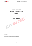
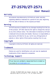
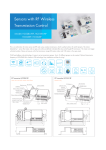
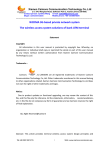
Industrial Ethernet Serial Gateway
(Modbus RTU/ASCII / Modbus TCP)
Modbus Serial/TCP Series
User Manual
REV 1.2
SST Automation
E-mail: [email protected]
WWW.SSTCOMM.COM
Modbus Serial/TCP Series
Industrial Ethernet Serial Gateway
User Manual
Catalog
1 Product Overview ................................................................................................................................................... 4
1.1 Product Function .......................................................................................................................................... 4
1.2 Product Features .......................................................................................................................................... 4
1.3 Technical specifications ............................................................................................................................... 5
2 Hardware Description ............................................................................................................................................. 6
2.1 Appearance .................................................................................................................................................. 6
2.2 Indicators ..................................................................................................................................................... 7
2.3 DIP switch.................................................................................................................................................... 8
2.4 Interface ....................................................................................................................................................... 8
2.4.1 Power interface ................................................................................................................................. 8
2.4.2 Ethernet interface .............................................................................................................................. 9
2.4.3 Serial interface ................................................................................................................................ 10
3 Instructions of Configuration Software ................................................................................................................ 13
3.1 Notes before configuration ........................................................................................................................ 13
3.2 Search equipment....................................................................................................................................... 14
3.2.1 Search all equipment in Ethernet .................................................................................................... 14
3.2.2 IP search.......................................................................................................................................... 15
3.3 Configuration ............................................................................................................................................. 17
3.3.1 Mode selection ................................................................................................................................ 18
3.3.2 Ethernet parameters ........................................................................................................................ 19
3.3.3 Serial parameters ............................................................................................................................ 19
3.3.4 ID mapping (Advanced parameters) ............................................................................................... 21
3.3.5 Modbus parameters (Advanced parameters)................................................................................... 22
3.3.6 Priority control (Advanced parameters).......................................................................................... 23
3.3.7 Advanced (Advanced parameters) .................................................................................................. 24
3.3.8 OK, Cancel and Help ...................................................................................................................... 25
3.4 Locate ........................................................................................................................................................ 26
3.5 Remote reset .............................................................................................................................................. 27
3.6 New (offline configuration) ....................................................................................................................... 27
3.7 Open........................................................................................................................................................... 28
3.8 Save ........................................................................................................................................................... 29
3.9 Communication test ................................................................................................................................... 31
4 Typical Application ............................................................................................................................................... 32
4.1 Multiple Ethernet master connect with multiple serial slave ..................................................................... 32
4.2 Multiport serial master connect with multiple Ethernet slave ................................................................... 33
4.3 Serial master connect with serial slave via Ethernet .................................................................................. 34
5 Installation ............................................................................................................................................................ 35
5.1 Machine Dimension ................................................................................................................................... 35
WWW.SSTCOMM.COM
2
Modbus Serial/TCP Series
Industrial Ethernet Serial Gateway
User Manual
5.2 Installation Method .................................................................................................................................... 35
WWW.SSTCOMM.COM
3
Modbus Serial/TCP Series
Industrial Ethernet Serial Gateway
User Manual
1 Product Overview
1.1 Product Function
Modbus Serial/TCP series gateway can achieve the interconnection between Ethernet (Modbus TCP protocol)
devices and serial (Modbus RTU/ASCII) devices. The Modbus Serial/TCP series gateway supports dual Ethernet
ports, built-in switch; the serial side supports single/dual/four serial port. Each port supports both RS485 and
RS232, but the same product can only achieve one type of port, users can specify the port according to actual
needs when ordering.
Modbus Serial/TCP series gateway products type list:
Product Type
Ethernet end protocol
Serial protocol
Serial number
GT200-MT-RS
Modbus TCP
Modbus RTU/ASCII
Single serial port
GT200-MT-2RS
Modbus TCP
Modbus RTU/ASCII
Dual serial port
GT200-MT-4RS
Modbus TCP
Modbus RTU/ASCII
Four serial port
1.2 Product Features
♦
Operating mode:
Modbus RTU/ASCII slave mode: Modbus TCP masters communicate with Modbus RTU/ASCII slaves
through the gateway;
Modbus RTU/ASCII master mode: Modbus RTU/ASCII masters communicate with Modbus TCP salves
through the gateway.
♦
Dual Ethernet interface , built-in switch, support cascade , can be used in a ring network ,save field
connection cables and switches;
♦
GT200-MT-RS: One RS485 interface or RS232 interface, 1KV electromagnetic isolation;
GT200-MT-2RS: Two RS485 interfaces or RS232 interfaces, 1KV electromagnetic isolation;
GT200-MT-4RS: Four RS485 interfaces or RS232 interfaces 1KV electromagnetic isolation.
WWW.SSTCOMM.COM
4
Modbus Serial/TCP Series
Industrial Ethernet Serial Gateway
User Manual
♦
Ethernet 10/100M self-adaptive;
♦
Slave ID mapping function;
♦
Packet request is automatically routed to the serial port;
♦
Network security settings;
Limit the IP address range of clients’ communication machine;
Login password can be set;
♦
Debugging function;
♦
Provide easy-to-use configuration software SST-MT-CFG.
1.3 Technical specifications
[1] Slave mode: Support 4 Modbus TCP master communication simultaneously, and can support 32
command request simultaneously;
[2] Master mode: Support visiting 4 different IPs or Modbus TCP slaves of different ports;
[3] Every serial interface is all RS485 or RS232, half-duplex, and baud rate support: 1200, 2400, 4800, 9600,
19200, 38400, 57600, 115200 and 230400bps optional; parity: none, odd and even optional; 1 or 2 stop bits;
[4] Power supply: 24VDC (11V ~ 30V), 130mA (24VDC);
[5] Working temperature: -4℉~140℉(-20℃~60℃), relative humidity: 5% ~ 95% (non-condensing);
[6] External Dimensions (W*H*D): 1.57 in*4.92 in*4.33 in (40mm*125mm*110mm);
[7] Installation: 35mm rail;
[8] Protection class: IP20;
[9] Test standard: EMC test standards.
WWW.SSTCOMM.COM
5
Modbus Serial/TCP Series
Industrial Ethernet Serial Gateway
User Manual
2 Hardware Description
2.1 Appearance
Serial interface Ⅳ
Serial interface Ⅲ
Indicators
Power interface
Dual Ethernet interface
Serial interfaceⅠ
Serial interface Ⅱ
Configuration switch
Notes:
1.
The picture above shows the appearance of GT200-MT-4RS;
2.
GT200-MT-2RS , two serial ports : serial I and serial II;
3.
GT200-MT-RS, one serial port: serial I.
WWW.SSTCOMM.COM
6
Modbus Serial/TCP Series
Industrial Ethernet Serial Gateway
User Manual
2.2 Indicators
product
model
GT200-MTRS
GT200-MT2RS
Indicators
Status
Descriptions
RX
Blinking(Green)
Serial port is receiving data
TX
Blinking (Green)
Serial port is transmitting data
RX blinking(Green)
Serial portⅠis receiving data
TX blinking (Green)
Serial portⅠis transmitting data
RX blinking (Green)
Serial portⅡis receiving data
TX Blinking(Green)
Serial portⅡis transmitting data
Blinking(Green)
Serial portⅠis receiving data
Blinking(Yellow)
Serial portⅠis transmitting data
Blinking(Green)
Serial portⅡis receiving data
Blinking(Yellow)
Serial portⅡis transmitting data
Blinking(Green)
Serial portⅢ is receiving data
Blinking(Yellow)
Serial portⅢ is transmitting data
Blinking(Green)
Serial portⅣis receiving data
Blinking(Yellow)
Serial portⅣis transmitting data
Green on
Slave mode: At least one Modbus TCP
connection has been established;
Master mode: Modbus TCP connection has
been established
Blinking(Green)
Slave mode: Modbus TCP no connection;
Master mode: Modbus TCP connection has
not been established
Blinking(Red)
Modbus TCP connection is disconnected and
no longer exists; Obtain IP config via DHCP
Blinking(Red)
(lasts 3 seconds)
Modbus TCP connection is disconnected
Green on
Serial port ready to transmit and receive data
Blinking(Red)
Automatic routing conflict
Red on
Equipment failure or firmware update failed
Simultaneously on
Start status
Blink alternately
Configuration Mode
Blink alternately
(lasts 3 seconds)
Using locate function
ENS on, SNS off
Firmware update mode
Ⅰ
Ⅱ
Ⅰ
GT200-MT4RS
Ⅱ
Ⅲ
Ⅳ
ENS
Modbus
Serial/TCP
series
SNS
ENS (Orange) and
SNS (Orange)
(Orange: Red and
green light on at the
same time)
WWW.SSTCOMM.COM
7
Modbus Serial/TCP Series
Industrial Ethernet Serial Gateway
User Manual
2.3 DIP switch
The DIP switch is located at the bottom of the gateway, bit 1 is mode bit and bit 2 is function bit.
Off
On 1 2
Mode (bit 1)
Function (bit 2)
Off
Off
Off
On
Description
Run mode, allowing reading and writing of configuration
data
Run mode, forbidding reading and writing of configuration
data (configuration data protection switch )
Configuration mode, IP address is 192.168.0.10 (fixed),
On
Off
this mode can read and write configuration data but cannot
finish communication between Modbus TCP and Modbus
RTU devices
On
On
Firmware update mode, IP address is 192.168.0.10, this
mode can only update firmware
Notes:
Restart Modbus Serial/TCP series gateway (power off and power on) after resetting the configuration
to make the configuration take effect!
2.4 Interface
2.4.1 Power interface
Modbus Serial/TCP series gateway uses a 24V DC power supply. The power interface uses a 3-pin 7.62mm both
ends of the closed-end terminals, defined as follows:
WWW.SSTCOMM.COM
8
Modbus Serial/TCP Series
Industrial Ethernet Serial Gateway
User Manual
GND
1
NC
2
24V+
3
Pin
Function
1
GND
2
NC, not connected
3
24V+ , DC 24V
Power supply wiring is shown as below:
GND
1
GND
NC
2
24V+
24V+
3
DC power: +24V
Power interface
2.4.2 Ethernet interface
Ethernet interface usesRJ-45 connector, its pin (standard Ethernet signal) is defined as below:
WWW.SSTCOMM.COM
9
Modbus Serial/TCP Series
Industrial Ethernet Serial Gateway
User Manual
Pin
Signal Description
S1
TXD+, Tranceive Data+, Output
S2
TXD-, Tranceive Data-, Output
S3
RXD+, Receive Data+, Input
S4
Bi-directional Data+
S5
Bi-directional Data-
S6
RXD-, Receive Data-, Input
S7
Bi-directional Data+
S8
Bi-directional Data-
2.4.3 Serial interface
Modbus Serial/TCP series gateway uses a 3-pin 5.08mm closed terminal of two ends. Ports support RS485 or
RS232.
Pin of RS232 interface is defined as below:
TX
1
RX
2
GND
3
Pin
Signal Description
1
TX, connect with RX of user device
2
RX, connect with TX of user device
3
GND
Pin of RS485 interface is defined as below:
D+
1
D-
2
GND
3
WWW.SSTCOMM.COM
10
Modbus Serial/TCP Series
Industrial Ethernet Serial Gateway
User Manual
Pin
Signal Description
1
D+, RS485
2
D-, RS485
3
GND
The RS485 interface of the Modbus Serial/TCP series gateway is a standard one, and the RS485
characteristics of the product are shown as follows:
1. The basic characteristics of RS485 transmission technology
① Network topology: Linear bus, there are active bus terminal resistors at both sides.
② Transmission rate: 1200 bps~115.2Kbps.
③ Media: Shielded twisted-pair cable and also can cancel the shielding, depending on environmental
conditions (EMC).
④Site numbers: 32 stations per subsection (without repeater), and can up to 127 stations (with RS485
repeater).
⑤Plug connection: 3-pin pluggable terminal.
2. The main points on RS485 transmission equipment installation
①All the equipment are connected with RS485 bus;
②Subsection can be connected up to 32 sites;
③The farthest end of each bus has a termination resistor—120Ω 1/2W to ensure reliable operation of the
network.
WWW.SSTCOMM.COM
11
Modbus Serial/TCP Series
Industrial Ethernet Serial Gateway
User Manual
485+
1
485-
2
RS485 device
D+
DGND
3
RS485 interface
485+
485RS485 device
…
485+
485RS485 device
WWW.SSTCOMM.COM
12
Modbus Serial/TCP Series
Industrial Ethernet Serial Gateway
User Manual
3 Instructions of Configuration Software
Double click the configuration software and finish the configuration of Modbus Serial/TCP series gateway.
(GT200-MT-4RS as an example below)
Notes:
The factory setting of Modbus Serial/TCP series gateway is 192.168.0.10, subnet mask is 255.255.255.0, and
gateway address is 192.168.0.1.
(When users click the “Advanced” tab in the “Restore Factory Settings ", the default IP address configuration
is DHCP.)
3.1 Notes before configuration
SST-MT-CFG is a product based on Windows platform, and used to configure parameters of Modbus
Serial/TCP series gateway.
Before running the software, make sure the user’s computer and Modbus Serial/TCP series need to be in the
same network.
Double-click the icon to access the main interface:
WWW.SSTCOMM.COM
13
Modbus Serial/TCP Series
Industrial Ethernet Serial Gateway
User Manual
3.2 Search equipment
Before configuring parameters of Modbus Serial/TCP, users need to search the gateway using the software.
The software provides two ways to search the gateway.
3.2.1 Search all equipment in Ethernet
Click “Search Equipment” button of the main interface, the software will search all the available Modbus
Serial/TCP series gateway equipment and list them in the main interface.
WWW.SSTCOMM.COM
14
Modbus Serial/TCP Series
Industrial Ethernet Serial Gateway
User Manual
3.2.2 IP search
Click “IP Search” button of the main interface will pop up a dialog box which demands you to input IP
address.
WWW.SSTCOMM.COM
15
Modbus Serial/TCP Series
Industrial Ethernet Serial Gateway
User Manual
After entering the correct IP address, the software will search Modbus Serial/TCP series gateway with this IP
address in the network, and list the information of the equipment in the main interface.
Notes:
WWW.SSTCOMM.COM
16
Modbus Serial/TCP Series
Industrial Ethernet Serial Gateway
User Manual
If users select the “IP Search”, users need to enter correct IP address or it will not search equipment.
3.3 Configuration
Select the equipment to be configured in the list, and the “Locate”, “Configuration”, “Remote Reset”, “New”,
“Open” and “Save” buttons will become available:
Click “Configuration” button, a password authentication dialog box will pop up if the equipment has been set
with a password:
Pass the password authentication or then enter configuration interface with no password:
WWW.SSTCOMM.COM
17
Modbus Serial/TCP Series
Industrial Ethernet Serial Gateway
User Manual
3.3.1 Mode selection
Now Modbus Serial/TCP series gateway supports four operating modes:
Modbus RTU slave mode——Modbus TCP master communicate with Modbus RTU slave through the
gateway;
Modbus RTU master mode——Modbus RTU master communicate with Modbus TCP salve through the
gateway.
Modbus ASCII slave mode——Modbus TCP master communicate with Modbus ASCII slave through the
gateway;
Modbus ASCII master mode——Modbus ASCII master communicate with Modbus TCP salve through the
gateway.
Operating mode of Modbus Serial/TCP series gateway is defined by the role of master or slave of serial
equipment, for example, when you want to achieve the communication between Modbus TCP master devices and
Modbus RTU/ASCII slave devices, users need to select “RTU/ASCII slave mode” of Modbus Serial/TCP series
gateway.
WWW.SSTCOMM.COM
18
Modbus Serial/TCP Series
Industrial Ethernet Serial Gateway
User Manual
3.3.2 Ethernet parameters
Ethernet parameters include: “Name”, “Assign IP Mode”, “IP Address”, “Subnet Mask”, “Default Gateway”,
“DNS1” and “DNS2”.
Name——enter a name to identify the device in order to distinguish from other equipment;
Assign IP Mode——set the IP address configuration mode of the equipment;
IP address——set IP address of the equipment;
Subnet Mask——set subnet mask of the equipment;
Default Gateway——set gateway address of the equipment;
DNS1——0.0.0.0 (currently only support 0.0.0.0)
DNS2——0.0.0.0 (currently only support 0.0.0.0)
Notes:
The name cannot have spaces, up to 20 characters.
3.3.3 Serial parameters
Serial parameters include: “Baud Rate”, “Parity”, “Stop bits” and “Data Bits”.
WWW.SSTCOMM.COM
19
Modbus Serial/TCP Series
Industrial Ethernet Serial Gateway
User Manual
Baud rate——1200、2400、4800、9600、19200、38400、57600、115200、230400bps;
Parity——None, Odd, Even;
Stop bit——1, 2;
Data bit——8 (currently only support 8 data bits)
Notes:
GT200-MT-2RS/GT200-MT-4RS gateway: You only need to set one serial port, if all serial port parameters
are consistent, and then click "Apply to All Serial Ports”, all serial port parameters can be configured to the
current display serial port parameters. Click “Display Serial Information” will pop up:
WWW.SSTCOMM.COM
20
Modbus Serial/TCP Series
Industrial Ethernet Serial Gateway
User Manual
3.3.4 ID mapping (Advanced parameters)
When you select RTU slave or ASCII slave mode, and only configure the basic configuration, this cannot be
configured.
When you select RTU master or ASCII master mode, please indicate which server the request packets are
sent to.
Virtual Slave ID Range——enter an ID range, the left is minimum, the right is maximum (no more than
247);
Offset of Slave ID——D-value of virtual ID and actual ID (can be negative);
Actual Salve ID——by clicking “Set” button to calculate;
When selecting “RTU/ASCII slave mode”, users need to specify the serial port to be mapped.
When selecting “RTU/ASCII master mode”, users need to set “IP of Target TCP server”, that is the IP
address of the server to be connected.
After setting “Virtual slave ID Range” and “Offset of Slave ID”, click “Set” button, “Actual Salve ID” value
is automatically calculated.
When users click “Add” button, users can add a message in “Slave ID Mapping Table”.
When users want to modify the added information, users fist select the information you want to modify, and
WWW.SSTCOMM.COM
21
Modbus Serial/TCP Series
Industrial Ethernet Serial Gateway
User Manual
then set “Virtual Slave ID Range” and “Offset of Slave ID”, click “Modify” button.
When users want to delete the added information, users need to select the information you want to delete, and
click “Delete” button.
Tips:
1. “Add” and “Modify” button both have “Set” function, users do not need to click “Set” then click “Add”
or “Modify”.
2. Support up to 4 group ID mapping.
3.3.5 Modbus parameters (Advanced parameters)
When you select RTU slave or ASCII slave mode, and only configure the basic parameters, the item does not
need to be configured.
Set "Time Interval between Characters", "Response Timeout" and "Delay between Polls" of Modbus
RTU/ASCII in the following interface:
Notes:
When users use GT200-MT-2RS/GT200-MT-4RS gateway, you only need to set one serial port if all serial
port parameters are consistent, and then click "Apply to All Serial Ports”, all serial port parameters can be
configured to the current display serial port parameters. Click “Display Serial Information” will pop up:
WWW.SSTCOMM.COM
22
Modbus Serial/TCP Series
Industrial Ethernet Serial Gateway
User Manual
3.3.6 Priority control (Advanced parameters)
When users select RTU slave or ASCII slave mode, and only configure the basic configuration, this does not
need to be configured. (Modbus Serial/TCP series gateway does not support this feature temporarily)
Ethernet speed is faster than serial port, and it will cause queuing of frame, then you can set priority of
frames.
After enabling “Priority Control”, users can set the parameters they want and only “RTU/ASCII salve mode”
supports the function:
Specify the master——the requests of specified master are prior to transmit.
Specify the request——the requests of specified slave ID (virtual ID) or function codes are prior to transmit.
Priority of requests:
Conditions
Priority
Comply with specified master, and comply with specified request
High
Comply with specified master, or comply with specified request
General
Not comply with priority conditions
Low
Use method of “Add”, “Modify” and “Delete” is the same with “ID mapping”.
WWW.SSTCOMM.COM
23
Modbus Serial/TCP Series
Industrial Ethernet Serial Gateway
User Manual
3.3.7 Advanced (Advanced parameters)
When you select RTU slave or ASCII slave mode, and only configure the basic configuration, this cannot be
configured.
Advanced parameters include: "Password", "Confirm Password", "Use default port", "Port Number",
"Start-up Delay of Serial Port", "Restore Factory Settings", "TCP Connect Idle Time", and "Limitation of
communication IP Range".
Password——after setting the password, users need to enter the password when logging in the equipment
WWW.SSTCOMM.COM
24
Modbus Serial/TCP Series
Industrial Ethernet Serial Gateway
User Manual
again. If users want to delete the password, just set your password to empty.
Restore Factory Settings——when users click the button, the previous configuration information will be lost.
TCP Connect Idle Time and Keep-Alive——When a TCP connection idle time reaches the set value, if
“Keep-Alive” is selected, then transmit keep-alive message; If not, then disconnect the TCP connection.
Limitation of communication IP range——Set the range of communication IP to limit the client to connect to
Modbus Serial/TCP.
3.3.8 OK, Cancel and Help
After configuring parameters, users need to click “OK” button to write the configuration to the equipment. If
you do not want to write to the configuration, click “Cancel” button.
(1) OK:
WWW.SSTCOMM.COM
25
Modbus Serial/TCP Series
Industrial Ethernet Serial Gateway
User Manual
Save: Save the configuration as ". inf " format to the local disk;
Download: Download the configuration to the equipment;
Save and Download: Save to the hard disk and download to the equipment.
(2) Cancel:
Yes: Save to the hard drive and close;
No: No save and direct close.
(3) Help:
Open the software manual.
3.4 Locate
When users manage multiple Modbus Serial/TCP gateways, you can use “Locate” function to determine
equipment that you want to configure.
Users click on the “Locate” button, and the equipment is in Ethernet, the ENS and SNS red indicator of the
equipment will flash alternately 3 seconds then the users can find it.
WWW.SSTCOMM.COM
26
Modbus Serial/TCP Series
Industrial Ethernet Serial Gateway
User Manual
3.5 Remote reset
The function of “remote reset” is restarting the selected equipment. Click remote reset, ENS and SNS red
indicators will be on at the same time
Select the equipment in the list first, click “Remote reset” button, it will pop up a confirmation dialog, then
click “OK” to complete the operation.
3.6 New (offline configuration)
Click “New” and select an equipment message dialog box:
WWW.SSTCOMM.COM
27
Modbus Serial/TCP Series
Industrial Ethernet Serial Gateway
User Manual
Enter into the new configuration interface; all of the data is the factory defaults.
3.7 Open
Open: Including open online and open offline;
Open online (as shown below ) : is equivalent to import, select the device from the list , click the " Open " , if
the equipment type of the gateway is the same with the opened configuration file type , and the equipment allows
remote configuration , open successfully ; otherwise , it will show the appropriate error message.
Open offline (as shown below): Open directly without choosing the equipment (One of the off-line
configuration functionality)
WWW.SSTCOMM.COM
28
Modbus Serial/TCP Series
Industrial Ethernet Serial Gateway
User Manual
3.8 Save
Save: is equivalent to export, select a device and click “Save, save the parameters of the device as “.inf”
format on the hard disk
WWW.SSTCOMM.COM
29
Modbus Serial/TCP Series
Industrial Ethernet Serial Gateway
User Manual
Notes:
The configuration file can be opened with notepad, you can modify the data inside; make sure the accuracy
of the modified data;
Please don’t modify keywords, don’t add a space.
WWW.SSTCOMM.COM
30
Modbus Serial/TCP Series
Industrial Ethernet Serial Gateway
User Manual
3.9 Communication test
"Communication Test" can send Modbus TCP request manually, it is convenient for user's debugging serial
equipment, click "Communication Test" to enter:
IP Address: the IP address of equipment needs to be connected;
Port: the port number of equipment needs to be connected; the default value is 502;
Function: support function code: 1, 2, 3, 4, 5, 6, 15 and 16;
Slave ID: the slave address (virtual ID);
Start Address: the start address of registers or coils, decimal;
Number: the number of registers or coils, decimal;
Data (up): the data needs to be sent, hex;
State: the response state, "No response", "Right response", "Wrong response";
Data (down): show the content of response message.
Note: the input data is HEX data, it must comply with data format like "12 ff 0c". The data format is this one too.
WWW.SSTCOMM.COM
31
Modbus Serial/TCP Series
Industrial Ethernet Serial Gateway
User Manual
4 Typical Application
Modbus Serial/TCP series gateway can connect Modbus master/slave devices to Ethernet in order to realize
the communication between Ethernet and serial devices.
The following is some typical application of Modbus Serial/TCP series gateway. (Take GT200-MT-4RS as an
example)
4.1 Multiple Ethernet master connect with multiple serial slave
GT200-MT-4RS supports dual Ethernet ports, built-in switch function. Support more than one independent
serial port. When serial is RS485, it can connect nearly 100 Modbus slave devices to the Ethernet.
Host
Computer
Modbus TCP
Master
Modbus Network Ⅰ
Modbus Network Ⅲ
……
……
GT200-MT-4RS
Comprehensive
security
Temperature
Controller
Inverter
Moisture
Analyzer
Modbus Network Ⅱ
Modbus Network Ⅳ
……
……
Motor protection
devices
WWW.SSTCOMM.COM
Temperature and
humidity
controller
Process control
logger
HMI
Inverter
32
Text display
Temperature
table
Multifunction
energy monitoring
instruments
Modbus Serial/TCP Series
Industrial Ethernet Serial Gateway
User Manual
4.2 Multiport serial master connect with multiple Ethernet slave
Modbus RTU/ASCII
Master
RS-485
GT200-MT-4RS
Ethernet
Modbus TCP
Slave
WWW.SSTCOMM.COM
Modbus TCP
Slave
33
Modbus Serial/TCP Series
Industrial Ethernet Serial Gateway
User Manual
4.3 Serial master connect with serial slave via Ethernet
Serial devices communicate via Ethernet, not subject to the limitation of the transmission distance.
RTU/ASCII Master
Ethernet
RS-485
GT200-MT-4RS
Modbus Network �
Modbus Network �
…
Comprehensive
security
Temperatur
e Controller
…
…
Inverter
Moisture
Analyzer
…
Motor
protection
devices
Temperature
and humidity
controller
Process control
logger
Modbus Network �
Modbus Network �
WWW.SSTCOMM.COM
…
GT200-MT-4RS
…
…
HMI
34
Inverter
Text display
…
Temperature
table
Multifunction
energy
monitoring
instruments
Modbus Serial/TCP Series
Industrial Ethernet Serial Gateway
User Manual
5 Installation
5.1 Machine Dimension
Size: 1.57 in (width)*4.92 in (height)*4.33 in (depth)
5.2 Installation Method
35mm DIN rail mounting
WWW.SSTCOMM.COM
35
Modbus Serial/TCP Series
Industrial Ethernet Serial Gateway
User Manual
WWW.SSTCOMM.COM
36