1
the Club Of Microprocessor Programmers, Users, and Technical Experts
Georgia Marszalek, Editor
•
David Graves, Editor
•
Doug Hall, Hardware Consultant
Sponsored by National Semiconductor Corp., Santa Clara, CA. 95051
SUPPORT CIRCUITS,
FASTER BOBOA'S ADDED
Less than one year ago we entered the 8080A marketplace
with our INS8080A - a pin-for-pin, function-for-function
replacement for you-know-who's MPU. But that was only
the start. Since then we've added two more versions of
that microprocessor, as well as a complete family of support circuits.
The new versions of our original 2-/J.s cycle time INS8080A
are the INS8080A-1, which has a 1.3-/J.s cycle time, and the
INS8080A-2, with a 1.5-/J.s cycle time.
In addition to the faster 8080A's, we now offer ten types
of interface circuits to support 8080A system design.
• DP 8212 is a 8-bit I/O port that you can use to implement all major peripheral and MPU I/O system functions.
• INS8255 is a programmable peripheral I/O interface that
features direct bit set/reset capability.
• DP8301 is a microprocessor interface latch element
(M I LE) with on-chip status flags for 'handshake' control
and interrupt generation. It drives TTL, NMOS, PMOS, and
CMOS circuitry.
• DP8224 is a crystal-controlled clock generator and
driver, which also provides a status strobe and oscillator
outputs for external circuits.
• DP8228/8238 are system controller and bus driver circuits that
generate all needed read/write
control signals, provide drive and
isolation for the SOSOA's bidirectional data bus, and a userselected single-level interrupt
vector.
• DPS304 is an 8-bit bidirectional
bus transceiver with high active
outputs to both ports, a Tri-State®
chip enable control, and transmit/
receive control.
Vol. 3, No.6, June 1977
Line-&Y-Line Resident
Assemhler For
"SC/MP"
MPO EnhOllces
Development System
National is now offering a line-by-line resident assembler
firmware kit, designed for use with its SC/MP LCDS (Low
Cost Development System). Known as SUPAK, the $300
assembler is contained in eight PROM/ROM devices that
can be plugged into a blank ROM/PROM card (lSP-SB/004B)
which is available from National. The entire assembled card
is then inserted into the LCDS/teletype system.
SUPAK is the only firmware kit of its kind. It greatly
enhances the flexibility and capability of the SC/MP LCDS,
making it both the most inexpensive and effective SC/MP
development tool. SUPAK is a 4K byte package that consists of three programs: a line-by-line assembler, a paper
tape line editor and a PROM tape punch program.
The line-by-line assembler accepts a program in limited
assembly language from a keyboard or paper reader, and
then assembles it directly into RAM.
The paper tape line editor, which allows insertion, deletion
or replacement of lines of program source code, punches
either leader or trailer.
• INSS251 is a universal communications interface (USART) for data
communication in SOSOA and
other bus-structured systems.
The PROM tape punch program punches the contents of a
specified memory range, in BPNF or complemented binary
format, onto paper tape. This tape could be used to program
memories using a standard, commercially available PROM
programmer such as the DATA I/O.
• DPS216/S226 are I/O buffer
drivers (4-bit parallel transceivers) suited to both SOSOA
and general MPU applications.
SUPAK requires the LCDS firmware, but will run on either a
SC/MP or a SC/MP II (n-channel) LCDS. It comes as a set of
eight MM5204/MM5214 ROM IC's, designated ISP-8F/111.
COMPUTE Newsletter. Vol. 3 No.6
IIWtllUal
palQao
59 secs. It was developed using an IMp·16P with 16K and
the IMP·16 Disc system.
SC/MP Program SL0047A·PLOT
(from Jermyn MicroComputer Center, Kent, England)
Program Listing - see page 3
Source paper tape - $5.00 each
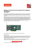
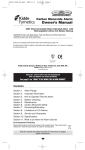
A sample plot of a SINE wave drawn on a Teletype by the
PLOT routine is shown below.
GRAPH PLOTTER FROM RAM A JERMYN UTILITY PROGRAM
~
I~
2~
4~
3a
sa
60
----+---------+---------.--------.+---------.---------+---------+----+
*
*
o
la
2a •
3a
4~
50
60
o
Ia
20
30
40
*50
60
2a
30
50
60
20
30
sa
---4---------+-----.---+---------+---------+---------+---------.----.
---+---------+---------+---------+---------+---------.---------+----.
10
I
2
3
4
5
6
7
15
9
10
II
12
13
14
15
I6
17
18
19
20
21
22
23
24
25
26
27
215
29
31!J
31
32
33
34
35
36
37
38
39
40
41
42
43
44
45
46
/* TIMET' PROGRAM FOR UP TO 99KRS 59MIN 59SEC
*n
DECI.AP E (A. B. C. D. E. F. I) WORD;
DECI.APE (AA. AS. AC. AD. AE. AI") WORD;
DECI.APE SP 1.1 TERAl.I.Y '28K';
DECLARE CR I.ITERAl.I.Y '0OH';
DECLARE 1.1" I.ITERAl.I.Y '0AH ';
PUTC:ASMPROC( I. 7E59K);
STI DO la0 TO 25;
CAl.1. PUTC( I. 1");
E~D ST;
1"1.1 00 Fa0 TO 9;
AF= F+30K;
EI.: DO E=0 TO 9;
AEa E+30KI
DI. : DO D- e TO 5;
ADaD+3I!JK;
CI.IDO C"0 TO 9;
AC=C+30K;
B1.: 00 B=I!J TO 5;
AB=B+30K;
A1.:DO A=I!J TO 9;
AA=A+ :iSK;
CAl.1. TI ME( 65110) ;
SL:DO la0 TO 30;
CAl.1. PUTC( SP) ;
END SI.;
CAl.1. PUTC( AI") ;
CAl.1. PUTC( AE) ;
CAl.1. PUTC( SP) ;
CAl.1. PUTC( SP) ;
CAl.1. PUTC( AD);
CAl.1. PUTC( AC);
CAl.1. PUTC( SP) ;
CAl.1. PUTCCSP);
CAl.L PUTCCAB);
CAl.1. PUTCC AA);
CAl.1. PUTCC CR) ;
CAl.1. PUTC(I.F>J
END A1.;
END BI.;
END CI.;
END DI.;
END EL;
EN D' Fl.;
EOF STJ
?
I~
Cl.
~~~
2~
J~
*40
50
60
I
Programming Tidbit
When using the PACE or IMP-16 you may use a version of
the following assembly instruction to load an ASCII character
into one of the Accumulators
LI 0, '9'/256
an ASCII instruction will result in object code that will result in
an ASCII 9 or X'39 to be loaded left justified in AC0 when
executed.
SM/PL TIMER PROGRAM
SM/PL-A High Level
Language For IMP-16
A few words on the SM/PL Compiler for IMp·16 •.•
•
SM/PL (Smart or Simple Programming Language) is a
high level language compiler for the IMP·16 only.
•
To compile a SM/PL program and accommodate the
compiler 16K of R/W memory is necessary.
•
It is not a supported product and is only available
through the Microprocessor Users Group at a cost of
$100.00.
•
The $100.00 price tag includes the source listing,
SM/PL Programming Manual and the object (machine
language) tape.
•
Ordering SM/PL is done by sending a check or
Purchase Order to Compute/208, National Semi·
conductor, 2900 Semiconductor Dr, Santa Clara,
Ca. 95051 (see the library order form on page 15).
•
The August 1976 issue of the COMPUTE (Vol. 2 #8)
newsletter contains a description of the language
features.
(by Bob Edwards
LECO Corporation
(616) 983·5531)
This is a SM/PL program that works with a 1200 baud CRT.
This program prints the time from 0 to 99 hrs 59 mins and
2
COMPUTE Newsletter. Vol. 3 No.6
1
2
3
4
5
6
7
8
9
TITLE PLOT, 'SC./MP PLOTTER FROM RAM'
; LIBRARY PROGRAM SL0047A
THIS PROGRAM FETCHES DATA STORED IN RAM
AND DISPLAYS THE CONTENT IN GRAPHICAL
FORM ON THE TEL.ETYPE CONSOLE
AFTER LOADING SET THE TARGET PROGRAM
COLINTER TO HEX 0001 (INITIAL.ISE) AND
THEN RUN
10
11
12
18
14
15
16
17
18
19
20
21
22
23
24
25
26
27
28
29
30
31
32
33
0001
0002
000:3
07FD
07FF
0000
0004
07FC
7AE2
OOOD
OOOA
0008
FFFF
FFF6
FFBF
0020
0007
34
003F
THI~:
PROGRAM WIL.L RUN WITTHIN AN L C. D. S
CONTAINING ZK BYTE~: OF RAM (ISP-8Cl002).
DATA FOR PLOTTING IS FETCHED FROM LOCATION
MDATA UPWARDS AND L.OOPS AROUND AT LOCATION
DATEND
F'I
PZ
P:3
VECTOH
COIJNT
ZEHO
EOT
X"07FD
X"07FF
X"OO
X"04
X"07FC
X'7AEZ
X"'OD
X"'OA
X"08
STACK
PUTC
CR
LF
BS
MINONE
MINTEN
MIN65
SP
BEL
R:3TCYL
-1
-10
-&.5
X .."ZO
X"07
X"':3F
35
36 0000
37 0001 C4FC
=X·" 0001
BEGIN:
:38 0003 32
39
40
41
47
43
44
45
4~,
47
48
49
50
0004
0006
0007
n009
OOOA
OOOC
OOOD
OOOF
0011
001:3
0015
0017
C407
36
(:4FD
:31
(:407
35
C40Z
CDO 1
C4ZF
C900
C454
:31
51 0018 (:401
52 OOIA :35
53 DOtE: (:400
OOID
OOIF
0021
54 0022
37C4
D:33:3
:3F
C400
L.DI
XPAL
LD I
XPAH
l.D I
XPAL
LDI
XPAH
LDI
ST
LDI
:=:T
LDI
XPAL
LDI
XPAH
,JS
LDI
XPAL
L.DI
XPAH
55 0024 :31
56 0025 C401
57 0027 35
58 0028 (:400
002A 37C4
.JS
L(STACK)
p"
H (2:TAcn
F'Z
I.( VECTOR)
PI
H(VECTOH)
PI
H(MDATA)
@I (f'1)
L( MDATA)
(F'I )
L(MIAXIS)
PI
H(MIAXIS)
F'I
P:':, PHINT
L(MCRLF)
PI
H(MCRLF)
PI
P3,PRINT
002(: 0333
59
60
61
62
6:3
64
002E
002F
0031
0032
0034
0035
0037
3F
C4FF
31
C407
35
C400
(:900
CLEAH:
65 0039 (:408
00313 31
67 003C C401
(,t,
68 003E 35
69 003F '~033
70
71
72
73
74
75
76
77
78
79
80
81
82
0041 '~CEC
004:3 C401
0045 :35
004~, C491
0048 31
0049 9029
00413 C407
004D :31
004E C401
0050 35
0051 9006
0053 (:40:3
0055 :31
NOSAX:
OVER'
POINT:
83 0056 (:401
84 0058 35
85 0059 C400
00513 37C4
PRIRET:
LDI
XPAL
LDI
XPAH
LDI
ST
LDI
XPAL
LDI
XPAH
,JMP
,JNZ
LDI
XPAH
LDI
XPAL
,JMP
LDI
XPAL
LDI
XPAH
.JMP
LDI
XPAL
LDI
XPAH
,JS
L<COUNTJ
PI
H(COUNTJ
PI
ZERO
(PI)
L.(MCUHSR)
PI
H(MCUHSR)
PI
PRICYC
CL.EAH
H(MAXI~:)
PI
L<MAXIS)
PI
PRICYC
L<MOVEH)
PI
H(MOVER)
PI
PRIRET
L<MPOINTJ
PI
H(MPOINTJ
PI
P:3,PHINT
0050 D3:33
86
87
88
89
90
91
92
005F
0060
0062
006:3
0065
0066
0068
006A
:'IF
C407
35
C4FF
31
A900
C900
F4F6
93 006C 94D3
94 006E C40Z
95 0070 35
96 0071 C4Z4
HETURN:
LDI
XPAH
l.DI
XPAL
ILD
ST
ADI
,JP
Lrol
XPAH
LDI
H(COUNTJ
PI
L(COUNT)
PI
97 0073 31
98 0074 C400
99
100
101
102
103
104
105
106
107
108
109
110
III
112
113
114
3F
C4FD
81
C407
35
C501
01
C 100
31
40
35
40
E402
9COF
31
01
40
CYCLE:
115 0091 31
118 0095 9COb
119
120
121
122
128
124
125
126
127
128
129
130
1:31
132
133
184
135
136
137
138
139
140
141
142
148
144
145
146
147
148
149
150
151
152
158
154
155
156
157
158
159
160
161
162
168
164
165
166
167
168
169
170
171
172
178
174
175
176
177
178
179
180
181
182
183
184
185
186
187
(PI)
COMPUTE Newsletter. Vol. 3 No.6
007A
00713
007D
007E
0080
0081
0083
0084
0086
0087
0088
0089
008A
008C
n08E
008F
0090
116 0092 40
117 0093 E43F
(PI)
MINTEN
NOSAX
H(MSAXIS)
PI
L<MSAXIS)
PRICYC:
XPAL
,JS
PI
P:3, PRINT
L[OI
XF'AL
L[OI
XPAH
LD
XAE
L(I
XPAL.
L[OE
XPAH
L[OE
XHI
,JNZ
XPAL
XAE
LDE
XPAL
LDE
XRI
.JN7
LroI
XPAH
LDI
XPAL
I.D
ST
LDI
XPAL
XAE
LDI
XPAH
L<VECTOR)
PI
H(VECTOR)
PI
@I (PI)
0076 37(:4
0078 [1333
188
189
190
0097
0099
009A
009C
009D
009F
OOAI
00A3
00A4
00A5
00A7
00A8
OOAA
OOAB
OOAD
OOAF
00131
00132
00133
00135
OOBI:,
00137
00139
001313
OOBD
OOBE
OOCO
OOCI
00C3
00C5
00C7
00C8
00C9
OOCB
OOCC
OOCD
OOCF
0001
00D2
C402
35
C4ZF
31
C501
CEFF
C4FD
31
01
C407
35
CDOI
01
C900
C601
98AZ
01
06
D43F
07
40
F4BF
9490
C4FE
81
C400
35
C400
37C4
D:333
3F
06
D43F
07
40
F4FF
98El2
01
90E7
00D4
00D5
00D7
00D8
OODA
OODB
OODD
OODE
OOEO
00E2
00E8
00E5
00E6
00E8
01
CEFF
06
CEFF
37
CEFF
33
CEFF
C501
01
C404
OOEA
OOEC
OOED
OOEE
OOEF
OOFI
00F8
00F4
00F6
00F7
00F9
OOFA
OOFC
OOFD
C47A
37
40
3F
90EF
C601
33
C601
37
C601
07
C601
01
3F
OOFE
OOFF
0100
0101
0102
0103
0104
0105
0106
0107
20
04
OA
OD
04
2A
OA
OD
04
2D2D
FETCH:
ST
(PI)
PI
PI
H <DATEND)
FETCH
PI
PI
l.(DATEND)
FETCH
H(M[OATA)
PI
L< MDATA)
PI
@I (PI)
@-I(P2)
L(VECTOH)
PI
DATA FETCH
AND TEST
ROUTINE
H(VECTOR)
PI
@I(PI)
XAE
ST
(PI)
l.D
,JZ
XAE
@1(P2l
POINT
("SA
:3PACF:
ANI
CAS
LDE
ADI
,JP
LDI
XPAl.
L[OI
XPAH
.JS
MIN~,5
OVEH
L<MSPACE)
PI
H(MSPACE)
PI
P:3,PRINT
C~:A
ANI
CAS
LDE
A[OI
.JZ
XAE
,..IMP
PHINT'
OBTAIN:
~,O
9809
C4El
EXIT:
XAE
ST
CSA
ST
XPAH
ST
XPAL
ST
L(I
XAE
LDI
XHE
,JZ
L.roI
L[OI
XPAH
LDE
XPPC
,JMP
LD
XPAL
L[O
XPAH
LD
RSTCYL
MINONE
POINT
; DATA TO EXT
SPACE
@-I (P2l
; MESSAGE PHINT
; ROUTINE INDEXED
; BY POINTER I
@-l<P2)
P3
@-I(P2)
P:3
@-I (F'Z)
@I (PI)
EOT
EXIT
I. (PUTC)-I ; CALL F'UTC IN
; L C. [0. :,:. MONITOH
H(PUTC)
;TO OUTPUT
P:3
; CHARACTER
f'3
OBTAIN
@1(P2l
P3
@I (P2l
P3
@I (P2l
CAS
@I (P2l
LD
XAE
XF'PC
P:3
MSPACE:
. BYTE
SP,EOT
MCRLF:
. BYTE
LF,CH,EOT
MPOINT:
;OR OPTIONS
. ASCII /*'
. BYTE l.F,CR,EOT
MOVEH
. ASCII
/_--------------_/
3
0109
o lOB
010[1
OIOF
0111
191
192
193
194
2D2D
2D2[1
2D2D
2[12[1
2D2D
0113 2[12[0
0115 2[12[1
0117 2[02[0
0119 2[02D
OllB 2[02D
011[0 2[02[0
011F 2[02[0
0121 202[1
0123 2[02[0
0125 2[02[0
0127 2[02[0
0129 2[02[0
012B 2[02[0
012[1 2D2[1
012F 2(21)
0131 2[02D
0133 2[02[1
0135 2[02[0
0137 2D5~,
0139 414C
013B 5545
013[0 204F
013F 5(:.45
0141 5220
0143 5241
0145 4E47
0147 452[0
0149 2D2D
014B 2[03E
014[0 07
014E 07
014F on
0150 OA
0151 ()7
0152 07
0153 04
195 0154 0[1
0155 OA
015(:. OA
----------------
ASCI I
ASCI I ,---------------_/
ASCI!
BEL, BEL, CR, LF, BEL. BEL, EOT
BYTE
MIAXI~;
"-VALUE OVER RANGE----),
BYTE
CR, LF, LF, BEL BEL LF, LF
0157 07
0158 07
0159 OA
015A OA
196 015B 2020
ASCII
"
GRAF'H PLOTTER FROM RAM
0150 2020
015F 4752
197
198
199
200
201
202
203
4
0161 4150
01~,3 4820
0165 504C
0167 4F54
0169 5445
016B 5220
016[0 4652
016F 4F4[O
0171 2052
0173 414D
0175 20
0176 4120
0178 4A45
017A 5240
017[: 594E
017E 2055
0180 5449
0182 4[:49
0184 5459
0186 2050
0188 524F
018A 4752
018(: 414[1
018E ()A
018F 0[1
0190 OA
0191 2020
0193 2020
0195 :3020
0197 2020
0199 2020
019B 2020
019[0 2031
019F 30
01AO 2020
0lA2 2020
0lA4 2020
01A6 2020
01A8 3230
01AA 2020
OIAC 2020
OlAF 2020
OHIO 2020
0lB2 3330
01[<4 2020
01B6 2020
0lB8 2020
01[<A 2020
OIBC :3430
01BE 2020
OICO 2020
01C2 2020
0lC4 2020
0lC6
204 0lC8
OICA
OICC
OICE
01[00
205 0lD2
01[03
01D4
01[05
0lD6
01[07
206 0lD8
01[oA
01[oC
OlDF
OlEO
01E2
01E4
207 01E~,
OIES
OlEA
OIEe
OIEE
208 OIFO
0lF2
01F4
OIFt.
0lF8
209 01FA
OIFC
OIFE
0200
0202
210 0204
020t.
0208
020A
020C
211 020E
0210
0212
0214
0216
217 0218
021A
021C
213 021E
021F
0220
0221
0222
0223
214 0224
0226
0228
215 0229
022A
022B
022C
3530
2020
ASCI I
,
60'
2020
2020
2020
3630
0[0
20
20
20
20
04
2[02[1
2[02[0
2B2[O
MCURSR:
BYTE
CR, SP, sp, SP, SF', EOT
ASCII
~----+---------,
207[1
2[02[1
2[02[0
2[02D
2B2D
2[02D
2[02D
2D2D
2D2[O
2B2[O
2D2[O
2[02[0
2D2D
2D2[O
2B2[O
2D2[1
2[02[1
7[12D
2D2D
2B2[O
2[02[0
2[02[0
2D2D
202[0
2B20
2[120
2[020
202D
2020
2B20
202[0
202B
00
20
ASCI I . . +--------_ . .
, ASCII
ASCII
,.. +---------.~
.~
+--------_.-
ASCII ... +--------- "
+--------- ..
ASCII
~.
ASCI I
/+----+/
BYTE
CR,SP,SP,SP,SP,EOT
20
20
20
04
2020
MSAX IS:
ASCI J
+"
2020
2B
00
BYTE
CR,SP,SP,SP,SP,EOT
20
20
20
0220 20
022E 04
ASCI I "A JERMYN UTILITY PROGRAM'
216
217
218
219 022F
0230
0231
0232
; SINE WAVE /\./'\,1'\/
; TEST PATTERN FOR PLOTTER PROGRAM
MOATA:
BYTE 30,38,44,48,50,48,44,38
IE
26
2C
:30
32
0234 30
0235 2C
0233
023~,
LF,CR,LF
BYTE
MAXI:;::
220 0237
0238
0239
023A
ASCI I
,
023B
10'
0
023C
(')23[1
023E
221
2~,
IE
16
10
OC
OA
OC
10
16
023F
BYTE
30,22,16, 121 10,12,16,22
DATEN[O
;EQU TO PGM CNTR
222
223
ASCI I
ASCJ I
A~;CI
,
,
I ,
ASCII
,
0000
END
20'
30'
40'
BEGIN
CLEAR
CYCLE
EXIT
MAXIS
MOATA
MINONE
MPOINT
NOSAX
PI
POINT
PRIRET
RSTCYL
STACK
0001
002F
007B
OOFI
0191
022F
FFFF
0103
0041
0001
*
*
0053
0059
003F
07FC
BEL
COUNT
[lATEND
FETCH
MCRLF
MIAXIS
MINTEN
MSAXIS
OBTAIN
P2
PRICYC
PUT[:
SP
VECTOR
0007
07FF
023F
0090
0100
0154
FFFt.
0224
OOEO
004")2
0074
7AE2
0020
07F[I
BS
CR
EOT
LF
MCURSR
MIN65
MOVER
MSPACE
OVER
P3
PRINT
RETURN
SPACE
ZERO
0008
OOOD
0004
OOOA
0108
FF[<F
0107
OOFE
0048
*
0003
0004
0060
OO[<B
0000
*
50'
NO ERROR LINES
SOURCE CHECKSUM
CAIE
COMPUTE Newsletter - Vol, 3 No, 6
Besides a +5 V input, the ADD2500 draws 18 mA from a
negative supply. This comes from the dc/dc converter (at
-15 V) as a regulated current via the 2N5457 FET, the LED,
and the 2N3904. The negative supply of the ADD2500 is
internally Zener regulated; it, together with the two diodes
and the resistor string between ground and lEE' establish a
low-drift offset voltage for the LM 134's sense resistor.
A new booklet describing electronic components designed for
use in citizen's band radio manufacture is now available from
National.
The products described in the booklet include synthesizer
systems, 5-pin audio amplifiers, microprocessor controlled
tuning systems, linear IC's, light emitting diodes (LED's),
clock modules, RF output discretes, and regulators.
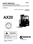
The finished thermometer requires only a single, unregulated
+12 V supply, and operates from -29°C to +60°C (-20°F to
+140°F).
The digital thermometer described here uses a ADD2500
2Y:z-digit DPM chip for A/D conversion and display decoding.
The LM 134 programmable current source operates here as the
temperature sensor, and the LM555 timer as a dc/dc converter.
The DS8866 and the pnp transistors drive the NSB3882
display.
Titled National Semiconductor Personal Communications:
CB Radio, the booklet is available without charge from
National Semiconductor Corp., 2900 Semiconductor Drive,
Santa Clara, Calif. 95051.
How To Build
A Digital Thermometer
The LM134 makes an excellent temperature sensor; it has a
constant temperat~re coefficient of +0.30%fC (O.167%fF);
and its noise immunity and current programmability make it
ideal for remote sensing use. Output-current flow through a
sense resistor scales the LM134's output voltage-in this case,
to 10 mV F, which is one count of the DPM or 1°F displayed.
Analog electronic thermometers have been available for some
time, but they are generally difficult to read and, besides, are
relatively fragile. Digital thermometers, on the other hand, are
both easy to read and rugged.
r
NSB3BB2
rf ~--.,.,
2) ." MATCH TEMPCO
02
03
1
G
od
1
X7
'1~
,.jJ
3) ALL OIOOES ARE lN914
41 TIE THE 'A' ANO '0' GROUNDS TOGETHER AT
ONE POINT ONL Y
li~
ff B
If "
lle!
1) A" RAOB·470N NETWORKS
A./-~G
'12 V
IN
OUT VCC
LM340T
2
3
.....-- 4
'5 V
-5.0
0.1
"F
1
MII
GN1
*0.01
J
II
II
2000 pF
1
BI-~
-=- r-~4
GNO
TI
510k,l%
.........
'Y"
H10.00 1
..... ,...
8
•
7
2.4k'
VCC
>
F
I
-::
RREF
E
VREF
0
0
0
.--
II
SCALE
'A' GNO
ZERO
g
A.
B
«
~
C
(l-
CIN
OP
r---
OPA
02
RE
2k
~
510k :
~
OPB
01
HI-
LM555CN
~
"A
•
10M
~III
~;:
......
,.....
....... -Vce
A
CMUX
03
~~
A
~,
-~
~
-::
.> 3.6k
LM134
ZERO .....
SENSOR ORANGE
I .....
j ::'J"~'
COMPUTE Newsletter. Vol. 3 No.6
C1 ~
~U
GREEN
2k
lOT
.).
~
lOOk
68"A
).
VIN
~.
....
........
1%
A
'Y
o GNO
.......
lk,.,:
•
2N4403
lOOk, lOT
-15v
J
~403
>~
..,-~ ~~'o
100"F
RAOB -200N
NC
0.0015 I
I-
fr<f
10
OSBB66N
).
~ G
" . 20k, lOT
G
TH
CREF
SCALE
,OIS ~
OUT
A f--
'1 F
--
0.1
rl-
A GNO
15
5
6
7
8
9
~
lEE
16 ___ 9
lB~
1
3.3k
L .........
SENSE RESISTOR
,.... ,.... .J:.
2N39~-.I
THERM
ZERO
).
>4~n
2N5457
~
470ln
-'e.".-
'Y""
~
NSL5053
~
5
Tough mathematical tasks are
child's play for Number Cruncher
New special-purpose microprocessor combines
best features of general-purpose and calculator chips
by Alan J. Weiss berger and Ted Toal, National Semiconductor Corp..
Reprinted from Electronics, February 17, 1977;
Copyright © McGraw-Hili, Inc., 1977
Santa Clara, Calif. •
oxide-semiconductor technology, can serve in machine
process controllers, navigation systems, and measurement and test equipment. It can also extend a mini- or
microcomputer's processing power when connected as a
peripheral device on the host processor's bus.
D There is one hurdle that the general-purpose microprocessor clears awkwardly: complex mathematical
computations. For such applications, designers have had
to spend considerable time learning to use efficiently the
chosen device's instruction set and unique input/output
transfer characteristics. Then they have had to sweat out
the development of complex software to perform the
desired mathematical operations or algorithms.
In such processing applications, software development
time can drop significantly with the NCU. Its instruction
set is like those of scientific calculators, which means
that the Number Cruncher already has most of the
required calculation software. Trigonometric, logarithmic, and exponential functions, for example, are
performed directly.
A few, hardy designers have put up with these chores
in order to gain the benefits of large-scale-integrated
technology, but even they would prefer a special-purpose
microprocessor designed specifically for complex calculations. A new microprocessor, the 57109 or Number
Crunching Unit, does this.
The NCU, presently being built with p-channel metal• AI Welssberger
Data formats at the input or the output may be in
floating-point or scientific notation. Digit lengths may
range up to an eight-digit mantissa, with one or two
digits for the exponent.
The 57109 combines the best features of calculator
is now with Signetics Corp., Sunnyvale, Calif.
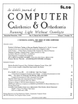
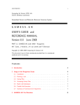
1. Digit handler. Major functional blocks of
the Number Cruncher are the control-logic
and arithmetic units and the programstorage ROM. which holds about 1,500 8-bit
microinstruction words. The device handles
4-bit binary-coded-decimal digits direclly.
They enter the control-logic block through
the I,. lines. and the results go out through
the digit-data-out block. The digit-addresscounter block sequences each digit during
input I output operations. Programmed instructions. 6 bits long. enter through the I, 6
lines and are converted to sequences of
microinstructions.
Vss ---..+9V
400-k Hz
OSCI LLATOR
CLOCK r+~t
GENER- f--+~2
ATOR f--+~3
f--+~4
(OSC -: 41
SYN CHRONIZAnON
POR
(POW ER-ON
RESE TI
16 /JC
IslAOR
~ HOLD
ROY
r- ISH
r- (INSTRUCTION SElECTI
..... CONTROL
SIGNALS r- RIW
r- OAS (DIGIT ADDRESS STROBEl
r- iiR (BRANCHI
ov
Voo -
J
I
} INTERNAL
--
(JUMP CONOITIONI
....
JJ
-
r-~
~
(ASYNCH RONOUS OATA REAOYI
CONTROL
LOGIC
14 /0 4
FLAGS
MICROPROGRAM'
STORAGE
ROM
~
INITIALIZATION
CLOCKS
~ ~~
} (USE R FLAGSI
r- ERROR
x
Y
Z
T
M
MEMORY
13/0 3
biD 2
1,/0 ,
!
ARITHMETIC
UNIT
DIGIT
~ ADDRESS
COUNTER
I
~
HIT DIGIT DATA
6
DIGIT
DATA
OUT
~ OA
DA3
~ DA4 -(MOST SIGNIFICANTI
DA, (LEAST SIGNIFICANT!
2
f::
r+
.......
DO, (lEAST SIGNIFICANT!
002
003
00 4 (MOST SIGNIFICANT!
COMPUTE Newsletter - Vol. 3 No.6
chips and general-purpose microprocessors (Table 1).
For example, its 1/0 functions are more flexible than
those of the calculator, which is limited to inputs from a
keyboard and ottt-puts to a display. But it is more directly
useful for calculations than microprocessors. The NCU
can accept a sequence of binary-coded-decimal digits
with a single input instruction, an asynchronous digit
input, or single-bit inputs for control purposes. In
contrast, microprocessors work only on data bytes.
TABLE 2 NCU INSTRUCTION CLASSES
Ditiulltty:
0-9
EE
CS
PI
EN
Unlike calculators, the Number Cruncher is controlled by a program stored in an external read-only
memory and can perform conditional and unconditional
program branches. As in processors, a HOLD input allows
handling asynchronous instructions and single stepping,
while test and branch instructions facilitate decisionmaking within programs.
X register.
Number entry terminatl!d and stack is pushed.
X-V-Z-T
Roll
Aoll stack. X - T - Z - V - X
Pop stack. X - V - Z ~ T - 0
Exchange X and Y. X -- Y
Exchange X with memory. X -- M
Memory store. X-M
Memory recall. X- M
POP
XEV
XEM
MS
MR
Math:
X - Y + X, X - Y - X
X- Y* X, X-Y+X
X-V'
M-M+X,M-M-X
M - M * X, M - M+ X
tIX,y'X, X2 tO', eX, Ifl I,.log X
Aesult in X, stack popped.
V-Z-T-O
Aesult in memory.
Aesult in X, previous X lost, stack
unchanged.
Aesult in X, previous X lost. stack
unchanged.
Convert X from radians to degrees or
vise versa. Previous X lost. stack unchanged.
SlN(X), COSiX). TAN/X)
SIN-'(X), COS-'(XI. TAN-'(X)
RTD,OTR
Output data passes through the digit-data-out block,
while the digit-address-counter block sequences each
digit during 1/0 operations. Logic levels are compatible
with low-power logic families, and the device has on-chip
generation of input/output strobes and timing signals.
Conditional-test-and-skip/branch instructions permit
decision making within the user's program. The conditional-test instructions operate on the results of computations or from an external jump-condition sense input
on line 16, The two flag outputs (F I and F 2) may be used
to activate external devices. A four-register stack (X, Y,
Z, T) holds operands and temporary results, and a
'If -+
Move:
The NCU'S major functional blocks (Fig. I) are the
control-logic and arithmetic units and the programstorage ROM, which holds about 1,500 8-bit microinstruction words. Programmed instructions, 6 bits long,
enter through the 11-6 lines and are converted to
sequences of microinstructions. Binary-coded-decimal
4-bit data words enter the control-logic block through
the 11_4 lines.
Examples of the 6-bit operation codes are given in
Table 2. (If 8-bit instruction memories are used, external
hardware can use the additional 2 bits for device
addresses.) Instruction executions vary in time from 1 to
500 milliseconds, although most require 5 to 10 ms.
Although these speeds may seem rather slow, they
compare favorably with similar functions implemented
as subroutines in low-cost microprocessors.
Each digit is entered into the X register mantissa
or exponent il in enter·exponent mode.
Fixes decimal point 01 mantissa 01 number
being entered.
Set enter·exponent mode.
Change sign 01 mantissa or exponent.
'r.nch:
JMP
Unconditional iump. On call branch instructions,
second word 01 instruction is the branch address,
which is loaded into an external program counter
by a load pulse from the NCU.
Test external iump condition, branch if true.
TJC
,
laputloutput:
IN
Multidigit synchronous input from AAM or
peripheral into X register.
Multidigit synchronous output to AAM or
peripheral from X register.
Single digit asynchronous input. Wait lor
asynchronous data ready (ADA! to go low, then
read data and pulse acknowledge flag F2
OUT
AIN
Mode control:
SMDC
Set mantissa digit count Irom one to eight digits.
FLOATING-POINT NOTATION
TAHL ~ 1 COMPARISON or LAR(,[ SCAI F INf'r,HI\HO
PROCESSING CHIPS
functioR
, Input/output
i
,
,
Number Cruncher
Microprocessor
multidigit,
asynchronous digit,
single bit
data bytes,
single bit
Data format
floatinwpoint or
scienti ic notation
floatin~-point
or
scienti ic notation
binary
Oatalength
fixed
variable (1 to 8
digits for mantissal
fixed
external ROM/program
counter. microprocessor,
or first-in, first-out
buffer memory
external ROM,
internal PC
14 - 400 ms
0.5 - 400 ms
0.5 - 500 ms
1- 3
1 (e~ternal PCI
2-6
I
,
Calculator
keyboard and
display
Program
fIleed (math or
I operations)
a
Minimum
number 01
: _chips lor CPU
key sequence
end RAM
COMPUTE Newsletter - VOl. 3 No.6
2
BIT 1 : SIGN OF
EXPONENT
BIT 4: SIGN OF
MANTISSA
DECIMAL
POINT
POSITION
D
4
MOSTSIG'
L.~_~_F~_~~_s~_l...l
N
lEASTSIG·
--- L.~_t_~~_~N_sl..J
3 .. N .. 10 (ONE TO EIGHT MANTISSA OIGITS!
SCIENTIFIC NOTATION
2
OF
MOST SIG· LEAST SIG· BIT t : SIGN
EXPONENT
NIFICANT NIFICANT
BIT
4:
SIGN
OF
EXPONENT EXPONENT
MANTISSA
4
~
U
5
N
MDSTSIG·
lEASTSIG
NIFICANT
MANTISSA
~t~~~~l
5 .. N .. 12 (ONE TO EIGHT MANTISSA DIGITS!
2. Two formata. The NCU can operate on data in floating-pOint or
scientific notation formats with one to eight mantissa digits.
depending on the setting of the digit count. It takes only one
instruction to input or output a string of digits.
7
JC ADR
COUNT
DSC
SYNC
0
74C157
QUAD 2:1
MULTI·
PLEXER
CLOCK LOAD CLEAR
IN
74C161
(2)
8·BIT
OUT
COUNTER
256'BY ·8·BI T
PROM
(8)
FLAG 1
ADDRESS
FLAG 2
(5203, 1702)
74C157
QUAD 2:1
MUX
A. - A,
Ao - AJ
O. - 0,
I. -I,
R/iiI
256·BH·BIT
RAM
INPUTS
OUTPUTS
3. ShInd-alone. The Number Cruncher can be used by itself in many control applications. Here a programmable ROM stores instructions,
controlled by an external program counter, and a 256-by-4-bit RAM extends the internal memory. Multiplexers enter data or instructions.
memory register can store constants or temporary results
or can serve as a loop counter for data transfer or
program control. Additional data storage may be
provided by external 256-word-by-4-bit random-access
memories.
The two data formats are shown in Fig. 2. No
reformatting is necessary when data is extracted from
the 57109 or reentered from an external RAM. An
asynchronous digit-input (AIN) instruction will accept a
single digit when a data-ready signal indicates valid
data.
Error detection is facilitated by an error flag, set by an
arithmetic or output error. The TERR instruction tests the
flag or can clear the external program counter, resulting
in a hardware jump to memory location 0, the error
recovery location. In either case, an ECLR instruction
must be executed to clear the error flag.
The ba.ic ••tup
The basic Number Cruncher system in Fig. 3 includes
a programmable ROM for instructions, an external
program counter, and a RAM for memory expansion. To
fetch an instruction from the PROM, the NCU raises its
ready line after it has executed the previous instruction.
This signal is used as a clock to advance the program
counter.
The PROM then accepts the new 8-bit address supplied
by the PC, executes a read cycle, and supplies the
instruction to the NCU. To facilitate entry of asynch8
ronous instructions, the 57109 does not lower ROY and
begin execution until its HOLD input is low.
When the incoming instruction is a test and skip, the
chip activates ROY to advance the PC and obtain the next
word on the PROM output lines. This word is actually a
branch address.
If the branch condition is true, the NCU'S branch
signal gates this address back to the program counter by
parallel-loading it on the leading edge of the next ROY
signal. When the PC is loaded, the PROM outputs will be
the contents of the instruction at the branch address.
If the branch condition is not true, ROY is raised to
step the PC so that it will point to the next sequential
instruction at the time of the next instruction fetch.
The instruction-select signal (ISEL) selects which type
of input will be used: instructions or data. The 2: 1
multiplexers supply the Number Cruncher with data
signals or instructions on the six input lines. This multiplexing saves pins so that the NCU can fit into a 28-pin
package.
For a data-input instruction (IN), the Number Cruncher again raises ROY to advance the PC to the next
instruction word, which contains a 4-bit high-order RAM
address. The NCU supplies a 4-bit low-order digit address
to the RAM from the digit-address DA lines and reads the
RAM digit data on its input lines, having set ISEL low to
select data instead of instructions. On a single IN instruction, 3 to 12 digits are input.
The OUT instruction procedure is similar to that for IN,
COMPUTE Newsletter. Vol. 3 No. 6
..
I--_ _ _;.:.;HO::.:L:.::.D..;..F:;;,L-A.:=\IG~_ _ _ _ _ _ _ _ _ _ _ _ _ _ _ _ _ _ _ _ ___t.~n.:::::: ~~
CONTROL
WRITE DATA SIGNAL
MICRO'
DATA
PROCESSOR --====~
BUS
t-ADDRESS
CONTROL
SYSTEM DATA BUS
.-----.r-;;;~--;-l
HOLO 1
HEX
LATCH OUT
(6)
..::=
(4)
QUAD
LATCH
OUT (TRI- IN
STATE)
DIGIT DATA
(4)
CLOCK ....._ _ _ _ _ _ _ _--,
EAOV
~
TO TRANSFER ON
NO
INSTR~CTION
PER!ORM
OTHER
PROCESSING
I
~NO
~J
1
t
RESET
I
CHIP SELECT
OUTRDY
FLIp·
FLOP
+-
RESET
I
:::
~~.~:
RDY
TRUE
YES~
0
SET
TRI~==I'OUT STATE
BU FFERS
(3)
OUTPUT
INSTRUCTION
TO S·SIT LATCH
,::,
CHIP SELECT
1+-----.....,
HOLO=O
INSTRUCTIONS
{} {}
(SUSPENO NCU AFTER
INSTRUCTION IS EXECUTED)
I
YES
CLOCK
1========;=:::;:==*====~>lIN
1/0 SELECT BUS
E?
=D--
Q
FLIPFLOP
I+-
..
::
,~ .~, .:
j,j....,. .
j~ :
,~.~
.
:.:
:~ :
....
~
,'...,' ,:
...
SET
NO
I
?
4. Pertners. The NCU can extend processing power of a general-purpose microprocessor by taking instructions and data from the
processor's bus and executing the instructions at its own pace. Flow chart shows software for microprocessor control of interlace.
except that digit-output data is supplied on the dataoutput DO lines and the read/write line is pulsed to
write each digit into the RAM. After putting out 3 to 12
digits, the 57109 enters a fetch cycle to obtain the next
instruction.
Extending 8 proce••or
Software overhead can be staggering for microprocessor applications requiring mathematical functions or
BCD operations. Sophisticated subroutines must be
written for multiply, divide, square root, log, exponential, and trigonometric functions. The data must be
scaled to fix the decimal-point position and to assure
there will be no register overflow as a result of an
operation. Further conversion is necessary if the result is
to be given in floating-point or scientific notation.
However, the Number Cruncher provides a microprocessor with a convenient peripheral unit for performing
these specialized calculations. The microprocessor
controls the NCU simply by supplying it with valid
instructions, directly or through a buffer memory. Overlapping execution in the two devices gives much greater
throughput than when the microprocessor performs the
calculations itself.
A straightforward processor-Ncu interface can be
built with a pair of latches (Fig. 4); one for instructions
and input data, the other for output data. The processor
suspends the NCU'S operation through the latter's HOLD
signal. When the microprocessor is ready, it loads the
COMPUTE Newsletter. Vol. 3 No.6
instruction latch with a 6-bit instruction code and sets
HOLD low.
The Number Cruncher executes the 6-bit code. The
microprocessor senses succeeding ROY signals from the
57109 (as an interrupt or jump-condition input) and
then loads the latch with the next instruction. It supplies
input data to the Number Cruncher on a digit-by-digit
basis in the same manner as it does 6-bit instructions.
When the NCU has data to send back, it uses a 4-bit
latch. The microprocessor reads and stores this data as it
is loaded into the latch.
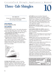
Using 8 FIFO
In another method for extending a microprocessor
system with the Number Cruncher, a first-in, first-out
buffer memory is a dynamic instruction store (Fig. 5).
The microprocessor loads the FIFO, and the NCU draws
instructions from it. Another FIFO is used for output data
from the 57109. Since these memories are totally
asynchronous, with separate input and output controls,
the processor and the Number Cruncher can run at full
speed in parallel for maximum system throughput.
This setup is useful in applications where the sequence
of instructions executed by the NCU may change. Since
the FIFO is a dynamic memory, it permits easy alteration
of the sequence. Because instructions are stored only
until the 57109 removes them, it is possible to load a
very large sequence in a very small space.
When the microprocessor has a job for the NCU, it
9
loads a linear sequence of instructions (no branches) into
the instruction FIFO, which was initially cleared. Once
loading has been completed, the processor is free to
process data or control devices. The FIFO can be used as
the storage medium for many different instruction
sequences with only minimum microprocessor software
required for loading.
data and gate it onto its instruction input lines.
The last instruction executed empties the FI FO, which
forces its output indicator to not ready. This flag is the
hold input for the NCU and an interrupt input for the
microprocessor, which senses that the Number Cruncher
has completed its instructions.
The 57109 continues to execute instructions until it
has completed its specialized calculations. It sends its
results to the output FIFO using an OUT instruction. If
output data is present in the FIFO, the processor senses
this via an interrupt or jump condition. It obtains the
results if needed or sends them on to an output device.
The FI FO stacks the instruction words in the same
order as they are entered and makes them available at
the output in the same sequence. The processor treats
instructions to the 57109 as output data, as if they were
to be written into a RAM or loaded into a register. But it
selects the FIFO as an 110 device by putting that
memory's address on its address bus. Next it puts the
NCU instruction data on the data bus followed by a write
strobe, which the FIFO uses as an input data clock.
Control by • ROM
To transfer instructions where only a few sequences
are necessary, a ROM can be programmed to contain the
sequence of instructions for the NCU. This setup is
similar to the stand-alone system in Fig. 3. It permits
conditional test instructions not possible with the FIFO
interface.
An AIN instruction suspends the Number Cruncher
until the microprocessor requests a calculation. At that
time the processor sets the asynchronous data ready
(ADR) to 0 and supplies a 4-bit starting address code.
The NCU decodes the starting address, branches to that
address in the ROM, and executes the calculation routine
there. As in the FIFO setup, an interrupt notifies the
microprocessor when the 57109 has completed its task.
In this setup, the microprocessor does not have to load
This sequence is repeated each time a word is loaded
into the FIFO. Before transmitting each instruction word,
the processor checks the FIFO'S status-indicator flag. If
the FIFO is full, the microprocessor waits until it is ready
before resuming data transfer.
While the processor is loading data into the FIFO, the
is fetching instructions from the FIFO output ports
at its own speed, executing them one by one. An outputindicator flag signals the 57109 when the ports are ready
(FIFO not empty) or not ready (FIFO empty). When the
processor has loaded the first instruction word, the FI FO
is ready and may be interrogated. The Number Cruncher'sready line is used as a FIFO output clock to extract
NCU
FIRST·1N,
FIRST·OUT
BUFFER
MEMORY
(INSTRUCTION)
DATA
DATA
BUS
CONTROLLER
"" j
IN
NCU
DATA
OUT
FIFO FULL
CONDITIONS
OR INPUTS
SYSTEM DATA BUS
,...
OUT
57109
NUMBER
CRUNCHER
NUMBER CRUNCHER
16 -1,
INSTRUCTIONS
WRITE
CLOCK
READ
CLOCK
ROY
INPUT·REAOY
OUTPUT·READY
1
FIFO EMPTY
HOLD
OUTPUT DATA READY
I
iOUTPUT·READY
MICRO'
PROCESSOR
8080
ADDRESS
6800
PACE
F·8
SC/MP
CDSMAC
CONTROL
I/O
CONTROL
LOGIC
FIFO READ
STROBE
,READ
CLOCK
WRITE
CLOCK
IN
OUT
RIW
RtW
DIGIT OUTPUT DATA
DO. - DO,
FIFO WRITE
STROBE
FIFO
(OUTPUTI
5, FIFO interface. A microprocessor can control the Number Cruncher through first-in first-out memories. The microprocessor enters data
and instructions into the instruction FIFO, and the Number Cruncher extracts them asynchronously.
10
COMPUTE Newsletter - Vol. 3 No.6
PROM INSTRUCTION STORE
(PROGRAM BITS) -
se
p.
P7
PO-PS
START CONVERSION
QUAO
2:1
MUX
A
Eoe
3-BCO
DIGIT
ANALOGI
OIGITAL
CONVERTER
ENO OF CONVERSION
(2)
OUT
OIGIT 1
A
QUAD
3:1
MULTIPLEXER
(4)
(4)
A
OUT
IN
OUT
CLOCK~----------------------~H---H--;+--'----------rr-'---------
SELECT tc::::;;====================~~==;::::~*==+::::::;-;::======~=+=ir===:::;:=
8-INPUT
ANALOG
MUX
(LATCHEO
CHANNEL
SELECT)
(4)
256-BY4-BIT
RAM
R/W
I.-I,
CHIP SE
t----------------'
1cC=====:::::=====:.J
(4)
.CY ....._ _ _
OUTPUTS
INSTRUCTION FORMAT
Type of instruction
P7
p.
Select analog channel
Analog-to-digital input
RAM 1/0
0
1
1
1
0
Others
1
1
1
Ps P4 P3 P2 P, Po
OUT instruction
AIN instruction
I NIOUT instructions for
fi rst word _Second word
PO- 3 are high-order
RAM address_
other instructions
CODING
P7
p.
1
1
1
LOOP 1
1
1
1
0
1
1
1
1
1
1
1
1
1
1
1
1
Ps-o
4
MS
SMDC1
MR
OUTO
PF1
EN
AIN (3)
DBl DONE
JMP LOOP
Comment
number of channels to be input
store in M
mantissa digit count = 1
retrieve channel number
select analog channel
start AID converter
push stack
read AID converter digits 1 to 3 when EOC = 0
update channel number and check
if 0
s. Dala acqui8ilion. The Number Cruncher can handle complex data in an analog system by controlling the analog multiplexer, which sends
analog data to an analog-to-digital converter_ The program listing shows how single instructions from the NCU handle complex operations_
a buffer memory to provide the NCU with instructions,
but merely switches it on by supplying a single input
(ADR). The result is very high system throughput and
parallel processing.
In the analog data-acquisition system in Fig. 6, the
PROM program controls the Number Cruncher. It makes
the NCU measure analog variables, perform some digital
transformation on them, compare the results to certain
specified limits, and send out control information on the
DO lines.
Acquiring analog data
An eight-input analog multiplexer selects the desired
analog input channel based on a 3-bit address supplied
by the NCU on DOl_I. This address is latched by the
multiplexer and will not change during the conversion
time of the three-BCD digit analog-to-digital converter
via Flag I. After starting the conversion via Flag I, the
NCU'S AIN instruction waits for the end-of-convert signal
before reading one of the three digits through the 3: 1
digital multiplexer. The second and third AIN instructions read the second and third BCD digits with the
results stored internally.
COMPUTE Newsletter. Vol. 3 No.6
The PROM program updates the analog address and
tests to see if all analog channels have been interrogated.
If so, the program will output the digitized data to the
RAM or will process the data as required. If not all analog
channels have been interrogated, the PROM program
scans the next one.
This system uses internal NCU storage for simultaneous calculations on four three-digit numbers. Additional storage is provided by the 256-by-4 RAM so that
the 57109 can operate on an array of data. Addressing
the data in the RAM is facilitated by the IN and OUT
instructions. The first instruction word is either IN or
OUT, and the second supplies a 5-bit address to select one
of 32 numbers in the RAM. This address is stable on the
instruction input lines (16-1) and is valid throughout the
data transfer cycle.
The Number Cruncher generates a 4-bit address
(DA 4_1) to select a digit each time it is ready to input or
output 4-bit data. For an OUT instruction, digit data is
output on D04_1 and clocked into the RAM by the R/W
strobe. For an IN instruction, the high level on R/W
causes the RAM to go into a read cycle and supply digit
data to the NCU through the quad 2: I multiplexers. 0
11
Dear COMPUTE:
the
[ffiJ 0
mQ0C5lli®G
Dear Georgia:
I recently noticed that you are providing a list of microprocessor consultants for your readers in each issue of
COMPUTE Newsletter. Please consider our corporation as
a possible addition to that list.
Texas Microsystems, Inc. is a Houston, Texas based consulting
firm started several years ago. In November of 1976, I left
National to open the West Coast Office of TM I. TM I has the
capability to provide complete microcomputer system design
and development, including hardware and software design.
We can handle the client's entire needs from evaluation and
specification to system prototype and debug. Our experience
ranges from IMP-16, PACE and SC/MP systems, to systems
involving the 8080A, 8085 and 8048, as well as other
microprocessors.
Before November 1976, I spent three years as a microprocessor
systems design engineer with National, working on such
projects, as the PACE/16-P interface card, PACE application
cards, PACE lCDS and custom SCMP microcomputer systems. I am currently a member of COMPUTE.
Thanks for considering Texas Microsystems, Inc.
Sincerely,
TEXAS MICROSYSTEMS, INC.
GARY A. MillER
Regional Director
West Coast Office
1530 The Alameda
Suite 200
San Jose, CA 95126
(408) 292-4004
The next time you list microprocessor consultants please add
us to your list. We are presently working with several of the
popular 8-bit processors as well as with IMP.
Thank you,
Ron Tipton, President
TDl Electronics
Route 7
Fayetteville, Arkansas 72701
(501) 643-2191
Done.
Dear Ms. Marszalek:
Since I wrote you last week about the problems with the
SC/MP Cassette system, I discovered a potential problem
with the software in the SC/MP keyboard kit SKMPKB. It
contains a re-executable subroutine KYBD at location
X'0185 which can be used by other software for display
and keyboard input. It should be pointed out to users of
this subroutine that the Carry/Link (CY /l) flag must be
reset (cleared, CCl instruction) prior to calling KYBD.
If CY /l is set, the number returned in the E register will be
incorrect for keyboard keys 8 thru F.
Is it possible to obtain a corrected copy of the SC/MP Keyboard Kit Schematic Diagram (Drawing NS10634) which
is in the Keyboard Kit User's Manual? The one in my manual
contains a large number of errors.
The SC/MP Cassette continues to work well - zero errors
after many 1 k byte reads and writes.
Sincerely,
Ronald G. Parsons
9001 laurel Grove Drive
Austin, Texas 78758
Drawing NS10634 is replaced by NS10586 (shown on page 13
this issue) in revision B of SC/MP Keyboard Kit User's Manual.
Sir,
Dear Georgia:
My SC/MP based microcomputer is up and running. I built it
for under $100with 1K of RAM (2102's) yet!
On page 5-3 of the technical description I read of a user group
and imagine you have information to share about using this
CPU chip.
Please add me to the club. My particular interest is circuits
showing how to expand my unit to TV, keyboard and cassette.
I have built a Homebrew SC/MP, with 1 K of 1702A, 1 K of
2102L1, ASCII Keyboard, and selectric printing unit. I've
implemented the hold and continue control lines and have a
full front-panel lED display of addresses, data (read or write).
and all flags and status indicators. I need some programming
hints on subroutine linkage, etc.
Thanks,
Sincerely,
Olin R. Boyer
P.O. Box 3000
Tulsa, OK 74102
Bob Weir
318 N. 7th
Canon City, CO 81212
See the SC/MP Programming and Assembler Manual Chap. 6
for some programming details. Also the SC/MP Applications
Handbook has many programming examples.
Any help at all is OK and let me know how I can aid you too.
12
COMPUTE Newsletter. Vol. 3 No.6
"V
-..--.---.r-->
~5K
..
l
:
4
" "'D~8,--""""HI------,~.
14
~l-"=-------""
0.........-;._
"K
DBI
,
E-----<HI-----~
"i-=D=B3_ _ _--<~-----':::.j3 3D
~
Ie ,)-=.:.....-_-,
r--_~21DM7'LS1&n ~ t-+-+--4'-L..~J
~ ~r:I"";'sr"l
~~
~
....!!
SC/M!' KIT
OA
I
SCIM'INTAOK.T
NWOS
1
+----"":..r--.... "
~.
12
DM74LIIN
l:i\'3C""'I.~"·"~
fi\..'!lJ
13
IE"
~'c:...'_ _ _---4
12
DB.
11
DBS
10
08&
B
'URGe
c
~~'-------~~~--------4
--'
~&DM1<ICIIN
'ZiRG IE
I"33SEGF
P21SlGG
.In)
'D
~ OM7'LS1S1
~r~
A
mSEGB
'31 SEG D
3,.....~.
I.
I'3IISEGA
Ie
D
E
F
G
• -----
"r'~Ir+~_~1O~_1EJJr'----J
'y
12
3B
~---~-----~.
I-"=-----+---_--'J~
10
11
9
DISPLAY
,
1.2.16
INIT
I - - - - ~~~:..MY
L _ _ __ ~~~2~:IS
AEFEA TO FlGUAE.
~~~~I~-:~gR
Z-2
SC/MP INTROKIT
:=!:~~c
Ie
"ESPEeTlYEL Y. : .
rA""OO,------="-\,':;.;;
'r'_4L-,
AD10
5
JJ 3C
OM74LI&N
..>.(J)..!./L.::./
-!1~
RlSET*
TOJ'
I
......J
"1,
lD
Upon receipt of the unit in the service center the technician
will determine if the kit will be repaired under warranty or if
the customer is responsible for its repair.
If the customer is found to be responsible, a charge of $35.00
per hour plus parts will be charged. A purchase order or check
for the amount of the repairs must be sent to the service center
prior to the return of the repaired kit.
COMPUTE Newsletter. Vol. 3 No.6
OFF
<n---.c' ........
1'--. iNiUtId_
.......... 1
RESET·~
GNO~\
ON
1
Name of customer contact
Telephone number of contact
Data purchased
Purchased from
Symptom of problem
NATIONAL SEMICONDUCTOR CORP.
2921 COPPER RD.
SANTA CLARA, CA. 95051
ATTN: MICROCOMPUTER SERVICE CENTER
...
,
5.11t
Kits may be returned to the Microcomputer Service Center for
repair on a consignment basis only! NO DEBIT MEMO'S. The
customer should return the kit, not the distributor. The following information MUST be supplied or kit will be returned.
Kits must be returned to:
,.,
~1
IFIGURE22~2
"V
SC/MP KEYBOARD KIT REPAm POLICY
1)
2)
3)
4)
5)
NOlIE:
SWITCH
-,
The following spare parts are also available from the service
center. A check payable to National Semiconductor must
accompany all orders.
P/N482305235 - 001 KEYBOARD KIT ROM @ $25.00
P/N980305232 - 001 KEYBOARD & CABLE @ $35.00
National CSS has extended its telephone access and service
through the world-wide TELEX network. This enables customers to access any of our host machines by dialing the NeSS
TELEX rotor, 965806. International users may also access
TWX by dialing 710-474-3540.
Line charges to the customer will be from the originating
country to Stamford, Conn. All TELEX users should type
(L TRS) NCSS after the connect light illuminates. Any problem during login should be reported to NCSS at (203) 327-9100
extension 381.
NATIONAL CSS,INC.
542 Westport Avenue
Norwalk, Connecticut 06851
(203) 853-7200
13
UNDERGROUND BUYING GUIDE
TELLS ELECTRONIC HOBBYISTS
WHERE TO GET IT
A new directory has just been published that helps amateurs,
CBers, experimenters and computer hobbyists locate equipment, parts, supplies and services.
Over 600 sources of standard and hard-to-find gear are listed
in the handy guide. Many of the 600 sources are mail order
firms and discounters. All are firms that do business with
electronic hobbyists.
The Underground Buying Guide is available direct mail from
PMS Publishing, 12625 Lido Way, Saratoga, CA. 95070.
The price is $5.95 plus 55(/! postage and handling.
Californians add 39(/! sales tax.
For further information contact:
Dennis A. King
PMS Publishing
12625 Lido Way
Saratoga, CA. 95070
(408) 996-0471
MICROPROC€~~OR U~€R'~
GROUP
SL0042A
IMP-16
SM/PL
SM/PL is a high level programming language compiler
for the IMP-16. See Compute
Vol. 2, #8 for language features. It requires 16K of R/W
memory and can be used with
the IMP-16 disc system. Cost
is $100.00 for the manual,
object module paper tape and
source listing.
SL0043A
SC/MP
NIBL
Instructions and listing for
conversion of DATA
GENERAL's Nova Assembler
to a PACE cross assembler.
Limited copies available.
NIB L is a version of Ti ny Basic
for SC/MP. It requires 4K of
memory for the interpreter
and an additional 2-4K for
the NIBL source program.
Cost is $15.00 for the paper
tape load module and source
listing. Both p- and n-channel
versions are available.
SL0045A
PDP-15
PACE
X-Assembler
8080 Cross Assembler for
IMP-16. Object Module and
source listing only available
$15.00. Uses assembly
directives similar to other
National assemblers.
FORTRAN cross-assembler
with modified mnemonics.
Reference: BYTE May 1976,
"Simplifying Your Homemade Assembler" by Greg
Jewell.
SL046A
PDP-8
SC/MP-Basic
X-Assembler
Cross-assembler written in
BASIC for PDP-BE with disc
operating system. Listing
only available. Contributed
by R. Gitzel, University of
Alberta, Edmonton, Canada.
The following programs are available from the COMPUTE User
Group Library. Copies can be ordered from COMPUTE/208,
National Semiconductor, 2900 Semiconductor Drive, Santa
Clara, Ca. 95051.
These programs are versions of assemblers, interpreters or
compilers available for IMP, PACE, and SC/MP. Included in
this list is also a listing of modifications for the NOVA
assembler that will allow it to produce PACE object code
and a PACE assembler written in FORTRAN with modified
assembly mnemonics.
Note: As part of the User Library, these programs are not
supported as National products.
Program
Number
Program
Name
SL0034A
NOVA
SL0040A
IMP-16
8080X
Description
Requires the following definitions: B=O, C=1, 0=2, E=3,
H=4, L=5, A=7, memory=6,
PSW=6, Stack Pointer=7.
14
COMPUTE Newsletter. Vol. 3 No.6
USERS LIBRARY ORDER FORM
PROGRAM
NUMBER
NAME
NUMBER
OF
PROGRAM
LISTINGS
IMP PROGRAMS
SL001A
BINBCD
SL002A
BCD
SL003A
MD
PTBIN
SL004A
SL005A
BINASC
SL006A
BINGRAY
SL007B
BCDBIN
SL008A
PNMULT
SL010A
MEMORY DUMP
SL011A
GALPAT
RAMDUMP
SL012B
SL013A
TAPE TITLER
SL014A
GRAY CODE
SL016A
PRTPLT
SL017A
TSTPLT
SL019A
MESGH
SL020A
CHARST
SL021A
CONTAP
SL023A
DISC RLMPROMSFT-B
DISC RLMSL024A
PROMSFT-C
TABTAP
SL026A
SORT
SL028A
TITLER
SL030A
SL031A
DORG
TAPE
SL038A
SL040A
8080-X
SL042A
SM/PL
SL044A
DECIM8
SOURCE PAPER
TAPES
UNIT
COST
QUANTITY
TOTAL
COST
NA
NA
NA
NA
NA
NA
NA
NA
$5.00
$5.00
$5.00
$5.00
$5.00
$5.00
$5.00
$5.00
$5.00
$5.00
$$-$$_$-$-$$$-$-
$5.00
$-
$5.00
$5.00
$15.00
$100.00
$5.00
$-$$-$$--
$5.00
$5.00
$5.00
$5.00
$5.00
$-$-$$$--
$5.00
$5.00
$5.00
$5.00
$-$-$_$_-
$5.00
$5.00
$5.00
$15.00
$5.00
$-$-$-$-$_-
$5.00
$--
NA
NA
NA
NA
*
*t
PACE PROGRAMS
PACRAM
SL015A
SL018A
CALCULATOR
NUMPRG
SL022A
PALM
SL025A
SL026A
TABTAP
BINBCD
SL029A
SL032A
DIVIDE
SL033A
DELSEM
PRNTLM
SL035A
SL036A
BASCI!
SL037A
JITTER
NA
NA
SC/MP PROGRAMS
SC/MP MATH
SL027B
SL039A
TAPEI/O
SL041A
SCSORT
SL043A
NIBL
SL047A
PLOT
*
NOVA PROGRAMS
SL034A
PACE-X
NA
PDP-15 PROGRAMS
PACE-X
SL045A
PDP-8 PROGRAMS
SL046A
SC/MP-X
NA
TOTAL
$
*Price includes the manual, program listing, and paper tape load module.
tAvailable from the Melbourne Training Centre in Australia for DLR 100.00 for SM/PL and DLR 15.00 for NIBL.
Please make sure the programs you select are for the microprocessor you have.
Notes: 1. There is no charge for program listings, but the number of listings per order is limited to three (31.
NAME _______________________
TITLE ______________________
COMPANY __________________
ADDRESS ___________________
CITY ______________________
COMPUTE Newsletter. Vol. 3 No.6
Fill out the form completely,
UNITED STATES
COMPUTE/208
National Semiconductor
2900 Semiconductor Drive
Santa Clara, CA 95051
(4081247-7924
2. NA indicates not available.
make your check payable to COMPUTE, and mail to:
GERMANY
AUSTRALIA
National Semiconductor GmBH NS Electronics Pty Ltd.
808 Fuerstenfeldbruck
Cnr. Stud Road & Mtn. Highway
Industriestrasse 10
Bayswater, Victoria 3153
Tel:08141/1371
Tel: 03·729-6333
Telex: 05-27649
Telex: 32096
15
BULK RATE
U.S. POSTAGE
PAID
PERMIT NO. 317
SUNNYVALE, CALIF
CALL FOR PAPERS
IECI 78 CONFERENCE
"INDUSTRIAL APPLICATIONS OF MICROPROCESSORS"
SHERATON HOTEL
•
Philadelphia, Pennsylvania
•
MARCH 20-22, 1978
Papers on the Following Subjects are Invited:
•
•
•
•
•
•
•
•
•
•
Industrial Uses of Microprocessors
Microprocessor System Hardware Architecture
Microprocessor Software and Standardization
Microprocessor in Thyristor Controls
Computerized Data Acquisition Systems
Programmable Controllers
MSI and LSI in Process Control
Automotive Diagnosis and Operation
Vehicle Control
Automatic Inspection
• "Intelligent" Test Instrumentation
• Transducers
• Textile Manufacturing
• Food Processing
• Petroleum Refining
• Geophysics
• Metal Fabrication
• Power Generation
• Education
• The State-of-the-Art in Microprocessor Standards.
PAPER REQUIREMENTS
Ten copies of the paper in summary form no longer than 600 words and an abstract of no more than 60 words, describing
work not generally published or previously presented. The copies should be mailed by August 25, 1977 to:
H. W. MERGLER
Leonard Case Professor of Electrical Engineering
CASE WESTERN RESERVE UNIVERSITY
CLEVELAND, OHIO 44106
216/368-4574
The paper summary will be used for paper selection and session assignment and thus should clearly define the salient concepts
and NOVEL features of the work described.
Notification of acceptance and format required for publication in the IECI '77 Proceedings will be sent to you by September 25,1977. Final manuscripts of papers accepted for publication in the IECI proceedings must be received by
November 25, 1977.
UNITED STATES
GERMANY
AUSTRALIA
COMPUTE/208
National Semiconductor
2900 Semiconductor Dr.
Santa Clara, CA 95051
Tel: (408) 247-7924
TWX: 910-338-0537
National Semiconductor Corp. Gmbh
808 Fuerstenfeldbruck
I ndustriestrasse 10
Tel: 08141/1371
Telex: 05-27649
NS Electronics Pty Ltd.
Cnr. Stud Road & Mtn. Highway
Bayswater, Victoria 3153
Tel: 03-729-6333
Telex: 32096
16
COMPUTE Newsletter. Vol. 3 No.6