1
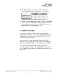
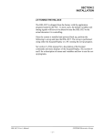
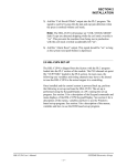
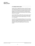
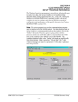
SECTION 2
INSTALLATION
_______________________________________________________________________________
2.10 TUNING THE HSL-CD4
The HSL-CD4 is shipped from the factory with the PLC application program loaded in the M4500
module (PLC section) and the PLS channel set-point file "CD4TMG" loaded in the PLS section.
These standard programs are used to implement the decorator or basecoater algorithms. In most
cases, the following user variables and timing signals may have to be altered to tune the HSL-CD4
to the actual decorator it is controlling.
Once the system is installed and powered back up, perform the following to set-up and tune the
HSL-CD4. The set-up is performed using either the Keypad/Display or a PC running the set-up
program.
See the HSM-CD4/CD7 Keypad Quick Reference for key depress sequences for entering the
following parameters. See section 3 of this manual for a description of the Keypad commands and
menu displays of the Keypad/Display. See sections 4 and 5 for a description of menus and variables
and how to use the set-up programs.
_______________________________________________________________________________
2.10.1 DEFAULT SET-UP VARIABLES
As shipped, the user variables for the M4500 are set to the following defaults:
Print Carriage and Varnish Unit:
Print Carriage retract response time (msec)
Print Carriage extend response time (msec)
Varnish Unit retract response time (msec)
Varnish Unit extend response time (msec)
Number of Shifts to Varnish Unit
: 45
: 45
: 60
: 60
:5
Bad Can (pin chain) Blow-off:
# of cans to blow-off from infeed open
# of cans to blow-off from print at restart
# of cans to blow-off from varnish at restart
# of cans to blow-off for each misload
# of pins to pin chain blow-off port
# of cans from infeed to can PRX
Blow-off solenoid "on" response time (msec)
Blow-off solenoid "off" response time (msec)
:6
:4
:4
:3
: 50
:6
: 15
: 20
QC Can (select-a-can) Blow-off:
Blow-off solenoid "on" response time (msec)
Blow-off solenoid "off" response time (msec)
QC can blow-off port shift offset
Blanket wheel segments
: 15
: 20
:1
:8
Spindle Trip Offset
:0
HSL-CD4 User’s Manual
SYSTEMS Electronics Group
- 14 -
SECTION 2
INSTALLATION
The "CD4TMG" timing channel file, as shipped, contains the following default timing set-points:
CHAN
ON - OFF
DESCRIPTION
CH00:
CH01:
CH02:
CH03:
CH04:
CH05:
CH06:
CH07:
CH10:
CH11:
CH12:
CH13:
CH14:
CH15:
CH16:
CH17:
020
010
180
060
030
250
255
000
000
___
___
___
___
___
___
___
Carriage trip timing
Varnish trip timing
Can/No Can clock
Damaged Can Blow-off (Low speed)
Damaged Can Blow-off (High speed)
Pin Chain Blow-off (bad can) timing
Select-A-Can (QC) Blow-off timing
Can Gate Timing
PLC Clock Timing
-
060
050
000
250
200
290
295
140
180
___
___
___
___
___
___
___
HSL-CD4 User’s Manual
SYSTEMS Electronics Group
- 15 -
SECTION 2
INSTALLATION
________________________________________________________________________________
2.10.2 SET MACHINE ZERO
1) Position the machine at machine zero.
Machine Zero Position
(as seen from back of machine)
2) Set the resolver offset. Using the Keypad/Display, perform the following:
a) Press the “Set-Up” key.
b) Press the #5 key – Zero Machine (set resolver offset).
c) Enter “0” to zero the resolver and set the offset. The timing channel set-up menu will be
displayed, showing the position, “POS:”, at zero.
HSL-CD4 User’s Manual
SYSTEMS Electronics Group
- 16 -
SECTION 2
INSTALLATION
________________________________________________________________________________
2.10.3 VERIFY LOCATION OF CAN/NO CAN SENSOR
Verify that the location of the can/no can sensor is at the 2nd spindle from 12 o'clock when the
machine is at zero.
Location of Can/No Can Sensor
Verify the location of the Can/No Can sensor. Place a can on a spindle and slowly jog it past the
sensor. The sensor should first see the can at between 300 and 0 degrees. If it does, the location of
the sensor is correct.
Note: The Can/No Can sensor “ON” position can be viewed by selecting option #6 – View Critical
Input Positions, from the primary setup menu using the Keypad/Display.
If the sensor first sees the can between 0 and 30 degrees, the system will still function correctly but
the Damaged Can Blow-off (HI - CH04) and (LOW - CH03) timing signals may have to be
adjusted. If the Can/No Can sensor first sees the can outside the 300 to 30 degree range, the sensor
should be moved to within the 300 to 0 degree range.
HSL-CD4 User’s Manual
SYSTEMS Electronics Group
- 17 -
SECTION 2
INSTALLATION
________________________________________________________________________________
2.10.4 SET PIN CHAIN BLOW-OFF TIMING
1) Set the bad can (pin chain) blow-off timing (CH05) such that the timing signal just turns “ON”
when the pin chain blow-off port is centered between pins.
Location of Blow-off Timing “ON” Position
(channel 05 or 06)
2) From the primary setup menu using the Keypad/Display, select option #3 – Set Machine Timing
(set-points, etc.) and perform the following:
a) With the machine stopped, view the resolver position.
b) Select timing channel CH05 – Pin Chain Blow-off.
c) Clear the channel (press the “CLEAR CHAN” key).
d) Enter a new set-point (press the “ENTER SET-POINT” key). The “ON” SETPOINT should
be the current position of the resolver (press the “ENTER” key). The “OFF” SETPOINT
should be set 40 degrees after the “ON” set-point (press the “ENTER” key).
e) Search the channel to confirm only one set-point (one on setting and one off setting).
HSL-CD4 User’s Manual
SYSTEMS Electronics Group
- 18 -
SECTION 2
INSTALLATION
________________________________________________________________________________
2.10.5 SET # OF PINS TO PIN CHAIN BLOW-OFF PORT
Perform the following to set the "# of pins to pin chain blow-off port":
Note: That the chain take-up must be after the bad can pin chain blow-off port for reliable pin
chain blow-off. If the take-up is before the port, the relative position of the port to the blow-off
timing will vary as the take-up moves, causing partial blow-offs to occur.
1) Count the number of pins from the spindle wheel to disc transfer location to the bad can pin
chain blow-off port
2) From the primary setup menu using the Keypad/Display, select option #2 – Set Pin Chain/QC
Blow-off Parameters. Press the “NEXT” key until “# PINS TO PIN CHAIN BLOW-OFF
PORT:” is displayed.
3) The number entered is the number counted minus 2 (this is still just an approximation).
4) Set the "# CANS TO BLOW-OFF FOR EACH MISLOAD" (press the “PREV” key) equal to
five.
5) Run the machine at low speed. Open the infeed and allow cans to load and be printed. After
cans have passed the pin chain blow-off port, close the infeed and observe the number of cans
blown off.
Note: Half prints or silver cans may get through the line until this variable is set-up properly.
Adjust the number of pins to pin chain blow-off such that whenever the infeed is closed, one
(half printed) can is consistently blown off.
If no cans are blown off, the number of pins to pin chain blow-off is too high (blow-off comes
on too late). Reduce the number of pins to pin chain blow-off and repeat this step again.
If more than one can is blown off, the number of pins is too low (blow-off comes on too early).
Increase the number of pins to pin chain blow-off and repeat this step again.
6) Set the "# CANS TO BLOW-OFF FOR EACH MISLOAD" equal to 3.Run the machine at low
speed with cans and verify that for each miss-loaded can, three bad cans are blown off (missloaded silver can blown off at damaged can blow-off port, half print cans ahead and behind
miss-loaded can blown off at pin chain port). If not adjust "# of pins to pin chain blow-off port"
accordingly until they are.
HSL-CD4 User’s Manual
SYSTEMS Electronics Group
- 19 -
SECTION 2
INSTALLATION
Note: Once this variable is set, it may be desirable to set the "# of cans to blow-off for each
misload" equal to 4 or 5 until the print carriage and varnish unit response times are set in steps 5
and 6. This is done so that the cans following the miss-load can be verified for proper print. Once
this is done, the "# of cans to blow-off for each misload" can be set back to 3.
________________________________________________________________________________
2.10.6 SET # OF CANS TO BLOW-OFF AT RESTART
From the primary setup menu using the Keypad/Display, select option #2 – Set Pin Chain/QC
Blow-off Parameters. Set the following infeed open/restart blow-off parameters (as desired):
a) "# of Cans to Blow-off at Infeed Open"
b) "# of Cans to Blow-off from Print at Restart"
c) "# of Cans to Blow-off from Varnish at Restart”
________________________________________________________________________________
2.10.7 SET # OF CANS FROM INFEED TO CAN PRX
This parameter is used to adjust the number of stations from the can gate solenoid to can/no can
sensor. Default value is set to 6 stations. Some Rutherford decorators utilize an infeed star wheel,
adding an additional 6 (total 12) stations from infeed to can PRX.
Perform the following to set the "# of Cans from Infeed to Can PRX":
1) From the primary setup menu using the Keypad/Display, select option #2 – Set Pin Chain/QC
Blow-off Parameters. Press the “NEXT” key until “# OF CANS FROM INFEED TO CAN
PRX:” is displayed.
2) Initially set this value to 6. If an infeed star wheel is used, set this value to 12.
3) Run the machine at low speed. Open the infeed and allow cans to load and be printed. From
the default display of the Keypad/Display, observe the “BLOWOFFS” field. At “Infeed Open”
this number should increment up by the number of cans to blow-off at infeed open. Observe
that this same number of cans are blown off at the bad can pin chain blow-off port.
4) If the number of cans blown off was less than the number counted, increase the number of cans
from infeed to can PRX by the difference.
5) If the number of cans blown off was more than the number counted, decrease the number of
cans from infeed to can PRX by the difference.
HSL-CD4 User’s Manual
SYSTEMS Electronics Group
- 20 -
SECTION 2
INSTALLATION
6) Continue to adjust this parameter until the actual number of cans blown off at infeed open is
equal to the desired.
________________________________________________________________________________
2.10.8 SET PRINT CARRIAGE AND VARNISH UNIT "RETRACT"/"EXTEND"
RESPONSE TIMES
The retract and extend response times is the amount of time the control system will lead the trip
point (CH00 for the print carriage, CH01 for the varnish unit) to compensate for the mechanical
response time of the machine. To verify the print carriage and varnish unit trip control, run the
machine at high speed, induce miss-loads and observe the cans blown off at the pin chain blow-off.
Note: Pressing the “Blank Key” on the Keypad/Display while the default display is shown will
electronically induce a misload into the system.
The miss-loaded can should be completely silver. The can ahead of the miss-load (can the carriage
retracted on) should be blown off at the pin chain blow off port and should be 1/4 to 1/2 printed.
The can behind the miss-load (the can the carriage extended on) should be blown off at the pin
chain blow off port and should be 1/2 to 3/4 printed. Any additional cans blown off following the
half print behind the miss-load should be fully printed and of good quality print.
From the primary setup menu using the Keypad/Display, select option #1 – Set Carriage/Varnish
Response Times.
If the can ahead of the miss-load (carriage retracted on) is fully printed or more than half printed,
the "Print Carriage retract (out) response time" is too short and the carriage is not retracting soon
enough. Increase the "Print Carriage retract (out) response time" by 5 milliseconds and try again.
Continue increasing this time until this can is 1/4 to 1/2 printed. If this can is less than 1/4 printed or
silver, the "Print Carriage retract (out) response time" is too long and the carriage is retracting too
soon. Decrease the "Print Carriage retract (out) response time" by 5 milliseconds and try again.
Continue decreasing this time until this can is 1/4 to 1/2 printed (press the “NEXT” key).
If the can behind the miss-load (carriage extended on) is less than 1/2 printed or silver, the "Print
Carriage extend (in) response time" is too short and the carriage is not extending soon enough.
Increase the "Print Carriage extend (in) response time" by 5 milliseconds and try again. Continue
increasing this time until this can is 1/2 to 3/4 printed. If this can is more than 3/4 printed or fully
printed, the "Print Carriage extend (in) response time" is too long and the carriage is extending too
soon. Decrease the "Print Carriage extend (in) response time" by 5 milliseconds and try again.
Continue decreasing this time until this can is 1/2 to 3/4 printed.
Note: The "extend (in)" time is a function of the "retract (out)" time. Therefore the "retract (out)"
time should always be set as desired first, before setting the "extend (in)" time.
HSL-CD4 User’s Manual
SYSTEMS Electronics Group
- 21 -
SECTION 2
INSTALLATION
Prior to setting the varnish unit retract/extend response times, set the number of shifts to the varnish
unit. For older generation Rutherford Decorators, this is set to "5". For newer decorators, this is set
to "4". In general, this is set such that the varnish unit retracts out on the can ahead of the misloaded
spindle.
Set the varnish extend and retract response times in the same fashion as was done for the carriage.
In general, the miss-loaded can should have no varnish on it, the can ahead and behind should be
approximately 2/3 varnished.
________________________________________________________________________________
2.10.9 SET QC BLOW-OFF SHIFT OFFSET
If the QC Can (select-a-can) feature is used, set the "QC can blow-off port shift offset" as follows:
1) Dial in spindle #1 on the Select-A-Can thumbwheel switch. This function can also be
performed from the Keypad/Display utilizing the “QC BLOW-OFF” key and entering “1”.
2) With the machine running slowly, mark cans printed on spindle #1 so they can be identified
while on the pin chain.
3) Press the Select-A-Can pushbutton and compare the can that was actually blown off with the
location of a can marked on spindle #1.
4) From the primary setup menu using the Keypad/Display, select option #2 – Set Pin Chain/QC
Blow-off Parameters. Press the “NEXT” key until “# QC BLOW-OFF SHIFT OFFSET (124):” is displayed. Add the difference between the can actually blown off and the marked can
on spindle #1 to the QC blow-off shift offset and enter this as the new offset number.
5) Continue to adjust the offset number until a can marked on spindle #1 is blown off.
Note: This variable must be a number between 1 and 24 as there is always a can printed on spindle
#1 every 24 cans.
HSL-CD4 User’s Manual
SYSTEMS Electronics Group
- 22 -
SECTION 2
INSTALLATION
________________________________________________________________________________
2.10.10 SET BLANKET WHEEL SEGMENTS
The blanket wheel segments is the value used to blow-off a consecutive number of cans (starting
with blanket #1) whenever a “Blanket” QC Blow-off is initiated (QC blow-off code #25).
Set the number of “Blanket Wheel Segments” as follows:
1) From the primary setup menu using the Keypad/Display, select option #2 – Set Pin Chain/QC
Blow-off Parameters. Press the “NEXT” key until “BLANKET WHEEL SEGMENTS (4-12):”
is displayed (last setup parameter in this menu).
2) Enter the number of segments on the blanket wheel.
________________________________________________________________________________
2.10.11 SET SPINDLE TRIP SHIFT OFFSET
Set the "Spindle Trip Shift Offset" as follows:
1) From the primary setup menu using the Keypad/Display, select option #2 – Set Pin Chain/QC
Blow-off Parameters. Press the “NEXT” key until “SPINDLE TRIP SHIFT OFFSET (0-23):”
is displayed (last setup parameter in this menu).
2) Initially set the "Spindle Trip Offset" to zero.
3) Wrap a piece of tape around spindle #1 such that cans will not load on this spindle. With the
machine running slowly open the can gate and verify that cans do not load on spindle #1 and
that the print carriage is tripped for that spindle.
4) Observe the “Trips per Spindle” data and determine which spindle number is being
incremented. The spindle number that should be incrementing is spindle #1. If it is not, subtract
1 from the spindle number that is being incremented and enter this value as the “Spindle Trip
Shift Offset”.
5) Verify that the spindle #1 count is incremented every time the carriage trips for spindle #1. If it
still increments another spindle number, continue adjusting the "Spindle Trip Shift Offset" until
it does. Stop the machine and remove the tape from spindle #1. The machine is now set-up and
ready to run.
HSL-CD4 User’s Manual
SYSTEMS Electronics Group
- 23 -