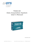
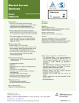
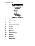
1
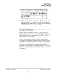
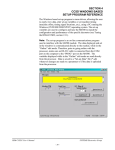
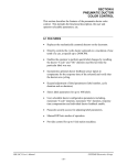
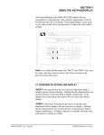
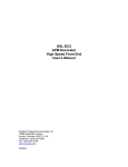
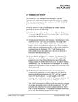
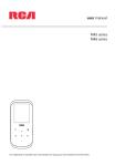
SECTION 2
INSTALLATION
________________________________________________________
2.9 TUNING THE HSL-DC5
The HSL-DC5 is shipped from the factory with the application
program loaded in the PLC. In most cases, the default variables and
timing signals will have to be altered to tune the HSL-DC5 to the
actual decorator it is controlling.
Once the system is installed and powered back up, perform the
following to set-up and tune the HSL-DC5. The set-up is performed
using either the Keypad/Display or a PC running the set-up program.
See section 3 of this manual for a description of the Keypad
commands and menu displays of the Keypad/Display. See sections 4
and 5 for a description of menus and variables and how to use the setup programs.
HSL-DC5 User’s Manual
SYSTEMS Electronics Group
- 17 -
SECTION 2
INSTALLATION
________________________________________________________
2.9.1 DEFAULT SET-UP VARIABLES
As shipped, the user variables for the M4508 are set the following
defaults:
Speed Parameters:
Canfeed Enable - Low Speed
Canfeed Enable - High Speed
O’Varnish Roll Speed Calibrate
: 600
: 1000
: 380
Pneumatic Ductor Parameters:
: 500
Maximum Cycle Duration (0.1 cans)
Maximum “On” Duration (0.1 cans)
: 200
Response Time Compensation (msec)
: 25
Color Gain (CG-100% per 2000cpm)
: 100%
Feedback Enabled
: 1N, 2N, 3N, 4N, 5N, 6N, 7N, 8N
Bad Can (pin chain) Blowoff:
# of cans to blowoff from infeed open
# of cans to blowoff from print at restart
# of cans to blowoff from varnish at restart
# of bad cans to blowoff for misload
# of pins to pin chain blowoff port
Blowoff solenoid “on” response time (msec)
Blowoff solenoid “off” response time (msec)
: 012
: 000
: 000
: 001
: 032
: 015
: 028
QC Can (select-a-can) Blowoff:
Blowoff solenoid “on” response time (msec)
Blowoff solenoid “off” response time (msec)
QC can blowoff port shift offset
: 015
: 028
: 001
Spindle Trip Offset
: 000
Timing Setpoints:
Bad Can blowoff “ON” position
Q.C. blowoff timing “ON” position
Can Gate timing “ON” position
: 180°
: 185°
: 0°
HSL-DC5 User’s Manual
SYSTEMS Electronics Group
- 18 -
SECTION 2
INSTALLATION
________________________________________________________
2.9.2 SET MACHINE ZERO
To zero the machine (set resolver offset) perform the following:
1) Enter the “Set-Up” menu by pressing the “SET-UP” key of the
Keypad/Display.
2) Select “6: VERIFY CAN PRX1 LOCATION/TIMING” and
observe the “ACTUAL ABSOLUTE POS:” field. Verify that as
the machine is rotated forward (either jogged or barred) that the
position increases linearly from 0 through 1079 for “Rotary Trip”
Machines or 0 through 719 for interposer trip machines. If not,
swap the S1 and S3 leads of the resolver at the M4508 resolver
connector. Then verify that the position then indeed does increase
with forward movement. Press <ESC> to return to the primary
set-up menu.
3) Position the machine at machine zero (“A” trip cam follower just
past “A” trip cam, (see figure below).
4) Auto zero the resolver by selecting “5: ZERO MACHINE” from
the primary set-up menu of the Keypad/Display. Enter “0” to zero
the resolver. The “VERIFY CAN PRX” menu will be displayed,
now showing the “ACTUAL ABSOLUTE POS:” at zero.
5) The M4508 will calculate the actual offset value required to make
this the 000 position and will display this number in the offset
field.
HSL-DC5 User’s Manual
SYSTEMS Electronics Group
- 19 -
SECTION 2
INSTALLATION
6) Return to the primary set-up menu by pressing the <ESC> key.
Return to the default screen by pressing the <ESC> key again.
________________________________________________________
2.9.3 VERIFY LOCATION OF CAN/NO CAN SENSOR
Verify the location of the “Can/No Can” sensor by placing a can on
an “A” spindle and performing the following:
1) Enter the “Set-Up” menu by pressing the “SET-UP” key of the
Keypad/Display.
2) Select “6 VERIFY CAN PRX1 LOCATION/TIMING”.
3) Locate the machine with an “A” spindle approximately under the
“Can/No Can” sensor. The “Can/No Can” sensor is located
approximately at the “One O’clock” position of the spindle wheel
(see sheet 2 of the electrical timing procedure drawing at the back
of this manual).
4) Locate the machine to the exact location, defined as follows:
Interposer Trip Type Machines: Locate the machine at
exactly 630 degrees as displayed in the “Actual Absolute POS”
field of the Keypad/Display.
Rotary Trip Type Machines: Locate the machine at exactly
270 degrees as displayed in the “Actual Absolute POS” field of
the Keypad/Display.
HSL-DC5 User’s Manual
SYSTEMS Electronics Group
- 20 -
SECTION 2
INSTALLATION
5) The “Can/No Can” sensor should be centered radially over an “A”
spindle at this position. The sensor should be located axially on
the spindle such that the sensor will “See” the top (open end of
can) only if it is fully loaded on the spindle.
Location of “Can/No Can” Sensor
6) If necessary, adjust the “Can/No Can” sensor to achieve the
location relative to an “A” spindle as described above.
HSL-DC5 User’s Manual
SYSTEMS Electronics Group
- 21 -
SECTION 2
INSTALLATION
________________________________________________________
2.9.4 SET PIN CHAIN BLOW-OFF TIMING “ON” POSITION
This timing signal should just turn “ON” when the pin chain blow-off
port is centered between pins on the pin chain. To set either the “Bad
Can Blow-off” or “Q.C. Blow-off” timing “ON” position, perform the
following:
1) Locate the machine with the blow-off solenoid centered between
pins on the pin chain (as shown below).
“ON” Position of Pin Chain Blow-off Solenoid
2) This is the “ON” position for the blow-off solenoid. This position
will be different for the “Bad Can Blow-off” and “Q.C. Blow-off”
solenoids.
HSL-DC5 User’s Manual
SYSTEMS Electronics Group
- 22 -
SECTION 2
INSTALLATION
________________________________________________________
2.9.5 SET CAN GATE TIMING “ON” POSITION
This signal is used to open and close the can gate. Adjust the “ON”
position for proper can gate operation.
________________________________________________________
2.9.6 SET CANFEED ENABLE SPEED
Set the “Canfeed Enable Low Speed” and “Canfeed enable High
Speed” in conjunction with one another to define a window within
which the can gate can be opened or closed. This allows the flow of
cans to be controlled whenever the machine speed is inside this
window. When the machine goes to a stand-by condition, the speed
of the machine will need to be decreased inside this window for the
can gate solenoid to be deactivated. The M4508 will
activate/deactivate the can gate solenoid on the “Can Gate Timing
ON” signal.
________________________________________________________
2.9.7 SET NUMBER OF PINS TO PIN CHAIN BLOWOFF
PORT
Set the “# of pins to pin chain blowoff port” by counting the number
of pins from the spindle wheel to disc transfer location to the bad can
pin chain blowoff port. The number entered is the number counted
minus 2 (this is just an approximation).
Set the “# of bad cans to blow-off for each misload” equal to one.
Run the machine at low speed with cans and verify that for each
misload, the one bad can is blown off. If the bad can is not blown off
then adjust the “# of pins to pin chain blow-off port” accordingly until
the misloaded can is blown off.
Note: On this system, only one can is normally blown off for each
misload on a particular mandrel. However, the end user may select to
blow-off up to five cans to get rid of the excess ink on a particular
blanket. The chain take-up must be after the bad can pin chain blowoff. If the take-up is before the port, the relative position of the port
to the blow-off timing will vary as the take-up moves, causing partial
blow-offs to occur.
HSL-DC5 User’s Manual
SYSTEMS Electronics Group
- 23 -
SECTION 2
INSTALLATION
________________________________________________________
2.9.8 SET SPINDLE TRIP SHIFT OFFSET
Set the “Spindle Trip Shift Offset” as follows:
1) Initially set the “Spindle Trip Offset” to zero.
2) Wrap a piece of tape around spindle #1 such that cans will not
load on this spindle.
3) Run the machine very slowly with the can gate open and verify
that indeed cans do not load on spindle #1 and that the #1 spindle
is tripped.
4) Observe the trips per spindle data and determine which spindle
number is being incremented every time the #1 spindle trips. The
spindle number that should be incrementing is spindle #1. If it is
not, subtract 1 from the spindle number that is being incremented
and enter this value as the spindle trip offset (this variable must be
a number between 0 and 23 or 35).
5) Now verify that the spindle #1 count is incremented every time
the #1 spindle trips. If it still increments another spindle number
other than #1, continue adjusting the “Spindle Trip Offset” until it
does, then stop the machine and remove the tape from spindle #1.
________________________________________________________
2.9.9 SET QC BLOW-OFF OFFSET
Set the “QC Can Blowoff Port Shift Offset” as follows:
1) Dial in spindle #1 on the select-a-can thumb wheel switch.
2) Run the machine slowly and mark cans printed on spindle #1 so
they can be identified while they are on the chain.
3) Press the select-a-can push-button and observe the can blown off
with the location of a can printed on spindle #1.
4) Add the number of cans difference between the can actually
blown off and the can printed on spindle number one to the “QC
can blowoff port shift offset”.
HSL-DC5 User’s Manual
SYSTEMS Electronics Group
- 24 -
SECTION 2
INSTALLATION
Note: This variable must be a number between 1 and 24 or 36, as
there is always a can printed on spindle #1 every 24 or 36 cans. Once
set-up, verify that a can from spindle #1 is blown off when 1 is dialed
in on the thumb wheel and the select-a-can push-button is pressed.
________________________________________________________
2.9.10 SET NUMBER OF CANS TO BLOW-OFF
Set the number of cans to blow-off as desired.
# Cans to Blow-Off for Each Mis-Load: This is the number of
cans blown off at the pin chain port when a mis-loaded can is detected
(typically set at 1 can). Any additional cans entered, will be blown
off every 12th can later (cans printed on the same blanket).
# Cans to Blow-off at Infeed Open: This is the number of cans
blown off when the infeed is first opened. Valid range: 0 to 99.
# Cans to Blow-off from Print at Restart: This is the number of
cans blown off from the print station when the machine is restarted.
Valid range: 0 to 99.
# Cans to Blow-off from Varnish at Restart: This is the number
of cans blown off from the varnish station when the machine is
restarted. Valid range: 0 to 99.
HSL-DC5 User’s Manual
SYSTEMS Electronics Group
- 25 -
SECTION 2
INSTALLATION
________________________________________________________
2.9.11 SET PIN CHAIN BLOW-OFF SOLENOID RESPONSE
TIMES
Pin Chain (bad can and QC) Blow-off Solenoid “ON”
Response Time (msec): This is the time used as the “ON”
response time of the pin chain blow-off port (time from solenoid
actuation to first air out port) in milliseconds. The M4508 will
activate the solenoid this amount of time ahead of the Pin Chain
blow-off “ON” position (usually set at 15 to 20 milliseconds). Valid
range: 5 to 60 msec.
Pin Chain (bad can and QC) Blow-off Solenoid “off”
Response Time (msec): This is the time used as the “off”
response time of the pin chain blow-off port (time from solenoid “off”
actuation to air stopping at port) in milliseconds. The M4508 will
activate the solenoid “off” this amount of time ahead of the Pin Chain
blow-off “ON” position (usually set at 15 to 20 milliseconds for
double acting solenoids and set at 25 to 30 milliseconds for single
acting solenoids). Valid range: 5 to 60 msec.
________________________________________________________
2.9.12 SET O’VARNISH ROLL SPEED CALIBRATE
The O’Varnish drive speed input is a 0-10VDC signal from the
O’Varnish drive (if available). The roll speed calibrate is used to
scale this signal to display the “O’Varnish RPM”. The number
entered should equal the O’Varnish roll speed when the drive is at full
speed (input = 10VDC).
THE MACHINE IS NOW SET-UP AND READY TO RUN!
HSL-DC5 User’s Manual
SYSTEMS Electronics Group
- 26 -