1
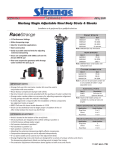
SECTION 2
INSTALLATION
5) Add the “Coil Stock O'Ride” output into the PLC program. The
signal is used to by-pass the die jam and cup jam detection when
the press is stroked without coil stock.
Note: The HSL-CUP4 will produce an “COIL STOCK MODE”
fault if cups are detected dropping while the coil stock override is
“on”. This prevents the machine from being run in production
with the coil stock override accidentally left “on”.
6) Add the “Alarm Reset” output. This signal should be “on” as long
as the system reset push-button is depressed.
________________________________________________________
2.8 HSL-CUP4 SET-UP
The HSL-CUP4 is shipped from the factory with the PLC program
loaded into the PLC section of the module. The PLS channel set-point
file “CUP7TMG” loaded in the PLS section. In most cases, the
following user variables and timing channels may have to be altered
to tune the HSL-CUP4 to the actual cupper it is controlling.
Once installed and the control system is powered back up, perform
the following to set-up and tune the HSL-CUP4. The set-up is
performed using the Keypad/Display or a PC running the set-up
program. See section 3 for a description of the Keypad commands and
menu displays of the HSL-CUP4 Keypad/Display. See section 4 for a
description of the menus, variables and how to use the Windows
based set-up program. See section 5 for a description of the menus,
variables and how to use the DOS based set-up program.
HSL-CUP4 User’s Manual
SYSTEMS Electronics Group
- 17 -
SECTION 2
INSTALLATION
________________________________________________________
2.8.1 DEFAULT SET-UP VARIABLES
As shipped, the user variables for the HSL-CUP4 are set to the
following defaults:
Brake Wear Compensation:
Enabled
Desired TDC Stop Position (Mid Speed)
Desired TDC Stop Position (High Speed)
:N
: 000
: 000
Maximum Allowed Stopping Response (degrees)
: 300
Cupper Running Speeds:
Low Speed (SPM)
High Speed (SPM)
:100
:250
Lubricator Speed Reference:
Maximum Speed
Idle Speed (Cupper stopped)
: 250
: 075
The “CUP7TMG” timing channel file, as shipped, contains the
following default timing set-points:
CHAN
ON - OFF
DESCRIPTION
CH00:
CH01:
CH02:
CH03:
CH04:
CH05:
CH06:
CH07:
CH10:
CH11:
CH12:
CH13:
CH14:
CH15:
CH16:
CH17:
120
160
200
120
140
150
140
000
___
___
___
___
___
___
___
___
TDC (High) timing
TDC (Mid) timing
TDC (Low) timing
Air Strip (High) timing
Air Strip (Mid) timing
Air Strip (Low) timing
Cup Drop Window timing
PLC Timing
-
140
180
220
200
220
230
120
020
___
___
___
___
___
___
___
___
HSL-CUP4 User’s Manual
SYSTEMS Electronics Group
- 18 -
SECTION 2
INSTALLATION
________________________________________________________
2.8.2 SET CUPPER SET-UP PARAMETERS
The Cupper set-up parameters include:
• Enabling or Disabling The Brake Wear Compensation
• Setting the Desired Mid and High Speed Stopping Points (if the
brake wear compensation is enabled)
• Setting the Maximum Allowed Stopping Response
• Setting the Cupper Running Low and High Speeds
Brake Wear Compensation: If the brake wear compensation is
used, enable it by setting the “Brake Wear Compensation Enable” to
“Y” and set the “Desired TDC Stop Position (Mid)” and “(High)”.
The “Desired TDC Stop positions” is the location of the ram when it
comes to rest after a TDC stop. Both the “Mid” and “High” desired
stopping positions are generally set to 000 degrees. Enabling the
brake wear compensation allows the HSL-CUP4 to automatically
adjust the TDC timing channels (CH00-High) and (CH01-Mid) as
necessary, such that the press will stop at the desired stopping
position regardless of the actual brake response.
If the brake wear compensation is not used, disable it by setting the
“Brake Wear Compensation Enable” to “N”. Disabling the brake wear
compensation requires the TDC (High) timing (CH00) and the TDC
(Mid) timing (CH01) signals to be set manually such that the press
stops at TDC.
Note: If the brake response then changes, the press will not stop at
the desired position if the brake wear compensation is disabled.
Maximum Allowed Stopping Response: This parameter defines
the maximum allowed brake response before a “Brake Response Too
Long” alarm is generated. If the actual brake response (number of
degrees from when the brake is activated to the position where the
press ends up at rest) when a TDC stop is performed is longer than
this number, the alarm is generated. If the actual brake response is
less, the alarm is not generated. Set this parameter to the value where
the brake response is considered too long and service to the brake
should be performed (typically 270 to 300 degrees).
HSL-CUP4 User’s Manual
SYSTEMS Electronics Group
- 19 -
SECTION 2
INSTALLATION
Cupper Running Speeds: Set the Cupper running “Low Speed”
and “High Speed” to the speeds that the cupper will actually run at
when the respective speed is selected.
Note: This is not a speed reference but is instead parameters used by
the HSL-CUP4 to know when to switch between the TDC (Low),
TDC (Mid), and TDC (High) timing as well as the Air Strip (Low),
Air Strip (Mid), and (High) timing etc.
See section 3.5.1 (Using the Keypad/Display), section 4.5.2
(Windows set-up program reference) or section 5.1.3 (DOS set-up
program reference) for details on setting the set-up parameters.
________________________________________________________
2.8.3 SET LUBRICATOR SPEED REFERENCES
Set the “Lubricator Maximum Speed” and “Lubricator Idle Speed” as
desired. These parameters are used to control the speed of the
lubricator (via the 0-10Volt lubricator speed reference output of the
HSL-CUP4 module).
Lubricator Maximum Speed: The “Lubricator Maximum Speed”
parameter is used to scale the 0-10VDC analog output such that when
the cupper is running at the speed entered in “Lubricator Maximum
Speed”, the analog output will be at 10 volts.
Lubricator Idle (Minimum) Speed: This parameter determines
the speed the lubricator will run at when the cupper is stopped (declutched).
Note: When the cupper is running, the lubricator speed reference is
proportional (as set by the “Lubricator Maximum Speed” scaling) to
the speed of the cupper. This parameter is used to provide the speed
reference when the cupper speed is zero (for lubricator jog, etc.).
See section 3.5.2 (Using the Keypad/Display), section 4.5.2
(Windows set-up program reference) or section 5.1.4 (DOS set-up
program reference) for details on setting the set-up parameters.
HSL-CUP4 User’s Manual
SYSTEMS Electronics Group
- 20 -
SECTION 2
INSTALLATION
________________________________________________________
2.8.4 SET MACHINE ZERO
Inch the cupper up to top dead center (TDC) and set the HSL-CUP4
resolver offset. See section 3.5.4 (Using the Keypad/Display), section
4.5.3 (Windows set-up program reference) or section 5.2.1 (DOS setup program reference) for details on setting machine zero.
________________________________________________________
2.8.5 VERIFY LOCATION OF CUP DROP WINDOW (CH06)
By inching the machine, verify that the “Cup Drop Window” timing
(CH06) of the HSL-CUP4 first turns “on” at the point where the cups
are first freed from the punches (see figure 2). This is the earliest
point the sensors might see the cups drop. The “Cup Drop Window”
should then be set to stay “on” all the way up to about 20 degrees
before this location (this is almost one complete stroke). This allows
the greatest amount of time for the cups to drop.
The “Die Jam” alarm is generated if a cup from any station fails to
drop within the “Cup Drop Window” timing (CH06). The “Cup Jam”
alarm is generated if any cup is detected when the “Cup Drop
Window” is “off” (cups must be clear by this time).
See section 3.5.3 (Using the Keypad/Display), section 4.5.3
(Windows set-up program reference) or section 5.2.2 (DOS set-up
program reference) for details on setting the location of the cup drop
window (CH06).
HSL-CUP4 User’s Manual
SYSTEMS Electronics Group
- 21 -
SECTION 2
INSTALLATION
________________________________________________________________________________
Figure 2 – Cup Drop Check Timing Sequence
________________________________________________________________________________
________________________________________________________
2.8.6 VERIFY MACHINE OPERATION
Once steps 2.8.2 thru 2.8.5 are complete, run the machine in normal
production (at all speeds where practical) and verify the following:
Verify Air Strip Timing: With the machine running with the coil
stock, verify that the cups are dropped with-out any problems (verify
at low, medium, and high speed). If a problem is occurring, adjust the
respective “Air Strip” timing (CH03-High Speed, CH04-Mid Speed,
CH05-Low Speed) until the problem is corrected. See section 3.5.3
(Using the Keypad/Display), section 4.5.3 (Windows set-up program
reference) or section 5.2.2 (DOS set-up program reference) for details
on adjusting CH03 thru and CH05.
HSL-CUP4 User’s Manual
SYSTEMS Electronics Group
- 22 -
SECTION 2
INSTALLATION
Verify Cup Drop Timing: With the machine running with the coil
stock, verify that no false die jam or cup jam faults are occurring. If
false die jams or cup jams are occurring, verify that the cup drop
sensors are detecting the cups when they drop. If the sensors are
detecting the cups, adjust the “Cup Drop Window” timing as
necessary to eliminate the false die jam or cup jam faults. The cups
must drop inside the “Cup Drop Window” in order to avoid a die jam
and must not be detected outside the “Cup Drop Window” in order to
avoid a cup jam..
Verify that the die jam detection is working correctly by removing the
coil stock from the press and then stroking the press with the coil
stock override “off”. The press should stop with a die jam alarm for
station #1 displayed (die jams for all stations actually occur, but #1 is
displayed since it is the lowest numbered station to fault).
Verify TDC Stops: If the brake wear compensation is enabled,
verify that the press does stop at the desired location in both the high
and the mid speeds.
Note: When the HSL-CUP4 is first installed, it will take a few
successive stops for the algorithm to program the TDC timing
channels to the correct position. Also, the compensation is enabled
after the press has been running at a fixed speed in continuous. The
TDC timing channels will not be modified when single strokes are
made or if press is started in continuous and then immediately
stopped again. Wait about 5 seconds after the press is started before
performing the TDC stop to verify the stop position.
If the brake wear compensation is disabled, manually adjust both the
TDC (High) timing (CH00) and the TDC (Mid) timing (CH01) such
that the press stops at back dead center at both respective speeds.
Note: The TDC (Low) timing must be set manually since it does not
incorporate the compensation algorithm. See section 3.5.3 (Using the
Keypad/Display), section 4.5.3 (Windows set-up program reference)
or section 5.2.2 (DOS set-up program reference) for details on
adjusting CH00 and CH01.
The Machine Is Now Set-Up And Ready To Run!
HSL-CUP4 User’s Manual
SYSTEMS Electronics Group
- 23 -