1
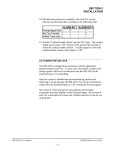
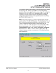
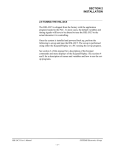
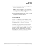
SECTION 2
INSTALLATION
________________________________________________________
2.10 TUNING THE HSL-CCSD1
The HSL-CCSD1 is shipped from the factory with the PLC program
“HSLCCSD1” loaded in the PLC section and the channel set-point
file “CCSD2TMG” loaded in the PLS section. These are the standard
programs used to implement the standard HSL-CCSD1 decorator
algorithms. In most cases, the following user variables and timing
signals may have to be altered to tune the HSL-CCSD1 to the actual
decorator it is controlling.
Once the HSL-CCSD1 is installed and the control system is powered
back up, perform the following to set-up and tune the HSL-CCSD1.
The set-up is performed using the Display/Keypad or a PC running
the set-up program.
See the HSL-CCSD1 Keypad Quick Reference for exact key depress
sequences for entering the following parameters. See section 3 of this
manual for a description of the Keypad commands and menu displays
of the HSL-CCSD1 Display/Keypad. See section 4 or 5 for a
description of the menus, variables and how to use the set-up
program.
HSL-CCSD1 User’s Manual
SYSTEMS Electronics Group
- 18 -
SECTION 2
INSTALLATION
________________________________________________________
2.10.1 DEFAULT SET-UP VARIABLES
As shipped, the user variables for the HSL-CCSD1 are set the
following defaults:
Print Trip:
Print Trip retract response time (msec)
Print Trip extend response time (msec)
: 020
: 020
Varnish Trip:
Varnish Trip retract response time (msec)
Varnish Trip extend response time (msec)
: 020
: 020
Bad Can (pin chain) Blowoff:
Blowoff solenoid “on” response time (msec)
Blowoff solenoid “off” response time (msec)
# of bad cans to blowoff for misload
# of cans to blowoff from infeed open
# of cans to blowoff from print at restart
# of cans to blowoff from varnish at restart
# of pins to pin chain blowoff port
: 015
: 020
: 001
: 005
: 000
: 033
: 028
QC Can (select-a-can) Blowoff:
Blowoff solenoid “on” response time (msec)
Blowoff solenoid “off” response time (msec)
QC can blowoff port shift offset
: 015
: 020
: 017
Spindle Trip Offset
: 022
The “CCSD2TMG” timing channel file, as shipped, contains the
following default timing set-points:
CHAN
ON - OFF
DESCRIPTION
CH00:
CH01:
CH02:
CH03:
CH04:
CH05:
CH06:
CH07:
CH10:
CH11:
CH12:
CH13:
CH14:
CH15:
CH16:
120
275
180
120
080
155
160
000
000
___
___
___
___
___
___
Print Trip timing
Varnish Trip timing
Can/No Can clock
Damaged Can Blow-off (Low speed)
Damaged Can Blow-off (High speed)
Pin Chain Blow-off (bad can) timing
Select-A-Can (QC) Blow-off timing
Spare Timing
PLC Clock Timing
CH17:
___ - ___
-
160
315
000
230
220
195
200
040
180
___
___
___
___
___
___
HSL-CCSD1 User’s Manual
SYSTEMS Electronics Group
- 19 -
SECTION 2
INSTALLATION
________________________________________________________
2.10.2 SET MACHINE ZERO
Position the machine with a spindle (any spindle - it does not have to
be spindle #1) directly centered on the no can/no print sensors and set
the offset per section 3.5.4 – Zero Machine (set Resolver Offset).
________________________________________________________
2.10.3 VERIFY LOCATION OF NO CAN/NO PRINT
SENSORS
The machine is zeroed based on the location of the no can/no print
sensors (not adjustable in the direction of can flow). With the machine
zeroed as above, both no can/no print sensors should “see” a fully
loaded can from about 320 degrees (first turn “on”) to about 40
degrees (where sensors turn “off”).
Verify that the sensors do not “see” an empty spindle (sensor too
close to spindle) and that both do see a fully loaded can (sensor not
too far out from spindle).
The sensors should also be set to “see” the very edge of the open end
of the can such that they will only detect fully loaded cans. If the
sensors are set too far out towards the dome end, they may detect cans
that are not fully loaded as being loaded which will result in a ring of
inside litho at the top of the can that is next printed on that spindle.
________________________________________________________
2.10.4 SET PIN CHAIN BLOW-OFF TIMING
Using the Keypad/Display, set the bad can (pin chain) blowoff timing
(CH05) such that the timing signal just turns “on” when the chain
(linear vacuum conveyor) blowoff port is centered between cans on
the chain (or conveyor). The signal should be 40 degrees wide.
Note: Follow steps 2.10.5 through 2.10.7 to systematically set-up the
pin chain blow-off, print trip, and varnish trip. These steps need to be
followed sequentially as they depend on each other and the order they
are executed.
HSL-CCSD1 User’s Manual
SYSTEMS Electronics Group
- 20 -
SECTION 2
INSTALLATION
________________________________________________________
2.10.5 SET # OF CANS TO PIN CHAIN BLOW-OFF PORT
Using the Keypad/Display:
1) Set the “# Of Pins To Pin Chain Blowoff Port”. Count the number
of cans from where cans are transferred from the spindle wheel to
the linear vacuum conveyor to the bad can pin chain blowoff port.
Subtract 2 and enter this number (this is still just an
approximation).
2) Set the “# Of Bad Cans To Blowoff For Misload” equal to three.
Run the machine at low speed with cans and induce misloads.
Verify that for a miss-load three bad cans are blown off (misloaded silver can blown off at damaged can blowoff port, printed
cans ahead and behind mis-loaded can blown off at pin chain
port). If not adjust “# Of Pins To Pin Chain Blowoff Port”
accordingly until they are.
Note: Silver cans may get through the line until this variable is
set-up properly. Once this is set, you should be blowing off the
can ahead of the misload (missing can), the misloaded can (which
is missing) and the can behind the misload.
3) Disable the damaged can blow-off by pulling the fuses for both
the drive and offside damaged can blow-off solenoids.
Note: For the next set-up steps, misloads can be induced by pressing
the “blank” key on the Keypad/Display. This simulates a misloaded
can by blanking out the no can/no print sensor input for one can space
in the logic. This allows a fully loaded (non damaged) can to be
blown off at the pin chain blow-off (without being printed). This is
done so that the print and varnish trip can be verified by inspecting
the can ahead, misloaded (silver) can, and the can behind.
Proceed To Step 2.10.6
HSL-CCSD1 User’s Manual
SYSTEMS Electronics Group
- 21 -
SECTION 2
INSTALLATION
________________________________________________________
2.10.6 SET PRINT TRIP “RETRACT”/”EXTEND” RESPONSE
TIMES
Using the Keypad/Display, verify the print trip by running the
machine at high speed, inducing mis-loads by pressing the “blank”
key on the keypad and observing the cans blown off of the pin chain.
With the damaged can blow-off disabled, the mis-loaded can will now
be blown off at the pin chain blowoff and should be completely silver.
The can ahead of the mis-load (can the print retracted after) should be
blown off at the pin chain blow off port and should be fully printed.
The can behind the mis-load (the can the print extended before)
should be blown off at the pin chain blow off port and should be fully
printed.
If the 2nd can blown-off (which should be the misload and fully
silver) has any print on it from the leading edge of the label image,
the “Print Trip retract (out) response time” is too short and is not
retracting soon enough. Increase the “Print Trip retract (out) response
time” by 5 milliseconds and try again. Continue increasing this time
until the 2nd can (misloaded can) is fully silver and the can ahead of it
(the 1st can) is fully printed. If the 1st can is not fully printed, the
“Print Trip retract (out) response time” is too long and is retracting
too soon. Decrease the “Print Trip retract (out) response time” by 5
milliseconds and try again. Continue decreasing this time until the 1st
can is fully printed and the 2nd can (misload) is fully silver (no print
on it).
If the 3rd can (can following the misload) is not fully printed, the
“Print Trip extend (in) response time” is too short and is not
extending soon enough. Increase the “Print Trip extend (in) response
time” by 5 milliseconds and try again. Continue increasing this time
until the 3rd can is fully printed and the 2nd can (misload) is fully
silver. If the 2nd (misload) can has any print on it from the trailing
edge of the label image, the “Print Trip extend (in) response time” is
too long and is extending too soon. Decrease the “Print Trip extend
(in) response time” by 5 milliseconds and try again. Continue
decreasing this time until the 2nd can (misload) is fully zero and the
3rd can is fully printed.
HSL-CCSD1 User’s Manual
SYSTEMS Electronics Group
- 22 -
SECTION 2
INSTALLATION
________________________________________________________
2.10.7 SET VARNISH TRIP “RETRACT”/”EXTEND”
RESPONSE TIME
Set the varnish extend and retract response times in the same fashion
as was done for the print. In general the mis-loaded can should have
no varnish on it and the cans ahead and behind should be fully
varnished.
Once The Print And Varnish Are Set-Up:
1) Set the “# Of Bad Cans To Blowoff For Misload” to “1”
2) Reduce the “# Of Pins To Pin Chain Blowoff Port” by “1” such
that only the misloaded (silver can) is blown-off
3) Enable the damaged can blow-off by installing the fuses for both
drive and offside damaged can blow-off solenoids.
________________________________________________________
2.10.8 SET # OF CANS TO BLOW-OFF AT RESTART
Using the Keypad/Display, set the following as desired
• “# Of Cans To Blowoff From Infeed Open”
• “# Of Cans To Blowoff From Print At Restart”
• “# Of Cans To Blowoff From Varnish At Restart”
________________________________________________________
2.10.9 SET QC BLOW-OFF SHIFT OFFSET
Using the Keypad/Display, set the “QC can blowoff port shift offset”
as follows:
1) Dial in spindle #1 on the select-a-can thumbwheel switch
2) With the machine running slowly, mark cans printed on spindle
#1 so they can be identified while they are on the chain.
3) Press the select-a-can pushbutton and observe the can that was
blown off with the location of a can printed on spindle #1.
4) Add the number of cans difference between the can blown off and
the can printed on spindle number one to the “QC can blowoff
port shift offset”.
Note: This variable must be a number between 1 and 24. Once setup, verify that a can from spindle #1 is blown off when 1 is dialed in
on the thumbwheel and the select-a-can pushbutton is pressed.
HSL-CCSD1 User’s Manual
SYSTEMS Electronics Group
- 23 -
SECTION 2
INSTALLATION
________________________________________________________
2.10.10 SET SPINDLE TRIP SHIFT OFFSET
Using the Keypad/Display, set the “Spindle trip shift offset” as
follows:
1) Initially set the “Spindle trip offset” to zero.
2) Wrap a piece of tape around the drive side spindle #1 such that
cans will not load on this spindle.
3) Run the machine very slowly with the can gate open and verify
that indeed cans do not load on spindle #1 and the print is tripped
for that spindle.
4) Observe the “Trips Per Spindle” data and determine which spindle
is being incremented. The spindle number that should be
incrementing is the drive side spindle #1. If it is not, subtract 1
from the spindle number that is being incremented and enter this
value as the spindle trip offset.
Note: This variable must be a number between 0 and 23.
5) Verify that the spindle #1 count is incremented every time the
print trips for spindle #1. If it still increments another spindle
number other than the drive side #1, continue adjusting the
“spindle trip offset” until it does.
6) Stop the machine and remove the tape from spindle #1.
The Machine Is Now Set-Up And Ready To Run!
HSL-CCSD1 User’s Manual
SYSTEMS Electronics Group
- 24 -