1
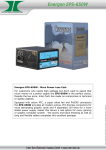
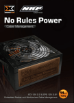
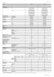
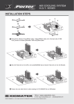
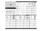
No Rules Power
Cable Management ATX12V 2.2 & EPS 12V 2.91 Version
TABLE OF CONTENTS
A Introduction
B Product Features
C Accessary Kits
D Product Information
E Connectors & Modularized Cable Management
F Installation
G +12V Rail Distribution and PCI-E Connectors
H SPEC Table
I
Other Specification
J Trouble Shooting
K Contact Us
A
INTRODUCTION
Statement
We live up to the promise of XIGMATEK logo in our unending quest for excellence.
Shall you have any suggestion or comments, please access our website:
Http://www.xigmatek.com
or e-mail to:
[email protected]
We appreciate your kindly feedback and you will receive the prompt response from
our customer service team.
Please take the time in familiarizing yourself with the power supply, its connectors
and the contents of this manual before proceeding with the installation of the
power unit. You will need a Philips crosshead screwdriver, perhaps your PC case
manual and most certainly your motherboard manual.
Should you have any questions regarding the content of the manual, please contact
XIGMATEK directly. Failure to follow the proper procedures may cause severe
bodily harm or PC component damage.
Warnings and Cautions
1.Do not pull the AC power cord when the power supply is in use or the damages to the components will occur.
2.Do not store the Power Supply in high humidity and high temperature environment.
3.When using No Rules Power Cable management 1200W power supply under
testing conditions where the power supply unit is not installed in a PC with its components, please follow the steps below:
•Please take a paper clip and untwist it.
•Make sure the power supply unit is in the “OFF” position.
•Locate the 20+4 pin motherboard connector from the power supply unit.
•Plug one side of the paper clip into the green wire hole.
•Plug the other side of the paper clip into any of the black wire holes.
•Turn on the PSU to see if the power supply fan(s) turn(s) on.
4.High voltages exist in the power supply. Do not open the power supply case unless you are an authorized service technician or electrician.
5.All warrantees and guarantees shall be voided should there be a failure to comply with any of the warnings and cautions covered in this manual.
B
PRODUCT FEATURES
Product Features
1.8 pin PCI-E Connector NEW!!
No Rules Power supplies come with three of the latest 8-pin PCI-E connectors
required for the next generation NVIDIA and ATI graphics cards. These new
defined 8-pin connectors are downward compatible with the existing 6-pin PCI-E
connectors with an 8 pin to 6 pin converter. Thus, with the included three 6-pin/
8-pin connectors, No Rules Power support up to three high-end graphic cards.
2.Excellent Efficiency (up to 87%)
No Rules Power provide excellent efficiency and hence reducing energy
consumption. That in return reduces customers’ electricity bill.
3.140mm Ball-Bearing Fan
The 140mm ball bearing fan effectively increases the airflow inside the PSU and
decreases the ambient temperature.
4.Extremely good voltage regulation (±3%)
This feature allows tighter load regulation (±3%) than other power supplies (±5%)
and increase system voltage stability.
5.MTBF > 120,000 hours (Highly reliable)
120,000 hours of MTBF (Mean Time between Failures) goes above and beyond all
ATX specifications.
6.Four Independent +12V rails
Four independent +12V rails are provided to support the high-end graphic card
and PC system.
7.Cable Management
Cable Management enables users to remove unused cables and significantly
improves the airflow in the chassis.
8.Industrial grade components (capacitor, transformer, etc)
All components are specially designed for industrial environment and extreme
conditions.
9.Hi-Tech Black Coating
With special Hi-Tech Black coating, No Rules Power looks professional, elegant
and unique.
10.High +5VSB Output
Built-in higher +5VSB (from 2A to 3.5A (PS-ON status)) supports up to 12
USB devices. Also, even the system is power off, USB devices can still be
charged by the 3A sustained output.
C
ACCESSARY KITS
1 No Rules Power supply unit
(w/one 20+4 pin main power connector, one 4+4 pin+
12V power connector, and one 8 pin powerconnector)
2 8 pin PCI-E connector
1
3 6 pin PCI-E connector
4 5 pin SATA connector
5 4 pin peripheral connector
6 AC Input power cord
7 4 mounting screws
8 User manual
9 Cable ties
10 Power supply dust bag
11 Cable kits bag
2
3
4
5
6
7
8
One Torghpower 1200W power supply unit(w/
one20+4pin main power connector,one
4+4pln+12V) power connector, and one 8pln
power connector)
9
10
11
D
PRODUCT INFORMATION
1.OUTPUT & INPUT VOLTAGE
2.1INPUT VOLTAGE:100V~240V 47HZ~63HZ
3.1.2 OUTPUT VOLTAGE:
Model / Set
+3.3V
+5V
+12V1
+12V2
+12V3
+12V4
-12V
+5Vsb
Total
Power
NRP-HC1001
30A
28A
20A
20A
36A
36A
0.8A
3.5A
1000W
NRP-HC1201
30A
28A
20A
20A
36A
36A
0.8A
3.5A
1200W
NRP-HC1501
30A
30A
20A
20A
40A
40A
0.8A
3.5A
1500W
E
CONNECTORS & MODULARIZED CABLE MANAGEMENT
Connectors
Main Power
CPU
CPU
Peripheral
SATA
Floppy Disk
PCI-E
PCI-E
Model / Set Connector Connector Connector Connector Connector Connector Connector Connector
(20+4 pin)
(4+4 pin)
(8 pin)
(4 pin)
(5 pin)
(4 pin)
(8 pin)
(6 pin)
NRP-HC1001
1
1
1
8
8
2
3
3
NRP-HC1201
1
1
1
8
8
2
3
3
NRP-HC1501
1
1
1
8
8
2
3
3
a.Main Power Connector (20+4 pin)
Support the latest ATX 12V 2.2 system motherboard
24
23
22
21
20
19
18
17
16
15
14
13
12
11
10
9
8
7
6
5
4
3
2
1
Voltage
Color
Color
Voltage
+3.3V
Orange
1
13
Orange
+3.3V
+3.3V
Orange
2
14
Blue
+12V
COM
Black
3
15
Black
COM
+5V
Red
4
16
Green
PS_ON#
COM
Black
5
17
Black
COM
+5V
Red
6
18
Black
COM
COM
Black
7
19
Black
COM
PWR_ON
Gray
8
20
N/C
N/C
+5Vsb
Purple
9
21
Red
+5V
+12VDC
Yellow
10
22
Red
+5V
+12VDC
Yellow
11
23
Red
+5V
+3.3V
Orange
12
24
Black
COM
b.CPU Connector (4+4 pin)
Support both dual CPU and single CPU systems by simply combining (8 pin) or splitting (4 pin X 2)
the connectors
5
4
6
3
7
2
8
1
Voltage
Signal
Pin
Black
GND
1
Black
GND
2
Black
GND
3
Black
GND
4
Yellow
+12VDC
5
Yellow
+12VDC
6
Yellow
+12VDC
7
Yellow
+12VDC
8
Color
Signal
Pin
Black
COM
1
Black
COM
2
Black
COM
3
Black
COM
4
Yellow
+12VDC
5
Yellow
+12VDC
6
Yellow
+12VDC
7
Yellow
+12VDC
8
c.CPU Connector (8 pin)
Support the latest 8 pin Quad Core system motherboard
5
4
6
3
7
2
8
1
d.PCI-E Connector (8 pin)*
Support next generation 8 pin sockets on high-end graphic cards and can support the
existing 6 pin sockets by connecting to the 8 pin to 6 pin converter.
5
4
6
3
7
2
8
1
Color
Signal
Pin
Yellow
+12VDC
1
Yellow
+12VDC
2
Yellow
+12VDC
3
Black
GND
4
Black
GND
5
Black
GND
6
Black
GND
7
Black
GND
8
e.PCI-E Connector (6 pin)*
Support the latest high-end graphic cards with 6 pin socket
A 6 pin & a 8 pin PCI-E connectors can be connected to the same graphic card if there are two 6 pin sockets or both 8 pin socket and 6 pin sockets available on the card. Please refer to Section 6.2 for more information.
6
4
3
1
Color
Signal
Pin
Yellow
12VDC
1
Yellow
12VDC
2
Yellow
12VDC
3
Black
COM
4
Black
COM
5
Black
COM
6
f.SATA Connector (5 pin)
Support the new generation high-speed SATA devices
Color
Signal
Pin
Yellow
+12VDC
1
Black
COM
2
Red
+5VDC
3
Black
COM
4
Orange
+3.3VDC
5
g.Peripheral Connector (4 pin)
Support IDE/SCSI (HDD/CD/DVD..etc) devices
1
4
Color
Signal
Pin
Yellow
+12VDC
1
Black
COM
2
Black
COM
3
Red
+5VDC
4
Color
Signal
Pin
Red
+5VDC
1
Black
COM
2
Black
COM
3
Yellow
+12VDC
4
h.Floppy Disk Connector (4 pin)
Support Floppy Disk and some other additional devices
1
4
Modularized Cable Management:
Users can optimize the cables arrangement within the chassis by using only what
users need. This feather increases the airflow and reduces the overall ambient
temperature within the chassis, also improves the overall look and tidiness of the
system.
Embedded Socket and
Modularized Cable
Management Design:
PCI-Express Connector
SATA, Peripheral, and
Floppy Connector
PCI-Express
Connector
SATA,
Peripheral,
and Flopp
Connector
F
INSTALLATION STEPS
To prevent electrical shocks, please disconnect the power cord from your existing
power supply unit. No Rules Power 1200W Power Supply has automatic voltage
selector which will automatically change to 100V-240V PSU.
STEP 1
After install the power supply unit into the chassis and then
connect the 20+4-pin main power cable to motherboard 20 pin
or 24 pin socket.
1
2
3
STEP 2
Connect the 4+4-pin/8-pin +12V auxiliary
power connector to the motherboard.
(Users can use either 4 pins or 8 pins,
depending on the motherboard. Please check
with the motherboard user’s manual.)
STEP 3
Connect the 6 pin/8 pin PCI-Express connector to your graphic card if
needed. (Notice: Before the connection, please refer to Section 6.2 for
more information.)
1
2
STEP 4
Connect the 4 pin power connector to peripheral devices such as DVD-Burner,
hard drive, and etc. In addition, a user can connect the 3-pin floppy power
connector to connect the floppy drive
1
2
3
If there are S-ATA hard disk drives present, there are also Serial ATA connectors available.
1
G
2
+12V Rail Distribution & PCI-E Connectors
+12V Rail Distribution
W0133 1200W
24 pin + 12V
12V1
4+4 pin + 12V
12V2
8 pin + 12V
12V2, 12V3
Peripheral & Floppy
12V1
S-ATA
12V1
6 pin Modular PCI-E
12V3
6 pin Modular PCI-E
12V3
6 pin Modular PCI-E
12V4
8 pin Modular PCI-E
12V3
8 pin Modular PCI-E
12V4
8 pin Modular PCI-E
12V4
PCI-E Connectors and+12V
Rails Distributio
Please carefully read the table and
suggestions below when connecting the 6
pin/8 pin connectors to your graphic card(s),
especially when there are more than one PCI-E
sockets available on your card(s).
12V3
6 pin
X
6 pin
X
X
6 pin
8 pin
12V4
X
8 pin
X
8 pin
X
Please be noticed that when trying to connect
more than one connector to a graphic card,
it is strongly recommended to choose the
connectors from exactly the same +12V rail.
H
SPEC TableEPS
SPEC Table
NRP-HC1001
Model
NRP-HC1001
SPECIFICATION
Power
1000W
Dimension
200mm(L)x160mm(W)x86mm(H)
Switches
PFC
Cooling System
Noise
P.G. Signal
Efficiency
Hold-up Time
ATX Logic on-off additional power rocker switch
Active PFC (PF > 0.9)
140mm Fan, 2300RPM±10%
16 dBA at 1300RPM
100-500 ms
Up to 87%
16 ms
INPUT
100-240VAC
50/60Hz
120,000 hrs minimum (at 25℃)
13A
Output
Max/Min
Regulation *1 Ripple & Noise *2
Output
20A/1A
+3, -3%
120mV
36A/1A
+3, -3%
120mV
500W
30A/0.5A
+3, -3%
50mV
20A/1A
+3, -3%
120mV
36A/1A
+3, -3%
120mV
500W
30A/0.5A
+3, -3%
50mV
0.8A/0A
+10, -10%
120mV
9.6W
3.5A/0A
+3%, -5%
50mV
17.5W
1000W
1100W
Input Voltage
Input Frequency Range
MTBF
Input Current
+12V1
+12V4
+3.3V
+12V2
+12V3
+5V
-12V
+5Vsb
Total Power
Peak Power
1. +5Vsb operate at 3.5A max load base on PS-ON mode. If PS-OFF +5Vsb only operate at 3A max load.
2. Add 0.1μF capacitors across output terminal during ripple & noise test.
Environment
Operating Temp.
Storage Temp.
Operating Humidity
Storage Humidity
Over Voltage Protection
Over Current Protection
Under Voltage Protection
Short Protection
10
10℃ to 50℃
-20℃ to 70℃
20% to 90%, non-condensing
5% to 95%, non-condensing
Protection
DC Rail
Trigger Point/Range
+3.3V trip point
4.5 Vmax
+5.0V trip point
7.0 Vmax
+12.0V trip point
15.6 Vmax
+3.3V
33A ~ 50A
+5.0V
33A ~ 50A
+12V1 & +12V2
22A ~ 35A
+12V3 & +12V4
39A ~ 55A
+3.3V trip point
2.0 Vmin
+5.0V trip point
3.3 Vmin
+12.0V trip point
8.5 Vmin
All output to GND
SPEC Table
NRP-HC1201
Model
NRP-HC1201
SPECIFICATION
Power
1200W
Dimension
200mm(L)x160mm(W)x86mm(H)
Switches
PFC
Cooling System
Noise
P.G. Signal
Efficiency
Hold-up Time
ATX Logic on-off additional power rocker switch
Active PFC (PF > 0.9)
140mm Fan, 2300RPM±10%
16 dBA at 1300RPM
100-500 ms
Up to 87%
16 ms
INPUT
100-240VAC
50/60Hz
120,000 hrs minimum (at 25℃)
13A
Output
Max/Min
Regulation *1 Ripple & Noise *2
Output
20A/1A
+3, -3%
120mV
36A/1A
+3, -3%
120mV
600W
30A/0.5A
+3, -3%
50mV
20A/1A
+3, -3%
120mV
36A/1A
+3, -3%
120mV
600W
30A/0.5A
+3, -3%
50mV
0.8A/0A
+10, -10%
120mV
9.6W
3.5A/0A
+3%, -5%
50mV
17.5W
1200W
1300W
Input Voltage
Input Frequency Range
MTBF
Input Current
+12V1
+12V4
+3.3V
+12V2
+12V3
+5V
-12V
+5Vsb
Total Power
Peak Power
1. +5Vsb operate at 3.5A max load base on PS-ON mode. If PS-OFF +5Vsb only operate at 3A max load.
2. Add 0.1μF capacitors across output terminal during ripple & noise test.
Environment
Operating Temp.
Storage Temp.
Operating Humidity
Storage Humidity
Over Voltage Protection
Over Current Protection
Under Voltage Protection
Short Protection
10℃ to 50℃
-20℃ to 70℃
20% to 90%, non-condensing
5% to 95%, non-condensing
Protection
DC Rail
Trigger Point/Range
+3.3V trip point
4.5 Vmax
+5.0V trip point
7.0 Vmax
+12.0V trip point
15.6 Vmax
+3.3V
33A ~ 50A
+5.0V
33A ~ 50A
+12V1 & +12V2
22A ~ 35A
+12V3 & +12V4
39A ~ 55A
+3.3V trip point
2.0 Vmin
+5.0V trip point
3.3 Vmin
+12.0V trip point
8.5 Vmin
All output to GND
11
SPEC Table
NRP-HC1501
Model
NRP-HC1501
SPECIFICATION
Power
1500W
Dimension
200mm(L)x160mm(W)x86mm(H)
Switches
PFC
Cooling System
Noise
P.G. Signal
Efficiency
Hold-up Time
Input Voltage
Input Frequency Range
MTBF
Input Current
+12V1
+12V4
+3.3V
+12V2
+12V3
+5V
-12V
+5Vsb
Total Power
Peak Power
ATX Logic on-off additional power rocker switch
Active PFC (PF > 0.9)
140mm Fan, 2300RPM±10%
16 dBA at 1300RPM
100-500 ms
Up to 87%
10 ms
INPUT
230VAC
47/63Hz
120,000 hrs minimum (at 25℃)
10A
Output
Max/Min
Regulation *1 Ripple & Noise *2
Output
20A/1.0A
+3, -3%
240mV
40A/1.0A
+3, -3%
240mV
750W
30A/0.5A
+3, -3%
100mV
20A/1.0A
+3, -3%
240mV
40A/1.0A
+3, -3%
240mV
750W
30A/0.5A
+3, -3%
100mV
0.8A/0.0A
+10, -10%
240mV
9.6W
3.5A/0.0A
+3%, -5%
100mV
17.5W
1500W
1600W
1. +5Vsb operate at 3.5A max load base on PS-ON mode. If PS-OFF +5Vsb only operate at 3A max load.
2. Add 0.1μF capacitors across output terminal during ripple & noise test.
Environment
Operating Temp.
Storage Temp.
Operating Humidity
Storage Humidity
Over Voltage Protection
Over Current Protection
Under Voltage Protection
Short Protection
12
10℃ to 50℃
-20℃ to 70℃
20% to 90%, non-condensing
5% to 95%, non-condensing
Protection
DC Rail
Trigger Point/Range
+3.3V trip point
4.5 Vmax
+5.0V trip point
7.0 Vmax
+12.0V trip point
15.6 Vmax
+3.3V
33A ~ 50A
+5.0V
33A ~ 50A
+12V1 & +12V2
22A ~ 35A
+12V3 & +12V4
42A ~ 60A
+3.3V trip point
2.0 Vmin
+5.0V trip point
3.3 Vmin
+12.0V trip point
8.5 Vmin
All output to GND
I
Other Specification
Inrush Current:
55A max. when AC input 115Vac at 25℃ cold start.
110A max. when AC input 230Vac at 25℃ cold start.
Power Efficiency
80% (min.) at full load (typical) and 115Vac input
CE Requirements
1.Conducted EMI
•Meet FCC: Class B
•Meet CISPR 2 2: Class B
•Meet BSMI: Class B
2.Safety Standards
•Meet CUL (UL 60950)
•Meet TUV En60950
•Meet CB (IE C 950)
•Meet CE
3.Harmonic Meet IEC1000-3-2, Class D
J
Trouble Shooting
Condition 1:
No DC output. The fan or fans are motionless. Check:
•Is the AC inlet plug firmly plugged into the PSU inlet socket?
•Is the wall socket, extension power cord, power strip or surge protector in use, fully functional and wall power switch turned ‘ON’?
•Is the Main Board socket (20+4 pin) plug fully and firmly inserted?
Condition 2:
The fan or fans began rotating and then stopped. The system hangs without
proceeding any further. Check:
•Are the peripheral connectors firmly plugged into accessory devices, such as the main hard drive, CD ROM, etc?
•If a plug has been inadvertently connected in an off-set or reversed position, unplug the AC power source, reconnect the offending connectors and then wait for 30 seconds before replug in the AC power source and try again.
Note: If the power supply is still unable to power up after following the above
instruction, please send the unit back to your dealer or retailer for after sales
service.
13