1
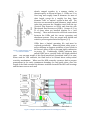
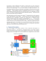
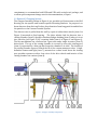
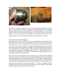
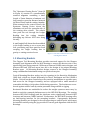
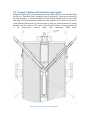
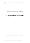
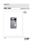
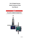
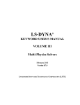
Description and Operational Experience of the Stern Labs Flux Detector Removal Tool System B. Simons1, G. Hadaller1, K. Merrifield2, B. Ballantyne3 Submitted for the 10th International Conference on CANDU Maintenance, May 2014 1 Stern Laboratories, 1592 Burlington St. East, Hamilton, Ontario, Canada, L8H 3L3, www.sternlab.com. KLM Nuclear Solutions, 828 Elgin St., Port Elgin, Ontario, Canada, N0H 2C4 (formerly of Bruce Power) 2 Intoo (Innovating Tooling) Solutions, 4 MacGregor Beach Road, Kincardine, Ontario, N2Z 1J5 (formerly of Bruce Power) 3 Abstract The Flux Detector Removal Tool (Chopper Tool) is a system for removing and compacting Single Individually Replaceable (SIR) In-Core Flux Detectors (ICFD) from a CANDU reactor. The Chopper Tool was produced in response to customer demand for a portable, modular system suitable for use with either Vertical or Horizontal Flux Detector (VFD or HFD) housings that could allow multiple ICFDs to be replaced in a single shift without modifications to the primary containment boundary. The system was developed in several phases, funded by a CANDU Owner’s Group (COG) joint project, and has been successfully used at multiple CANDU stations, most recently to remove 9 vertical ICFDs at the Darlington NGS. This paper reviews the original design constraints, outlines the final system design, and details the tests required for factory acceptance of each tool system. Some problems with earlier versions of the Chopper Tool, and the research and development required to resolve them are highlighted. Finally the results of the most recent ICFD removal campaign are presented. The successful implementation of the Chopper Tool demonstrates Stern Laboratories’ ability to research and develop new reactor maintenance tooling, and reflects well on the COG framework for pooling expertise and resources amongst CANDU utilities. Background ICFDs, also known as Self Powered Detectors (SPDs), are instruments used to measure the neutron flux inside the core of a CANDU reactor. They consist of an interior wire surrounded by concentric layers of ceramic insulation and Inconel sheath, swaged together in a manner similar to thermocouples, as shown in Figure 1. ICFDs are 12 to 14m long, and roughly 1mm in diameter for most of their length, except for a roughly 1m long, 3mm diameter “bulb” or “emitter” section at their end. The detectors are mounted in small diameter, single ended tubes that penetrate the Calandria vessel from the top (Vertical Flux Detectors or VFDs) and from the side (Horizontal Flux Detectors or HFDs). Groups of 12 or 13 of these tubes are bundled together in a “well housing”. These wells house the electrical connections between the ICFDs and the reactor operating and shutdown systems. They are purged with helium and sealed to protect against moisture ingress [1, 2] ICFDs have a limited operating life, and must be replaced periodically. Removing them safely poses a major challenge as neutron activation of trace cobalt in the Inconel causes ICFDs to become highly radioactive Figure 1 ICFD Schematic from in service [3]. Traditionally CANDU operators have U.S. Patent 4284893 pulled ICFDs into a specially built, full length shielded flask. The size and weight of this flask introduced operational risks of its own. When used for VFD removals, the flask had to be hoisted above safety-critical reactivity mechanisms. When used for HFD removals, operators had to prepare penetrations in the vault containment boundary for long guide tubes, since the length of the flask exceeded the distance available between the HFD well housings and the inner reactor vault wall. Figure 2 Chopper Tool Layout (HFD Removal at Darlington / Bruce) In response to these challenges, the authors2, 3 began work on a new concept for ICFD removal, shown in Figure 2. In this concept, a short portable tool would be affixed to the well housings. The tool would contain two simple mechanisms – one for pulling an ICFD wire from its well tube, and another to slice the wire into short “particles”. These particles would be transported from the tool to a smaller shielded flask stationed away from any reactivity devices via a pneumatic vacuum system. The device would be monitored and controlled remotely. Removal of each detector would take only a few minutes. After fabricating a proof-of-concept, the authors2, 3 brought the idea to the attention of the Candu Owner’s Group (COG). A Joint Project [4] was initiated and Stern Laboratories was contracted to develop the concept into a commercial IFCD removal system meeting COG members’ specifications [5, 6, 7]. The first ICFD “Chopper Tool” systems were manufactured in 2007, and used to successfully remove detectors in the Wolsong and Bruce NPPs. Experience gained from these campaigns [8, 9] led to the initiation of a second COG Joint Project [10] to develop a “Mark II” ICFD Chopper tool. This paper will describe the design and operational experience of Stern Labs’ Mark II ICFD removal tool. 1. Technical Description The ICFD Chopper Tool System consists of four connected sub-systems, as illustrated in Figure 3: the Removal / Chopping system, the Vacuum Transfer System, the Particle Storage system, and the Supply / Control system. This modular design permits the Chopper Tool to be installed in the cramped work areas inside Figure 3 Chopper Tool System Diagram containment, to accommodate both HFDs and VFDs with a single tool package, and to allow quick component change-outs for decontamination, or repair. 1.1 Removal / Chopping System The Chopper Assembly, shown in Figure 4, is a portable tool that mounts to the Well Housing via site-specific and location-specific Mounting Brackets. Its purpose is to draw detectors from their well tubes, chop them into 3mm long particles and deliver the particles to the Vacuum Transfer System. The detector wire is pulled from the well by a pair of rubber drive wheels (item 1 in Figure 4) mounted at fixed spacing. The drive wheels feed the detector into a cutting chamber (item 2) through a hardened ledger bushing (item 3) where it is cut into particles (see Figure 5) by a rotating blade (item 4 in Figure 4 and Figure 6). The two mechanisms are connected via a gear train and a single air motor (item 5) drives both. The top of the cutting chamber is covered by an acrylic viewing port (item 6), separated by a thin gap that forms the chamber’s air inlet. The bottom of the cutting chamber tapers to match the ID of the vacuum transport tubes. A highdefinition camera and light (item 7), mounted on a short boom above the viewing port provides operators with a clear view of the drive wheels and interior of the cutting chamber via a mirror (item 8). Figure 4 Chopper Assembly Components Figure 6 Chopped Detector Particles Figure 5 Cutter Blade The Mark II Chopper Assembly itself is divided into quickly replaceable modules. The air motor can be removed after removal of a single ball detent pin. The ledger bushing, cutting blade and cutting chamber are mounted together in a “Center Block Module” which can be removed and replaced in a manner similar to the Motor Module. The camera, light, mirror and boom disconnect from the viewing port as a single module, and can be repositioned without losing its alignment or focus. 1.2 The “Last Inch” Solution Ensuring that the end of the ICFD enters the cutting chamber after it has cleared the drive wheels was a focus of much development work. Ordinarily the small pressure differential between the cutting chamber and atmosphere is enough to force this “last inch” of wire, shown in Figure 7, through the Ledger Bushing. However it was observed during tests with the Mark I Chopper Tool that the deformation caused by the cutting process could lodge a short particle inside the Ledger Bushing with more friction than the pressure differential could overcome. Consequently a pair of redundant “Clearing Devices” was added to the Mark II to dislodge any detector wire remaining outside the cutting chamber. The “Downstream Clearing Device” (item 9 in Figure 4) consists of a short length of flexible cable that can be inserted into the Ledger Bushing through the gap between the Ledger Bushing and the downstream edge of the drive wheels. Once operators have confirmed via teledosimetry and video that a length of detector remains wholly inside the Ledger Bushing, they can actuate the Downstream Clearing Device from a safe distance by means of a long “Push-Pull Cable”. The device is adjusted prior to installation to ensure that the flexible wire reaches the entire length of the Ledger Bushing without penetrating the Cutting Chamber. The “Upstream Clearing Device” (item 10 in Figure 4) consists of a pneumatically actuated magazine containing a short length of 3mm diameter aluminum rod, long enough to span the distance between the drive wheels and the cutting chamber. When actuated at the control console, the Upstream Clearing Device injects the aluminum rod into the upstream side of the rotating drive wheels. The wheels then push the rod through the Ledger Bushing into the cutting chamber, dislodging any leftover ICFD wire along the way. A small angled ball detent has been added to the ledger bushing to act as a one-way lock, preventing any short particles from escaping the ledger bushing due to gravity or cutting reaction forces. Figure 7 "Last Inch" of detector wire after clearing drive wheels 1.3 Mounting Brackets The Chopper Tool Mounting Brackets provide structural support for the Chopper Assembly, and alignment with the Well Housing to ensure the detector wire is not significantly bent during removal. Differences between CANDU reactor designs, and between HFD and VFD work areas have led to the design of six unique Mounting Bracket types. All Mounting Bracket designs connect to the Chopper Assembly using a standardized attachment using two quick-release pins. Vertical Mounting Brackets anchor into the openings in the Reactivity Mechanism (RM) deck, which are shaped differently for Bruce, Darlington and the CANDU-6 plants. Vertical brackets extend above the reactivity mechanisms to provide space and access for the Chopper Assembly, and are equipped with a small amount of removable shielding to help reduce fields during operation. The brackets are crossbraced against seismic loads by station personnel using scaffold or rigging. Horizontal Brackets are unshielded to reduce the weight operators must carry by hand to reach the cramped platforms next to the HFD Well Housings. The spacing between HFD Well Housings and the platforms varies significantly between HFD locations and between CANDU stations. Furthermore, the HFD Well housings offer no load-bearing interface for the mounting brackets. Consequently Horizontal Mounting Brackets are designed to be self-supporting on scaffold poles, which must be installed carefully using the jigs provided to ensure good alignment with the Well Housings. 1.4 Vacuum Transfer and Particle Storage System Chopped ICFD Particles are transported from the Center Block to the Shielded Flask by way of a “Flask Inlet Tube” assembly (item 3 in Figure 8). Particles are carried by air flow through a continuous length of 16mm ID polyethelyne tube no more than 10m long. The tube terminates inside a filtered, stainless steel Canister at the center of the Shielded Flask (item 2), such that there is only one seam between the Cutting Chamber and the Canister. The outlet of the filtered Canister is connected (item 4) to an air-powered vacuum pump with integrated HEPA filter. Figure 8 Canister and Flask in Operating Mode The Canister has sufficient volumetric capacity to store 12 full-length detectors, or the contents of one complete Well Housing, and still maintain enough filter area to guarantee air flow. Station-specific radioactivity storage limits may further constrain the number of detectors stored in each Canister. Once filled, the Canister is sealed permanently via threaded plugs with tin-alloy seal rings. These seals are designed to prevent moisture ingress during intermediate storage < 30 years. However the Canister is not designed as a waste disposal container. Operators must ensure that the Canisters are enclosed in a certified enclosure before permanent disposal. A Flask with 200mm of lead shielding on all sides encloses the Canister. Plans to manage the filled canisters differ between CANDU operators, so the Flask is designed to accommodate as many options as possible. The Canister may be stored in its Flask permanently, locked in place with stainless steel latch bars and security seals. Alternatively, the Flask can be unloaded into another shielded enclosure through vertical or horizontal transfer. The Flask may be unloaded underwater so that the Canister can be stored for the intermediate term in the Irradiated Fuel Bay (IFB). The Flask is not designed as a radioactive material transport package, and must be packed inside a certified container before being transported off-site. 1.5 Supply / Control System and Operating Sequence During removal and cutting operations, the Chopper Tool system is monitored and controlled from a safe distance about 30m away. A Control Console provides a central supply connection for plant compressed air. From the console, compressed air lines run to the Chopper Assembly Motor Module, and to the Vacuum Pump through and umbilical. Compressed air was chosen to power the system for several reasons: The airpowered vacuum pump has no moving parts, increasing its reliability. The airpowered Chopper Motor has excellent low and stall speed torque characteristics, and is light-weight. The Manifold in the Control Console ensures that the Motor cannot run without also supplying power to the Vacuum Pump. Chopper Tool operators have five sensor systems for monitoring detector removal. A high-definition monitor provides video feed from the Camera Module monitoring the Chopper wheels and Cutting Chamber. A differential pressure sensor transmits the vacuum level inside the Cutting Chamber to a display on the Control Console. Gauges are provided to monitor the Plant Air supply pressure at the Manifold. A microphone is installed on the Flask Inlet Tube to detect particle flow. Finally the Chopper Tool operating manual calls for operators to deploy station teledosimetry resources to monitor radiation levels close to the Chopper Assembly, Transport Tubes and Flask. Operation of the Chopper Tool System proceeds as follows: 1. The target ICFD well is located and verified, and the electrical connections are severed. 2. The location-specific mounting bracket is installed and aligned with the target well. 3. A pre-installation check of the Chopper Assembly is completed, 4. The Chopper is connected to the Bracket, Vacuum Transfer System, Particle Storage System and Operating Console and a post-installation test of the Chopper Tool is conducted. 5. One operator is stationed at the Chopper Assembly and another at the Control Console. The operator at the Chopper Assembly feeds the end of the ICFD into the Chopper Tool and monitors the chopping of the first few feet of detector (which is not radioactive). 6. The Chopper Assembly operator then closes the compressed air valve on the Motor Module to pause the chopping, and radios the Control Console operator to shut off the air supply at the Control Console. 7. The Chopper Assembly operator then opens the valve on the Motor Module and retreats to a safe distance. 8. Once the operators have received confirmation that the area around the Chopper Assembly is clear, the compressed air supply is opened at the Control Console and the tool is allowed to run until the detector is completely removed and chopped. 9. Should teledosimetry reveal that a length of detector wire remains downstream of the drive wheels after cutting, one or both of the Clearing Devices may be activated to clear the Chopper Assembly of ICFD particles. 10. The Vacuum Pump is allowed to run for a few minutes more to ensure that all particles are transported to the Flask and then the compressed air supply valve is closed and the tool is stopped. Removal of one full-length detector takes approximately seven to eleven minutes after the ICFD is first fed into the Chopper Assembly. 2. Failure Modes and Risk Mitigation During detector removal, fields at the Chopper Assembly can be high enough to make it difficult to approach it safely. Thus it is critically important that the Chopper Tool system run without incident for the duration of the cut. Stern Laboratories is not involved in operational and contingency planning at each station, however significant efforts are made at the factory to minimize the risk of breakdown. Operating procedures [11] specify that each detector to be removed is checked to ensure that it slides completely freely in its well tube. If there is any resistance to pulling, or visible corrosion on the detector or well tube, the removal operation should not be attempted. The complete Chopper Tool System is tested extensively at Stern Laboratories before being shipped to the customer. The system is used to cut two complete ICFDs, and enough Inconel-sheathed thermocouple wire to represent eleven more, for a total of 13 full detectors. The pull force of the wheels, minimum-operating vacuum level in the cutting chamber, and minimum-operating supply air pressure at the console are measured and verified to ensure they exceed the specified requirements [12]. Finally the canisters are helium leak tested to ensure they form a water-tight seal when plugged, and the Flask is radiometrically checked to ensure there are no voids in the lead shielding. The Chopper Tool is designed to be modular, and quickly serviceable. In the event of a malfunction of the Chopper Assembly air motor for instance, the Motor Module can be pulled and replaced with a functioning replacement extremely quickly to minimize operator dose. Modules are connected using quick-release ball detent pins which may be removed using long-handled tools or robotics if available. 3. Operational Experience at Darlington The first ICFD removal campaign using the Mk II tool was completed during the Darlington unit 2 outage in September 2012. 9 vertical detectors were removed in total from1 well housing. The ICFD removal tool system performed as designed, and the campaign was completed in 3 days, with about 4 hours total cutting time. The only hiccup occurred when a piece of felt cloth, added by OPG as a contamination-control measure, caused the non-irradiated portion of a detector to jam in the vertical bracket and the drive wheels to slip. This cloth was removed, and no further interruptions were witnessed. Following detector removal and sealing of the canister, contact dose-ratings on the surface of the shielded flask were approximately 15 to 20 mRem/hr. Contamination levels on the Drive Wheels, Center Block, and Flask Inlet Tube were not provided to Stern Laboratories, but were understood to be manageable. OPG plans to store the sealed Canister inside the Flask at Darlington for the intermediate term. 4. Conclusions The Stern Laboratories ICFD Chopper Tool system provides CANDU operators with an efficient method for flux detector removal. The ‘Mark II’ system design has been improved through operational experience with the Mark I system. The design is highly modular to simplify installation in cramped work areas, and to ease component replacement. Reliability is verified through extensive factory testing. The system was recently used to remove and store 9 VFDs at Darlington. The Mark II ICFD Chopper tool has now been deployed to several CANDU stations. The success of this project reflects well on the COG framework for pooling expertise and resources amongst CANDU utilities. 4. References: [1] J. Handbury, “Darlington NGS System Design Requirements for Vertical Flux Detector Units”, OPG# NK38-DR-31741-10001 (OPG Internal Use Only), Apr. 2003 [2] D. Guentcheva, “Darlington NGS Design Requirements for Horizontal Flux Detector Units”, OPG# NK38-DR-31745-10001 (OPG Internal Use Only), [3] MF Walke, “Activation Calculation of SIR Detectors and Flask Shielding Required”, Bruce Power Health Physics Notes, Sept. 2006 [4] CANDU Owners Group Joint Project JP4093, Purchase Order 06.052, Sept. 2006. [5] B. Peck, “Engineering Specification for Flux Detector Removal Tools”, Bruce Power NK38-TS-31990-10008-R002, 2010 [6] Rizwan, U. “Commissioning Specifications for Darlington In-Core Flux Detector Removal Tooling”, OPG# NK38-DCS-31990-10001-R00, Sept 2010. [7] B. Beazer, “Technical Specification Portable Flux Detector Removal Tool”, Bruce Power B-TS-31990-00001, Oct 2010. [8] K. Merrifield, “Report of [Bruce] Unit 5 Horizontal Flux Detector Removal”, KLM Nuclear Services, June 2008 [9] K. Merrifield, “Campaign report for Wulsong 4 HFD Removal in 2009”, KLM Nuclear Services, June 2009 [10] CANDU Owner’s Group Joint Project JP4093, Purchase Order# 09-066, Dec 2009 [11] B. Simons, “Mark II ICFD Removal Tool User’s Manual for HFD & VFD Removal”, Stern Laboratories SLTM-090 rev. 3, Aug. 2012 [12] B. Simons, “Operational Acceptance Tests for the ICFD Removal Tool”, Stern Laboratories SLTP-142 rev. 3, July 2011.