1
®
®
E97-811-1
LAN-90® Process Control View (PCV®)
Installation
(Software Release 5.2)
Process Control and
Automation Solutions
from Elsag Bailey Group
WARNING notices as used in this instruction apply to hazards or unsafe practices that could result in
personal injury or death.
CAUTION notices apply to hazards or unsafe practices that could result in property damage.
NOTES highlight procedures and contain information that assists the operator in understanding the
information contained in this instruction.
WARNING
INSTRUCTION MANUALS
DO NOT INSTALL, MAINTAIN, OR OPERATE THIS EQUIPMENT WITHOUT READING, UNDERSTANDING,
AND FOLLOWING THE PROPER Elsag Bailey (Canada) Inc. INSTRUCTIONS AND MANUALS; OTHERWISE, INJURY OR DAMAGE MAY RESULT.
RADIO FREQUENCY INTERFERENCE
MOST ELECTRONIC EQUIPMENT IS INFLUENCED BY RADIO FREQUENCY INTERFERENCE (RFI). CAUTION SHOULD BE EXERCISED WITH REGARD TO THE USE OF PORTABLE COMMUNICATIONS EQUIPMENT IN THE AREA AROUND SUCH EQUIPMENT. PRUDENT PRACTICE DICTATES THAT SIGNS SHOULD
BE POSTED IN THE VICINITY OF THE EQUIPMENT CAUTIONING AGAINST THE USE OF PORTABLE COMMUNICATIONS EQUIPMENT.
POSSIBLE PROCESS UPSETS
MAINTENANCE MUST BE PERFORMED ONLY BY QUALIFIED PERSONNEL AND ONLY AFTER SECURING
EQUIPMENT CONTROLLED BY THIS PRODUCT. ADJUSTING OR REMOVING THIS PRODUCT WHILE IT IS
IN THE SYSTEM MAY UPSET THE PROCESS BEING CONTROLLED. SOME PROCESS UPSETS MAY
CAUSE INJURY OR DAMAGE.
AVERTISSEMENT
MANUELS D’OPÉRATION
NE PAS METTRE EN PLACE, RÉPARER OU FAIRE FONCTIONNER L’ÉQUIPEMENT SANS AVOIR LU, COMPRIS ET SUIVI LES INSTRUCTIONS RÉGLEMENTAIRES DE Elsag Bailey (Canada) Inc. TOUTE NÉGLIGENCE À CET ÉGARD POURRAIT ÊTRE UNE CAUSE D’ACCIDENT OU DE DÉFAILLANCE DU MATÉRIEL.
PERTURBATIONS PAR FRÉQUENCE RADIO
LA PLUPART DES ÉQUIPEMENTS ÉLECTRONIQUES SONT SENSIBLES AUX PERTURBATIONS PAR
FRÉQUENCE RADIO. DES PRÉCAUTIONS DEVRONT ÊTRE PRISES LORS DE L’UTILISATION DU MATÉRIEL DE COMMUNICATION PORTATIF. LA PRUDENCE EXIGE QUE LES PRÉCAUTIONS À PRENDRE DANS
CE CAS SOIENT SIGNALÉES AUX ENDROITS VOULUS DANS VOTRE USINE.
PERTURBATIONS DU PROCÉDÉ
L’ENTRETIEN DOIT ÊTRE ASSURÉ PAR UNE PERSONNE QUALIFIÉE EN CONSIDÉRANT L’ASPECT SÉCURITAIRE DES ÉQUIPEMENTS CONTRÔLÉS PAR CE PRODUIT. L’AJUSTEMENT ET/OU L’EXTRACTION DE
CE PRODUIT PEUT OCCASIONNER DES À-COUPS AU PROCÉDÉ CONTRÔLE LORSQU’IL EST INSÉRÉ
DANS UNE SYSTÈME ACTIF. CES À-COUPS PEUVENT ÉGALEMENT OCCASIONNER DES BLESSURES
OU DES DOMMAGES MATÉREILS.
NOTICE
The information contained in this document is subject to change without notice.
Elsag Bailey (Canada) Inc., its affiliates, employees, and agents, and the authors and contributors to this
publication specifically disclaim all liabilities and warranties, express and implied (including warranties of merchantability and fitness for a particular purpose), for the accuracy, currency, completeness, and/or reliability of
the information contained herein and/or for the fitness for any particular use and/or for the performance of any
material and/or equipment selected in whole or part with the user of/or in reliance upon information contained
herein. Selection of materials and/or equipment is at the sole risk of the user of this publication.
This document contains proprietary information of Elsag Bailey (Canada) Inc., and is issued in strict
confidence. Its use, or reproduction for use, for the reverse engineering, development or manufacture of
hardware or software described herein is prohibited. No part of this document may be photocopied or
reproduced without the prior written consent of Elsag Bailey (Canada) Inc.
Preface
This manual applies to the LAN-90 PCV® Software Release 5.2
Installation procedure. It provides general information and
specific instructions on installing the LAN-90 PCV base system
software.
This manual, together with the Operation and Configuration
manuals provide a complete description of the LAN-90 Process
Control View (PCV) base system software package.
This manual can be used as:
•
a reference guide for system engineers and technicians
responsible for installing the hardware and software
required to run LAN-90 PCV on a personal computer or a
network of personal computers.
This manual assumes the reader has a general knowledge of
CRT-based process control systems.
The following trademarks belong to the companies listed:
•
Bailey®, LAN-90®, PCV®, INFI 90®, Network 90®,
HARMONY 90™ - Elsag Bailey Process Automation
•
QNX®, QNX Windows™ - QNX Software Systems
•
MS-DOS®, MS Windows®, MS Windows for Workgroups®,
Windows-NT® - Microsoft Corporation
•
RIPCAM® - Elsid Software Systems Ltd.
•
DIF® - Software Arts Products Corp.
•
WATCOM® - WATCOM International Corp.
•
PostScript® - Adobe Systems, Inc.
•
IBM®, IBM PC/AT® - International Business Machines
Corp.
•
Graphics Ultra+™, Ultra Pro™, Ultra™ - ATI Technologies Inc.
•
Intellicon® - Connect Tech Inc.
The use of these and any other trademarked names, registered
or otherwise, is for editorial purposes only, with no intention of
infringement of the trademark.
I-E97-811-1C
®
List of Effective Pages
Total number of pages in this instruction is 113, consisting of the following:
Page No.
Change Date
Preface
List of Effective Pages
iii through ix
1-1 through 1-8
2-1 through 2-16
3-1 through 3-7
4-1 through 4-6
5-1 through 5-7
6-1 through 6-2
7-1 through 7-16
8-1 through 8-17
9-1 through 9-1
10-1 through 10-4
11-1 through 11-8
A-1 through A-4
B-1 through B-1
C-1 through C-3
D-1 through D-1
Index-1 through Index-3
Original
Original
Original
Original
Original
Original
Original
Original
Original
Original
Original
Original
Original
Original
Original
Original
Original
Original
Original
When an update is received, insert the latest changed pages and dispose of the superseded pages.
NOTE: On an update page, the changed text or table is indicated by a vertical bar in the outer margin of the page adjacent to the changed area. A changed figure is indicated by a vertical bar in the
outer margin next to the figure caption. The date the update was prepared will appear beside the
page number.
I-E97-811-1C
Table of Contents
Page
SECTION 1 - INTRODUCTION ....................................................................................................1-1
LAN-90 PCV .................................................................................................................1-1
Key Features of LAN-90 PCV ..................................................................................1-1
LAN-90 PCV Optional Software Package .................................................................1-3
New Features in Software Release 5.2 .....................................................................1-4
New Features in Software Release 5.1 .....................................................................1-5
New Features in Software Release 5.0A ..................................................................1-5
REQUIREMENTS .........................................................................................................1-5
Hardware...............................................................................................................1-5
Software ................................................................................................................1-6
CONVENTIONS USED IN THIS MANUAL ......................................................................1-6
RELATED DOCUMENTS...............................................................................................1-7
SECTION 2 - INSTALLING ADAPTER CARDS..........................................................................2-1
INTRODUCTION ...........................................................................................................2-1
PC HARDWARE INSTALLATION CONSIDERATIONS .....................................................2-1
HARDWARE SETTINGS ................................................................................................2-1
Memory Address Locations.....................................................................................2-2
I/O Ports ...............................................................................................................2-3
Interrupts ..............................................................................................................2-4
DMA Channels.......................................................................................................2-5
VIDEO ADAPTER CARDS ............................................................................................2-5
Super VGA and VGA Cards ....................................................................................2-5
SERIAL AND PARALLEL PORTS....................................................................................2-6
CTI Intellicon Serial Card .......................................................................................2-6
NETWORK CARDS .......................................................................................................2-7
Ethernet Network Card ..........................................................................................2-7
HP On-Board Ethernet.....................................................................................2-7
WinStar-16 ......................................................................................................2-8
ALTA EtherCombo-16 T/C ...............................................................................2-9
Arcnet Network Card............................................................................................2-10
ADAPTEC 1540B/1542B SCSI HOST ADAPTER CARD ...............................................2-11
ADAPTEC SCSI HOST ADAPTER CARD: MODEL 1540C/1542C/1542CF ...................2-12
Dipswitch Settings ...............................................................................................2-12
Software Set-up ...................................................................................................2-13
MKM/EMKI KEYBOARD SWITCHING .........................................................................2-16
SECTION 3 - CONNECTING PERIPHERAL DEVICES ..............................................................3-1
OVERVIEW ..................................................................................................................3-1
MONITORS ..................................................................................................................3-1
Second Monitor......................................................................................................3-1
POINTING DEVICES.....................................................................................................3-1
OPERATOR KEYBOARDS .............................................................................................3-2
MKI Connections....................................................................................................3-2
EMKI Connections .................................................................................................3-3
Keyboard Identification ..........................................................................................3-4
Software Configuration ..........................................................................................3-4
ADP .......................................................................................................................3-4
PRINTERS ....................................................................................................................3-5
INSTALLATION OF SECURITY KEY...............................................................................3-5
OPTICAL DISK .............................................................................................................3-6
Backup Usage ........................................................................................................3-7
I-E97-811-1C
iii
®
Table of Contents (continued)
Page
SECTION 4 - LAN-90 PCV NETWORKING ................................................................................4-1
SETTING UP THE NETWORK ....................................................................................... 4-1
ETHERNET SETUP ...................................................................................................... 4-1
10Base2 Network .................................................................................................. 4-1
10BaseT Network .................................................................................................. 4-2
ARCNET SETUP........................................................................................................... 4-3
Cables ................................................................................................................... 4-3
Hubs ..................................................................................................................... 4-3
CONNECTING THE COMPUTER TO THE NETWORK .................................................... 4-4
Configuring the ARCnet Network Card ................................................................... 4-4
SECTION 5 - CONNECTING TO THE ICI OR CIU......................................................................5-1
OVERVIEW.................................................................................................................. 5-1
ICI/CIU SWITCH AND STRAP SETTINGS ..................................................................... 5-1
ICT/SSM/LSM Switch Settings .............................................................................. 5-1
NIS/LIS Switch Settings ........................................................................................ 5-2
LIM Switch Settings ............................................................................................... 5-4
BTM Switch Settings.............................................................................................. 5-4
Termination Unit Strapping ................................................................................... 5-5
CONNECTING THE ICI OR CIU .................................................................................... 5-6
SOFTWARE CONFIGURATION ..................................................................................... 5-7
SECTION 6 - INSTALLING DOS .................................................................................................6-1
CONSIDERATIONS WHEN INSTALLING DOS ............................................................... 6-1
Loading Both DOS and QNX .................................................................................. 6-1
Accessing DOS Partition from QNX ........................................................................ 6-1
ADAPTER CARD UTILITIES.......................................................................................... 6-2
SECTION 7 - INSTALLING QNX .................................................................................................7-1
OVERVIEW.................................................................................................................. 7-1
INSTALLING QNX ........................................................................................................ 7-1
Assumptions ......................................................................................................... 7-1
Identifying Ethernet Addresses .............................................................................. 7-2
INSTALLATION ............................................................................................................ 7-2
QNX Background Information................................................................................ 7-7
THE SYSTEM INITIALIZATION FILE ............................................................................. 7-7
What Happens When You Boot .............................................................................. 7-7
USING THE SYSTEM INITIALIZATION FILE .................................................................. 7-9
Base-Level Services ............................................................................................... 7-9
Optional Services................................................................................................. 7-11
Supporting Non-USA Keyboards .......................................................................... 7-12
TIME ZONES AND THE REAL-TIME CLOCK ............................................................... 7-12
Establishing The Time Zone ................................................................................. 7-13
Getting The Date And Time From The Realtime Clock ........................................... 7-13
LICENSING................................................................................................................ 7-14
Operating System Licensing................................................................................. 7-14
Application Licensing........................................................................................... 7-15
Expanding Your License ...................................................................................... 7-15
SECTION 8 - INSTALLING LAN-90 PCV SOFTWARE ..............................................................8-1
INTRODUCTION .......................................................................................................... 8-1
OVERVIEW.................................................................................................................. 8-1
Client Vs Server ..................................................................................................... 8-1
iv
I-E97-811-1C
Table of Contents (continued)
Page
SECTION 8 - INSTALLING LAN-90 PCV SOFTWARE (continued)
UPGRADING ................................................................................................................8-1
Saving Historical Data Files....................................................................................8-1
Saving Configuration & Data Files ..........................................................................8-3
Assumptions..........................................................................................................8-3
INSTALLATION.............................................................................................................8-4
ADDING A NEW CONSOLE...........................................................................................8-9
Changing a Standalone Console to a Networked Console ......................................8-10
Changing the Ethernet Card in Your Console .......................................................8-11
Connecting Two LAN-90 PCV5.x Networks Together .............................................8-13
Power Down Option .......................................................................................8-14
Physically Switch Networks Option ................................................................8-15
Operational Option ........................................................................................8-15
Error Recovery...............................................................................................8-16
SECTION 9 - INITIAL CONFIGURATION....................................................................................9-1
OVERVIEW ..................................................................................................................9-1
SECTION 10 - OPTIONAL LOGGING INSTALLATION............................................................10-1
OVERVIEW ................................................................................................................10-1
INSTALLING LOGGING ON AN EXISTING SYSTEM .....................................................10-1
Start the Installation Program ..............................................................................10-1
Load Logging Option ............................................................................................10-1
SECTION 11 - INSTALLING A HARMONY 90 PROTOCOL
SPECIFIC DRIVER ....................................................................................................................11-1
INSTALL DISKS ..........................................................................................................11-1
EDIT STARTUP FILE ..................................................................................................11-1
To Edit the Startup File: .......................................................................................11-2
ACTIVATING HARMONY 90 ........................................................................................11-3
REBOOT THE COMPUTER .........................................................................................11-5
DRIVER CONFIGURATION .........................................................................................11-5
Setting Driver Parameters ....................................................................................11-6
DEVICE DEFINITION .................................................................................................11-6
CONFIRM COMMUNICATION .....................................................................................11-7
APPENDIX A - INSTALLING DOS ............................................................................................. A-1
INSTALLING DOS ........................................................................................................
How to Start the MS-DOS FDISK Program .............................................................
Remove Current Partition......................................................................................
Create a Primary DOS Partition .............................................................................
Create DOS Bootable Disk.....................................................................................
A-1
A-1
A-2
A-2
A-4
APPENDIX B - NETWORK PLANNING FORM.......................................................................... B-1
APPENDIX C - SWITCH SETTINGS .......................................................................................... C-1
APPENDIX D - TIME ZONE RULES........................................................................................... D-1
TIME ZONE RULES AVAILABLE IN QNX/PCV 5.2 ........................................................ D-1
I-E97-811-1C
v
®
List of Figures
No.
2-1.
2-2.
2-3.
2-4.
2-5.
2-6.
2-7.
2-8.
2-9.
3-1.
3-2.
3-3.
4-1.
4-2.
5-1.
5-2.
5-3.
5-4.
5-5.
5-6.
5-7.
5-8.
5-9.
8-1.
8-2.
8-3.
8-4.
8-5.
8-6.
10-1.
10-2.
10-3.
10-4.
11-1.
11-2.
11-3.
11-4.
11-5.
11-6.
11-7.
11-8.
A-1.
A-2.
A-3.
A-4.
A-5.
vi
Title
Page
CTI Intellicon Serial Card Switch Settings .............................................................. 2-7
Alta Ethernet Network Card Settings ..................................................................... 2-9
QNX Arcnet Network Card Settings ...................................................................... 2-11
Adaptec SCSI Host Adapter Card ......................................................................... 2-12
Adaptec 1540C/1542C SCSI Host Adapter Card .................................................. 2-13
Adaptec 1540C/1542C SCSI Host Adapter Card Port Address Menu .................... 2-14
Adaptec 1540C/1542C SCSI Host Adapter Card Configure/View Host
Adapter Settings Menu ........................................................................................ 2-14
Adaptec 1540C/1542C SCSI Host Adapter Card SCSI Device
Configuration Menu............................................................................................. 2-15
Adaptec 1540C/1542C SCSI Host Adapter Card Advanced
Configuration Options Menu................................................................................ 2-16
IIMKM01 Keyboard Interface Board ....................................................................... 3-2
EMKI Keyboard Jumper Settings ........................................................................... 3-3
Optical Drive Address Setting ................................................................................ 3-6
Sample 10Base2 Network ...................................................................................... 4-2
Sample 10BaseT Network ...................................................................................... 4-3
ICT, SSM, or LSM Settings ..................................................................................... 5-2
NIS or LIS Settings ................................................................................................ 5-3
INICT03 Switch Settings ........................................................................................ 5-3
LIM Settings .......................................................................................................... 5-4
BTM Settings ......................................................................................................... 5-4
NTMF01 Dipshunt Strapping ................................................................................. 5-5
NIMP01 Jumpering................................................................................................ 5-5
ICI/CIU Cable Connections.................................................................................... 5-6
Termination Unit Serial Cable ................................................................................ 5-6
LAN-90 Introduction Screen .................................................................................. 8-4
Network Card Query .............................................................................................. 8-5
1st Node Query...................................................................................................... 8-5
Hardware Configuration ........................................................................................ 8-5
Adding a Node to the Network ................................................................................ 8-7
Copying Volumes ................................................................................................... 8-7
Console Configuration Application Menu ............................................................. 10-2
Console List Menu ............................................................................................... 10-3
Server Client Options Menu ................................................................................. 10-3
Main Menu .......................................................................................................... 10-4
Install Options..................................................................................................... 11-1
Starting a QNX Wterm Window ............................................................................ 11-2
Edit the Startup File Screen ................................................................................. 11-3
Console Configuration Menu Selection ................................................................. 11-4
Hardware Options Menu ...................................................................................... 11-4
HARMONY 90 Configuration Menu ...................................................................... 11-5
HARMONY 90 Driver Configuration Menu ............................................................ 11-6
HARMONY 90 Device Definition Menu ................................................................. 11-7
Fdisk Disk Options Menu ...................................................................................... A-1
Fdisk's Create DOS Partition or Logical DOS Drive Menu ....................................... A-2
Fdisk's Create Primary DOS Partition Menu ........................................................... A-2
Fdisk's Create Primary DOS Partition Menu ........................................................... A-3
Fdisk's Set Active Partition Menu ........................................................................... A-3
I-E97-811-1C
List of Figures (continued)
No.
C-1.
C-2.
C-3.
C-4.
Title
Page
Switch Settings for HP VECTRA XU Series or XM4 ................................................. C-1
Switch Settings for HP VECTRA VL2 ...................................................................... C-2
Switch Settings for DEC VENTURIS....................................................................... C-2
Switch Settings for DEC CELEBRIS/VENTURIS 590 .............................................. C-3
List of Tables
No.
1-1.
2-1.
2-2.
2-3.
2-4.
2-5.
2-6.
2-7.
2-8.
2-9.
4-1.
4-2.
5-1.
5-2.
5-3.
8-1.
8-2.
B-1.
D-1.
I-E97-811-1C
Title
Page
LAN-90 PCV Hardware Nomenclature .....................................................................1-5
ROM Addresses......................................................................................................2-3
Typical I/O Ports....................................................................................................2-3
Other I/O Ports ......................................................................................................2-3
I/O Port Addresses.................................................................................................2-4
Common IRQ assignments .....................................................................................2-4
Interrupts ..............................................................................................................2-5
DMA Channels.......................................................................................................2-5
WinStar-16 Configuration ......................................................................................2-9
ALTA EtherCombo-16 T/C Configuration .............................................................2-10
Network Card Menu Settings ..................................................................................4-5
Arcnet Network Card Settings ................................................................................4-5
ICI/CIU Baud Rate Settings ...................................................................................5-2
Mandatory Switch Settings for INICT03 ..................................................................5-3
ICI/CIU to Serial Port Connections .........................................................................5-7
Standard LAN-90 PCV Volumes..............................................................................8-8
Optional LAN-90 PCV Volumes ...............................................................................8-8
Network Planning Form......................................................................................... B-1
Time Zone Rules ................................................................................................... D-1
vii
®
Safety Summary
SPECIFIC
WARNINGS
Always turn off power to the computer and disconnect the power
cord when inserting adapter cards in your computer. (p. 2-1)
If you forget to power down even one node you will experience
problems. (p. 8-15)
SPECIFIC
CAUTIONS
Always wear a conductive groundstrap when handling adapter
cards to prevent damage to components by electrostatic discharge.
(p. 2-1)
Do not attach the pointing device with the power on the PC. (p. 3-1)
Do not attach the keyboards with the power on. (p. 3-2)
Make sure power to the MKM or EMKI keyboard interface is OFF
before connecting the ADP. Failure to disconnect the power from
the keyboard interface may result in blown fuses or damage to the
ADP or keyboard. (p. 3-4)
Before installing the security key ensure that the computer power is
off and proper static safety precautions are followed. (p. 3-5)
Before connecting a printer to the security key ensure the power to
the printer is turned off. (p. 3-6)
Bailey recommends that you use isolating modems at each end of
the serial cable connecting the computer and the ICI/CIU, to avoid
groundloops between the two. Without isolating modems, it is possible for a potential difference to form along the serial cable that could
damage the computer or the ICI/CIU.
NOTE: The INICT03 cannot power on isolating modem. An externally powered isolating modem must be used with the INICT03.
(p. 5-6)
If you are upgrading your LAN-90 PCV system, you must back up
your configuration and data before you begin. If you have stored
any other files, you should also back them up. LAN-90 PCV will only
back up its own files. Refer to the subsection “Upgrading” in Section 8 – Installing LAN-90 PCV Software. (p. 7-1)
QNX must be installed on each computer on the network that has its
own hard disk. (p. 7-1)
Ensure that the same time zone is used on all computers. (p. 7-4)
viii
I-E97-811-1C
Safety Summary (continued)
You MUST choose to make every node a “Network Boot Server” in
order for the installation program to properly configure the network.
(p. 7-5)
Never use the 'vedit' editor to modify system files. Use of this editor
can result in system corruption. Instead, use 'qed'. (p. 7-8)
Do not press <Esc> unless you want to abort the installation. After
aborting you will need to re-install QNX and LAN-90 PCV software
so that the software is correctly installed. (p. 8-4)
I-E97-811-1C
ix
SECTION 1 - INTRODUCTION
LAN-90 PCV
LAN-90 Process Control View (PCV) is a control package that
runs on a network of standard IBM-compatible personal computers. With it you can monitor, manipulate, collect, and analyze realtime process data from the Elsag Bailey INFI 90 OPEN
and Network 90 Distributed Control Systems (DCS).
Key Features of LAN-90 PCV
LAN-90 PCV supports a wide range of standard hardware in a
variety of configurations:
•
Connects to the INFI 90 OPEN DCS via a standard serial
port or a high-speed intelligent serial card.
•
Connects to stand-alone process control units.
•
Runs on stand-alone computers or on networked systems.
•
Networked systems can have redundant connections to the
INFI 90 OPEN system.
•
Stores data on a variety of media: hard disks, floppy disks,
and rewritable optical disks.
•
Accepts command and text input from regular keyboards,
Elsag Bailey operator keyboards, and Elsag Bailey annunciator/display panels.
•
Installable support for PLCs.
Using LAN-90 PCV is easy and secure:
•
Functions are grouped together logically in menus and
organized in a tree-structured hierarchy that branches out
from a single Main Menu.
•
Context-sensitive help screens are provided at every menu.
•
Access to different functions is restricted by assigning
users to various permit groups, each group containing up
to 20 different access levels.
A comprehensive set of console configuration functions are
available on-line:
•
I-E97-811-1C
The tag database, which defines the INFI 90 OPEN points
to be monitored or controlled, can be defined on-line.
LAN-90 PCV
1-1
INTRODUCTION
®
•
Trends (tag values collected on a regular basis and written
to disk) are defined on-line.
•
All configurable text (e.g., engineering units) can be edited
on-line, and substitutes for some standard LAN-90 PCV
text (such as alarm codes) can be added.
•
Alarm tones, alarm inhibiting and broadcasting alarm
acknowledgments to other consoles on the INFI 90 OPEN
system are configured on-line.
•
Graphic displays can be configured on-line to include display and control faceplates for any tag type as well as trend
charts.
Compatibility with other Elsag Bailey consoles allows you to
use some of the functions of the Elsag Bailey Engineering
Workstations (EWS) to configure the LAN-90 PCV system
off-line:
•
Graphic displays, trend and tag databases can be created
off-line, then loaded into the LAN-90 PCV system.
A complete set of process monitoring and control functions
make LAN-90 PCV a powerful operator console:
•
Color graphic displays allow you to monitor process values
as numbers and symbols and take control actions.
•
Process alarms are easily managed with the advanced
alarm capabilities of LAN-90 PCV: alarm groups, alarm priorities, alarm indicators, alarm summaries, operator alarm
inhibiting and general and individual alarm acknowledgement.
•
System status displays allow you to diagnose and troubleshoot your INFI 90 OPEN system.
•
System Event logs collect and print information about
alarms, process events, and operator actions.
•
Tuning and block details displays allow you to modify
INFI 90 OPEN modules to optimize your process performance. Access to these displays is restricted to users
through permit groups.
Utilities provide file, data and system support functions:
LAN-90 PCV
1-2
•
Tag summaries let you query the database for configuration and live value information.
•
File and disk utilities let you copy files to and from all supported media (hard disks, floppy disks, and rewritable optical disks). With the file/disk utilities you can format the
I-E97-811-1C
INTRODUCTION
different media, back up and restore files between media,
and translate LAN-90 PCV data files to common file formats such as ASCII text and DIF.
•
System diagnostic screens report the status of CIU communication, redundancy failover, trend collection, system
activity and system messages.
•
Printer utilities allows you to turn the alarm printer on and
off and cancel or hold printouts sent to any printer.
LAN-90 PCV Optional Software Package
Optional applications can be added to your LAN-90 PCV system to further enhance its power:
•
The Logging package collects historical information in
report form for printing and saving on disk. There are six
types of log:
•
Periodic logs collect tag information on a regular basis
(hourly, daily, weekly, etc.).
•
Trigger logs collect tag information between process events.
•
Trend logs print out collected trend data.
•
Trip logs collect tag information before and after a process
event.
•
Expanded System Events
Retrieval and Backup.
•
Sequence of Events Logs - 1 millisecond resolution event
recording.
Log
Functions:
Archiving,
Periodic and Trigger logs are configured using a spreadsheet which gives you complete control over the appearance of the log, and allows you to use formulas to calculate
new information not available directly from process tags
(e.g., costs). The other log types have a relatively fixed format and only report the information collected.
•
I-E97-811-1C
The Quality Analysis & Control (QAC) package provides
both Statistical Process Control (SPC) charts and Time
Series Analysis (TSA) charts. SPC charts (Shewhart,
CUSUM, or EWMA) monitor the historical and current
trended values for a tag. When the tag value is out of spec,
the chart is highlighted and alarms can be generated. Variation in tag values can be minimized by using TSA charts
to analyze trend data to pinpoint interrelationships
between variables and sources of variation.
LAN-90 PCV
1-3
INTRODUCTION
®
•
The Lab Data Entry packages allows you to include manually gathered data in your LAN-90 PCV system and send
these values out to the INFI 90 OPEN system.
•
The Custom Applications Toolkit (CAT) gives you a library
of C programming routines for accessing tag information
from LAN-90 PCV. You can program your own applications
for collecting, displaying, or manipulating LAN-90 PCV tag
values.
•
The classCONNECT/DDE and TCP Link package provides
network connectivity between the LAN-90 PCV consoles
and the DOS world using TCP/IP protocol communication.
The classCONNECT/DDE package includes's the necessary software for both the LAN-90 PCV console and the
DOS based computer to communicate over the ethernet
using TCP/IP protocol.
New Features in Software Release 5.2
LAN-90 PCV
1-4
•
HARMONY 90TM
HARMONY 90 provides additional external device interface
capabilities for LAN-90 PCV. Traditional LAN-90 PCV communicates with the INFI 90 OPEN and Network 90 process
control modules. HARMONY 90 provides communication
paths to other process controllers. Drivers are available for
a range of protocols to support most PLC makes. LAN-90
PCV is released with two new option packages. These are
Protocol Specific Drivers allowing HARMONY 90 to connect
to Modbus protocol devices and the Bailey-Fisher & Porter
Micro-DCI controller family. Other protocols can be supported as Engineered solutions.
•
Module Time Stamping
Exception reports available from the INFI 90 OPEN process
control modules are accurate to the millisecond. LAN-90
PCV now supports millisecond time stamping directly from
the proces control modules. This feature is selectable as a
system option.
•
Distributed Sequence of Events Support
The LAN-90 PCV SOE Logging package now provides full
support for the Elsag Bailey Distributed Sequence of
Events modules and function codes. This new system is
functionally equivalent to that of previous systems based
on Fuction Codes 99 and 210. The DSOE system requires
a Sequence of Events Master (SEM) module.
•
Support for NE-2100 Ethernet Connections
Ethernet support now includes WD-8003, NE-2000 and
NE-2100. The LAN-90 PCV supported computer list
includes the HP XU which has a NE-2100 ethernet connection on board.
I-E97-811-1C
INTRODUCTION
New Features in Software Release 5.1
•
Enhanced Data Collection System allows filtering and
aging of system events.
•
Text String Tag Support.
•
Sequence of Events Logs.
•
Simplified network design with on-line configurability.
•
Improved installation and set-up.
New Features in Software Release 5.0A
•
Red Tag Support.
•
X-Y Plots.
•
Operating parameters display.
•
Enhanced SPC to support auto grade changes.
•
Allows LAN-90 PCV consoles to share databases, trends,
graphics with each other.
REQUIREMENTS
Hardware
In the world of personal computers, the hardware is constantly
evolving. Please contact your local Elsag Bailey office for the
most current version of the LAN-90 PCV Equipment Requirements drawing (# AL780448). This drawing provides the most
up-to-date summary of the equipment that can be used with
LAN-90 PCV. The summary of equipment includes PC's, Monitors, Printers, Ethernet cards, Graphic cards, SCSI cards,
Optical Disk drives and other miscellaneous hardware items.
Table 1-1 summarizes the types of LAN-90 PCV hardware that
can be included with the LAN-90 PCV console.
Table 1-1. LAN-90 PCV Hardware Nomenclature
Component
Description
LAN-90 PCV Nomenclature
Loop Interface
Network 90 or INFI 90 to Computer Interface Unit.
There are a number of different interfaces depending on the system configuration.
INICT01 or INICT03
NCIU02, NCIU03, NCIU04
Trackball
Optional Trackball with a PS/2 connector instead of
mouse for use as the pointing device.
IIATB04
MKM or EMKI
Keyboard
A mylar style keyboard, which include standard
QWERTY keys and special keys for use in controlling processes.
LCKEY1
ADS/ADP Panel
A 32 button/LED panel to call up displays and
annunciate alarms.
IIADP02
I-E97-811-1C
REQUIREMENTS
1-5
INTRODUCTION
®
Software
To run LAN-90 PCV, your computer must be running Elsag
Bailey's QNX operating system.
You are sent the following software:
•
Elsag Bailey OEM QNX Operating System
•
QNX Windows Interface
•
Installation and Program disks
•
Software Release Option disks (dependent on the package
you have purchased)
(If you are upgrading your existing system, the QNX Operating
System disks may or may not be included).
The software is supplied on 3.5", 1.44Mb floppy disks.
CONVENTIONS USED IN THIS MANUAL
You will find the following conventions used throughout this
manual.
NOTE:
Used to highlight important or additional information.
CAUTION
Used to highlight information that, if ignored, could result in
property or information damage.
WARNING
Used to highlight information that, if ignored, could result in
personal injury.
bold
Used for anything you must type exactly as shown. For example, you could be told to press y or type ls /dev/hd0t77 (QNX4
example).
italic
Used for information you must provide. For example, if you are
told to enter a filename, you type the actual name of the file
instead of the italicized word. Also used to show information
displayed by the computer.
Initial Capitals
small text
<Key>
Used for menu and screen titles.
Used to show the contents of text files.
Used for the names of special keys (non-alphabetic,
non-numeric, non-punctuational) that can be found on the
regular QWERTY keyboard or can be found on both the operator and regular keyboards. Some of the key names used are:
<Enter>
CONVENTIONS USED IN THIS MANUAL
1-6
The enter key
I-E97-811-1C
INTRODUCTION
<Num+>
The plus key on the numeric keypad
<Space>
The space bar
<PgUp>
The page up key
<Left>
The left cursor key
{Key}
Used for the names of keys found only on the operator keyboards. Some of the operator keyboard key names are Silence
and DoubleUp.
<Key Key>
When two or more keys are to be pressed together, the key
names appear together within the brackets or braces. For
example, to reboot the computer, you can press
<Ctrl Alt Shift Del>; that is, press the Ctrl, Alt, Shift, and Del
keys in that order without releasing any one until you have
pressed them all.
“name”
Used for filenames, directory names, and device names.
RELATED DOCUMENTS
This manual describes how to install the base system. For
information not covered in this manual, refer to one of the following manuals:
•
LAN-90 PCV Configuration Manual, I-E97-811-2.1
(describes how to configure the LAN-90 computer)
•
LAN-90 PCV Operations Manual, I-E97-811-2.2
(describes how to use monitor and control a process and
how to configure and use the optional Logging package)
•
LAN-90 PCV Quality Analysis & Control, I-E97-811-4
(describes how to configure and use SPC and TSA charts
with the optional Quality Analysis & Control package)
•
LAN-90 PCV Lab Data Entry Manual, I-E97-811-5
(describes how to use the optional Lab Data Entry package
to enter manually-gathered data into )
•
LAN-90 PCV classCONNECT/DDE and TCP-Link Software
User's Guide I-E97-811-18 (describes how to install and
configure the optional classCONNECT/DDE and TCP-Link
software)
Other Elsag Bailey manuals that can be useful are:
•
I-E97-811-1C
INFI-NET Communications Modules manual (Product
Instruction I-E96-601)
RELATED DOCUMENTS
1-7
INTRODUCTION
®
•
Computer Interface Unit Product Instruction (Product
Instruction I-E93-905-2)
•
Engineering Work Station CAD/TXT Software Product
Instruction (Product Instruction I-E96-701)
•
Function Code Application Manual (Product Instruction
I-E96-200)
•
Management Command System Operation/Configuration
Manual (Product Instruction I-E93-901-21)
•
Operator Interface Station (IIOIS12) Hardware Manual
(Product Instruction I-E96-107-2)
•
Software Logging Database Graphics (SLDG) Product
Instruction (Product Instruction I-E96-716)
Third-party software manuals you should have:
•
QNX Operating System Manual set (6 books)
•
QWindows System Manual set (2 books)
•
RIPCAM2 User Guide (if you have the Logging option)
•
DOS Operating System Manual (if DOS is or will be
installed)
You should also have the computer hardware and setup manuals for your computer and the hardware manuals for any
peripheral equipment you have (e.g Optical disks, printers).
RELATED DOCUMENTS
1-8
I-E97-811-1C
SECTION 2 - INSTALLING ADAPTER CARDS
INTRODUCTION
WARNING
Always turn off power to the computer and disconnect the
power cord when inserting adapter cards in your computer.
CAUTION
Always wear a conductive groundstrap when handling adapter
cards to prevent damage to components by electrostatic discharge.
NOTE: The instructions in this section apply to AT-type computers
ONLY. AT-type computers are 80286, 80386, 80486 and Pentium
based IBM PC/AT-compatible computers.
PC HARDWARE INSTALLATION CONSIDERATIONS
Every time you use a PC and install utility cards in the slots
provided, you run the risk of conflicts with the hardware.
NOTE: It is critical that you understand your hardware. We recommend you to have a list of the interface cards and other devices as
well as the interrupts and memory locations used by each. This
information is needed during Startup as you are configuring each
node.
HARDWARE SETTINGS
Many of the cards you insert in your computer's expansion
slots require hardware settings. These settings are:
•
•
•
•
ROM addresses
I/O port addresses
Interrupts
DMA channels
Settings are usually selected using jumper pins or dipswitches
on the interface card.
The settings you make for each adapter card must not conflict
with the settings on any other card.
Follow Tables 2-1 through 2-4 to choose the settings for the
adapter cards of commonly installed peripherals.
I-E97-811-1C
INTRODUCTION
2-1
INSTALLING ADAPTER CARDS
®
Switch settings for the following recommended computers are
to be found in Appendix C:
HP VECTRA XU/XUC/XMA 590 - ETHERNET
HP VECTRA VL2 - ETHERNET
DEC VENTURIS (486) - ETHERNET
DEC VENTURIS (486) - CLIENT - ETHERNET
DEC CELEBRIS/VENTURIS 590 - ETHERNET
Memory Address Locations
Each PC made to AT Compatible standards has memory allocated between 640K and 1MB for use with expansion cards.
The addresses start at A0000 and continue to FFFFF. The
memory blocks are in 64K segments and a typical map looks
something like this:
A0000-AFFFF EGA/VGA VIDEO LOCATION
B0000-BFFFF CGA/MONO (TEXT MODE ON VGA CARD)
C0000-CFFFF Hard Disk ROM (SOME SPACE AVAILABLE)
D0000-DFFFF
E0000-EFFFF Large BIOS
F0000-FFFFF Not Available
The space from A0000 to AFFFF is used for the video EGA/
VGA, there may be some space available here or there may
not.
B0000 to BFFFF is not available since the text portion of the
VGA card uses this area.
C0000 to CFFFF has some available space, as an example you
can set your SCSI controller to sit at CC00 and have your
Ethernet card at C800. (The size between breaks is 16KB,
(4000hex), so that would be C8000 + 4000 = CC000.)
D0000 to DFFFF is unused initially, and is available for expansion cards. This may be a ROM or RAM address depending on
the card being used.
E0000 to EFFFF is the last available memory location and may
already be used with a large BIOS.
HARDWARE SETTINGS
2-2
I-E97-811-1C
INSTALLING ADAPTER CARDS
Table 2-1. ROM Addresses
Factory Setting
Recommended
Setting
Notes
ARCnet Network Card
dc000-ddfff
ce0000-cffff
—
CTI Intellicon Serial Communications Card
d0000-dffff
d0000-dffff
—
Adapter Card
Video adapter cards
—
—
not set by user
Adaptec AHA-1540 SCSI Host Adapter
dc000
cc000
—
Adaptec AHA-1542B SCSI Host Adapter
dc000
cc000
—
Adaptec AHA-1540C SCSI Host Adapter
dc000
cc000
set via dipswitches
Adaptec AHA-1542C SCSI Host Adapter
dc000
cc000
set via dipswitches
—
c8000 or D4000
jumper selectable
Alta NE2000 Ethernet Adapter
I/O Ports
Input output ports (I/O ports) allow your microprocessor to
communicate with your expansion cards. Each card must use
a unique set of ports. No two cards can share a port and most
cards use a series of ports.
Some typical uses are:
Table 2-2. Typical I/O Ports
I/O Ports
Uses
200-20F
Joystick
23C
Bus mouse
270-27F
LPT2
2E0-2FF
Com2/Com4
320-320
XT disk controller
370-37F
LPT1
3B0-3BB
Monochrome display
3C0-3CF
Ega display
3E0-3EF
Com1/Com3, Floppy controller
Other standard hardware used with LAN-90 PCV uses:
Table 2-3. Other I/O Ports
I/O Ports
I-E97-811-1C
Uses
300-303
CTI Intellicom serial card
234-237
Adaptec SCSI
HARDWARE SETTINGS
2-3
INSTALLING ADAPTER CARDS
®
Table 2-4. I/O Port Addresses
Factory Setting
Recommended
Setting
Notes
ARCnet Network Card
not used
—
not used
CTI Intellicon Serial Communications Card
300-303
300-303
—
Adapter Card
Video adapter cards
—
—
not set by user
Adaptec AHA-1540 SCSI Host Adapter
330
234
—
Adaptec AHA-1542B SCSI Host Adapter
330
234
Adaptec AHA-1540C SCSI Host
330-333
234-237
set via dipswitches
Adaptec AHA-1542C SCSI Host
330-333
234-237
set via dipswitches
300
320, 340 or 360
jumper selectable
Alta NE2000 Ethernet Adapter
Interrupts
Most cards need to tell the processor when they have information for the processor to handle. Getting the attention of the
processor is done through interrupts. Each card is assigned an
interrupt number through which it can make requests of the
processor. Interrupts are also called IRQs, which stands for
Interrupt ReQuest. The number used by each card must be
unique.
There are only fifteen IRQs available as IRQ 9 cascades to IRQ
2. The recommended settings are found in Table 2-5.
Table 2-5. Common IRQ assignments
IRQ
Usage
0
Unavailable - Timer
1
Unavailable - Keyboard
2
Mouse*
3
Mylar keyboard** (Com2)
4
CIU** (Com1)
5
Lpt2 (hard drive on XTs)
6
Floppy
7
ARCNET card* (Lpt1)
8
Unavailable - System clock
9
Unavailable - cascaded by IRQ 2
10
Ethernet card*
11
SCSI adapter*
12
13
IDE hard drive
14
15
CTI multiport serial card*
*recommended setting.
**recommended if no CTI card.
HARDWARE SETTINGS
2-4
I-E97-811-1C
INSTALLING ADAPTER CARDS
Usually IRQ7 is not used by the printer, as printers seldom
send data to the computer, and thus this IRQ can service the
Arcnet Card.
Table 2-6. Interrupts
Factory Setting
Recommended
Setting
Notes
ARCnet Network Card v2.1and earlier
2
7*
set with jumpers
ARCnet Network Card v2.2 and later
7
7*
set via menu
3
15
—
Adapter Card
CTI Intellicon Serial Communications Card
Video adapter cards
not used
—
Adaptec AHA-1540 SCSI Host Adapter
11
11
Adaptec AHA-1542B SCSI Host Adapter
11
11
Adaptec AHA-1540C SCSI Host
11
11
Adaptec AHA-1542C SCSI Host
11
11
Alta NE2000 Ethernet Adapter
3
10
—
set via menu
jumper selectable
*You may need to use an interrupt of 5 if you experience a conflict between the network card and the printer port.
DMA Channels
The hard drive uses the direct memory access (DMA) controller
for rapid data transfer from disk to memory. The recommended
DMA channel is shown below.
Table 2-7. DMA Channels
Factory Setting
Recommended
Setting
Notes
ARCnet Network Card
not used
—
—
CTI Intellicon Serial Communications Card
not used
—
—
Video adapter cards
Adapter Card
not used
—
—
Adaptec AHA-1540 SCSI Host Adapter
5
5
—
Adaptec AHA-1542B SCSI Host Adapter
5
5
—
11
11
set via menu
Adaptec AHA-1540C SCSI
Adaptec AHA-1542C SCSI
11
11
Adaptec AHA-1542CF SCSI
11
11
VIDEO ADAPTER CARDS
Super VGA and VGA Cards
Most VGA video cards have internal software switches that
determine the display mode or output to different types of
monitors. These software settings can only be changed by
using a configuration program supplied by the manufacturer of
the card. If you have a SVGA card and you find it doesn't display graphics properly after you have completed installing (e.g.,
I-E97-811-1C
VIDEO ADAPTER CARDS
2-5
INSTALLING ADAPTER CARDS
®
only two thirds of the graphics display appears on the screen),
reboot the computer using DOS, and run the configuration
program supplied by the card manufacturer. Check that the
default display mode is set to SVGA, the resolution is set to
1024x768 and the monitor type matches the monitor you have
connected to your card.
LAN-90 PCV supports the ATI Graphics Ultra (family of SVGA)
cards with 2Mb of video memory.
NOTE: Ensure that the ATI Graphic card is configured to operate in
16-bit mode. Cards set to 8-bit mode will result in degraded perfomance.
SERIAL AND PARALLEL PORTS
Usually, there are serial ports and parallel ports already built
into the computer, so you do not have to install them yourself.
Some computers require that you add an expansion board with
a second serial or parallel port. If so, follow the directions in
the manual supplied with the card or the manual supplied
with your computer.
CTI Intellicon Serial Card
The CTI card's default settings is IRQ 3. This is the IRQ line
normally assigned to a second serial port. If your computer has
a second serial port, you must disable it if you wish to use the
CTI card's default settings. We recommend you, select IRQ 15
or another IRQ not in conflict with any other of your computer's settings.
If you have followed the instructions given in this manual and
still experience interrupt conflicts, contact your Elsag Bailey
service representative for details on changing settings on the
CTI card and modifying the console configuration to use the
new settings.
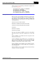
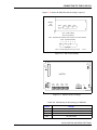
Figure 2-1 shows the correct dipswitch and jumper settings for
the CTI Intellicon serial card.
SERIAL AND PARALLEL PORTS
2-6
I-E97-811-1C
INSTALLING ADAPTER CARDS
SW1
1
8
1
SW2
J2
1
5
4
J1
1
6
SW1
On/Closed
I/O Base
* * * * * *
* *
1
SW2
On/Closed
2
3
4
5
6
7
*
* *
1
8
J2
2
*
3
SEG
4
J1
IRQ
1
2
3
4
5
1
2
3
4
5
6
GS960528
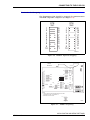
Figure 2-1. CTI Intellicon Serial Card Switch Settings
NETWORK CARDS
Ethernet Network Card
If you are setting up an Ethernet network, you will need one
card for each computer connected to the network.
You will need to record the Ethernet address and keep track of
the computer it is in. Use copies of the form supplied as Appendix B. The Ethernet's 12 digit address can be found on a label
on the card or can be displayed using the card's DOS based
software utilities. Refer to Figure 2-2.
Diskless Clients require different hardware settings than those
of Servers and Clients with disks.
HP On-Board Ethernet
The HP XU and XM series of computers have a built in ethernet
adapter. This adapter is supported for use in the LAN-90 PCV
system. This adapter is NOT support for use with a diskless
Clients.
To configure the adapter, you must use the ROM BIOS setup
provided by HP. On boot up, the “System Hardware Test”
screen will show the progress of the BIOS as it checks the computer's hardware.
•
I-E97-811-1C
Press <F2> on this screen to enter the setup screen.
NETWORK CARDS
2-7
INSTALLING ADAPTER CARDS
®
•
Locate the entry for the PCI Integrated Ethernet Interface,
refer to the computer's User's Guide.
•
Enable the PCI Integrated Ethernet Interface.
•
Press <F3> to save the change, exit the setup program and
reboot the computer.
•
When the computer reboots, the unique PCI Integrated
Ethernet Interface address will be enabled and displayed.
For the XU series you must return to the page in the setup
menu where you enabled the interface. For the XM series,
it is displayed on the summary of the computer's hardware.
Record this address in the Network Planning form.
When you install both the QNX Operating System and later on
the LAN-90 PCV software, selected the NE2100 Ethernet
driver. Using the NE2100 ethernet driver will not require an
entry for the IRQ or I/O address.
WinStar-16
The WinStar-16 is an ISA bus, NE1000/NE2000 compatible
ethernet card. All configuration settings are done using a DOS
based setup program supplied with the card. Refer to the WinStar-16 manual for details on the various settings. Using the
following procedure to start the DOS based setup program to
configure the WinStar-16 Ethernet card as shown in Table 2-8.
NETWORK CARDS
2-8
•
Boot the PC into DOS
•
Place the WinStar-16 Utility disk in the floppy drive
•
Enter the command: a:\WSPNP
•
Select the menu item View Current Configuration from the
Main Menu
•
Record the Ethernet address in Appendix B for this node
•
Verify the ethernet's card settings as listed in Table 2-8. If
they do not match, then return to the Main Menu and
select the menu item Setup WINSTAR-16 and modify the
configuration accordingly.
I-E97-811-1C
INSTALLING ADAPTER CARDS
Table 2-8. WinStar-16 Configuration
Recommended Settings
Option
Operating Mode
Address1
Server or
Client-with-Disk Node
Jumperless
Diskless Node
Jumperless
*************
*************
Medium Type2
Auto Detect
Auto Detect
Full-duplex
Disabled
Disabled
340h
340
Ethernet
I/O
Base3
Interrupt4
10
10
Boot ROM
No Boot ROM
C800, 16K
Notes:
1. The 12 digit ethernet address is unique per card.
2. The card's firmware will automatically detect the type of cable connected to the card. You can also specifically select either 10BaseT or
10Base2.
3. Alternative I/O Base addresses available are 320 and 360. Before using address 360, check that the parallel port is not assigned to address 378.
4. Alternative Interrupts are 5 and 11. Before using interrupt 11, check that your PC is not using a SCSI controller.
ALTA EtherCombo-16 T/C
The ALTA is an ISA bus, NE1000/NE2000 compatible ethernet
card. All configuration settings can be done using either the
provided DOS based utility program or jumpers (Figure 2-2), it
is recommended that the jumpers be used to configure the
card. The recommended jumper settings are listed in
Table 2-9. The DOS based utility program supplied with the
card also provides a number of diagnostics. Refer to the ALTA
EtherCombo-16+ T/C manual for details on the various
jumper settings and diagnostics.
LEGEND
J2 J3 J4 J5 J6 J7
J1
= OFF
= ON
J9 J10 J11
J8
J12 J13 J14
J15J16
Boot PROM Socket
Ethernet Address
GS960516
Figure 2-2. Alta Ethernet Network Card Settings
I-E97-811-1C
NETWORK CARDS
2-9
INSTALLING ADAPTER CARDS
®
Using the following procedure to start the DOS based setup
program to configure the ALTA EtherCombo-16 T/C Ethernet
card as shown in Table 2-9.
•
Boot the PC into DOS
•
Place the ALTA EtherCombo-16+ T/C Utility disk in the
floppy drive
•
Enter the command: a:\ALTA
•
When the Software Configuration menu is displayed, press
<Enter>.
•
Record the Ethernet address in Appendix B for this node
•
Verify the Ethernet's card settings as listed in Table 2-9. If
they do not match, then exit the program, power down the
PC and check the jumpers.
Table 2-9. ALTA EtherCombo-16 T/C Configuration
Recommended Settings
Server or
Client-with-Disk Node
Option
Value
Configuration Mode
Cabling
Type1
Address2
Diskless Node
Jumpers
Value
Jumpers
Hardware
J1 = OFF
Hardware
J1 = OFF
BNC
J2 + J3 =ON + OFF
BNC
J2 + J3 =ON + OFF
C800h
J5 + J6 =OFF + OFF
C800h
J5 + J6 =OFF + OFF
ROM State
Disabled
J7 = OFF
Enabled
J7 = ON
Access Mode
I/O Port
J8 = OFF
I/O Port
J8 = OFF
340h
J9 + J10 + J11 = OFF 320h
+ ON + ON
J9 + J10 + J11=
ON + OFF + ON
IRQ Settings 4
10
J12 + J13 + J14 =
OFF + OFF + ON
10
J12 + J13 + J14 =
OFF+ OFF + ON
8/16 Bit Mode
16 Bit
J15 = ON
16 Bit
J15 = ON
Bus Timing
CHRDY
J16 = OFF
CHRDY
J16 = OFF
ROM
I/O Base
Address3
Notes:
1. You must specifically select either UTP (10BaseT, using RJ-45 connectors) or BNC (10Base2).
2. Although the Boot ROM is disabled, do not use address D000h. We have found the Boot ROM if installed on the cards will sometimes
interfere with the CTI card even though the Boot ROM is disabled. Alternative ROM addresses available are C800h or D400h.
3. Alternative I/O Base addresses available are 320 and 360. Before using address 360, check that the parallel port is not assigned to address 378.
4. Alternative Interrupts are 5 and 11. Before using interrupt 11, check that your PC is not using a SCSI controller.
Arcnet Network Card
If you are setting up an Arcnet network, you will need one card
for each computer connected to the network.
Change the dip switches to set the ROM address to CE00 from
DC00 to avoid conflicts with the CTI Intellicon card.
NETWORK CARDS
2 - 10
I-E97-811-1C
INSTALLING ADAPTER CARDS
The card has a dipswitch in the upper left corner of the card as
shown in the Figure 2-3.
On cards with a 12 position switch, you will need to change
switches 4, 5, and 6 to 1, 0, 0 as shown in Figure 2-3.
On cards with a 4 position switch, the switch should be set to
1,0,0,1 and the IRQ must also be set to 7 using the jumpers. If
a conflict occurs between the network card and the printer
port, use interrupt 5.
1
12
SW1
SW1 On/Closed
4 Position Switch: *
*
* *
1
2
3
4
SW1 On/Closed
12 Position Switch:
*
1
* *
2
3
*
4
*
*
5
6
*
*
7
8
*
9
*
1
0
* *
1
1
1
2
GS960710
Figure 2-3. QNX Arcnet Network Card Settings
Both cards contain firmware switches that must be set
through a configuration program at boot-up time. See CONNECTING THE COMPUTER TO THE NETWORK in Section 4
for instructions. Configuring a Diskless Client is also covered
there.
ADAPTEC 1540B/1542B SCSI HOST ADAPTER CARD
Make the following changes to the Adaptec 1540B/1542B SCSI
Host Adapter card jumper to allow the SCSI card to interface to
the Optical Disk Drive only.
I-E97-811-1C
•
You MUST disable BIOS control on the card by removing
the jumper from pin 1 on J6.
•
Change the I/O Port setting from 330 to 234 by moving the
jumper from pin 2 to pin 3 on J7. This prevents conflicts
with the CTI Intellicon serial card.
•
If you are using the AHA-1542B, disable the floppy disk
controller on the Adaptec card by removing the jumper
ADAPTEC 1540B/1542B SCSI HOST ADAPTER CARD
2 - 11
INSTALLING ADAPTER CARDS
®
from pin 1 on J8. This will allow the computer's regular
floppy disks to work properly.
Figure 2-4 shows the final settings for the card.
13
1
J5
1
1
J6
8
J7
5
1
J8
8
J9
14
1
J5
1
J6
2
3 4 5 6 7 8
J7 (AHA-1542B only)
9
1
2
8
3
4
5
6
7
10 11 12 13
1 2 3
J8 (AHA-1542B only)
1
2
3
4
5
6
7
4
5
8
J9
1
2
3
4
5
6
7
8
9
10 11 12 13 14
GS960517
Figure 2-4. Adaptec SCSI Host Adapter Card
•
Make these additional changes if the Adaptec 1540B/
1542B SCSI Host Adapter also interface to the hard disk:
•
If you are using a SCSI controller hard disk, J6 pin 1 must
be installed for BIOS control.
•
Also Change the ROM address to CC00 by adding a Jumper
to J7 (7), pin 7 and remove the jumper from pin 8, if any.
ADAPTEC SCSI HOST ADAPTER CARD: MODEL 1540C/1542C/1542CF
The Adaptec SCSI Adapter card has divided its configuration
options between physical dipswitch settings and a group of
software set-up menus.
The following settings apply to the Adaptec 1540C/1542C and
1540CF/1542CF SCSI cards interfacing to only the hard disk.
Changes in these settings are noted if the SCSI card interfaces
to the Optical disk drive only, with the hard disk being interfaced to by another type of disk controller (i.e. IDE).
Dipswitch Settings
Make the following changes to the Adaptec SCSI Host Adapter
card dipswitch bank S1 before inserting it in an expansion slot.
ADAPTEC SCSI HOST ADAPTER CARD: MODEL 1540C/1542C/1542CF
2 - 12
I-E97-811-1C
INSTALLING ADAPTER CARDS
•
Change the ROM address from the factory setting to the
recommended setting as per Table 2-1. Switches 6,8
should be ON (CLOSED) and switch 7 should be OFF
(OPEN)
•
Change the I/O PORT address from the factory setting to
the recommended setting as per Table 2-2. Switch 2,3
should be ON (CLOSED) and switch 4 should be OFF
(OPEN)
•
The floppy disk option MUST be disabled by ensuring that
switch 5 is ON (CLOSED). The default setting for an
Adaptec 1542C SCSI controller is OFF (OPEN)
•
If the Adaptec SCSI Adapter card ONLY controls either an
internal hard disk or an external optical disk drive then the
AHA Termination must be enabled, set switch 1 to OFF
(OPEN) to allow the termination to be controlled by the software set-up menus.
SW1
SW1
Off/Open
*
1
* *
2
3
*
4
*
5
* *
6
7
*
8
GS960518
Figure 2-5. Adaptec 1540C/1542C SCSI Host Adapter Card
Software Set-up
The software set-up menus are viewed by rebooting the PC into
DOS, during the reboot procedure a heading will appear on the
monitor requesting the user to press <Ctrl-A> to access the
set-up menus.
The Host Adapter Port Address menu shows a list of all the I/O
PORT addresses available, with a highlight bar on the I/O
PORT address selected by the dipswitches. Press <Enter> to
select the correct Port Address.
I-E97-811-1C
ADAPTEC SCSI HOST ADAPTER CARD: MODEL 1540C/1542C/1542CF
2 - 13
INSTALLING ADAPTER CARDS
®
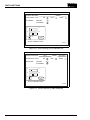
Adaptec AHA-1540C/1542C SCSI Select (TM) Utility v1 01
* If you have only one AHA-1540C/1542C
Host Adapter, press <ENTER>
* For multiple host adapter, move the
cursor to the Port Address of the one
to be configured and press <ENTER>
<F5> - Toggle color/monochrome
<ESC> - EXIT Utility
Host Adapter
PORT ADDRESS
130
124
230
234
330
334
Arrow keys to move cursor, <ENTER> to select option, <ESC> to exit
(*=default)
GS960529
Figure 2-6. Adaptec 1540C/1542C SCSI Host Adapter Card
Port Address Menu
The Main Menu allows the user to access one of Configure/
View Host Adapter Settings, SCSI Disk Utilities, Host Adapter
Diagnostics.
Proceed to the Configure/View Host Adapter Settings Menu
and confirm that the settings have been made as per
Figure 2-7.
Adaptec AHA-1540C/1542C SCSI Select (TM) Utility v1 01
AHA 1540C/1542C SCSI at port 342h
Configuration
Host Adapter Interrupt (IRQ) Channel. . . . . . . . . 11
Host Adapter DMA Channel. . . . . . . . . . . . . . . 5
Host Adapter SCSI ID. . . . . . . . . . . . . . . . . 7
SCSI Parity Checking. . . . . . . . . . . . . . . . . ENABLED
DMA Transfer Rate . . . . . . . . . . . . . . . . . . 5.0 MB/SEC
Host Adapter SCSI Termination . . . . . . . . . . . . Press <ENTER>
SCSI Device Configuration . . . . . . . . . . . . . . Press <ENTER>
<F6> - Reset to Host Adaper Defaults
BIOS INFORMATION
REVISION. . . . . . . . . .1.01
BASE ADDRESS. . . . . . . .CC00h
FIRMWARE INFORMATION
REVISION. . . . . . . . . .01
CHECKSUM. . . . . . . . . .A3C2h
Arrow keys to move cursor, <ENTER> to select option, <ESC> to
exit (*=default)
GS960530
Figure 2-7. Adaptec 1540C/1542C SCSI Host Adapter Card
Configure/View Host Adapter Settings Menu
ADAPTEC SCSI HOST ADAPTER CARD: MODEL 1540C/1542C/1542CF
2 - 14
I-E97-811-1C
INSTALLING ADAPTER CARDS
NOTE: The “Host Adapter SCSI Termination” should be DISABLED
if the SCSI card interfaces to both the internal hard disk and external
optical disk drives.
From the Configure/View Host Adapter Settings Menu, proceed to the SCSI Device Configuration sub-menu and confirm
for SCSI Device ID's #0 to #7 that the settings have been made
as per Figure 2-8.
Adaptec AHA-1540C/1542C SCSI Select (TM) Utility v1 01
AHA 1540C/1542C SCSI at port 342h
Configuration
Host Adapter Interrupt (IRQ) Channel. . . . . . . . . 11
Host Adapter DMA Channel. . . . . . . . . . . . . . . 5
SCSI DEVICE CONFIGURATION
Host Adapter SCSI ID. . . . . . . . . . . . . . . . . 7
SCSI DEVICE
#0
#1
#2
#3
#4
#5
#6
#7
SCSI Parity Checking. . . . . . . . . . . . . . . . . ENABLED
ENABLED SYNC NEGOTIATION no
no
no
no
no
no
no
no
DMA Transfer
Rate . . . yes
. . . yes
. . . yes
. . . yes
. . . yes
. . . yes
5.0 MB/SEC
ENABLED
DISCONNECTION
yes
yes
Options listed below have NO EFFECT if the BIOS is disabled
Host Adapter SCSI Termination . . . . . . . . . . . . Press <ENTER>
SEND
UNIT
COMMAND no. . .
no. . .
no. . .
no. . .
no. . Press
no
no
no
SCSISTART
Device
Configuration
<ENTER>
<F6> - Reset to Host Adaper Defaults
BIOS INFORMATION
REVISION. . . . . . . . . .1.01
BASE ADDRESS. . . . . . . .CC00h
FIRMWARE INFORMATION
REVISION. . . . . . . . . .01
CHECKSUM. . . . . . . . . .A3C2h
Arrow keys to move cursor, <ENTER> to select option, <ESC> to
exit (*=default)
GS960531
Figure 2-8. Adaptec 1540C/1542C SCSI Host Adapter Card
SCSI Device Configuration Menu
Press <Esc> to return to the Configure/View Host Adapter Settings Menu.
From the Configure/View Host Adapter Settings Menu, proceed to the Advanced Configuration Options sub-menu and
confirm that the settings have been made as per Figure 2-9.
I-E97-811-1C
ADAPTEC SCSI HOST ADAPTER CARD: MODEL 1540C/1542C/1542CF
2 - 15
INSTALLING ADAPTER CARDS
®
Adaptec AHA-1540C/1542C SCSI Select (TM) Utility v1 01
AHA 1540C/1542C SCSI at port 342h
Configuration
Host Adapter Interrupt (IRQ) Channel. . . . . . . . . 11
Host Adapter DMA Channel. . . . . . . . . . . . . . . 5
ADVANCED CONFIGURATION OPTION
Host Adapter SCSI ID. . . . . . . . . . . . . . . . . 7
Host Adapter BIOS (Configuration Utility Reserves BIOS Space). . ENABLED
SCSI Parity Checking. . . . . . . . . . . . . . . . . ENABLED
System Boot (INT 19H) Controlled by Host Adapter BIOS. . . . . ENABLED
Extended
BIOS Translation
. .MB/SEC
DISABLED
DMA Transfer
Rate . . .for
. .DOS
. .> .1G. .. .. .. .. .. .. .. .. .. .5.0
Support Removable Disks Under BIOS as Fixed Disks. . . . . . . DISABLED
Host Adapter SCSI Termination . . . . . . . . . . . . Press <ENTER>
Dynamically Scan SCSI Bus for BIOS Devices . . . . . . . . . . DISABLED
BIOS
Support
more than 2 .Devices
(MSDOS
. <ENTER>
DISABLED
SCSI
Devicefor
Configuration
. . . .
. . .5.0
. .or. greater).
. . . Press
Immediate Return on Seek Command . . . . . . . . . . . . . . . ENABLED
<F6> - Reset to Host Adaper Defaults
BIOS INFORMATION
REVISION. . . . . . . . . .1.01
BASE ADDRESS. . . . . . . .CC00h
FIRMWARE INFORMATION
REVISION. . . . . . . . . .01
CHECKSUM. . . . . . . . . .A3C2h
Arrow keys to move cursor, <ENTER> to select option, <ESC> to
exit (*=default)
GS960601
Figure 2-9. Adaptec 1540C/1542C SCSI Host Adapter Card
Advanced Configuration Options Menu
Press <Esc> to return to the Configure/View Host Adapter Settings Menu.
NOTE: The “System Boot (INT 19H) Controlled by Host Adapter
BIOS” should be DISABLED if the SCSI card interfaces to the Optical disk drive only.
Both the “Dynamically Scan SCSI Bus for BIOS Devices” and the
“BIOS support for more than 2 devices” should be ENABLED if
the SCSI card interfaces to the optical disk drive only.
MKM/EMKI KEYBOARD SWITCHING
If you are installing an MKM or EMKI keyboard, you can set up
two computers on the QNX network so that the one keyboard can
be used to operate both computers. This lets operators watch and
use two displays, such as a process graphic and the alarm summary, at the same time by switching the MKM or EMKI keyboard
input between the two computers (indicators on the screen tell
the operator which computer is the active console). Set the two
computers so that their monitors can be placed close together.
Attach the MKM/EMKI keyboard to one computer. The computer
with the MKM/EMKI keyboard is called the main keyboard node;
the other computer is called the auxiliary keyboard node. Connect both computers to the network. Further steps are needed to
enable the MKM/EMKI keyboard switching, and these are discussed in Section 9.
MKM/EMKI KEYBOARD SWITCHING
2 - 16
I-E97-811-1C
SECTION 3 - CONNECTING PERIPHERAL DEVICES
OVERVIEW
This section covers the procedures for connecting the following
peripheral devices:
•
•
•
•
•
•
•
Monitors
Pointing Device
Operator Keyboards
Annunciator Display Panels
Printers
Security Key
Optical Disk Drives
For peripherals not covered in this section, contact your nearest Elsag Bailey Service Centre.
MONITORS
Connect the monitor to the output from the video card.
Second Monitor
If you are installing an MKM or EMKI operator keyboard, you
can use one operator keyboard to operate two monitors. The
monitors, however, are attached to different computers, which
are connected by the network. See Section 4, for details.
POINTING DEVICES
LAN-90 PCV console software uses a pointing device to move a
pointer/arrow across the screen. Normally the pointing device
is either a two or three button mouse. As an option a Trackball
can be used instead of the mouse.
Both the left and right hand buttons on the mouse or trackball
are used for specific functions by the LAN-90 PCV console.
Left Button
Pressing the left button while on a menu or icon button will
activate the menu or icon button function.
Right Button
Pressing the right button while on a menu or icon button will
cause a sub-menu to be displayed, if it exists.
CAUTION
I-E97-811-1C
Do not attach the pointing device with the power on the PC.
OVERVIEW
3-1
CONNECTING PERIPHERAL DEVICES
®
OPERATOR KEYBOARDS
Operator or mylar keyboards can be connected to LAN-90 PCV
consoles. These keyboards have a flat panel surface that is
resistant to spills and dirt. The panel surface can be produced
with standard keys or with specialized keys. These keyboards
are built into Elsag Bailey industrial consoles.
In order to use these keyboards with a standard PC, the keyboards require their own power and a special interface to the
PC. The interface and the power are contained in a separate
interface box. Mylar keyboards attach to the interface box
which is attached to a serial port on the PC.
CAUTION
Do not attach the keyboards with the power on.
There are two different interface boxes: the MKI and the EMKI.
There are three different main keyboards: N90, I90 and OIS as
well as an auxillary ADS panel. The Nema 4 standard PC style
(QWERTY) keyboard is installed identically to any other PC
keyboard.
The MKI keyboards are flat and use a large modular (phone)
type connector. The EMKI keyboards are wedge shaped and
use a round DIN connector.
MKI Connections
C
O
N
N
E
C
T
O
R
S
[]
J4
J3
[]
J2
J1
(straight cable)
(null modem cable)
J1
or
J2
J3
1
J4
3
1
3
GS960602
Figure 3-1. IIMKM01 Keyboard Interface Board
OPERATOR KEYBOARDS
3-2
I-E97-811-1C
CONNECTING PERIPHERAL DEVICES
Connect the interface unit to the computer using a serial cable
between the J1 port on the rear face of the interface unit and
the second serial port of the computer. The serial port would
be Com2 “/dev/ser2" or the second port of the CTI Intellicon
Serial port ”/dev/cti2".
Jumper settings on the IIMKM01 keyboard interface board
inside the interface box determine whether the serial cable is
straight through or a null modem cable (Figure 3-1).
The OIS input distribution board in the front half of the box
must have all switches on switch block one (SW) set to open
(off). This selects OIS10 mode.
EMKI Connections
Connect the interface unit to the computer using a serial cable
between the J1 port on the rear face of the interface unit and
the second serial port of the computer. The serial port would
be Com2 “/dev/ser2" or the second port of the CTI intellicon
serial port ”/dev/cti2".
The serial cable is a straight through cable. A null modem is
not required.
Connect the keyboard to the interface box.
The EMK keyboard must be set to use power supplied by the
interface unit. This is the default setting. If necessary you can
verify the setting. Open up the keyboard unit and set the
jumpers on J1 to J3 to connect positions 1-2 (the pins furthest
from connector P2) Leave pin 3 bare.
P8
P7
1
J1
J3
J2
1
2
3
P2
3
J1
J3
P2
J2
GS960603
Figure 3-2. EMKI Keyboard Jumper Settings
I-E97-811-1C
OPERATOR KEYBOARDS
3-3
CONNECTING PERIPHERAL DEVICES
®
Keyboard Identification
Look on the upper left for a key labelled I90 status or N90 status. If there is no such key, assume the keyboard is an OIS
keyboard. Most standard keyboards would be I90 keyboards
while specialized keyboards would be OIS type.
Software Configuration
The keyboard will not function with LAN-90 PCV until LAN-90
PCV has been configured to use the keyboard.
From the LAN-90 PCV Main Menu, select Configuration, then
System Options, then Console Configuration.
•
Set the keyboard to one of N90, I90 or OIS.
•
Set the device to either “/dev/com2" or ”/dev/cti2"
If you are using a CTI card it too will need configuring. See
SERIAL AND PARALLEL PORTS in Section 2 of this manual.
ADP
The ADP (Annunciator/Display select Panel) connects to the
MKM interface unit or the EMKI keyboard.
CAUTION
Make sure power to the MKM or EMKI keyboard interface is
OFF before connecting the ADP. Failure to disconnect the
power from the keyboard interface may result in blown fuses or
damage to the ADP or keyboard.
For MKM keyboard systems, connect the ADP to the AUX1 port
on the front face of the MKM keyboard interface unit.
For EMKI keyboard systems, connect the ADP to either the leftmost or rightmost 15 pin connector on the rear of the keyboard. You can use either connector, but there can only be
ONE ADP connected to the keyboard at a time.
NOTE: Do NOT disconnect the ADP during operation. If disconnected, the ADP will not work until the console is restarted.
If you must disconnect an ADP, turn off the MKM/EMKI keyboard first, and only turn the keyboard back on after you have
reconnected the ADP.
OPERATOR KEYBOARDS
3-4
I-E97-811-1C
CONNECTING PERIPHERAL DEVICES
PRINTERS
The default printer is a black & white IBM graphics-compatible
printer attached to the first parallel port (“/dev/par1") of
node1.
If you are using a black-and-white GENICOM printer, make
sure it is set for IBM emulation.
If you are using a color GENICOM printer, make sure it is set
for ANSI emulation mode.
You can change the printer setup after the installation. See the
Operations manual - Section 2, Printer Setup, for details.
You will need a Post-script Compatible printer attached to the
second parallel port (“/dev/par2") if you want to print screen/
window displays.
Printers can be attached to any console, then shared through
the network.
INSTALLATION OF SECURITY KEY
Included with your LAN-90 PCV software is a SentinalC-plus
Security Key to be attached to the parallel port of the console.
This device is used to identify registered copies of LAN-90 PCV.
Without the key, a pop-up window will appear once every 5
minutes declaring the software to be unregistered.
CAUTION
Before installing the security key ensure that the computer
power is off and proper static safety precautions are followed.
To install the security key, simply attach the key to the parallel
port 25 pin DIN connector at the rear of your Personal Computer. The port selected must be configured as LPT1. Tighten
the thumb-screws to secure the key and connect the printer to
the key. The SentinelC-plus security key is a passive device
which allows the parallel port to functions normally.
NOTE: A hardware conflict may exist between the LPT1 parallel port
and an NE2000-compatible Ethernet card if the card has been configured to use the 360-3ff I/O port range. By default, the LPT1 parallel port is configured to reside at ports 3f8-3ff (within the 360-3ff
range). If this is the case, either an alternate address will have to be
used for the ethernet card or the parallel port must be changed in
the BIOS to use addresses 2f8-2ff (normally used for LPT2, in which
case if there is a second parallel port on the computer, it should be
disabled).
I-E97-811-1C
PRINTERS
3-5
CONNECTING PERIPHERAL DEVICES
CAUTION
®
Before connecting a printer to the security key ensure the
power to the printer is turned off.
OPTICAL DISK
Set the SCSI address of the optical drive with the pushbuttons
on the back of the drive. The SCSI address you set for the drive
must differ from any other SCSI device attached to the computer. You will probably set an address of 2 (two), if this is the
only device on the SCSI bus.
Connect the optical drive to the Adaptec SCSI Host Adapter
card using a SCSI cable.
Follow the manufacturer's instruction (supplied with the optical drive) regarding the use of special terminators.
Optical disks are removable hard drives. With LAN-90 PCV
they can be used as archive devices or as standard drives for
manual or automatic backup purposes.
When your hard drive is a SCSI, the drive will automatically be
available to the system for archive purposes. It will not be
available for backup unless you configure LAN-90 PCV. When
your hard drive is an IDE or you will be using the drive as a
QNX file system (for backups) then you will need to configure
LAN-90 PCV. To configure LAN-90 PCV; from the Main Menu,
choose Configuration, System Options, Console Configuration
and set the optical disk as installed. If there is only one optical
on this computer select “/dev/hd2". At this release LAN-90
PCV does not support more than one optical drive per computer at a time. If you have more, you may make any one, but
only one as active.
Pushbuttons
2
Rear of Optical Drive
A B C D E
F G H
1
0
* * * * * * * *
Dipswitches
GS941208
Figure 3-3. Optical Drive Address Setting
OPTICAL DISK
3-6
I-E97-811-1C
CONNECTING PERIPHERAL DEVICES
Since optical drives are standard drives, they can be partitioned. LAN-90 PCV assumes that the QNX partition is always
the first partition. If the first or only partition is a DOS partition then LAN-90 PCV will report that there is no room on the
partition.
To verify the optical hardware is working on a newly installed
LAN-90 PCV system, first select the Main Menu, choose Configuration, then System Options, Console Configuration and set
or verify that the optical disk is installed. Shutdown and
reboot if you needed to change the configuration. From the
Main Menu, choose Utilities, then Misc Disk Utilities and if the
disk is formatted use Media Usage and Contents, F1 Usage. If
you get a report on free and available space your drive is working. If the disk is new, choose Format/Initialize Media, F1 Format. After one to two minutes the utility will report free space.
If you formatted, this disk is formatted for QNX.
Backup Usage
The backup and restore utilites use the optical as a QNX disk.
Use the Misc Disk Utilities to initialize disks for backup.
I-E97-811-1C
OPTICAL DISK
3-7
SECTION 4 - LAN-90 PCV NETWORKING
SETTING UP THE NETWORK
The LAN-90 PCV software has been designed to work in both
the one node standalone environment and a multiple node
local area network (LAN) environment. The QNX Operating
System upon which the LAN-90 PCV software has been based
supports the both the Ethernet and Arcnet types of network
communication protocols.
ETHERNET SETUP
An Ethernet network can use a combination of different types
of network cards, cables and other hardware. NETWORK
CARDS in Section 2 of this manual describes the configuration
of the currently supported Ethernet network cards for the
LAN-90 PCV console network.
The two most common types of ethernet network cables (or
communication media) are 10Base2 (also referred to as BNC or
coax) and 10BaseT (also referred to as twinax or twisted pair).
These two methods of cabling nodes together can be combined
by use of mutiport concentrators.
Ethernet networks are also commonly used in office networks,
however, it is recommended that the LAN-90 PCV network be
isolated from the office network by means of a bridge due to
the amount of traffic generated by the nodes within the
LAN-90 PCV network.
10Base2 Network
In order to use 10Base2 cables for the LAN-90 PCV network it
is necessary that the correct type of cable (RG-58), terminators
(50 ohm), connectors ("T") be used. Figure 4-1, illustrates a
basic 10Base2 network of LAN-90 PCV nodes.
I-E97-811-1C
•
here are also other standard ethernet limitations to be
aware of, such as:
•
a BNC "T" connector must be used to attach each nodes
network card to the segment
•
the maximum length of a segment is 185 meters
•
the minimum length of cable between two nodes is 0.5
meters
SETTING UP THE NETWORK
4-1
LAN-90 PCV NETWORKING
®
•
each end of a segment must be terminated with a 50 ohm
terminator
•
a maximum of 29 nodes (or adapters) can be attached to a
single segment, the repeater counts as the 30th node
•
segments can be connected together by use of repeaters
•
a maximum of 4 repeaters can be used to extend the total
LAN length to 1000 meters
•
the maximum number of nodes is 1024
LAN-90 PCV
Client
LAN-90 PCV
Client
LAN-90 PCV
Client
N-90
LA
N-90
LA
N-90
LA
N-90
LA
GS960715
LAN-90 PCV Server
N-90
LA
LAN-90 PCV Server
Figure 4-1. Sample 10Base2 Network
10BaseT Network
In order to use 10BaseT cables for the LAN-90 PCV network it
is necessary that the correct type of cable (UTP), repeater
(HUB), connectors (RJ-45) be used. Figure 4-2, illustrates a
basic 10BaseT network of LAN-90 PCV nodes. There are also
other standard ethernet limitations to be aware of, such as:
ETHERNET SETUP
4-2
•
each node must be connected to a repeater using a cable
segment
•
the maximum length of a segment is 100 meters
•
a maximum of 29 nodes (or adapters) can be attached to a
single segment, the repeater counts as the 30th node
•
segments can be connected together by use of repeaters
I-E97-811-1C
LAN-90 PCV NETWORKING
•
maximum of 4 repeaters can be used to extend the total
LAN length to 1000 meters
•
the maximum number of nodes is 1024
10BaseT Repeater
N-90
LA
N-90
LA
LAN-90 PCV Server
LAN-90 PCV Server
N-90
LA
N-90
LA
LAN-90 PCV Client
LAN-90 PCV Client
GS960716
Figure 4-2. Sample 10BaseT Network
ARCNET SETUP
Network setup and cabling information is also covered in your
QNX4 User's Guide manual, Section 5 - Network Installation.
Cables
The recommended Arcnet cable is RG62/U, 93 ohm coax, terminated with BNC male connectors.
Network cables must be routed so that they will not be
crushed, severed, exposed to excessive heat, or bent (causing
permanent kinks).
Cables can be up to 2000 feet long.
Hubs
The active hub (ARC-208) is an eight port, externally powered
hub that allows eight network cables to be connected. The
active hub regenerates even highly degraded signals received
from one port, and repeats it, completely restored, at the other
seven ports.
I-E97-811-1C
ARCNET SETUP
4-3
LAN-90 PCV NETWORKING
®
You do not need an active hub if your network only consists of
two computers that are closer together than 2000 feet.
You will need an active hub if your network consists of two
computers that are farther apart than 2000 feet or if your network consists of more than two computers.
The active hub must be plugged into a 110V/60Hz power supply. Make sure that power is available at the site for the active
hub when you lay out your network.
To connect a network cable to the port on a hub, simply push
the cable connector onto the port connector, then turn the
cable connector clockwise until it locks.
You can connect and disconnect network cables from the
active hub at any time without affecting the rest of the network
(however, you will interrupt the communication to/from the
disconnected console).
CONNECTING THE COMPUTER TO THE NETWORK
To connect a computer to the network, you must:
1. Configure the ARCnet Network card.
2. Connect a network cable to the card.
NOTE: Do NOT connect the network cable to the network card, until
after you configure the card as described below.
Configuring the ARCnet Network Card
Before connecting each computer to the network, you must
configure each computer's network card with the correct information via a menu. To call up this menu:
1. Start up your computer <Ctrl><Alt><Shift><Del>.
2. As soon as you see the message Node ## displayed in the
center of your screen, press <Esc>.
3. You will see the following menu displayed on the screen:
Node ##
N Boot from Network.
D Boot from Disk.
Enter “N” or “D”.
Press <Esc> again (ignore the prompt to Enter “N” or “D”).
CONNECTING THE COMPUTER TO THE NETWORK
4-4
I-E97-811-1C
LAN-90 PCV NETWORKING
4. You will see the QNXnet Network Interface Configuration
Menu displayed on the screen.
Make sure that the network card settings match those listed in
Table 4-1. The menu selections displayed may differ slightly
from those listed in Table 4-1 depending on the version of network card you are using.
Table 4-1. Network Card Menu Settings
Type of Node
Menu Field
1. Boot from Boot Node1
2. Local Node ID
3. Boot Node ID
4. Alternate Boot Node ID
5. Retries from Boot Node
6. Boot Filename
7. Hardware Interrupt Level
Client
Server-Client or
Stand-Alone
Diskless
Client
No
1-254
0
0
0
7
Yes
1-254
1
2
3
7
1
An Arcnet network can have only one Boot Node to service Boot request from Diskless
Clients.
To change a menu setting, press the number displayed to the
left of the setting, type the new setting, then press <Enter>.
The manual provided with the card fully describes the purpose
of all settings and Table 4-2 provides a summary.
When you have set all the necessary items in the menu, select
the option Exit Menu And Boot, and the computer will restart
with the new settings.
Table 4-2. Arcnet Network Card Settings
Field
Boot
from Network
Network
Card Version
all
Local Node ID
Boot node ID
or Primary Boot
node ID
Explanation
If this is set to NO, the computer will start up (boot) from its own hard
disk as is normally done without a network card. Only diskless clients set
this to YES and the computer will use files on the Boot node to load the
operating system.
This number must be unique for each computer on the network. Valid
numbers are 1-254.
all
This specifies the node number of the computer that is acting as the
Boot node. This setting is used only by diskless clients.
All other computers set to zero.
Alternate
Boot Node ID
2.2
and later
This specifies an alternative node number to boot from if the regular
Boot node is unavailable (e.g., it has been disconnected or turned off).
Retries from
Boot Node
2.4
and later
This specifies the number of times this node will try to boot from the regular Boot node, before using the Alternate Boot node.
Boot filename
I-E97-811-1C
all
Leave Blank.
CONNECTING THE COMPUTER TO THE NETWORK
4-5
LAN-90 PCV NETWORKING
®
Table 4-2. Arcnet Network Card Settings
Field
Network
Card Version
Software
Interrupt Level*
2.2
and later
2.1
and earlier
(continued)
Explanation
This specifies the hardware interrupt used by the card. For QNX Network card versions 2.2 and later, the default value is set to 7 and this is
the setting you should normally use. For QNX Network card versions 2.1
and earlier, the hardware interrupt is set with a jumper on the card itself,
and you enter the interrupt number set by the jumpers on the card. The
default value for network card versions 2.1 and earlier is 2, and you
MUST change this to 7.
The default value is 7 and must NOT be changed.
* If a conflict occurs between the printer port and the network card, use Interrupt 5.
CONNECTING THE COMPUTER TO THE NETWORK
4-6
I-E97-811-1C
SECTION 5 - CONNECTING TO THE ICI OR CIU
OVERVIEW
The LAN-90 PCV console communicates with the INFI 90
OPEN or Network 90 system through the INFI 90 OPEN Computer Interface (ICI) or through the Computer Interface Unit
(CIU).
There are two basic versions of CIU, the first version is for use
on Elsag Bailey systems using Plant Loop communication, the
second version is for use on Elsag Bailey systems using
INFI-NET communication.
The ICI is made up of two modules:
•
INNIS01 (Network Interface Slave)
•
INICT01 (INFI-NET to Computer Transfer Module) or
INICT03 (added functionality over INICT01)
The INFI-NET type of CIU is made up of two modules:
•
•
NLIS01 (Loop Interface Slave)
NSSM01 (SuperLoop Slave Module)
The Plant Loop type of CIU is made up of three modules:
•
•
•
NLIM01 (Loop Interface Module)
NBTM01 (Bus Transfer Module)
LSM (Loop Storage Module)
Both the ICI and CIU connect to the Termination Unit,
NTMF01, using the cable NTKU01.
NOTE: If using the INICT03 replace the NTMF01 with NTMP01 and
replace the NKTU01 cable with NKTU02 cable.
This section only describes the module settings to use with
LAN-90 PCV. For complete information on these modules refer
to the INFI-NET Communications Modules manual (Product
Instruction) or the NCIU02/03 Enhanced Computer Interface Unit manual (Product Instruction).
ICI/CIU SWITCH AND STRAP SETTINGS
ICT/SSM/LSM Switch Settings
Set the ICT, SSM, or LSM for:
•
I-E97-811-1C
ROM checksumming ON
OVERVIEW
5-1
CONNECTING TO THE ICI OR CIU
®
•
8 data bits, 1 stop bit, no parity
•
All ports act as serial ports for connection to a host computer
•
Modem password protection OFF
•
Port addressing OFF
•
Checksumming ON
•
Primary LSM
•
9600 baud or 19200 baud (see Table 5-1)
Figure 5-1 shows the ICT/SSM/LSM switch settings required.
INNICT01
NSSM01
OR NLSM01
U72
1
U75
1 8
U73
1
8
8
U72 - Options
2 3 4 5 6 7
1
8
* * * * * * * *
Open/Off
1
*
U73 - Baud Rate
9600 baud
2 3 4 5 6 7
* * *
*
8
* * *
Open/Off
1
U73 - Baud Rate
19200 baud
2 3 4 5 6 7
8
* * * * * * * *
Open/Off
5 - Port Addressing, any setting: port addressing is turned off.
GS960604
Figure 5-1. ICT, SSM, or LSM Settings
Table 5-1. ICI/CIU Baud Rate Settings
Type of Serial Card
Installed in Computer
Baud Rate Setting for the
ICT, SSM, or LSM
Regular Serial Card
9600 baud
CTI Intellicon Serial Card
19200 baud
NIS/LIS Switch Settings
Set the NIS or LIS for:
•
•
•
PCU or ICI network processing compatibility
ROM checksumming ON
Normal operating mode
ICI/CIU SWITCH AND STRAP SETTINGS
5-2
I-E97-811-1C
CONNECTING TO THE ICI OR CIU
Figure 5-2 shows the NIS/LIS switch settings required.
INNIS01
OR
NLIS01
SW4
SW3
1
SW2
SW1
8
SW1 - Node Address
SW2 - Ring Address
SW4 - Expander Bus Address and Event/Error Counters Address
SW3 - Operations Modes
1 2 3 4 5 6 7 8
Open/Off
SW3 - 7/8 setting depends on type of loop
GS960606
Figure 5-2. NIS or LIS Settings
P5
J5
MOD B
J4
30V
INICT03
J1
P4
SW4
UUB0
SW1
UMB1
SW2
LMB2
1 2 34 56 78
OPEN
12345678
OPEN
12 3 4 5 67 8
OPEN
SW5
HW SETUP
SW3
LLB3
J2
2
143
1 2 3 4 5 6 78
OPEN
GS960607
Figure 5-3. INICT03 Switch Settings
Table 5-2. Mandatory Switch Settings for INICT03
I-E97-811-1C
Switch
Settings
SW1
All poles open (19200 baud)
SW2
All poles closed
SW3
Poles 1 to 4 closed; Poles 5 to 8 open
SW4
All poles closed
ICI/CIU SWITCH AND STRAP SETTINGS
5-3
CONNECTING TO THE ICI OR CIU
®
LIM Switch Settings
Set the Loop Interface Module (LIM) to transmit total messages,
including forwarding (see Figure 5-4).
SW1
1
SW2
8
SW1 - Options
2 3 4 5 6 7
1
8
Open/Off
SW2 - PCU Address
GS960608
Figure 5-4. LIM Settings
BTM Switch Settings
Set the Bus Transfer Module (BTM) for normal operation (see
Figure 5-5).
SW1
1
1
5
SW1
2 3 4 5
Open/Off
GS960609
Figure 5-5. BTM Settings
ICI/CIU SWITCH AND STRAP SETTINGS
5-4
I-E97-811-1C
CONNECTING TO THE ICI OR CIU
Termination Unit Strapping
The Termination Unit should be strapped for communication
with IBM-compatible computers (see Figure 5-6).
DTE
XU2
DTE
XU1
20
19
18
17
16
15
14
13
12
11
1
2
3
4
5
6
7
8
9
10
20
19
18
17
16
15
14
13
12
11
1
2
3
4
5
6
7
8
9
10
GS960610
Figure 5-6. NTMF01 Dipshunt Strapping
NIMP01
6638943E
6
8
P5
11 9 10 12
J6
J5
5
7
J7
J14
J1
J15
P6
11 9 10 12
J8
1
8
J18
P7
J12
J9
1
8
4
5
J10
4
5
J13
SPARE
SPARE
9 PIN
J11
P3
6
8
RS-485 PORT
1 3 4 2
J17
9 PIN
J16
PRINTER PORT
2
9 PIN
J2
1 3 4
5
7
TERMINAL PORT
LED
P1
P11
NOTES:
1. J1 AND J2 SELECTS THE INTERFACE MODE OF THE MFP.
J1 CONTROLS P6 AND J2 CONTROLS P5.
CONFIGURE J2 AS FOLLOWS:
J2
1 3 4 2
5
7
6
8
11 9 10 12
GS960611
Figure 5-7. NIMP01 Jumpering
I-E97-811-1C
ICI/CIU SWITCH AND STRAP SETTINGS
5-5
CONNECTING TO THE ICI OR CIU
®
CONNECTING THE ICI OR CIU
A serial cable connects the terminal port of the Termination
Unit to the /dev/ser1 (COM1) or /dev/cti1 port of the CTI card
of the console (see Table 5-3).
Elsag Bailey recommends that you use isolating modems at
each end of the serial cable connecting the computer and the
ICI/CIU, to avoid groundloops between the two. Without isolating modems, it is possible for a potential difference to form
along the serial cable that could damage the computer or the
ICI/CIU.
CAUTION
NOTE: The INICT03 cannot power on isolating modem. An
externally powered isolating modem must be used with the
INICT03.
ICI
or
CIU
NTKU01
Termination
Unit
regular
IM
serial cable
IM
IM = isolating modems (recommended)
GS960612
Figure 5-8. ICI/CIU Cable Connections
Figure 5-9 shows the pin connections in both a 25 pin to 25
pin serial cable and a 9 pin to 25 pin serial cable.
9 Pin
Male
1
2
3
LAN-90 4
PCV 5
6
7
8
9
25 Pin
Female
8
OR
3
2
20 Termination
7
Unit
6
4
5
22
25 Pin
Male
2
3
4
LAN-90 5
6
PCV
7
8
20
25 Pin
Female
2
3
4
5 Termination
6
Unit
7
8
20
GS960613
Figure 5-9. Termination Unit Serial Cable
CONNECTING THE ICI OR CIU
5-6
I-E97-811-1C
CONNECTING TO THE ICI OR CIU
Table 5-3. ICI/CIU to Serial Port Connections
Type of Serial Card
Installed in Computer
Serial Port Used to Connect
to ICI or CIU
Regular serial card
/dev/ser1 (COM1)
CTI Intellicon serial card
/dev/cti1
SOFTWARE CONFIGURATION
The CIU to which the LAN-90 PCV Server console is attached
will not be on-line when the console is first rebooted after being
loaded with the LAN-90 PCV software. You must first configure
the Server by choosing Main Menu, System Options, Console
Configuration. The highlighted bar must then be moved using
the arrow keys to the node number of the Server that is connected to the CIU, then press <F2> Edit Console Options. On
the first hardware page, select the type of communication loop,
Serial driver, baud rate and Serial Device. Refer to the subsection Edit Console Configuration located in Section 2 of the
Configuration manual for details.
I-E97-811-1C
SOFTWARE CONFIGURATION
5-7
SECTION 6 - INSTALLING DOS
CONSIDERATIONS WHEN INSTALLING DOS
To have both QNX and DOS on your hard disk, you must
install DOS first, leaving enough room for QNX and LAN-90
PCV (at least 100Mb).
If your hard disk has more than 1024 cylinders, make sure
you leave space on the hard disk below 1024 for QNX. QNX
boot files must be located below cylinder 1024, otherwise QNX
cannot start up from the hard disk.
Loading Both DOS and QNX
To load both DOS and QNX on the same hard disk, you must
follow these restrictions:
•
Install DOS BEFORE you install QNX - refer to Appendix A
•
Do NOT use the entire hard disk for DOS; leave at least
200Mb available for LAN-90 PCV use.
Accessing DOS Partition from QNX
To be able to access files on your DOS partition from QNX
(such as graphic display files created with SODG), you must
set up your DOS partition the following way:
•
Set up a Primary DOS partition
•
You can set up Extended DOS partitions, and you will be
able to access any files on them from QNX
The details of creating the DOS partition depend on the version of DOS you are installing. The DOS partition is set up
using the FDISK program, which is run either as part of a DOS
installation program or from the DOS prompt.
For a complete description of how to install DOS, refer to your
DOS manuals.
It is recommended that copies of configuration utilities for the
computer, video card, and network adapter be kept on the
DOS partition. This allows system configuration to be quickly
tested.
I-E97-811-1C
CONSIDERATIONS WHEN INSTALLING DOS
6-1
INSTALLING DOS
®
ADAPTER CARD UTILITIES
Some of the adapter cards installed in the LAN-90 PCV console
(such as graphic cards, network cards) have provided a utility
or configuration disk and user's guide. These utilities should
be installed in the DOS partition of the hard disk, using the
instructions provided in the adapter card's user's guide.
ADAPTER CARD UTILITIES
6-2
I-E97-811-1C
SECTION 7 - INSTALLING QNX
OVERVIEW
LAN-90 PCV requires a real time operating system so that
more than one task can be performed at the same time. This
section covers installation of QNX, the operating system used.
A specific version of QNX is supplied with your program disks.
If you are currently running an older version, you will need to
back up your configuration. The QNX install program initializes the section of your hard drive used by the QNX operating
system. Unless you change the partition sizes, any DOS partition will remain untouched.
The network card in the computer should be reconfigured correctly, refer to Section 2.
You can upgrade your LAN-90 PCV system one computer at a
time. The entire system does not need to be shut down in order
to upgrade. However, each computer being upgraded will need
to be shut down just before it is installed. See UPGRADING in
Section 8.
INSTALLING QNX
CAUTION
If you are upgrading your LAN-90 PCV system, you must back
up your configuration and data before you begin. If you have
stored any other files, you should also back them up. LAN-90
PCV will only back up its own files. Refer to UPGRADING in
Section 8.
CAUTION
QNX must be installed on each computer on the network that
has its own hard disk.
NOTE: Diskless computers can be configured on any of the other
operator stations and do not need any installation. Refer to the Configuration manual after installing the servers and clients-with-disk.
Assumptions
1. If upgrading you must have backed up your configuration
and data.
I-E97-811-1C
OVERVIEW
7-1
INSTALLING QNX
®
2. You have the following disks:
BOOT disk
INSTALL disks
NETWORK EXPANSION
QNX WINDOWS
1 disk
3 disks
0 or more disks (if applicable)
2 disks
3. You have a Node number plan stating what node number to
use for each computer and its Ethernet address. Refer to
LICENSING later in this section for details on defining node
numbers. A sample form is provided in Appendix B.
Identifying Ethernet Addresses
The Ethernet address is twelve digits long. There are four sets
of three hexidecimal numbers. Hexidecimal numbers also use
the letters A-F as digits. An example is 00C 093 00D B4F.
Refer to the subsection Ethernet Network Card in Section 2
in this manual for the procedure to get the Ethernet card
address.
INSTALLATION
An automated install program is used to install QNX onto the
hard disk.
STEP A
Booting from the Floppy Boot Disk
•
Insert the Boot disk into the first drive (/fd/0) (A:)
•
If you are upgrading, exit LAN-90 PCV.
•
Boot from the computer. Press <Ctrl><Alt><Shift><Del>.
•
As QNX is loading you will see a spinning arrow.
•
Booting from the floppy is slow.
NOTE: The following step numbers follow the pattern used by the
automatic QNX installation program.
Step 1
Creating a QNX Hard Disk Partition
At the # prompt type:
install
QNX's hard disk installation screen is displayed.
This screen displays the QNX Technical support phone number and other miscellaneous warnings. If you require support
call your Elsag Bailey representative.
INSTALLATION
7-2
I-E97-811-1C
INSTALLING QNX
Follow the prompts which are shown below.
U.S. Keyboard:
Answer Y (U.S. keyboard is the default)
Step 1 screen is displayed
Creating a QNX Hard Disk Partition.
Value point machine:
Answer N (No is the default)
Verify hard disk type (IDE or SCSI)
1a Verify drive size (Accept defaults)
The installation program will then run either “fsys.ide” or
“fsys.scsi” device driver.
1b Query free
1c Query QNX
1d Fdisk
The fdisk hard drive partition table screen is then displayed.
If no changes are needed to the partition table press Q to quit,
otherwise, refer to the QNX documentation for a full description of the Fdisk Utility.
Step 2
Initializing the QNX File Structure
2a mount -p /dev/hd0
Warning Qnx partition found
2b dinit
2c mount hd0t77
Which test do you want?
Answer V.
I-E97-811-1C
INSTALLATION
7-3
INSTALLING QNX
Step 3
®
Copying Files from Floppy to Hard Drive.
When the Step 3 title box is displayed you will need to wait for
the disk access to complete. When the disk light goes out,
insert disk 1 and press enter. Insert disks 2 and 3 when
prompted.
Step 4
Making QNX Boot from the Hard Drive
Do you wish to install the 32 bit kernel?
Answer Y
Enter logical Node #
This is the logical node number you have assigned to your
computer. Enter the node number as per your Network Planning Form in Appendix B.
rundos
Answer N
Press <Enter> when prompted.
4b Install setup
4b1 tic /usr/lib/....
Step 5
4c
make ....
4d
cp -t ......
4e
fdisk ...
4f
fdisk ...
Create a System Initialization File
Select your time zone.
Select the time zone representing your local time.
Example U for Toronto, Canada which is in the Eastern Time
Zone.
CAUTION
Ensure that the same time zone is used on all computers.
Select time use
This specifies the time to which the battery charged hardware
clock is set. This is the clock that keeps time while the computer is turned off. Standard dedicated LAN-90 PCVcomputers
should use Global time. Global time is also called Greenwich
Mean Time or Universal Co-ordinated Time (UTC). However if
INSTALLATION
7-4
I-E97-811-1C
INSTALLING QNX
this computer is only occasionally used for LAN-90 PCV and is
mostly used for DOS applications then the clock should probably be set to local time.
Answer G - global
How many consoles would you like mounted?
Answer 6
Will you be using a mouse with this machine?
Answer Y
Step 6
Configure a Network Boot Server
Do you wish to configure this machine for use on the QNX network?
Answer Y
CAUTION
You MUST choose to make every node a “Network Boot
Server” in order for the installation program to properly configure the network.
Do you have any network expansion diskettes?
Answer Y if you have any QNX Network Expansion disks or if
you are networking more than one LAN-90 PCV Server
together, otherwise, answer N.
Prior versions of LAN-90 PCV used dedicated boot servers. The
approach used by this version is discussed in “Upgrading” in
the next section.
NOTE: If this is not a standalone machine there will be one or more
network expansion disks or set of QNX Operating System disks.
Insert network expansion licenses
Depending on your LAN-90 PCV system configuration, you
may have more than one Server and/or Client nodes. For each
Server node, a complete set of QNX O/S disks have been provided, for each Client node, a QNX Network Expansion disk
has been provided. To increase the network size, all the
INSTALL 1 disks and QNX Network Expansion disks must be
inserted into the computer, one at a time, at this point of the
installation procedure. After inserting each disk, press the
<Enter> key.
Answer No when finished.
Driver selection
I-E97-811-1C
INSTALLATION
7-5
INSTALLING QNX
®
For NE1000 or NE2000 compatible ethernet cards
choose
b - ne1000
For NE2100 compatible ethernet cards
choose
d - ne2100
NOTE: Two NE2000 error messages will be displayed at the top of
the screen. Please ignore them.
Standard arcnet choose
a - arcnet
Physical to logical mapping
For Ethernet, enter the 12 digit Physical Node Number. Refer
to the Network Planning Form in Appendix C.
For Arcnet, answer Y - use the physical node as the logical
node#.
Do you wish to configure this machine as a boot server for other
machines?
Answer Y.
When instructed, remove disk from floppy drive, and
reboot - <Ctrl><Alt><Shift><Enter>.
Login as root
Step 7
Install QNX Windows Disks
At the command line prompt #, type
install
Insert window disk 1
Press <Enter> when prompted
restoring archive
Press <Enter> when prompted
Insert disk 2 and press <Enter> when prompted.
Remove any floppies from the drives.
This completes the QNX and QNX windows installation.
Proceed to Section 8.
INSTALLATION
7-6
I-E97-811-1C
INSTALLING QNX
QNX Background Information
It's a good idea to familiarize yourself with the basic philosophy
and operation of QNX as described in QNX4 System Architecture and QNX4 User's Guide (Section 1). The remainder of this
section will provide a brief technical overview of QNX. To continue the installation of LAN-90 PCV, proceed to Section 8.
NOTE: In a standard installation of LAN-90 PCV , there will be no
need to modify any of the files described in this section. This information is intended to provide technical background information only.
THE SYSTEM INITIALIZATION FILE
What Happens When You Boot
When you boot QNX, you are booting an image composed of
several processes. The first process in the image is always the
Process Manager (which contains the Microkernel). The Process Manager performs processor initialization, and then
schedules each process included within the image for execution. The last process in the image is the “sinit” utility.
The “sinit” utility initiates the second phase of your system initialization by starting a shell the executes commands from a
file. This file (the system initialization file) contains commands
that set up services for the machine. It's a standard shell file
that runs just like any other shell file except that breaks are
disabled.
Being able to start system services after boot is one of the benefits of QNX's modular architecture. The image that is booted
typically contains only those few essential services needed to
start all other desired services.
When “sinit” runs, it first determines if the image it's part of
was booted from disk or from over the network. If the image
was booted from disk, “sinit” checks to see if a normal boot or
an alternate boot occurred. (You can optionally select an alternate boot by pressing <Esc> when prompted by the boot loader
during powerup). Based upon this information, “sinit”
attempts to open one of two system initialization files:
I-E97-811-1C
a normal boot
(from disk or
network)
“/etc/config/sysinit.n (where n=node #)
If this fails, it tries:
”/etc/config/sysinit"
an alternate
boot (from
disk only)
“/etc/config/altsysinit”
If this fails, it tries:
“/etc/config/sysinit”
THE SYSTEM INITIALIZATION FILE
7-7
INSTALLING QNX
®
The “sinit” utility will attempt to open “sysinit” only if it can't
open the first file. If it can open neither file, “sinit” terminates
and no system initialization will be performed. If the open succeeds, “sinit” replaces itself with the Shell ( /bin/sh) and passes
it the name of the file that “sinit” opened.
Each of the system initialization files that may be executed by
“sinit” serves a particular purpose:
•
•
•
“sysinit.node”
“sysinit.node”
“sysinit”
“altsysinit”
This file contains the custom commands needed to set up the
environment and services for your machine, allowing every
node in the network to have its own setup. The node suffix,
which is used by “sinit”, is the logical node ID of your machine.
This is a value between 1 and the number of nodes in your
network.
A “sysinit.1" file is always created by the install program. The
file's initial contents reflect the installation parameters determined by install.
“usrinit.node” and
“postinit.node”
To customize a workstation's setup, you have to create either a
“usrinit.node” file or a “postinit.node” file. The “usrinit.node”
file is executed just before PCV tasks are started. The “postinit.node” file is executed just after PCV tasks have been
started.
Remember that the node suffix must be the logical node ID of
the workstation you're customizing.
CAUTION
“sysinit”
Never use the 'vedit' editor to modify system files. Use of this
editor can result in system corruption. Instead, use 'qed'.
This file is executed if a “sysinit. node” file isn't present. It
should contain services that will work on any machine. QNX
ships a generic file that should be able to boot any machine.
We recommend that you make few or no modifications to this
file.
The sysinit file is automatically put on your system during the
installation.
NOTE: If you change the logical node ID of a machine, the machine
will now look for a different “sysinit.node” file.
“altsysinit”
This file serves as a safety net in case a modification to your
“sysinit.node” file leaves the system in a state where you can't
log in. The “altsysinit” file is executed only if you specify an
THE SYSTEM INITIALIZATION FILE
7-8
I-E97-811-1C
INSTALLING QNX
alternate boot when booting from local disk (i.e. you press
<Esc> when the boot loader prompts you for an alternate boot).
The “altsysinit” file should always contain a backup of the last
working copy of the “sysinit.node” file for a machine that boots
from a local hard disk. So, before you make any changes to a
working “sysinit.node” file that could prevent the machine from
booting from hard disk, you should copy the “sysinit. node” file
to “altsysinit”:
cp /etc/config/sysinit.node /etc/config/altsysinit
We recommend that you update the “altsysinit” file after all
successful changes to your “sysinit. node” file.
We recommend that you also copy the operating system image
after successfully installing QNX:
cp /.boot /.altboot
USING THE SYSTEM INITIALIZATION FILE
Base-Level Services
The contents of each machine's system initialization file
reflects the hardware on that machine and the services it is to
provide. The following describes a base set of services that will
be in most initialization files.
NOTE: If several machines will be using a common set of commands, you can place the commands in a separate shell file and
have the file executed via the . (dot) shell built-in. For example, let's
say you create a file called “techies” containing commands to be
used by all the machines in your Technical Department. The file
could be executed from within the “sysinit.node” file of each machine
in that department with the following command:
./etc/config/techies
You would add node-specific commands after this “dot” line.
For more information on the dot command, see “sh” in the Utilities Reference.
Establishing
the time zone
The following lines define the time zone (EST in this case) and
get the time from the realtime clock. These two lines should be
the first in the file for machines that boot from hard disk.
They are optional in a machine that boots over the network,
since the machine inherits this information from the node it
boots from.
export TZ=est05edt04,M4.1.0/2,M10.5.0/2
rtc hw
I-E97-811-1C
USING THE SYSTEM INITIALIZATION FILE
7-9
INSTALLING QNX
®
For more information, see the following section TIME ZONES
AND THE REAL-TIME CLOCK, as well as Appendix D.
You may also set time zone during the installation of LAN-90
PCV, described in Section 8.
Starting device drivers
The following lines start the Device Manager and the console
driver with eight virtual consoles, then instructs the Shell to
reopen its standard I/O through the new console device.
Dev &
Dev.con -n 8 &
reopen //0/dev/con1
The following lines start up any other device drivers you may
need. They start both a serial driver, which will look for COM1
and COM2, and a parallel driver. These drivers will terminate if
they can't find the necessary hardware.
Dev.ser &
Dev.par &
If you started “Dev.ser” you might need to use the “stty” utility
to change the default line configuration. For example, the following lines change the baud rate to 192000:
stty baud=19200 < /dev/ser1
stty baud=19200 < /dev/ser2
etc ...
Starting the
floating-point emulator
If your programs use floating point and you don't have an
80x87 chip, you need to start the floating-point emulator:
emu87 &
Loading node mapping
When booting a node on a network, you must run the “netmap”
utility, which informs the Network Manager of node ID mapping. You should place the following “netmap” command in the
“sysinit.node” file, even if the node isn't currently running on a
network (the command has no effect on a non-networked
machine):
netmap -f
Note that this command is included in the standard sysinit
files shipped by QNX.
Starting a name Server
At least one machine in the network must run the global name
server. You could start the name server on this machine if it
isn't rebooted frequently:
nameloc &
USING THE SYSTEM INITIALIZATION FILE
7 - 10
I-E97-811-1C
INSTALLING QNX
You may also run “nameloc” on other nodes (up to a total of 10)
in order to provide redundancy in case one node running
“nameloc” fails.
Starting a terminal
daemon
The following line starts a login on the first console and arms
all other consoles:
tinit -T /dev/con* -t /dev/con1 &
While it isn't mandatory, almost all installations use the “tinit”
utility. Hence system initialization files provided by QNX contain “tinit”
NOTE: When it is included, “tinit” must be the last command executed in the system initialization file.
Optional Services
You can add many other services to your system initialization
file. You should add these services just before the line containing the “tinit” command. The following examples show commonly used optional services. Note that these utilities typically
support common-line options to modify their behavior-these
options are explained in the documentation for each utility.
Defining environment
variables
Define any environment variables you wish inherited by all
processes started in the system initialization file:
export var=value
The EXPORT command is described under the “sh” command
in the QNX4 Utilities Reference.
Starting a floppy driver
Start a local floppy driver (if the QNX filesystem is running
locally, don't include the first line):
Fsys &
Fsys.floppy &
If a floppy driver is running, you can use the “vol” and “pax”
utilities to access the block special file (e.g. “/dev/fd0"). If you
want to access it as a QNX filesystem, you must mount it as
such (we recommend you use ”pax" to transport files between
QNX filesystem):
mount /dev/fd0 /fd0
Starting a DOS
Start a DOS filesystem to access DOS floppies and partitions.
This requires that the QNX filesystem be running with a driver
for the floppy and/or hard disk:
Dosfsys &
I-E97-811-1C
USING THE SYSTEM INITIALIZATION FILE
7 - 11
INSTALLING QNX
Selecting a cron server
®
If you think this machine will rarely be rebooted, you may also
select a cron server:
cron &
Starting a clock
Start a clock that will always display the time in the upper
right corner of the screen:
clock -f green “+%X” &
Supporting Non-USA Keyboards
By default, the QNX console driver assumes a 101-key USA
keyboard layout. However, QNX provides a variety of configurations corresponding to the keyboards most commonly used
throughout the world. If you need to select an alternate keyboard configuration, you use the “kbd” utility.
If you select a non-USA keyboard when installing QNX on a
hard disk machine, the appropriate “kbd” command will be
added to the machine's “sysinit. node” file. If you subsequently
set up workstations, you'll have to change their “sysinit. node”
files to include this command.
Note that you can also generate custom keyboard layouts with
the “kedit” utility.
TIME ZONES AND THE REAL-TIME CLOCK
It's important that the correct date, time, and time zone information be established early during initialization. This should
be the first step in your system initialization file. The install
program assumes your hardware clock has a valid date and
time and asks you for the time zone information.
You may also configure these settings during the instalation of
LAN-90 PCV, described in Section 8.
Internally, QNX uses Coordinated Universal Time (UTC), which
is often referred to as Greenwich Mean Time. Applications and
utilities convert a local time by using information about your
time zone.
NOTE: If the time zone isn't set, QNX will assume that local time is
the same as UTC time. This would present a problem only if you
wish to transfer files to another system in a different time zone. In
this case, the dates on the file will appear to be shifted by the difference between the two time zones. If you plan to use QNX's update
system to download new software, the time zone should be set correctly.
TIME ZONES AND THE REAL-TIME CLOCK
7 - 12
I-E97-811-1C
INSTALLING QNX
Establishing The Time Zone
The time zone information should be established before the
current date and time is set. If the realtime clock in your computer has been set to local time, QNX needs the time zone
information in order to establish UTC.
In the following example, the time zone as well as the time
change rules are set for Eastern Standard Time in North America:
export TZ=est05edt04,M4.1.0/2,M10.5.0/2
where:
export
Shell command to set an environment variable
TZ
Name of variable
est
Eastern Standard Time
05
5 hours before Greenwich Mean Time
edt
Eastern Daylight Savings Time
04
4 hours before Greenwich Mean Time
M4.1.0/2
First Sunday of April at 2am
M10.5.0/2
Last Sunday of October at 2am
NOTE: For more information on the time zone rules, see
Appendix D.
Getting The Date And Time From The Realtime Clock
If you're booting from disk, you should follow the first line in
your system initialization file with the “rtc” utility to establish
the current date and time from the realtime clock. The following two lines would accomplish this:
export TZ=est05edt04,M4.1.0/2,M10.5.0/2
rtc hw
This will set the date and time on an IBM AT-compatible computer.
Note that there are two possible approaches to take when setting the realtime clock in your machine:
I-E97-811-1C
•
setting the realtime clock to UTC
•
setting the realtime clock to local time
TIME ZONES AND THE REAL-TIME CLOCK
7 - 13
INSTALLING QNX
®
We recommend that you set the time in the realtime clock to
UTC. But if you're also running operating systems that assume
the realtime clock is set to local time (e.g. DOS). you'll want to
use the “rtc” utility with the -1 (“el”) option:
rtc -1 hw
This invocation of “rtc” assumes that the realtime clock was
set to local time. Note that when you use local time in the realtime clock, you'll have to manually change the value in the
realtime clock when you switch to an from daylight savings
time in locales where it's used.
NOTE: If the time in your hardware clock is incorrect (perhaps the
battery has been replaced), you should set the system time using
the “date” utility, then set the realtime clock using the “rtc” utility with
the -s option. For details, see the documentation for these utilities in
the QNX4 Utilities Reference.
If you're booting
over the network
If you boot over the network, the booting machine will inherit
the UTC time and time zone environment variable from the
node it boots from. Therefore, you don't need to put this information in your system initialization file.
LICENSING
Operating System Licensing
QNX must be licensed for each computer it runs on. This is
true whether you're using 10 standalone machines or 10 networked machines.
In a network, each machine is referred to as a “node” and each
node is assigned a “logical” node ID. Logical node IDs range
from 1 to the number of nodes in the network. For example, a
network licensed for three nodes would support logical node
IDs 1, 2, and 3. You set the size of the network by running the
“license” utility (see the section Expanding Your License).
To verify licensing, you can use the “ls” command. The following would indicate a single-node QNX license:
ls/etclicenses
qnx000178n001
Number of Nodes
Serial Number
Product
LICENSING
7 - 14
I-E97-811-1C
INSTALLING QNX
If you've installed other QNX applications (e.g. Watcom C),
their licenses will also be displayed.
Application Licensing
Per-node licensing
Most applications are licensed per node in a QNX network in
the same way as the operating system. If you have an application licensed for, say, three nodes, then you would be restricted
to running it on only three nodes of your network. (Your network license size may exceed the license size for an application).
You may run multiple invocations of the application on each
licensed node. When you run an application licensed per node,
the invoking node will consume one of the licenses. The
license will remain with that node until it is rebooted.
By convention, serial numbers that end in “ nddd” are licensed
per node.
Concurrent-use
licensing
Applications may also be licensed for the number of copies in
concurrent use. For example, if an application is licensed for
three concurrent copies, then up to three copies may be run
anywhere in the network at one time. Note that on a non-networked single node machine, you may still run only three concurrent invocations.
By convention, serial numbers that end in “ uddd” are licensed
per use.
Expanding Your License
You expand your license size for the operating system or an
application using the “license” utility. This utility installs
license serial numbers from floppies to your hard disk. Each
QNX boot diskette and application diskette contains a serial
number license for one node (or for one use).
The following example transfers the license from floppy drive 0
(“drive A:” in DOS terminology) to your hard disk. Note that
the floppy driver (“Fsys.floppy”) must be running:
license
NOTE: After adding new serial numbers to your set of licenses, you
must activate them. To do so, you can run “license -r”, which reads
licenses from “/etc/licenses” on the hard disk and places them in the
machine's in-memory license database.
On a network, you can run “license -r” node to read up-to-date
licenses from another node's current in-memory license database.
I-E97-811-1C
LICENSING
7 - 15
INSTALLING QNX
®
Any machines that boot over the network will inherit the serial
numbers from the machine they boot from. If you wish to boot
network machines from their local hard disk, you must use
the “license” utility to add serial numbers to each hard disks
you wish to boot from. Once you have done this on a single
hard disk, you can use “license” to copy the serial numbers
across the network from one hard disk to another and thus
avoid having to re-insert floppies. Note that license files cannot
be copied by cp.
For more information on the “license” utility, see the Utilities
Reference.
NOTE: For licensing to work across a network, the boot server (the
machine with the licenses) must be running the “nameloc” utility. If a
machine has a local hard disk (with licenses) and a network card,
but isn't on a network, a portable, for example, it must also run
“nameloc” for licensing to work.
LICENSING
7 - 16
I-E97-811-1C
SECTION 8 - INSTALLING LAN-90 PCV SOFTWARE
INTRODUCTION
This installation guide is written for a first time installation of
LAN-90 PCV. If this is an upgrade be sure to follow the
upgrade notes.
OVERVIEW
The consoles are networked to share information between each
other. Each computer keeps a list of all other computers in the
network. As new computers are added, they are added to these
lists. When operator consoles are started, they check with
other consoles to see if they missed any additions while they
were turned off. When installing the network for the first time
each new additional computer must be able to communicate
with a running console in order to obtain a list of the other
consoles it should communicate with. The first console
installed must be fully installed and running before the second
or any other console is installed. Once the first and second
consoles have been installed, either one of them can be turned
off while other consoles are installed. Any installed console can
serve to add new computers to the network.
Client Vs Server
•
Server consoles are connected to the INFI-NET loop
through a CIU or equivalent. Servers run additional software to support this connection. They also maintain a tag
database, updating tags with values received from the loop
and transmitting operator actions to the loop.
•
Client consoles provide operator interfaces. They communicate with all or selected servers to obtain tag values.
•
Server/Client consoles run both server and client software.
The client software can attach to any server on the network.
UPGRADING
Saving Historical Data Files
Before upgrading your current system, you may have to
backup any historical data which has been collected by the
Enhanced Data Collection System (EDCS).
I-E97-811-1C
INTRODUCTION
8-1
INSTALLING LAN-90 PCV SOFTWARE
®
If you are running the current LAN-90 PCV (Software Release
5.2), refer to the subsection Back Up/Restore EDCS Data location in Section 7 of the Configuration manual.
If you are running a previous version of LAN-90 PCV (Software
Release 5.1 or 5.1A) and have been using the Enhanced Data
Collection System, historical information will be stored on the
hard-disk and will span the times selected for retention in
each of the historical classes.
Perform the following steps to backup your historical data
files:
•
Shutdown LAN-90 PCV console software
•
Exit the QNX Windows by right-clicking on the desktop
and selecting Exit and Exit QNX Windows
•
Press <Enter> to get a login prompt
•
Login as root (the default password is 'root' if you haven't
changed it)
•
Type the following commands:
cd /usr/lib/bailey/server/pcv/data/hist
wc -c *.*
The 'wc' command will check through all your EDCS data files
and return the total amount of disk space used by these files.
You can use this number to determine how many diskettes
you will need to backup this data. Type the following command
to determine how many diskettes you will need:
expr <total from wc> / 2500000
(e.g. expr 7649384 / 2500000)
The result returned will be the number of diskettes you will
need.
To backup the EDCS data files, type the following command:
pax -wv *.* | freeze | vol -w /dev/fd0
You will then be prompted to insert your first diskette to begin
the backup, the diskettes do not have to already formatted for
QNX4.
After you have completed the installation of LAN-90 PCV Software, you will be able to backup or restore the historical information using the new Backup/Restore EDCS Data function
located in the Utilities Menu.
UPGRADING
8-2
I-E97-811-1C
INSTALLING LAN-90 PCV SOFTWARE
Saving Configuration & Data Files
Next, back up your configuration, and data using the file
backup utilities provided. Also back up any other non-LAN-90
PCV files that you might have created. Be sure to back up the
configuration on EACH console.
You can upgrade your system one machine at a time. The
entire system does not need to be shut down in order to
upgrade. However, each console being upgraded will need to
be shut down and will remain shut down while it is being
reloaded. As consoles are brought up, they communicate only
with other consoles of the same release version of the software.
You will need to plan the change-over with regards to: the
order of consoles to upgrade, the order the configurations will
be reloaded, missing tags which are located only on old release
servers and, moving cables if necessary. LAN-90 PCV generally
provides the operator interface, while automatic process control occurs in the Process Control Units. However, if you are
using Logging to export values to tags in the database, you
may have a control scheme in LAN-90 PCV which you will need
to account for during the upgrade.
After you upgrade a console, install the configuration using the
File Restore Utilities, then shut down and reboot. This configuration is read during system start-up.
LAN-90 PCV 5.0 and 5.0A, only boot servers booted from their
own hard drives. With the current version all except diskless
consoles will boot from their own hard drives. Although there is
no need for specifically identified boot servers, each console
must be configured as a boot server. This allows any of the
Server-Clients or Clients-With-Disk to service boot requests from
Diskless-Clients. With Ethernet, the Boot Server is transparently
selected. For an Arcnet network, you configure the Diskless-Client's Arcnet card to select the most appropriate computer to service its Boot requests. This node selection can be changed at any
time through the firmware configuration program.
For Ethernet cards you will need to modify the card's configuration as described in Section 2.
For Arcnet cards you will need to run the firmware configuration program as described in Configuring the ARCnet Network Card in Section 4.
Assumptions
1. You have installed the QNX Operating System as described
in Section 7.
2. You have the volumes as listed in Table 8-1 to install the
base LAN-90 PCV software:
I-E97-811-1C
UPGRADING
8-3
INSTALLING LAN-90 PCV SOFTWARE
CAUTION
®
Do not press <Esc> unless you want to abort the installation.
After aborting you will need to re-install QNX and LAN-90 PCV
software so that the software is correctly installed.
Install the redundant server as a normal server-client. Following instructions in the subsection Redundancy located in Section 2 of the Configuration manual to configure redundancy,
later.
INSTALLATION
Step 1
Booting from Disk.
Reboot using the following steps:
Remove any floppy disks from the drives.
Press <Ctrl><Alt><Shift><Del>
Login: root
Step 2
Setting Configuration Options.
Insert the pcvInstall disk in the first floppy drive.
Type install
You now will see the Introduction screen.
------ Introduction -----This program will guide you through the installation
procedure. Before continuing, check the Installation
Manual to make sure you have enough memory to run the
LAN-90 PCV software.
If you are upgrading from an older version of software,
you must have a recent backup of your configuration. Each
computer has its own configuration so you should have a
backup for each computer on your network.
If you DO NOT have the existing configuration for this
computer backed up, you are NOT ready to continue with the
installation.
You can quit the installation program at any prompt by
pressing <Esc>.
This procedure will:
- Build operating system files.
- Add the node to the network, if this is a networked
installation.
- Copy the diskettes to the hard disk and start the LAN-90
PCV software
Press <Enter> to continue, to exit Install
Figure 8-1. LAN-90 Introduction Screen
INSTALLATION
8-4
I-E97-811-1C
INSTALLING LAN-90 PCV SOFTWARE
Does this computer contain a network card?
Yes
No
Figure 8-2. Network Card Query
Answer No ONLY if this is the only computer running LAN-90
PCV or you will not be networking these computers.
Is this the first LAN-90 PCV node to be
installed on the network
Yes
No
Figure 8-3. 1st Node Query
Only answer Yes on one machine. See Overview above.
The hardware configuration screen presents a list of hardware
related selections. Verify each in the list and make any necessary changes. The fields CONSOLE TYPE and NETWORK TYPE
will not appear if console is standalone.
< Hardware Configuration >
CLOCK:
TIME ZONE:
KEYBOARD:
HARD DISK DRIVER:
CONSOLE TYPE:
NETWORK TYPE:
Driver
IRQ
I/O Port
Physical Address
F1 Make System Files
F9 Help
UTC Local
Eastern
USA
Fsys.ide
SERVER CLIENT
Ethernet Arcnet
: NE-2000 NE-2100 WD-8003
: 10 11 12 15 2 3 4 5
: 340 320 360 300
: 00C09300DB48
F0 Next Screen
Figure 8-4. Hardware Configuration
CLOCK [UTC, local]
This specifies how the battery charged hardware clock is
set. This is the clock that keeps time while the computer is
turned off. Standard dedicated consoles should use UTC
(Universal Co-ordinated Time) formerly known as Greenwich Mean Time. However if this computer is only occasionally used for LAN-90 PCV and is mostly used for DOS
applications then the clock would probably be used with
local time.
I-E97-811-1C
INSTALLATION
8-5
INSTALLING LAN-90 PCV SOFTWARE
®
Answer: UTC
TIME ZONE:
A pop-up window is displayed. Choose the local time zone
in which this computer is located, by using the <Ctrl> and
<Up> and <Down> arrow keys. Standard time and daylight-savings time are automatically handled by the operating system.
KEYBOARD:
A pop-up window is displayed. Choose the language style
of the keyboard, by using the <Ctrl> and <Up> and <Down>
arrow keys.
Answer: USA
HARD DISK DRIVER:
Displays the name of the driver that LAN-90 PCV has
detected. The two standards are IDE or SCSI.
CONSOLE TYPE: [Server, Client]
Servers always have a connection to a CIU.
Clients never do.
NOTE: You will need to re-install starting with the QNX Operating
System to change the computer from client to server or back.
NETWORK
Set the following entries to match the network card's configuration. Enter the 12 digit Ethernet address for the physical
address.
Type [Ethernet, Arcnet]
Driver
IRQ
I/O Port
Physical Address
Confirm fields and write system files. Press <F1>
Exit configuration screen. Press <F10>
INSTALLATION
8-6
I-E97-811-1C
INSTALLING LAN-90 PCV SOFTWARE
< Add Node to Network >
Information about one OTHER LAN-90 PCV node is needed in order to
add this computer to the network.
Please ensure the OTHER computer is running LAN-90 PCV and is
physically connected to the network.
Enter the OTHER node's logical node number
: 1
Enter the OTHER node's physical network address
: 00C093012DF2
F1 Accept
Figure 8-5. Adding a Node to the Network
Other node's Node Number and Ethernet address:
For computers with Ethernet cards, the installation progam
will requested the logical node number and Ethernet address
of another computer on the network. If the logical node number or Ethernet address is incorrect or this computer is currently turned off you will receive an error message. Correct the
address or enter the address of another computer that is running. When communication across the network is established,
this computer will be added into the list of computers on this
network, and system files will be created and copied.
Step 3
Copying Volumes
You will now see the Copy Software screen.
----- Copy the software to the hard disk ----This step will copy the floppy disks to the hard disk.
The floppies to be copied and the order to copy them
depend on your configuration. See your manual for a list
of the disks to copy for your configuration.
This software is shipped as a set of volumes. Each volume
consists of a set of floppy disks. When asked to insert
the first disk of a volume, please insert the disk labeled
“Disk 1 of X” into the floppy disk drive.
NOTE: when asked to insert a new disk you must wait for
the disk drive light to go out before removing the
floppy disk.
Press <Enter> to continue, to exit Install
Figure 8-6. Copying Volumes
This screen prompts you to insert the LAN-90 PCV volumes
based on the type of node this computer is, refer to Table 8-1.
Each volume may include one or more actual disks.
I-E97-811-1C
INSTALLATION
8-7
INSTALLING LAN-90 PCV SOFTWARE
®
Table 8-1. Standard LAN-90 PCV Volumes
Type of LAN-90 PCV Node
Volume Name
Server
Client
Installation
YES
YES
Programs
YES
YES
Server
YES
NO
Client
NO
YES
Tag Database
(one of 250, 500, 1500, 3000 or 5000)
YES
NO
As the first disk of each volume is inserted, pressing enter will
display an “accessing archive message” and the name of the
volume set. Press enter again to install this volume.
Step 4
Copying Optional Volumes
Other optional packages (Table 8-2), such as logging, or redundancy can be installed now as well. You may also install
optional packages from inside LAN-90 PCV. Use the Main
Menu, Configuration, Setup, Install Options selections.
Table 8-2. Optional LAN-90 PCV Volumes
Volume Name
Redundancy1
Type of LAN-90 PCV Node
Server
Client
YES
YES
****************
****************
Logging Application
YES
YES
Ripcam
YES
YES
LAB DATA ENTRY PACKAGE
****************
****************
Lab Data Entry
YES
YES
****************
****************
YES
YES
****************
****************
YES2
YES2
****************
****************
YES5
YES5
****************
****************
YES
NO
LOGGING PACKAGE
QUALITY ANALYSIS & CONTROL
Quality Analysis & Control
CUSTOM APPLICATION TOOLKIT
Custom Application Toolkit
classConnect/DDE PACKAGE3
1 Node TCP-Link or
4 Node TCP-Link4
HARMONY
Protocol Specific
Driver6
NOTES:
1. Installing the Redundancy Volume on all nodes allows every node to have access to the Redundancy functions.
2. The C Compiler is provided with a one node license, it must be loaded on Node 1. It is not important whether Node 1 is defined as a Server
or Client node.
3. Refer to the Section 2 - Installation of the classCONNE"CT/DDE manual for details in loading the QNX TCP/IP disk onto the LAN-90 PCV
node and the set of classConnect/DDE disks to be loaded into the DOS computers.
4. Either a 1 Node or a 4 Node TCP-Link Volume is supplied with the classConnect package and is dependant on the number of DOS computers (1 or 4) allowed to communicate with the LAN-90 PCV system.
5. The node selected to be the bridge between the LAN-90 PCV network and the DOS network can be either a Server or Client node.
6. The actual Protocol Specific Driver (PSD) provided will depend on the type of PLC with which you wish to communicate.
INSTALLATION
8-8
I-E97-811-1C
INSTALLING LAN-90 PCV SOFTWARE
Step 5
Install Completed
When all volumes are installed, remove the disks and press
<F10>. The program will adjust system files.
When the finished screen is displayed press <Enter> to reboot
and start LAN-90 PCV.
ADDING A NEW CONSOLE
Step 1
Updating Current Consoles
Each console on the network requires a copy of every license
issued. Any console lacking enough licenses will not be able to
communicate with the network. Thus the first step to installing
a new console is to add the new license to every console on the
network.
Method 1 - Console by Console
On each console, menu <right> click on the grey background,
select Programs from the Workspace menu presented. Choose
Shell from the Programs menu. You will be presented with a
new window and the QNX prompt. Insert the new license
expansion disk in the floppy drive.
Enter login root
(you will need the password)
Enter license
Enter license -r
On the last console,
Enter slay -fsSIGUSR1 bciNet.dbase
Enter exit
(to cancel root privileges and close the window)
The window will close. Go to the next console and repeat on
every console.
Method 2 - Over the Network
On the node 1 (//1) console, menu <right> click on the grey
background, select Programs from the Workspace menu presented. Choose Shell from the Programs menu. You will be presented with a new window and the QNX prompt.
Insert the new license expansion disk in the floppy drive.
Enter login root
( you will need the password )
Enter license
I-E97-811-1C
ADDING A NEW CONSOLE
8-9
INSTALLING LAN-90 PCV SOFTWARE
®
Enter license -r
Enter license //1/etc/licenses //2/etc/licenses
Enter license //1/etc/licenses //3/etc/licenses
... etc for all nodes
Enter slay -fsSIGUSR1 bciNet.dbase
to have the network database recognize the new network
size.
Enter exit
Step 2
( to cancel root privileges and close the window)
Update the Network Plan
Refer to your network plan and identify the logical node number for the new console.
Step 3
Configure Computer
Follow the instructions in Section 2 through 6.
Step 4
Install QNX
Follow the instructions in Section 7. Be sure to install license
expansion disks for every other console on the network, not
just the new console. If you are adding a fifth console to a network of four consoles, you will need to insert five license
expansion disks into the new console.
Step 5
Install LAN-90 PCV Software
Follow the instructions under the subsection heading INSTALLATION in Section 8.
Step 6
If the new console is a Server, all other nodes in the LAN-90
PCV network must be shutdown and rebooted so that the Network Status menu will include the new Server.
Changing a Standalone Console to a Networked Console
Step 1
Installing and Configuring the Network Card
Install your network card. If you are installing an Ethernet
card, remember your I/O port address, interrupt and Ethernet
address. See Section 2 through 6 for details on recommended
hardware settings and installation instructions.
NOTE: If the reason you are adding networking support to your console is to run as a classCONNECT/DDE Server, and not to network
with other LAN-90 PCV consoles, you may skip to Step 3.
ADDING A NEW CONSOLE
8 - 10
I-E97-811-1C
INSTALLING LAN-90 PCV SOFTWARE
Step 2
Adding Licenses to a Standalone Console
With the console running, follow Method 1 of Step 1 in ADDING
A NEW CONSOLE to install additional licenses on the standalone console.
Step 3
Changing to a Networked Console
Next, you must rebuild your system files to change the standalone console to a networked console. Press/click D Configuration from the Main Menu to display the Configuration menu.
Press/click J Setup to display the Setup menu. Press/click A
Network Setup to display the Network Setup menu. Press/click
B Rebuild System Files to display the Hardware Configuration
screen.
You'll notice that you are now asked whether the console is still
standalone. Answer the default of “No”.
Since the computer now has a network card, a new section for
network settings appears in the Hardware Configuration
screen. Confirm the settings and enter your 12 digit Ethernet
address. Press <F1> to rebuild the system files with your current settings.
Shut-down your standalone console and reboot. Once
restarted, your console is ready to recognize other consoles as
they are added to the network.
Changing the Ethernet Card in Your Console
If you change the Ethernet card you are using in your console,
you must let the LAN-90 PCV software know about this
change. Follow these steps to identify and use the settings on
your new Ethernet card.
Step 1
Installing and Configuring the Network Card
Install your new network card. Record your I/O port address,
interrupt and new Ethernet address in Appendix B. See Section 2 through 6 for details on recommended hardware settings
and installation instructions.
Step 2
Recognizing the Console on the Network
On one of the other consoles on the network follow these steps:
Menu <right> click on the grey background, select Programs
from the Workspace menu presented. Choose Shell from the
Programs menu. You will be presented with a new window and
the QNX prompt.
Enter login root
I-E97-811-1C
(you will need the password)
ADDING A NEW CONSOLE
8 - 11
INSTALLING LAN-90 PCV SOFTWARE
®
Enter netmap -m"<node><Space>1<Space><Ethernet address>"
-n<othernode>
Where:
<node>
is the node number of the console in
which you changed the ethernet card.
<Ethernet address> is the 12 digit ethernet address of the
new network card you installed in the
console
<space>
at least one space must be left between
each entry
<othernode>
is the node number of each of the other
nodes on the network
For example:
netmap -m “3 1 00c09300efdf” -n1
netmap -m “3 1 00c09300efdf” -n2
This identifies node 3's new Ethernet card on the network.
For nodes 1 and 2
Enter netmap
This displays the current network mapping used by this
node.
Enter exit or press <Ctrl-D>
This cancels root privileges and closes the window
The network is now up to date. You do not have to reboot any of
the consoles.
Step 3
Configuring Your Network Card Settings with the Software
You must rebuild your system files to use the new physical ethernet address and keep the console recognized on the network.
Press/click D Configuration from the Main Menu to display the
Configuration menu. Press/click J Setup to display the Setup
menu. Press/click A Network Setup to display the Network
Setup menu. Press/click B Rebuild System Files to display the
Hardware Configuration screen.
Confirm your I/O port address and interrupt. Enter the 12
digit physical Ethernet address of your new network card.
Press <F1> to rebuild the system files with your current settings.
ADDING A NEW CONSOLE
8 - 12
I-E97-811-1C
INSTALLING LAN-90 PCV SOFTWARE
Connecting Two LAN-90 PCV5.x Networks Together
Connecting two LAN-90 PCV5.x networks together can be hazardous at best. The primary problem lies in the fact that the
two network definitions may be using the same internal identifiers for different Servers and nodes. If you simply connected
the two networks together, the network databases would
exchange definitions resulting in mismatched and/or duplicate
entries in the network database, the result being erratic behaviour and `ghost' servers. Before beginning the procedure listed
below, you must be familiar with the QNX operating system
and LAN-90 PCV.
To join two networks together the following procedure should
be used:
1. Ensure that ALL nodes in the combined network have
unique node numbers. For any node that have duplicate node
numbers, one node must be reloaded starting with QNX and
must be given a unique node number. This change to the node
should be done before performing the remainder of this procedure and can be connected to the master network (see Step 3).
2. Ensure that ALL nodes have enough QNX licenses to support the total number of nodes in the combined network.
3. Choose one network to be the master network, the other
network will be called the source network. You will be transferring nodes from the source network to the master network one
at a time.
4. On one of the nodes on the source network, log into LAN-90
PCV as SYSOP.
5. Format a QNX floppy using the Utilities -> Miscellaneous
Disk Utilities -> Format Media from the LAN-90 PCV Main menu.
6. Open a shell. (<Right> click the mouse on the desktop (grey
background) and select Programs -> Shell from the Workspace
menu).
7. Change to the root user by typing su <Enter>, followed by
the root password (default is `root').
8. Create a copy of the source system's 'netmap' file on the
floppy disk by typing the command:
netmap > /fd/0/netmap1.
9. Take the floppy disk over to a node on the master network.
10. Login as SYSOP, open a shell (as described in Step 6), and
switch to the root user (as described in Step 7).
I-E97-811-1C
ADDING A NEW CONSOLE
8 - 13
INSTALLING LAN-90 PCV SOFTWARE
®
11. Create a copy of the master system's 'netmap' file on the
floppy disk by typing the command:
netmap > /fd/0/netmap2.
12. Merge and sort the two 'netmap' files by typing the command:
sort -u /fd/0/netmap1 /fd/0/netmap2 > /fd/0/netmap
13. Copy the combined 'netmap' file to the network by typing
the command:
cp /fd/0/netmap /etc/config
NOTE: If LAN-90 PCV is not running on the network when you copy
the file, you will have to copy the file to every node on the network.
14. Get a list of all the nodes on the network by typing the
command:
sin net
15. Update the 'netmap' on each of the listed nodes by typing
the command:
netmap -f -n <node>
where <node> is the node number.
16. Take the floppy over to the source network and repeat
steps 13, 14, and 15. Both the master and source network
should have the same 'netmap' file.
17. Go to the node on the master network (that was used previously), insert the floppy disk and copy the master 'network'
file onto the floppy by typing the command:
cp /usr/lib/bailey/system/config/net_dbase/network /fd/0
18. Return to the source network and copy the 'network' file to
each node on the source network by typing the command:
cp/fd/0/network//<node>/usr/lib/bailey/system/config/net_dbase
where <node> is the node number.
At this point, all the nodes on the two networks should contain
the combined 'netmap' and master's 'network' files. The next
steps will merge the two networks together in a safe manner. At
this point you have three options depending on the physical
layout of your network. The easiest method is to simply power
down all the nodes on the source network. If you have no operational problem in doing this then follow steps 19 to 21. If you
cannot power down the entire source network but you can
physically switch the nodes between the source and master
network then follow steps 22 to 25. If neither of these options is
practical then you will have to follow steps 26 to 30.
Power Down Option
19. Power down every node on the source network.
ADDING A NEW CONSOLE
8 - 14
I-E97-811-1C
INSTALLING LAN-90 PCV SOFTWARE
WARNING:
If you forget to power down even one node you will experience
problems.
AVERTISSEMENT :
Si vous oubliez de mettre même un seul noeud hors tension,
vous éprouverez des problèmes.
20. Join the two network segments together.
21. Power up each node, one at a time. You should wait for the
node to enter graphics mode before powering up the next node.
If the node is a Server node then it will boot up as a Client
node, using Configuration -> System Options -> Console
Options from the LAN- 90 PCV Main menu (for that particular
node) and redefine it as a Server node again (including creating
a redundant group, if necessary) then shutdown and reboot
the node to enable the Server software.
Physically Switch Networks Option
22. Power down a node on the source network.
23. Disconnect the node from the source network and reconnect it to the master network.
24. Power up the node. If the node was a Server node then it
will boot up as a Client node, using Configuration -> System
Options -> Console Options from the LAN-90 PCV Main menu
(for that particular node) and redefine it as a Server node again
(including creating a redundant group if necessary) then shutdown and reboot the node to enable the Server software.
25. Repeat steps 22 to 24 for each node on the source network.
Operational Option
26. Disconnect as many Server nodes from the source network
as you need to maintain operational status. Until they are
reconnected to the master network, they will act as
stand-alone machines. (Redundant Server pairs will become
independent stand-alone Servers.)
27. Power down all other nodes on the source network.
28. Join the two network segments together.
29. Power up each node, one at a time. You should wait for the
node to enter graphics mode before powering up the next node.
If the node is a Server node then it will boot up as a Client
node, using Configuration -> System Options -> Console
Options from the LAN- 90 PCV Main menu (for that particular
node) and redefine it as a Server node again (including creating
a redundant group if necessary) then shutdown and reboot the
node to enable the Server software.
I-E97-811-1C
ADDING A NEW CONSOLE
8 - 15
INSTALLING LAN-90 PCV SOFTWARE
®
30. Power down one of the stand-alone Server nodes.
31. Connect it to the master network.
32. Power up the node. It will boot up as a Client node, use the
menus Configuration -> System Options -> Console Options
from the LAN-90 PCV Main menu (for that particular node) so
you will have to go into System Options and redefine it as a
Server node again (including creating/assigning a redundant
group if necessary) then shutdown and reboot the node to
enable the Server software. At this point, any attached Client
nodes will regain access to the Server node.
33. Repeat steps 30 to 32 for each remaining stand-alone
Server node.
After rebooting all the nodes from the source network, you will
notice that the list of Servers on the Network Status menu is
incomplete (usually on the nodes on the original master network). To make this list complete, each node on the master
network must be shutdown and rebooted. This doesn't have to
be done all at once, the restarting of each node can take place
whenever it is most convenient to you.
Error Recovery
Despite the best laid plans things can still go wrong. If you are
experiencing problems after connecting two networks together
then there are two important places to look for the cause.
If the node cannot be seen by any other node then check the /
etc/config/netmap files. The most likely cause is an incorrect
ethernet address or multiple addresses for the same node. Use
the `qed' editor to correct these files.
If ghost Server names appear or Clients cannot locate Servers
on the network then check the /usr/lib/bailey/system/config/
net_dbase/network file. Choose one node and open the network
file using the `qed' editor. Look for duplicate Server entries for
the same node:
PCV -N 1 -I 9 -F PCV.1 -B //1/usr/lib/bailey/pcv/rel5.2 -W…
PCV -N 2 -I 10 -F PCV.2 -B //2/usr/lib/bailey/pcv/rel5.2 -W…**
PCV -N 2 -I 11 -F BOILER2 -B //2/usr/lib/bailey/pcv/rel5.2-W…**
**Duplicate entry
In the above example; there are two LAN-90 PCV Server entries
(-F) for node 2 (-N 2). In this case, simply delete the entry that
should not be there (most likely the PCV.2 entry). Once you
ADDING A NEW CONSOLE
8 - 16
I-E97-811-1C
INSTALLING LAN-90 PCV SOFTWARE
have corrected the error save the file and the run the following
command:
slay -sSIGUSR1 -f bciNet.dbase
This will cause the network database to reread the network file.
I-E97-811-1C
ADDING A NEW CONSOLE
8 - 17
SECTION 9 - INITIAL CONFIGURATION
OVERVIEW
Once each computer has booted and you have logged in, not
all your hardware is ready to work. There are some further
tasks to complete the installation. These tasks include, configuring as appropriate:
CIU Communication
Intellicon Serial card
Optical Disk
Diagnostic Output
Mylar Keyboard
Alarm Terminal
Keyboard Switching
Printer configuration
Server software options
Enhanced Data Collection System
Archiving
Redundancy
Computers can be configured across the network. You do not
need to be seated at that screen in order to change the configuration.
All these tasks (except Printer Configuration) are performed
through the Main Menu, Configuration, System Options, Console Configuration menu path.These items are described in
Section 2 of the Configuration manual.
The Printer Configuration is performed through the Main Menu,
Configuration, Configure Printer Spoolers menu path. This item
is described in Section 8 of the Configuration manual.
I-E97-811-1C
OVERVIEW
9-1
SECTION 10 - OPTIONAL LOGGING INSTALLATION
OVERVIEW
Usually Logging is installed with the base system and no special installation instructions are required. Refer to Section 8 of
this manual for information on installing base system software.
These instructions are intended for users who purchase the
Logging option as a separate package and install it after the
base system has been installed.
INSTALLING LOGGING ON AN EXISTING SYSTEM
Start the Installation Program
From the Main Menu, select Configuration, Setup and Install
Options.
Because you are performing a system update by adding the
logging option to the existing system you will be performing the
following steps:
•
Source Drive Selection
By default the first floppy drive, “/dev/fdO”, will be used.
You are given the option to confirm this prior to installation. If you are performing the installation from the second
floppy drive, select N and choose 2. You will be asked for a
confirmation of your selection, press Y if the response is
correct.
•
The installation program will run displaying white text on a
blue background.
The installation program will first protect some required
system files. A working message will be displayed while
this is being performed.
Load Logging Option
Logging is shipped as a set of archived volumes. There are two
logging programs disks and one RIPCAM disk in the package.
Press <Enter> and insert the disk labelled “Logging Disk 1 of 2",
press <Enter> and the system will access the drive. Press
<Enter> again to continue with the reading of the floppy disk.
The software archive PCVLOG, and your serial number will be
displayed prior to the actual files being loaded.
I-E97-811-1C
OVERVIEW
10 - 1
OPTIONAL LOGGING INSTALLATION
®
When prompted, insert the second logging disk, “Logging Disk
2 of 2" into the floppy drive and press <Enter>. Once the logging
disks have been loaded you will see a message stating the Logging Application Disks are loaded. Insert the RIPCAM disk and
press <Enter>. When the drive has been accessed press <Enter>
again to load the archive.
When the second archive is successfully loaded press <F10>.
The installation program will report the two archives, the “Logging Application Disks” and the “RIPCAM 2.0 Application”,
have been loaded. Press <Enter> to continue.
The logging options will have to be enabled for the correct start
up of the logging application. When the main window screen is
displayed, select the Main Menu by clicking the right mouse
button on the Main Menu window button or pressing <Ctrl> or
{GENL FCTNS Menu} from the keyboard.
Click the left mouse button on Configuration, or press D, to
display the Configurations Menu.
Click the left mouse button on System Options, or press G, to
display the Systems Options Menu.
Click the left mouse button on Console Configuration, or press B, to
display the Console Configuration Menu application (Figure 10-1).
S
Main Menu
cC tT
D
1
2
3
4
5
6
7
8
9 10 11 12 13
PCV.5 : SYSOP
Oct 04,1995 14:31:04
14 15 16 17 18 19 20 21 22 23 24 25 26 27 28 ..
Main Menu
A Window Control
B Sign In/Out
C Process Graphic
D
E
F
G
H
I
Configuration
Lab Data Entry
Operator Utilities
Log Retrieval
Utilities
Diagnostics
J
K
L
M
Applications
Help
Print
Exit
Configuration
A
B
C
D
E
F
G
H
I
J
Tag Database
Data Collection
Log Configuration
Graphic Configuration
Text Configuration
Alarm Configuration
System Options
Database Loaders
Configure Printer Spoolers
Setup
System Options
A
B
C
D
E
Console Configuration
Archive Configuration
User/Group Configuration
User Application Configuration
HARMONY 90 Configuration
Figure 10-1. Console Configuration Application Menu
INSTALLING LOGGING ON AN EXISTING SYSTEM
10 - 2
I-E97-811-1C
OPTIONAL LOGGING INSTALLATION
Using the <Up>/<Down> cursor keys, position the highlight bar
over the current node and press <F2> (Figure 10-2).
< Console List >
NODE
1
2
3
4
5
6
7
NODE-NAME
QNX4_SERVER
BCI.2
BCI.3
BCI.4
BCI.5
BCI.6
BCI.7
CONSOLE-TYPE
SERVER-NAME
SERVER-CLIENT
CLIENT-ONLY
CLIENT-ONLY
CLIENT-ONLY
CLIENT-ONLY
CLIENT-ONLY
CLIENT-ONLY
PCV.1
PCV.1
PCV.1
PCV.1
PCV.1
PCV.1
PCV.1
GROUP-NAME
*STAND-ALONE*
F1 Edit Console Definition
F2 Edit Console Options
F9 Help
F0 Exit
Figure 10-2. Console List Menu
On the Server-Client Options Menu application, select the
Base Logging System entry and enable it (Figure 10-3).
< Server-Client Options (PCV.1) >
SOFTWARE OPTIONS
Number of Tags
Base Logging System
System Event Printing
System Event Logs
Periodic/Trigger Logs
Trip Logs
Trend Logs
SOE Logs
Batch Historian
Enhance Data Collection
Lab Data Entry
SPC Manager
SPC Alarming
F1 Save
F9 Help
Page 1 of 2
3000
Disabled
Disabled
Disabled
Disabled
Disabled
Disabled
Disabled
Disabled
Disabled
Disabled
Disabled
Disabled
F10 Exit
Enabled
Enabled
Enabled
Enabled
Enabled
Enabled
Enabled
Enabled
Enabled
Enabled
Enabled
Enabled
PgDn Hardware Page
Figure 10-3. Server Client Options Menu
Use the <Up>/<Down> cursor keys to move to the desired row.
Use the <Left>/<Right> cursor keys to highlight the desired
option of Enabled/Disabled. The option will be enabled if moving the cursor to another row the word Enabled is shown in
white. Once the required options are set to your system
requirements, press <F1> to save the configured options and
<F10> to exit the application.
I-E97-811-1C
INSTALLING LOGGING ON AN EXISTING SYSTEM
10 - 3
OPTIONAL LOGGING INSTALLATION
®
If you have made changes and not pressed <F1>, you will be
prompted to save the changes. Select YES and press <Enter>.
Once your changes are saved, exit the Console Configuration
Menu by pressing <F10>.
For the configuration change to take effect you will need to
reboot the server. You can do this now or later.
Move the pointer to the Main Menu button and press the right
mouse button to display the Main Menu. Press the left mouse
button to select Exit. Click the left mouse button on the Exit &
Shutdown button (Figure 10-4). The Executive Bar will be
removed and LAN-90 PCV will be stopped from running.
Main Menu
cC tT
S
D
1
2
3
5
PCV.1 : SYSOP
7 10 12 13 14 15 17 20 21
Feb 15,1994 15:46:23
22 23 24 25 26 28 29 31 32 33 34 35 37 40 41 ..
Are you sure you want to exit ?
Exit
Exit & Shutdown
Cancel
pcvGraph
Figure 10-4. Main Menu
To Reboot, press and hold <Ctrl><Alt><Shift> then press <Del>.
In a few seconds a yellow bar will appear and the system will
restart.
INSTALLING LOGGING ON AN EXISTING SYSTEM
10 - 4
I-E97-811-1C
SECTION 11 - INSTALLING A HARMONY 90 PROTOCOL
SPECIFIC DRIVER
INSTALL DISKS
Starting from a working LAN-90 PCV console, insert the Protocol Specific Driver Diskette into the drive. Select Install
Options, as shown in the Figure 11-1.
S
Main Menu
cC tT
1
2
3
4
5
6
7
8
node3and5 : SYSOP
9 10 11 12 13 14
Feb 21,1995 14:45:21
15 16 17 18 19 20 21 22 23 24 25 26 27 28 29 ..
Main Menu
A Window Control
B Sign In/Out
C Process Graphic
2second
D Configuration
E Lab Data Entry
Fwin3
Operator Utilities
G Log Retrieval
Hwin1
Utilities
I Diagnostics
J
K
L
M
Applications
Help
Print
Exit
Configuration
A
B
C
D
E
F
G
H
I
J
Tag Database
Data Collection
Log Configuration
Graphic Configuration
Text Configuration
Alarm Configuration
System Options
Database Loaders
Configure Printer Spoolers
Setup
Setup
A Network Setup
B Install Options
Figure 11-1. Install Options
Then, follow the prompts provided by the install program to
complete installation of the PSD. Press <F10> to reset the system files once the installation is complete.
EDIT STARTUP FILE
First check the documentation for your specific PSD to determine what the default parameters represent and whether any
of them need to be altered.
If changes are required or to check the default file, pull up a
shell window in the following manner. If you do not have sufficient permissions to access the shell, then you should not continue. If the startup parameters are wrong, you will need to
I-E97-811-1C
INSTALL DISKS
11 - 1
INSTALLING A HARMONY 90 PROTOCOL SPECIFIC DRIVER
®
reboot in order to correct them. The startup file is only read on
startup.
Menu click on the grey background screen. From the Workspace menu, select “Programs”, then from the Programs menu
select “Shell”. The menu access is shown in Figure 11-2.
PCV.1 : SYSOP
Main Menu
Feb 16,1995 08:24:33
cC tT
Workspace
Programs
Utilities
Properties...
Exit
Programs
File Manager
Shell
Symbol Editor
Interface Editor
Calculator
Clock
Maildog
Tunnel Mode Demo
Picture Viewer
Ruler
Eyes
Life
Load Monitor
Figure 11-2. Starting a QNX Wterm Window
To Edit the Startup File:
The following text shows the QNX shell commands used to edit
the startup file for the Modbus PSD and the corresponding
responses.
The location and name of the startup file for each driver can be
found in the driver's User Manual. It is probable that the only
change required will be to the port identifier.
Directional comments are enclosed in square brackets [].
[Change to the psd directory]
# cd /bci/pcv/config/psd
[Confirm PSD/directory name]
EDIT STARTUP FILE
11 - 2
I-E97-811-1C
INSTALLING A HARMONY 90 PROTOCOL SPECIFIC DRIVER
# ls
. ..
modbus
[Change to driver directory]
# cd modbus
[Confirm startup filename]
# ls
. ..
mb_start
[Edit startup file to set correct port connection]
# qed mb_start
[A screen similar to the following will be displayed: ]
last=8
(1
,8)
a+ b- c- d- f- i- j- l- m+ n- s- t- w+
mb_start
P:/dev/cti2 i:P b:9600 d:8 s:1 a:NO
Primary port
R:N
Not reply blocked
W:100
Sleep time (msec)
V:2
Number of retries
U:1000
Transaction Timeout
T:584-Network1
Modbus device type
T:984-Network1
Modbus device type
T:984/875-Network1
Modbus device type
R
Figure 11-3. Edit the Startup File Screen
[Change /dev/ser1 to /dev/cti2 or as connected.]
[Press <Enter> to leave command line]
+
[go to command line at top of screen]
w
[write changes]
q
[quit]
# exit
[return to PCV]
ACTIVATING HARMONY 90
HARMONY 90 is a component of LAN-90 PCV and, therefore,
requires no separate installation. However, you will need to
activate HARMONY 90 and set the starting tag number.
The Console configuration menu should be accessed via the
menus sequence shown in Figure 11-4.
Move the highlight bar to the Server node whose options are to
be modified.
I-E97-811-1C
ACTIVATING HARMONY 90
11 - 3
INSTALLING A HARMONY 90 PROTOCOL SPECIFIC DRIVER
S
Main Menu
cC tT
D
1
2
3
4
5
6
7
8
®
PCV.5 : SYSOP
9 10 11 12 13
Oct 04,1995 14:31:04
14 15 16 17 18 19 20 21 22 23 24 25 26 27 28 ..
Main Menu
A Window Control
B Sign In/Out
C Process Graphic
D
E
F
G
H
I
Configuration
Lab Data Entry
Operator Utilities
Log Retrieval
Utilities
Diagnostics
J
K
L
M
Applications
Help
Print
Exit
Configuration
A
B
C
D
E
F
G
H
I
J
Tag Database
Data Collection
Log Configuration
Graphic Configuration
Text Configuration
Alarm Configuration
System Options
Database Loaders
Configure Printer Spoolers
Setup
System Options
A
B
C
D
E
Console Configuration
Archive Configuration
User/Group Configuration
User Application Configuration
HARMONY 90 Configuration
Figure 11-4. Console Configuration Menu Selection
Press <F2> - Edit Console Options
Page down to the second screen as shown in Figure 11-5.
< Server-Client Options (PCV.5) >
HARDWARE OPTIONS 1
MKM/EMKI Keyboard
Keyboard Port
Auxiliary Keyboard Node
Alarm Terminal
Alarm Port
Baud Rate
Terminal Type
Page 2 of 3
Not Installed
/dev/ser2
0
Disabled
/dev/ser2
9600
vt100
CIU Scanner
Net Type
Driver
Module Time Stamp
Baud Rate
Parity
Device
Disabled
Plant-loop
Serial
Disabled
19200
NONE
/dev/cti2
Harmony Executive
First Index
Disabled
3000
F1 Save
F9 Help
F10 Exit
N90
INFI 90
OIS
Enabled
Enabled
Infi-net
Simulator
Enabled
Enabled
PgDn Hardware Page 2
PgUp Software Page
Figure 11-5. Hardware Options Menu
The area of the screen being referenced is in bold type.
ACTIVATING HARMONY 90
11 - 4
I-E97-811-1C
INSTALLING A HARMONY 90 PROTOCOL SPECIFIC DRIVER
By default, HARMONY 90 Executive is disabled. Select
“Enabled”, then set the HARMONY 90 starting tag index. Any
tags before this index are standard PCV/CIU/Net-90 tags.
Tags including, and after, the starting index are HARMONY 90
tags. In the example, tag 3000 is the first HARMONY 90 tag.
Press <F1> - Save settings
Press <F10> - Exit
REBOOT THE COMPUTER
In order to establish the new options, the node must be restarted.
First, shut down LAN-90 PCV to allow it to properly close the
files currently in use:
Main menu -> Exit -> Shutdown
Wait until the Shutdown Complete message box is displayed.
To reboot the computer, simultaneously press:
<Ctrl><Alt><Shift><Del>.
DRIVER CONFIGURATION
Access the Configuration Menu (Figure 11-7) via the menu
path as shown in Figure 11-6.
D
Main Menu
1
PCV.5 : SYSOP
2 51 52 87
Oct 04,1995 14:31:59
cC tT
Main Menu
A Window Control
B Sign In/Out
C Process Graphic
D
E
F
G
H
I
Configuration
Lab Data Entry
Operator Utilities
Log Retrieval
Utilities
Diagnostics
J
K
L
M
Applications
Help
Print
Exit
Configuration
A
B
C
D
E
F
G
H
I
J
Tag Database
Data Collection
Log Configuration
Graphic Configuration
Text Configuration
Alarm Configuration
System Options
Database Loaders
Configure Printer Spoolers
Setup
System Options
A
B
C
D
E
Console Configuration
Archive Configuration
User/Group Configuration
User Application Configuration
HARMONY 90 Configuration
Harmony setup
A Driver Configuration
B Device Definition
C Group Configuration
Figure 11-6. HARMONY 90 Configuration Menu
I-E97-811-1C
REBOOT THE COMPUTER
11 - 5
INSTALLING A HARMONY 90 PROTOCOL SPECIFIC DRIVER
®
Setting Driver Parameters
Click on the Driver Name 1 field and set the fields as follows.
This is a Modbus example, the actual field contents are shown
in the driver's User Manual.
DRIVER:
modbus
[Same as directory name]
PARAMETERS:
-fmb_start
[Same as file in directory]
Update and Exit to the main screen.
PCV.1 : SYSOP
Main Menu
Feb 16,1995 09:14:40
cC tT
Edit Driver Configuration : PCV.1
Update
Exit
View Only
Help
Driver Name 1: modbus
Parameters: −fmb_start
Driver Name 2:
Parameters:
Driver Name 3:
Parameters:
Driver Name 4:
Parameters:
Driver Name 5:
Parameters:
Driver Name 6:
Parameters:
Driver Name 7:
Parameters:
Driver Name 8:
Parameters:
Figure 11-7. HARMONY 90 Driver Configuration Menu
NOTE: The driver name and parameters must be supplied
HARMONY 90 will start the driver using the parameters supplied and the startup file entered.
DEVICE DEFINITION
Set the device definitions via the following menu path:
Main menu -> Configuration -> System Options -> Harmony Configuration -> Device Definition
DEVICE DEFINITION
11 - 6
I-E97-811-1C
INSTALLING A HARMONY 90 PROTOCOL SPECIFIC DRIVER
Complete the device definition. The following is a Modbusrelated example.
PCV.1 : SYSOP
Main Menu
Feb 16,1995 09:18:25
cC tT
Edit Device Definition : PCV.1
Edit Device
Index
1
2
3
4
5
6
7
8
9
10
11
12
13
14
15
16
Find
Print
Device Name
Update
Exit
device1
Help
View Only
Edit Device Index (1) : PCV.1
Port Name
Status Tag
View Only
Help
/dev/cti2
Device Name: device1
Port Name: /dev/cti2
Device Type: 984−Network1
Default Device Address: 001−247
Device Address: 001
Status Tag:
Time Sync:
Figure 11-8. HARMONY 90 Device Definition Menu
Device Name:
device1
[Anything]
Port Name:
/dev/cti2
[or as connected]
Device Type:
*
[menu click and select from
available devices]
Device Address:
001
[Use actual device address]
NOTE: When selecting the device type, the pick list will contain all
devices that are currently supported by all drivers currently configured. The list is not limited to the driver using the port that was specified.
CONFIRM COMMUNICATION
You may confirm communication with the device by first creating a group. The driver will start reading this group from the
device at the specified interval. This will be used to confirm
that the device is being read.
I-E97-811-1C
CONFIRM COMMUNICATION
11 - 7
INSTALLING A HARMONY 90 PROTOCOL SPECIFIC DRIVER
®
Since no tags are configured to write to this group, your process control is still secure.
Access Group Definition (Figure 11-6) via:
Main menu -> Configuration -> System Options-> Harmony Configuration -> Group Definition.
See Defining a Group in Section 15 of the Configuration manual, for examples.
Once the group has been added and saved, HARMONY 90 will
start polling the PLC at the specified interval. If you are using
Burr- Brown isolation modems, then you will be able to see the
transmit LED flashing each time a read is attempted. This confirms that the driver is attempting communication. If the
receive LED also flashes, then the device is responding. However you should continue these instructions to confirm communication.
Create a DIGRPT tag within the HARMONY 90 range, and
specify this tag as the status tag for the read group. Then create a faceplate display using the graphic configuration editor
(GraD) to observe the status of the tag. Connect and disconnect the communications cable to confirm proper operation.
The tag should go into and out of alarm, depending on the connection.
You may further confirm communications by configuring an
ANALOG tag to read an analog value or a DIGITAL tag to read
a boolean value. You may then toggle the point in the PLC and
observe the value changing.
If you have problems:
1. Confirm the hardware settings for the Server. The Console
Configuration must specify use of the CTI card if it is in use. If
you have a CTI card, do not use the serial port for either CIU or
HARMONY 90.
2. Confirm the driver startup file has the proper port baud
rate and parity configured.
3. Check your cabling. Do you need a null modem?
CONFIRM COMMUNICATION
11 - 8
I-E97-811-1C
APPENDIX A - INSTALLING DOS
INSTALLING DOS
The details of creating the DOS partition depend on the version of DOS you are installing. The examples that follow refer
to the MS-DOS 6.0 FDISK program. The DOS partition is set
up using the FDISK program, which is run either as part of a
DOS installation program or from the DOS prompt.
To prepare console for DOS, you must create a primary DOS
partition. This is done by using the menu driven utility called
“fdisk”. In the following example, the primary DOS partition
will be set to 100 MB.
How to Start the MS-DOS FDISK Program
The “fdisk” utility is easy to use because it uses menus to lead
you through each procedure. To start “fdisk”, follow these
steps:
Place the DOS boot floppy in the floppy drive.
Turn on the console and allow it to boot.
At the DOS prompt type:
fdisk <Enter>
The “fdisk” program's main menu will appear (see Figure A-1).
MS-DOS Version 6.00
Fixed Disk Setup Program
(C)Copyright Microsoft Corp. 1983 - 1994
FDISK Options
Current fixed disk drive:1
Choose one of the following:
. Create DOS partition or Logical DOS Drive
2. Set active partition
3. Delete partition or Logical DOS Drive
4. Display partition information.
Enter choice:[1]
Press Esc to exit FDISK.
Figure A-1. Fdisk Disk Options Menu
I-E97-811-1C
INSTALLING DOS
A-1
INSTALLING DOS
®
Remove Current Partition
Select “Delete partition or Logical DOS Drive” and delete the primary DOS partition. This partition should be the total size of
the hard disk.
You are now ready to create a new primary DOS partition.
Create a Primary DOS Partition
After selecting the “Create DOS partition” option from
Figure A-1, the menu shown in Figure A-2 will appear.
Create DOS Partition or Logical DOS Drive
Current fixed disk drive: 1
Choose one of the following:
1. Create Primary DOS Partition
2. Create Extended DOS Partition
3. Create Logical DOS Drive(s) in the
Extended DOS Partition.
Enter choice: [1]
Press Esc to return to FDISK Options.
Figure A-2. Fdisk's Create DOS Partition or Logical DOS
Drive Menu
From this menu choose the “Create Primary DOS Partition”
option, the menu shown in Figure A-3 will appear.
Create Primary DOS Partition
Current fixed disk drive: 1
Do you wish to use the maximum available size for a Primary DOS
Partition and make the partition active (Y/N).......?[N]
Press Esc to return to FDISK Options.
Figure A-3. Fdisk's Create Primary DOS Partition Menu
INSTALLING DOS
A-2
I-E97-811-1C
INSTALLING DOS
This menu will ask the question “ Do you wish to use the maximum size for a DOS partition and make the DOS partition active (Y/
N).....? ” select N for NO (Figure A-3). The menu shown in Figure
A-4 will appear and here you must enter 100 to create a one
hundred megabyte primary DOS partition (Figure A-4).
Create Primary DOS Partition
Current fixed disk drive:1
Total disk space is 540 Mbytes (1 Mbyte 1048576 bytes)
Maximum space available for partition is 540 Mbytes (100%)
Enter partition size in Mbytes or percent of disk space (%) to create a Primary DOS Partition.......[100].
Press Esc to return to FDISK options.
Figure A-4. Fdisk's Create Primary DOS Partition Menu
The primary DOS partition is now created but NOT set active.
To set the primary DOS partition active, go back to the main
FDISK options screen and select option 2. (Change Active Partition).
Enter the number 1 to make the first partition active as shown
in Figure A-5.
Set Active Partition
Current fixed disk drive: 1
Partition
C: 1
Status
Type
PRI DOS
Volume
Label
Mbytes
100
System
Unknown
Usage
2%
Total disk space is 540 Mbytes (1 Mbyte = 1048576 bytes)
Enter the number of the partition you want to make active.....[1].
Press Esc to continue.
Figure A-5. Fdisk's Set Active Partition Menu
An 'A' in the status field shows that this partition is now
active.
I-E97-811-1C
INSTALLING DOS
A-3
INSTALLING DOS
®
The following message will appear after the partition is set
active and you escape from the fdisk program:
System will now restart
Insert DOS diskette in drive A:
Press any key when ready...
Put the DOS setup disk in the floppy drive and press any key
to restart DOS.
The 100 Megabyte primary DOS partition has now been created and set active. This partition must now be formatted and
made bootable.
The MS-DOS 6.0 setup program will now run, it will copy all
the DOS files into the “c:\DOS” directory, created by the program. When asked if you want the setup program to continue
press <Enter> to continue and accept all the defaults. The program will give you a choice to format the new partition. Select
“Format Partition” and press <Enter>. The setup program will
create an autoexec.bat and a config.sys file.
Create DOS Bootable Disk
Place a blank disk in the console drive “A”. Enter the following
command:
format A: /S
This will create a bootable DOS disk. Label it as such and store
with the LAN-90 PCV disks.
NOTE: The numbers in the menus, shown for hard disk size, may
vary.
INSTALLING DOS
A-4
I-E97-811-1C
APPENDIX B - NETWORK PLANNING FORM
It is recommended that a copy of the completed form be
inserted in each console's Installation manual, for future reference. This form should be revised and, if necessary, expanded
any time there is a change to the network configuration.
Table B-1. Network Planning Form
Network Planning Form
Logical
Node #
Card Id
Irq
I/O
Addr.
Description
1
2
3
4
5
6
7
8
9
10
11
12
13
14
15
16
Card ID
Enter the Ethernet address or the arcnet physical node number.
IRQ
Enter the IRQ used for the card in this console.
I/O Addr.
Enter the I/O address used for the card in this console.
Description
Describe the console by it's location or other features so that
you will know which console is being referred to.
I-E97-811-1C
B-1
APPENDIX C - SWITCH SETTINGS
This appendix contains the switch settings for the following
recommended computers;
HP VECTRA XM4 - ETHERNET
HP VECTRA XU Series - ETHERNET
HP VECTRA VL2 - ETHERNET
DEC VENTURIS - ETHERNET
DEC VENTURIS - CLIENT - ETHERNET
DEC CELEBRIS - ETHERNET
COMPUTER MAKE HP VECTRA MODEL XU SERIES or XM4
HARD DRIVE TYPE
NETWORK:
IDE
ARCNET
ETHERNET
û
SCSI
NONE
û
ON
S8
OFF
S1
SCSI ADAPTEC CARD
ON
SW1
S1
OFF
S8
ON
SW2
S1 OFF S4
Indicates the Position of the Switch
CTI SERIAL CARD
GS960714
Figure C-1. Switch Settings for HP VECTRA XU Series or XM4
I-E97-811-1C
C-1
SWITCH SETTINGS
®
COMPUTER MAKE
HP VECTRA
HARD DRIVE TYPE
IDE
NETWORK:
ARCNET
ETHERNET
J1
J7
J8
J14
J15
û
J16
MODEL
SCSI
VL2
NONE
û
BOOT PROM
SOCKET
ALTA ETHERNET CARD
GS960713
Figure C-2. Switch Settings for HP VECTRA VL2
DEC
COMPUTER MAKE
HARD DRIVE TYPE
NETWORK:
IDE
ARCNET
ETHERNET
J1
J7
J8
J14
J15
J16
MODEL VENTURIS
û
SCSI
NONE
û
BOOT PROM
SOCKET
ALTA ETHERNET CARD
GS960712
Figure C-3. Switch Settings for DEC VENTURIS
C-2
I-E97-811-1C
SWITCH SETTINGS
COMPUTER MAKE DEC MODEL CELEBRIS/VENTURIS 590
HARD DRIVE TYPE
NETWORK:
IDE
ARCNET
ETHERNET
û
SCSI
NONE
û
ON
J1
J7
J8
J14
J15
J16
S8
OFF
S1
BOOT PROM
SOCKET
ALTA ETHERNET CARD
SCSI ADAPTEC CARD
ON
SW1
S1
OFF
S8
ON
SW2
S1 OFF S4
Indicates the Position of the Switch
CTI SERIAL CARD
GS960711
Figure C-4. Switch Settings for DEC CELEBRIS/VENTURIS 590
I-E97-811-1C
C-3
APPENDIX D - TIME ZONE RULES
TIME ZONE RULES AVAILABLE IN QNX/PCV 5.2
Table D-1. Time Zone Rules
Name of Time Zone
I-E97-811-1C
Rule
Greenwich Mean Time
utc00
New Zealand
nzst-12
Eastern Australia
east-10
Central Australia
cast-09:30
Japan
jst-09
Western Australia
wast-08
China
cst-08
Hong Kong
hkt-08
Korea
kst-09
India
ist-05:30
Moscow
mst-02mdt-03,M3.5.0/2,M9.5.0/2
Eastern Europe
eet-02eest-03,M3.5.0/2,M9.5.0/2
Central Europe
cet-01cest-02,M3.5.0/2,M9.5.0/2
Middle Europe
met-01mest-02,M3.5.0/2,M9.5.0/2
Western Europe
wet00west-01,M3.5.0/2,M10.5.0/2
United Kingdom
wet00west-01,M3.5.0/2,M10.5.0/2
Eastern Brazil
bst03
Newfoundland
nst03:30ndt02:30,M4.1.0/2,M10.5.0/2
Western Brazil
bwst04
Atlantic
ast04adt03,M4.1.0/2,M10.5.0/2
Eastern
est05edt04,M4.1.0/2,M10.5.0/2
Central
cst06cdt05,M4.1.0/2,M10.5.0/2
Mountain
mst07mdt06,M4.1.0/2,M10.5.0/2
Pacific
pst08pdt07,M4.1.0/2,M10.5.0/2
Alaska
akst09akdt08,M4.1.0/2,M10.5.0/2
Hawaii
hast10
Samoa
sst11
TIME ZONE RULES AVAILABLE IN QNX/PCV 5.2
D-1
Index
A
E
Adaptec SCSI Adapter
Settings Menu..................................................... 2-14
Adaptec SCSI Adapter Card .................................... 2-11
1540B/1542B ...................................................... 2-11
1540C/1542C...................................................... 2-12
Configuration Menu ............................................ 2-16
Dipswitch Settings .............................................. 2-12
Port Address Menu ............................................. 2-14
Settings Menu..................................................... 2-15
Software Set-Up ................................................. 2-13
Adding New Console .................................................. 8-9
Updating Current .................................................. 8-9
ADP Panel .................................................................. 3-4
Hardware Set Up .................................................. 3-4
ALTA EtherCombo-16 T/C ......................................... 2-9
Applications ................................................................ 1-3
Custom Applications Toolkit ................................. 1-4
Lab Data ............................................................... 1-4
Logging package .................................................. 1-3
Optional ................................................................ 1-3
Quality Analysis & Control .................................... 1-3
Error Recovery..........................................................8-16
C
CIU ............................................................................. 5-1
Baud Rate............................................................. 5-2
BTM Switch Settings............................................. 5-4
Cable Connections ............................................... 5-6
Connecting to Software Release 5.1 .................... 5-6
ICT/SSM/LSM Switch Settings ............................. 5-1
INICT03 Switch Settings....................................... 5-3
LIM Switch Settings .............................................. 5-4
NIMPO 1 Jumpering ............................................. 5-5
NIS/LIS Switch Settings........................................ 5-2
NTMF01 Dipshunt Strapping ................................ 5-5
Termination Unit Strapping ................................... 5-5
classConnect .............................................................. 1-4
Connecting Two LAN-90 PCV Networks .................. 8-13
Conventions ............................................................... 1-6
CPU
Hardware .............................................................. 1-5
CTI Serial Card........................................................... 2-6
Switch Settings ..................................................... 2-6
D
Documents Related .................................................... 1-7
DOS............................................................................ 6-1
Accessing DOS from QNX.................................... 6-1
Installing................................................................ 6-1
Loading Both DOS and QNX ................................ 6-1
I-E97-811-1C
F
Functions ....................................................................1-2
Control...................................................................1-2
Process Monitoring ...............................................1-2
G
GENICOM Printer .......................................................3-5
H
Hard Disk
Hardware...............................................................1-5
Hardware ....................................................................1-5
CPU.......................................................................1-5
Floppy Disk Drive ..................................................1-5
Hard Disk ..............................................................1-5
Installation Considerations ....................................2-1
Memory .................................................................1-5
Settings .................................................................2-1
Hardware Requirements .............................................1-5
HARMONY 90....................................................1-4, 11-1
Activating.............................................................11-3
Confirm Communications....................................11-7
Device Definition .................................................11-6
Driver Configuration ............................................11-5
HP On-Board Ethernet................................................2-7
I
I/O Ports......................................................................2-3
Addresses .............................................................2-4
ICI
CIU ........................................................................5-1
I-E93-901-21 ...............................................................1-8
I-E93-905-2 .................................................................1-8
I-E96-107 ....................................................................1-8
I-E96-200A..................................................................1-8
I-E96-601 ....................................................................1-7
I-E96-701 ....................................................................1-8
I-E96-716 ....................................................................1-8
I-E97-811-2.1 ..............................................................1-7
I-E97-811-2.2 ..............................................................1-7
I-E97-811-4 .................................................................1-7
I-E97-811-5 .................................................................1-7
Initial Configuration .....................................................9-1
Interrupts..............................................................2-4, 2-5
Factory Setting ......................................................2-5
Index - 1
®
Index (continued)
Recommended Setting..........................................2-5
K
Keyboards ...................................................................3-2
EMKI......................................................................3-2
Identification ..........................................................3-4
MKI ........................................................................3-2
Non-USA Keyboards ...........................................7-12
Software Configuration..........................................3-4
L
Licensing ...................................................................7-14
Applications .........................................................7-15
Expanding ...........................................................7-15
Logs ............................................................................1-3
Periodic .................................................................1-3
Trend .....................................................................1-3
Trigger ...................................................................1-3
Trip ........................................................................1-3
M
Memory Address Locations.........................................2-2
MKM Keyboard
Switching .............................................................2-16
Modbus .....................................................................11-2
Module Time Stamping ...............................................1-4
Monitors
Second Monitor .....................................................3-1
N
NE-2100......................................................................1-4
Network .......................................................................4-3
Arcnet Card Settings .............................................4-5
Cables ...................................................................4-3
Connecting the Computer .....................................4-4
Hubs ......................................................................4-3
Network Card Settings ..........................................4-5
Network Cards ............................................................2-7
Arcnet ....................................................................2-7
O
Optical Drive................................................................3-6
Adapter Card Settings .........................................2-13
Dipswitch Settings .................................................3-6
Optional Logging Installation.....................................10-1
Existing System...................................................10-1
Load Logging Options .........................................10-1
Optional Services
Index - 2
Clock................................................................... 7-12
Cron Server ........................................................ 7-12
Dos ..................................................................... 7-11
Environment Variables........................................ 7-11
Floppy Driver ...................................................... 7-11
P
PCV ............................................................................ 1-1
Configuration Functions ........................................ 1-1
INFI 90 .................................................................. 1-1
Key Features ........................................................ 1-1
LAN-90.................................................................. 1-1
Physically Switch Networks Option .......................... 8-15
Printers ....................................................................... 3-5
Hardware Set Up .................................................. 3-5
Protocol Specific Driver ............................................ 11-1
Q
QNX
Alternative Keyboards......................................... 7-12
Background Information........................................ 7-7
Installation............................................................. 7-2
System Initialization File ....................................... 7-7
Version Required .................................................. 1-6
QNX Network Card
Menu Settings....................................................... 4-4
R
Reboot ...................................................................... 10-4
ROM Addresses ......................................................... 2-3
S
Serial and Parallel Ports ............................................. 2-6
Softeware Release 5.1
Console................................................................. 8-6
Software Release
New Features ....................................................... 1-5
Software Release 5.1 ...................................1-4, 1-5, 8-1
Adding New Console ............................................ 8-9
Changing the Ethernet ........................................ 8-11
Hard Disk Driver ................................................... 8-6
Hardware .............................................................. 8-5
Installation............................................................. 8-4
Keyboard .............................................................. 8-6
Network................................................................. 8-6
Sandalone to Network ........................................ 8-10
Server ................................................................... 8-1
Upgrading ............................................................. 8-1
Software Requirements .............................................. 1-6
I-E97-811-1C
Index (continued)
U
System Initialization File
Base-Level Services ............................................. 7-9
Device Drivers .................................................... 7-10
Establishing the Time Zone .................................. 7-9
Floating-Point Emulator ...................................... 7-10
Name Server....................................................... 7-10
Node Mapping .................................................... 7-10
Optional Services................................................ 7-11
QNX ...................................................................... 7-7
Terminal Daemon ............................................... 7-11
Utilities ........................................................................1-2
Disk .......................................................................1-2
File ........................................................................1-2
Printer....................................................................1-3
System Diagnostic ................................................1-3
Tag ........................................................................1-2
T
Video Adapter Cards...................................................2-5
SVGA ....................................................................2-6
VGA.......................................................................2-5
Time/Date ................................................................. 7-12
Coordinated Universal Time (UTC) .................... 7-12
Setting................................................................. 7-13
V
W
WinStar-16 ..................................................................2-8
I-E97-811-1C
Index - 3
Visit Elsag Bailey on the World Wide Web at http://www.bailey.com
Our worldwide staff of professionals is ready to meet your needs for process automation.
For the location nearest you, please contact the appropriate regional office.
AMERICAS
29801 Euclid Avenue
Wickliffe, Ohio USA 44092
Telephone 1-216-585-8500
Telefax 1-216-585-8756
ASIA/PACIFIC
152 Beach Road
Gateway East #20-04
Singapore 189721
Telephone 65-391-0800
Telefax 65-292-9011
Form I-E97-811-1C Printed in Canada 1/97
Copyright © 1997 by Elsag Bailey Process Automation
® Registered Trademark of Elsag Bailey Process Automation
™ Trademark of Elsag Bailey Process Automation
Elsag Bailey (Canada) Inc. World Wide Web: http://www.bailey.ca
EUROPE, AFRICA, MIDDLE EAST
Via Puccini 2
16154 Genoa, Italy
Telephone 39-10-6582-943
Telefax 39-10-6582-941
GERMANY
Graefstrasse 97
D-60487 Frankfurt Main
Germany
Telephone 49-69-799-0
Telefax 49-69-799-2406