
1
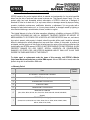
User’s Manual
Fingerprint Identification
Proximity / PIN Reader
Table of Contents
1. Important Safety Instructions ..............................................................................................5
2. General ..................................................................................................................................6
3. Features.................................................................................................................................6
4. Specification .........................................................................................................................7
5. Identifying Supplied Parts....................................................................................................9
6. Product Overview .................................................................................................................9
6.1. FUNCTIONS ....................................................................................................................9
6.2 PRODUCT EXPLANATION.............................................................................................10
6.2.1 PANEL DESCRIPTION ...........................................................................................10
6.2.2. COLOR CODED & WIRING TABLE ...................................................................... 11
7. Installation Tips & Check Point ......................................................................................... 11
7.1 CHECK POINTS BEFORE INSTALLATION....................................................................12
7.1.1 SELECTION OF CABLE.........................................................................................12
7.1.2 RECOMMENDED CABLE TYPE AND PERMISSIBLE LENGTH OF CABLE.........12
7.2 CHECK POINT DURING INSTALLATION.......................................................................13
7.2.1 TERMINATION RESISTOR ....................................................................................13
7.2.2 HOW TO CONNECT TERMINATION RESISTORS................................................14
7.2.3 GROUNDING SYSTEM FOR COMMUNICATION CABLE .....................................14
8. Installation of the Product..................................................................................................15
8.1 TEMPLATE......................................................................................................................15
8.2 SYSTEM INITIALIZATION (External Reader Port)..........................................................16
8.3 WIRING...........................................................................................................................16
8.3.1 POWER ..................................................................................................................16
8.3.2 OUTPUT CONNECTIONS......................................................................................17
9. Communication...................................................................................................................17
9.1 RS232 COMMUNICATION PORT CONNECTION..........................................................17
9.2 RS422 COMMUNICATION PORT CONNECTION..........................................................17
9.2.1 RS422 CONNECTION (SINGLE FINGER006 CONNECTION) ..............................17
9.2.2 RS422 CONNECTION (MULTIPLE FINGER007 CONNECTIONS)........................18
9.3 DIAL UP MODEM............................................................................................................19
9.4 TCP/IP CONVERTER (EXTERNAL VERSION) ..............................................................19
10. Basic Setting .....................................................................................................................20
10.1 INITIALIZATION OF FINGER006..................................................................................20
10.2 HOW TO ENTER THE SETUP MENU ..........................................................................21
10.3 ID REGISTRATION .......................................................................................................21
2
11. Operation ...........................................................................................................................24
11.1 NORMAL OPERATION .................................................................................................24
11.2 DATA OUTPUT FORMAT (SETUP MENU F2) ..............................................................24
11.2.1 WIEGAND OUTPUT FORMAT............................................................................24
11.2.2 ABA TRACK II MAGSTRIPE OUTPUT FORMAT ................................................25
11.3 DATA OUTPUT FORMAT (SETUP MENU F2) ..............................................................26
11.3.1 NORMAL MODE .................................................................................................26
11.3.2 EXTENSION MODE............................................................................................27
12. Setting Changes................................................................................................................28
12.1 SETUP MENU F1..........................................................................................................29
12.1.1 READER MODE SETTING.................................................................................30
12.1.2 TIME SETTING ...................................................................................................30
12.1.3 TYPE SELECTION .............................................................................................31
12.1.4 COMMUNICATION ID (ADDRESS) DISPLAY ....................................................32
12.1.5 BAUD RATE SETTING .......................................................................................33
12.1.6 MASTER ID CHANGE ........................................................................................33
12.1.7 SYSTEM INITIALIZE...........................................................................................34
12.1.8 CARD ID CLEAR ................................................................................................34
12.1.9 KEYPAD INPUT SETTING..................................................................................34
12.2 SETUP MENU F2..........................................................................................................35
12.2.1 LCD DISPLAY SETTING ....................................................................................35
12.2.2 OUTPUT MODE SETTING .................................................................................36
12.2.3 INPUT MODE SETTING .....................................................................................36
12.2.4 OUTPUT TYPE SETTING...................................................................................36
12.2.5 LED_BUZZER_CONTROL .................................................................................36
12.2.6 FUNCTION KEY OUT.........................................................................................36
12.3 SETUP MENU F3..........................................................................................................37
12.3.1 CARD REGISTRATION ......................................................................................38
12.3.2 ID DELETE .........................................................................................................40
12.3.3 ID LIST................................................................................................................40
12.3.4 REGISTERED ID COUNT ..................................................................................41
12.3.5 STORED FP COUNT..........................................................................................41
12.4 SETUP MENU F4..........................................................................................................42
12.4.1 VERSION CHECK ..............................................................................................43
12.4.2 MEMORY TEST..................................................................................................43
12.4.3 LCD TEST...........................................................................................................43
12.4.4 KEYPAD TEST....................................................................................................43
12.4.5 READER TEST...................................................................................................44
3
12.4.6 COMMUNICATION TEST ...................................................................................44
12.4.7 FINGERPRINT MODULE VERSION ..................................................................44
12.4.8 FINGERPRINT MODULE TEST .........................................................................44
13. FCC Registration Information..........................................................................................45
14. Warranty Policy and Limitation of Liability.....................................................................46
15. Template ............................................................................................................................47
4
1. Important Safety Instructions
When using Fingerprint Identification (Proximity / PIN) Reader, basic safety precautions should
always be followed to reduce the risk of fire, electrical shock, and injury to persons.
In addition, the following safety guides should also be followed:
1. Fully read and understand all instructions and follow them completely.
2. Follow all warnings and instructions marked on the product.
3. Do not use liquid or aerosol cleaners. Use a damp cloth for cleaning. If necessary, use mild soap.
4. Do not use this product near water.
5. Only operate this product using the type of power source indicated. If you are not sure of the type
of power supplied to your installation site, consult your dealer of local power company.
6. Never insert objects of any kind into the product or through the cabinet slots as they may touch
voltage points and/or short circuit parts possibly resulting in fire or electric shock.
Never spill liquid of any kind on the product.
7. Never disassemble this product by yourself; take the unit to a qualified service center
whenever service or repair is required. Opening or removing the covers may expose you to
dangerous voltages or other risks. Also, incorrect reassembly can cause electric shock when the
unit is subsequently used.
8. Unplug this product from the Direct Current (DC) power source and refer to qualified service
personnel under these conditions:
a. When the power supply cord or plug is damaged or frayed.
b. If liquid has been spilled on the product.
c.
If the product does not operate normally after following the operating instructions in this
manual.
Adjust only those controls that are covered by the operating instructions in this manual.
Improper adjustment of other controls that are not covered by this manual may damage
the unit and will often require extensive work by a qualified technician to restore normal
operation.
d. If the product exhibits a distinct change in performance.
5
2. General
The Star FINGER006/P / iPASS IP-FINGER006 / IDTECK FINGER006SR is such a highly advanced and intelligent fingerprint reader (with a keypad) with a powerful 32bit and dual 8bit
microprocessor to meet the market requirement for a robust integrated solution for access control
and time & attendance.
The unit has been designed to be flexible and reliable in providing the ultimate biometrics high
security at a reasonable cost.
This user-friendly device allows you to register up to 720 fingerprint IDs (optional 2,000/4,500) and
add / delete user IDs conveniently.
With the built-in 4" RF reader, the keypad for Personal Identification Numbers (PIN), and a sophisticated biometric fingerprint module, the FINGER006 offers up to three levels of ID verification.
Any combination of Proximity, PIN, and Biometric may be used and different verification levels can
be customer programmed for each user or user group.
3. Features
- 125KHz Proximity / PIN and Fingerprint Recognition
- 1,000 / 2,000 / 4,000 Fingerprint Users
- 1:1 Verification and 1: N Identification
- 2 Fingerprint Storage Templates
- Identification Method:
by PIN Key (default)
by Auto Touch Sensor (optional) : FINGER006A, FINGER006PA, FINGER006EXA
- ID Only Function for Persons with Unregisterable Fingerprints
- Network Communication via RS232 / RS422 / RS485 (Max.256ch),
TCP/IP (External LAN Converter Required)
- 1 ea of External Reader Port (FINGER006EX): 26bit Wiegand, 4 / 8bit Burst for PIN and ABA Track II
- 26bit Wiegand and ABA Track II Output Format
- High Protection from Scratch and ESD (Electro Static Discharge)
- High Quality Optical Sensor
- Dual Tamper Switches
- Options:
Auto Touch Sensor for Identification (FINGER006A, FINGER006PA, FINGER006EXA)
Supervisory Signal
- Compatible Software: STARWATCH DUAL PRO I / II, STARWATCH iTDC PRO I / II
- Compatible Controller: iCON100, iTDC, Third Party Controller, Standalone Controller
6
* Comparison Table
Built-in 125KHz (4”) Proximity Reader
FINGER006
RF(PIN) Only / Fingerprint Only / RF(PIN)+ Fingerprint
RF(PIN)+P/W(4digit) / RF(PIN)+P/W+ Fingerprint
PIN(4~8digit) Only / Fingerprint Only / PIN + Fingerprint
FINGER006P
PIN + P/W(4digit) / PIN+ P/W+ Fingerprint
Built-in 1ea of External Reader Port
FINGER006EX RF(PIN) Only / Fingerprint Only / RF(PIN)+ Fingerprint
RF(PIN)+P/W(4digit) / RF(PIN)+P/W+ Fingerprint
FINGER006A Auto Touch Sensor for Identification
FINGER006PA Auto Touch Sensor for Identification
FINGER006EXA Auto Touch Sensor for Identification
4. Specification
Model
FINGER006
CPU
FINGER006P
FINGER006EX
32bit ARM9 and Dual 8bit Microprocessor
Fingerprint
Module
Memory
Controller
Program
Memory
Data Memory
128KByte Flash Memory
128KByte / 256KByte / 512KByte Flash Memory
Program
Memory
64KByte Flash Memory
Data Memory
512KByte SRAM (Battery back up)
Fingerprint User
1,000 / 2,000 / 4,000 Fingerprint Users
Fingerprint Template Size
800 Bytes for 2 Fingerprint Templates
Passive Type
Read Range
Active Type
Reading Time (Card)
IDK50 / IMC125:
Up to 2 inch (5cm)
IDC80 / IDC170:
Up to 4 inch (10cm)
PIN Only
IDA150 / IDA200
Comapatible
30ms
Verification / Identification Time
Less than 1sec. / Less than 2sec.
Power / Current
External Reader Port
PIN Only
DC 12V / Max.300mA
N/A
Communication
N/A
1ea
(26bit Wiegand,
4/8bit Burst for PIN,
ABA Track II)
RS232 / RS422 / RS485 (Max.256ch)
7
TCP/IP (External LAN Converter required)
9,600bps (recommended) /
4,800bps, 19,200bps and 38,400bps (selectable)
2ea (Error-Input, OK-Input)
Baud Rate
Input Port
Output Port
2ea (Error-Output , OK-Output (Open Collector Output))
Output Format
26bit Wiegand, ABA Track II
Character LCD (2 Lines x 16 Char) /
65.6mm x 13.8mm (2.62” x 0.55”) Screen
LCD
Keypad
16 Key Numeric Keypad with Back Lighting
LED Indicator
3 Array LED Indicators (Red, Green and Yellow)
Beeper
Piezo Buzzer
Operating Temperature
Fingerprint
Module
-15° to +40°C (+5° to +104°F)
LCD
0° to +50°C (+32° to +122°F)
Controller
-15° to +70°C (+5° to +158°F)
RF Reader
-35° to + 65°C (-31° to +149°F)
Operating Humidity
10% to 90% relative humidity non-condensing
Color / Material
Dimension (W x H x T)
Dark Pearl Gray / Polycarbonate
161.5mm x 134mm x 48.5mm (6.36” x 5.28” x 1.9”)
Weight
547g (1.21lbs)
Certification
MIC
* Fingerprint Module Specification
Resolution
500dpi
Capture Image Size
356 X 292 pixels
Extraction Image Size
248 X 292 pixels
Sensing Area
12.7mm X 14.9mm
Scanner
High Quality Optical Sensor
FAR(False Acceptance Ratio)
0.001%
FRR(False Reject Ratio)
0.1%
ESD(Electro Static Discharge)
15KV
Verification Time
Less than 1sec.
Identification Time
Less than 2 sec.
8
5. Identifying Supplied Parts
Please unpack and check the contents of the box.
Main Unit
Wall Mount
O-ring
User’s Manual
(1ea)
(1ea)
(5ea)
(1copy)
6. Product Overview
6.1. FUNCTIONS
Operation with the Host Computer
ID data transactions can be managed via the host computer. The data transmitted from
the controller can be displayed and stored on the host PC.
Data Retention
All user information and event data are retained permanently, even in power failure.
※ For versions lower than V.4.0.0, the backup battery switch must be set correctly
before the unit runs. The controller retains all user information data for 30 days, even in
power failure. However, V4.0.0 or higher doesn’t have a backup battery because those
higher versions use a flash memory which is nonvolatile and therefore retains data in the
event of power failure.
Keypad
The built-in keypad and the LCD screen let you perform manual programming without a
PC connected.
Dual Finger Mode
Dual Finger Mode is a function that lets a user register two fingers for one ID so that the
user can receive authentication with either of the two registered fingers. This is useful
when a user’s finger is injured.
1:N Identification
A user can gain authentication using the fingerprint alone without RF card or PIN. You can
set this function through the <TYPE SELECTION> in SETUP MENU F1. In the
IDENTIFICATION MODE, the security level is automatically increased and it causes
FRR(False Rejection Ratio) to get higher, which may result in reduction of successful
recognition rate. When using this mode, the user has to press the <ENT> key first, and
then the fingerprint scanner waits for a fingerprint to be scanned. When the fingerprintscan is completed, FINGER006 identify the user and makes corresponding outputs.
9
z FINGER006 has a sensor (OPTION!). Normally, a user needs to press <ENT> in
the identification mode before placing their finger on the sensor. However, if a
sensor is installed, FINGER006 detects the user’s finger and scans it automatically.
z CAUTION: The number of registrants must be less than 50 on this mode.
Voice Message - Option
The FINGER006 can optionally have a voice chip and small power amp (300mW). If you
connect a speaker, you can hear the voice output while operating.
6.2 PRODUCT EXPLANATION
6.2.1 PANEL DESCRIPTION
LCD Display
Fingerprint
Scanner
3 LED Indicators
(showing system status)
16 Numeric keypad
Function keypad
FINGER006 (Versions lower than V4.0.0) has a S/W (reverse side – Template hole) for the
backup battery connection, which is left open circuit to prevent any current consumption of
backup battery (Figure: DIP Switch Setting). Before FINGER006 installation, the S/W needs to be
connected so that the backup battery can be activated to retain the memory during power failure.
FINGER006 V4.0.0 or higher doesn’t have a backup battery, so it doesn’t have a S/W, either.
Figure: DIP Switch Setting
Figure: DIP Switch location
10
6.2.2. COLOR CODED & WIRING TABLE
SIGNAL
COLOR
Main Power (+12V)
Red
Power Ground (GND)
Black
ABA Track II CP Out
Orange
Wiegand Data 0 Out /
ABA Track II Data Out
Green
Wiegand Data 1 Out /
ABA Track II Clock Out
White
Error Signal Out
Gray with Red stripe
OK Signal Out
White with Red stripe
Tamper Switch Out
Purple with White stripe
Speaker Out (+)
Brown with White stripe
Speaker Out (-)
Purple
ABA Track II CP In
Orange with White stripe
Wiegand Data 0 In (EX) /
ABA Track II Data In (EX)
Pink
Wiegand Data 1 In (EX) /
ABA Track II Clock In (EX)
Cyan
Error Signal In
Blue with White stripe
OK Signal In
Yellow with Red stripe
RS232 (TX)
Black with White stripe
RS232 (RX)
Red with White stripe
RS422 (TX+)
Gray
RS422 (TX-)
Yellow
RS422 (RX+)
Brown
RS422 (RX-)
Blue
* Please cut out the tail connector before installation.
7. Installation Tips & Check Point
Installing the Star FINGER006/P / iPASS IP-FINGER006 / IDTECK FINGER006SR is an easy task.
It can be installed with common hand tools and readily available communications wires.
This section provides information about wiring, wire runs and other information to make the
installation quick and easy.
11
7.1 CHECK POINTS BEFORE INSTALLATION
7.1.1 SELECTION OF CABLE
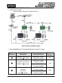
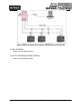
System installation cabling will be configured as follow.
Figure: System Installation Layout
7.1.2 RECOMMENDED CABLE TYPE AND PERMISSIBLE LENGTH OF CABLE
Reference
①
②
③
Description
Cable Specification
Maximum
Distance
Controller Power (DC12V)
Controller
Belden #9409, 18 AWG
2 conductor, unshielded
30m
Reader (Power and Data)
Belden #9512, 22 AWG
4 conductor, shielded
DC Power
FINGER006
Belden #9514, 22 AWG
8 conductor, shielded
Controller
Belden #9512, 22 AWG
4 conductor, shielded
Door Contact
Exit Button
Sensor Input
Input
Belden #9514, 22 AWG
8 conductor, shielded
Controller
12
150m
300m
Door Lock, Alarm Device
④
Lock (Alarm)
Controller
RS232 Cable
⑤
Converter
Host P.C.
Belden #9409, 18AWG
2 conductor, unshielded
300m
Belden #9829, 24 AWG
2-twisted pair, shielded
15m
RS485 Cable
⑥
Controller
Converter
Controller
Controller
Controller
FINGER006
FINGER006
FINGER006
FINGER006
Converter
RS422 Cable
Controller
Controller
Controller
FINGER006
FINGER006
* Thicker
Belden #9829, 24 AWG
2-twisted pair, shielded
1,200m
Converter
Controller
Belden #9830, 24 AWG
3-twisted pair, shielded
FINGER006
FINGER006
Converter
wires are necessary if the connected reader consumes a higher current.
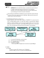
7.2 CHECK POINT DURING INSTALLATION
7.2.1 TERMINATION RESISTOR
Termination resistors are used to match impedance of the network to the impedance of the
transmission line being used. When impedance is mismatched, the transmitted signal is
not completely absorbed by the receiver and a portion of signal is reflected back into the
transmission line.
The decision whether or not to use termination resistors should be based on the cable
length and data rate used by the communication system.
For example, if you use 9,600 baud rate and 1,200m length of cable, the propagation
velocity of cable is 0.66 x speed of light (This value is specified by the cable manufacturer),
if we assume the reflections will damp out in three round trip up and down the cable length,
the transmitted signal will stabilize 18.6us after the leading edge of a bit. Since the data bit
is captured in the middle of the bit which is approximately 52us after the leading edge of a
bit. The reflection stabilizing time 18.6us is much before the center of the bit therefore the
termination resistors are not required.
However, if you install the cable to maximum length, the impedance of cable and network
is mismatched and the transmitted signal is overlapped by the reflected signal. In this case,
it is recommended to add termination resistors to the end of the receiver lines. A 120Ω
resistor can be used for termination resistor in parallel between the receiver lines “A” and
13
“B” for 2 wires RS485 system or “RX+” and “RX-” for 4 wires RS422 system. A termination
resistor of less than 90Ω should not be used and no more than 2 terminations should be
used in one networking system.
7.2.2 HOW TO CONNECT TERMINATION RESISTORS
Figure: Termination resistors for 2-wire RS485 communication system
Figure: Termination resistors for 4-wire RS422 communication system
7.2.3 GROUNDING SYSTEM FOR COMMUNICATION CABLE
We recommend to use proper grounding system on the communication cable. The best
method for grounding system is to put the shield wire of the communication cable to the 1st
class earth grounding; however it is not so easy to bring the earth ground to the
communication cable and also the installation cost is raised.
There will be three grounding point where you can find during installation;
1) Earth Ground
2) Chassis Ground
3) Power Ground
The most important point for grounding system is not to connect both ends of shield wires
to the grounding system; in this case there will be a current flow through the shield wire
when the voltage level of both ends of shield wire is not equal and this current flow will
create noise and interfere to communications.
For the good grounding, we recommend to connecting ONLY one end of shield wire of
communication cable to grounding system; If you find earth ground nearby, then connect
one end of shield wire to earth ground; If you do not have earth ground nearby, then find
chassis ground and connect one end of shield wire to chassis ground; If you do not find
both earth ground and chassis ground, then connect one end of shield wire to power
ground. (GND of FINGER007)
Note that if the chassis ground is not properly connected to the earth and floated from the
ground level, then grounding to the chassis ground will give the worst communication; in
this case we recommend to using power ground instead of chassis ground.
14
Figure: Grounding system
8. Installation of the Product
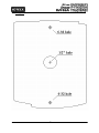
8.1 TEMPLATE
• Tear off the Template page at the back of this manual and use the Template to drill two 6-32
holes and one ½” hole on the proper location of the wall to mount the Wall Mount bracket as
shown below.
(If the gang box is already installed on the wall, then skip this step.)
15
• Using 2 screws, install wall mount to the wall.
※Caution: Before mounting the Star FINGER006/P/EX / iPASS IP-FINGER006 / IDTECK
FINGER006SR unit to the Wall Mount bracket, an operational test of the unit should
be completed, because the locking pins will lock the unit to the Wall Mount.
Removing the unit from the Wall Mount bracket after it has been snapped in place
may cause damage to the bracket and prevent reattachment.
• Insert 5 O-Rings to the Wall Mount as indicated, then run the cable from the main unit through
the center hole and snap in place the main unit to Wall Mount. Make sure that the main unit is
securely locked in place with Wall Mount.
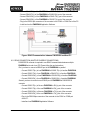
8.2 SYSTEM INITIALIZATION (External Reader Port)
Hardware initialization must be done before installation of FINGER006. For versions lower than
V4.0.0, the Backup Battery Switch on the back side should be connected before hardware
initialization. Hardware initialization can be done using the external reader port. First, turn off the
system power and connect 3 wires (pink, cyan and black (GND)) together, and turn on the system
power. Then, the “Initialize beep” will sound and the LCD message ① will be displayed.
System Initialize
Master Password
System
1 – Yes, 0 - No
[____]
Initializing...
1
○
2
○
3
○
FP Module
System is Clear
Initializing...
Remove Wires!!
4
○
1.
2.
3.
4.
⑤
① : If you want H/W Initialization, press the <1> key.
② : Enter the initial master password(<3141>).
③, ④ : Initialization status.
⑤ : Initialization is completed
–Turn the power OFF and separate the 3 wire and turn the power ON again.
8.3 WIRING
8.3.1 POWER
- Connect the (+) wire of DC 12V power to the +12V (Red) wire.
- Connect the GND (-) wire of DC 12V power to the GND (Black) wire.
16
8.3.2 OUTPUT CONNECTIONS
Wiegand Data Connection
- Connect Data 0 of the controller to Wiegand Data 0 Out (Green wire).
- Connect Data 1 of the controller to Wiegand Data 1 Out (White wire).
- If you disconnect the power from the controller, connect the GND port between controllers.
ABA Track II Connection
- Connect Data 0 of the controller to ABA Track II Data Out (Green wire).
- Connect Data 1 of the controller to ABA Track II Clock Out (White wire).
- Connect CP of the controller to ABA Track II CP Out (Orange wire).
- If you disconnect power from the controller, connect the GND port between controllers.
Control Signal Connection
- Connect Error input of the controller to Error Signal Out (Gray with Red stripe wire).
- Connect Ok input of the controller to OK Signal Out (White with Red stripe wire).
- Connect Error output of the controller to Error Signal In (Blue with White stripe wire).
- Connect Ok output of the controller to OK Signal In (Yellow with Red stripe wire).
- Connect Tamper input of the controller to Tamper Switch Out (Purple with White stripe)
wire.
Speaker Signal Connection
- Connect the external speaker (+) to the Speaker Out (+) (Brown with White stripe wire).
- Connect the external speaker (-) to the Speaker Out (-) (Purple wire).
External Reader Connection (FINGER006EX)
[Wiegand Input]
- Connect Data 0 of the external reader to Wiegand Data 0 In (EX) (Pink wire).
- Connect Data1 of the external reader to Wiegand Data 1 In (EX) (Cyan wire).
[ABA Track II Input]
- Connect Data of the external reader to ABA Track II Data In (EX) (Pink wire).
- Connect Clock of the external reader to ABA Track II Clock In (EX) (Cyan wire).
- Connect CP of the external reader to ABA Track II CP In (Orange with White stripe wire).
9. Communication
9.1 RS232 COMMUNICATION PORT CONNECTION
A 9-pin connector (Serial communication connector, female) is required to connect
the FINGER006 to a host computer via RS232 communication. Please follow the instructions.
- Connect RS232-TX port of FINGER006 to the pin 2 of the 9-pin connector.
- Connect RS232-RX port of FINGER006 to the pin 3 of the 9-pin connector.
- Connect RS232-GND of FINGER006 to the pin 5 of the 9-pin connector.
Plug in the 9-pin connector to COM1 or COM2 Port of the host PC.
Install and run FINGER006 Application Software.
9.2 RS422 COMMUNICATION PORT CONNECTION
9.2.1 RS422 CONNECTION (SINGLE FINGER006 CONNECTION)
RS422/RS232 converter (CNP200) is required to use RS422 communication between
the FINGER006 and a host computer. Please follow the instructions.
17
- Connect RS422-TX(+) of the FINGER006 to RS422-RX(+) port of the converter.
- Connect RS422-TX(-) of the FINGER006 to RS422-RX(-) port of the converter.
- Connect RS422-RX(+) of the FINGER006 to RS422-TX(+) port of the converter.
- Connect RS422-RX(-) of the FINGER006 to RS422-TX(-) port of the converter.
- Plug in the RS232 9pin connector of the converter to the COM1 or COM2 Port of the PC.
- Install and run the FINGER006 Application Software.
Figure: RS422 Communication between FINGER006 and Host PC
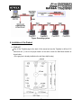
9.2.2 RS422 CONNECTION (MULTIPLE FINGER007 CONNECTIONS)
RS422/RS232 converter is required to use RS422 communication between multiple
FINGER006 units and a host PC. Please follow the next instructions.
First, you have to connect all RS422 port of all FINGER006s in parallel.
- Connect RS422-TX(+) of one FINGER006 to RS422-TX(+) of another FINGER006.
- Connect RS422-TX(-) of one FINGER006 to RS422-TX(-) of another FINGER006.
- Connect RS422-RX(+) of one FINGER006 to RS422-RX(+) of another FINGER006.
- Connect RS422-RX(-) of one FINGER006 to RS422-RX(-) of another FINGER006.
Second, you have to connect one of RS422 port of FINGER006 to RS422/RS232
converter.
- Connect RS422-TX(+) of the one FINGER006 to RX(+) port of the converter.
- Connect RS422-TX(-) of the one FINGER006 to RX(-) port of the converter.
- Connect RS422-RX(+) of the one FINGER006 to TX(+) port of the converter.
- Connect RS422-RX(-) of the one FINGER006 to TX(-) port of the converter.
- Plug in the RS232 9pin connector of the converter to the COM1 or COM2 port
of the PC.
- Install and run FINGER006 Application Software.
18
Figure: RS422 Communication between FINGER006s and the Host PC
9.3 DIAL UP MODEM
Please, see the Software manual.
9.4 TCP/IP CONVERTER (EXTERNAL VERSION)
Please, see the Software manual.
19
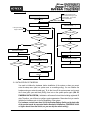
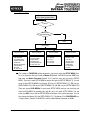
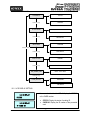
10. Basic Setting
If you turn on the system power
after connected 3 wires (pink, cyan
and black(GND)), you can enter
system initialize mode.
POWER ON
GENERAL BOOT
H/W RESET MODE
INITIAL BEEP( - - - -)
INITIALIZE BEEP( - - -)
In the system ready, LCD
display model name,
NO
SYSTEM READY
SYS. INITIALIZE ?
YES
ID INPUT ?
WAIT INITIIAL MASTER P/W
("3141")
YES
YES
MASTER ID ?
NO
RIGHT ?
NO
NO
YES
ENTER SETUP MENU
SYSTEM INITIALIZE
REGISTERED ID ?
NO
SETTINGIN SETUP MODE
YES
RF_PIN_ENABLE SETTING
CHECK FINGERPRINT or P/W
END SETTING ?
NO
NO
RIGHT ?
WAITING REBOOT
YES
OUTPUT CONTROL OF EACH
STATUS
YES
10.1 INITIALIZATION OF FINGER006
You need to initialize the hardware, before installation of the system or when you cannot
enter the setup menu (due to a system error or something wrong). You can initialize the
hardware using an external reader port. To do that, turn off the system power and connect
the 3 wires (pink, cyan and black (GND)), then turn on the system power again. (Ref. 5.3
FINGER006 INITIALIZATION). Initialization will erase all stored data including registered ID
data. Therefore, you will have to configure system parameters. Remember that you need to
initialize the Hardware prior to the first installation of the system.
For hardware version lower than V4.0.0, the Backup Battery Switch on the back side
of the product needs be connected before Hardware initialization. (FINGER006 V4.0.0
or higher doesn’t have the Switch, so you can skip the switch setting.)
20
System Initialize
Master Password
FP Module
1 – Yes, 0 - No
[3141]
Initializing..
System is Clear
Remove Wires!!
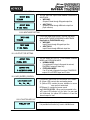
10.2 HOW TO ENTER THE SETUP MENU
For a setup or FINGER006 setting adjustment, you have to enter the SETUP MENU, first.
To do so, press the <0> key 8 times for Master ID (Default “00000000”) and the <ENT> key
and press the Master Password (Default “3141”) and the user can get into the SETUP
MENU. There are 4 main SETUP MENUs and you first get into [SETUP MENU F1]. You can
move to other SETUP MENUs by pressing <F1> key for [SETUP MENU F1], <F2> key for
[SETUP MENU F2], <F3> key for [SETUP MENU F3], and <F4> key for [SETUP MENU F4].
There are several SUB MENUs for each main SETUP MENU and you can scroll up and
down the SUB MENU by pressing <4> and <6> key in the main SETUP MENU. You can
press the <ESC> key to exit the SETUP MENU and return to the normal operation. You can
also change the Master ID in the [SETUP MENU F1]. The Master ID for FINGER006SR is a
10-digit number (Default “0000000000”) and the default Master Password is <3141>.
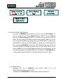
10.3 ID REGISTRATION
Registering User IDs to FINGER006. Select [SETUP MENU F3]
REGISTRATION] ,then follow the steps below.
The Master ID for FINGER006SR is a 10-digit number (Default “0000000000”).
21
Æ
[ID
1. Approach to the Registration Mode
MASTER CARD (PW) /
PW / FINGERPRINT
FINGER_006 [F1]
02/18 11:59:01
ID Registration Menu
SETUP MENU F3
Initial Master (<00000000>)/
Initial Password (<3141>)
ID REGISTRATION
ID REGISTRATION
1 - Card, 2 - Key
ENT
2. Registration by an RF Card (FINGER006 only)
Put ID CARD
Scanning…
<1>
Key
Approach Card to
Reader#1
PW/FP Input
Not using fingerprint (FP:0)
Fingerprint Use
(FP:1)
To Register FP
Put Your FP On..
Success
First Fingerprint Input
Fail
Success
ID Registered
[Q#1:_] [Q#2:_]
25500100
PW1234 FPX
Lift and Put FP
Waiting…
Second Fingerprint Input
After displaying fail reason,
initial display for ID registration
Registration Finish
Quality Display of
Registered Fingerprint
22
Fail
3. Registration by Keypad (FINGER006 & FINGER006P)
Card No.
Key InPut ID
Æ █________
<2>
Key
00000100
PW1234 FPX
to register
PW/FP Input
Not using fingerprint (FP:0)
Fingerprint Use
(FP:1)
To Register FP
Put Your FP On..
Success
First Fingerprint Input
Fail
ID Registered
[Q#1:_] [Q#2:_]
Success
Lift and Put FP
Waiting…
Second Fingerprint Input
After displaying fail reason,
initial display for ID registration
Fail
Registration Finish
4. After ID Registration is completed, return to the initial display by pressing the <ESC> Key.
5. You may register more than 1 ID. Register more IDs one by one, after the first ID registration is
done.
6. If you’re re-registering an ID and it is registered with a fingerprint already, you will be required
to enter the previously-registered fingerprint, first.
7. In the case of FINGER006P, you cannot register IDs using the RF card.
•
The [ID] is a kind of Personal Identification Number that can be entered using an RF Card or
the Keypad. An ID number recorded on an RF card consists of 3-digit Facility code from 000
to 255 and 5-digit ID number form 00000 to 65535 so that the 8-digit ID number cannot
exceed 25565535. (ID number of FINGER006SR has 10-digit decimal numbers (0000000001
~ 4294967295) ID number can not exceed 4294967295.)
•
The [PW] field is for password input. A password is necessary to access the doors if the
controller is being operated in RF+FINGERPRINT (P/W) or RF+P/W+FINGERPRINT Mode.
But, regardless of the operating mode, it is necessary to input a password during registration.
•
The [FP] field is for selecting whether or not to register a fingerprint for the user. If “1” is
entered for the value, the user has to register fingerprint. Then, the user can later attempt
access by a fingerprint in RF+FINGERPRINT (P/W) and RF +P/W+FINGERPRINT Mode. If
“0” is entered for the value, a fingerprint is replaced by a password.
23
11. Operation
11.1 NORMAL OPERATION
Power ON
When the Power is applied to FINGER006, the RED LED is turned on.
Registered Card Reading
When a registered card (or PIN) is read, the GREEN LED will be lit for 3 seconds (Default),
and ID data is sent through Wiegand or ABA Track II output line. If the “EXTENSION
MODE”(OUTPUT TYPE) is applied, an OK Signal is generated with ID data output. If the
“STAND ALONE”(TYPE SELECTION) setting is set to “NOT USE”, FINGER006
generates ID data and waits for a return signal (either OK or ERROR) from the controller.
Alarms (Unregistered / Password / Fingerprint Error)
When an unregistered card is read, the wrong password is entered or the wrong fingerprint
is scanned, the access is denied and the YELLOW LED is lit for 3 seconds (Defaults).
If the “EXTENSION MODE”(OUTPUT TYPE) is applied, an ERROR Signal is generated
(Low active, open collector) with ID data output.
11.2 DATA OUTPUT FORMAT (SETUP MENU F2)
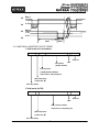
11.2.1 WIEGAND OUTPUT FORMAT
1. Data format ( * : FINGER006SR)
Bit 1
Bit 2∼9
Bit 10∼25
* Bit 2 ~ 33
: Even parity of bit 2 ~ bit 13
: Facility code (000 ~ 255)
: ID number (00000 ~ 65,535)
: ID number (0000000001 to 4294967295)
Bit 26
* Bit 34
: Odd parity
: Odd parity
24
2. Timing diagram
5V
Data 1
3.5V
0V
0.5V
40uS
5V
40uS
Data 0
3.5V
0.5V
0V
2mS
40uS
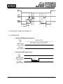
11.2.2 ABA TRACK II MAGSTRIPE OUTPUT FORMAT
1. Data format (for Card numbers)
Zero bit
ID number
LRC
(00000~65535)
Facility Code
(1248P (00000~00255))
low bit first, odd parity last
Start Character
(11010 Hex ‘B’)
Zero bit (10bit)
2. Data format (for PIN)
Zero bit
LRC
PIN (1char to 8char)
low bit first, odd parity last
Start Character
(11010 Hex ‘B’)
Zero bit (10bit)
25
3. Timing diagram
CP
CLK
(RD1)
1240us
940us
Data
(RD0)
6000us
6000us
1544us
11.3 DATA OUTPUT FORMAT (SETUP MENU F2)
11.3.1 NORMAL MODE
a. Registered ID/Registered Fingerprint
DATA OUTPUT
DATA
LINE
ERROR Signal
(Open collector)
OK Signal
(Open collector)
b. Unregistered ID/Fingerprint error
DATA
LINE
ERROR Signal
(Open collector)
500mS
OK Signal
(Open collector)
26
11.3.2 EXTENSION MODE
a. Registered ID/Registered Fingerprint
DATA OUTPUT
DATA LINE
ERROR Signal
(Open collector)
OK Signal
(Open collector)
b. Unregistered ID/Fingerprint error
DATA OUTPUT
DATA LINE
ERROR Signal
(Open collector)
OK Signal
(Open collector)
27
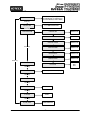
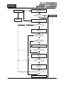
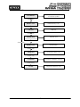
12. Setting Changes
INITIAL DISPLAY
(MODEL NAME, CURRENT TIME)
NO
ID INPUT?
YES
MASTER ID
/PW/FINGERPRINT ?
YES
NO
OPERATE GENERAL
MODE
SETUP MODE
SETUP F1 MODE
1. MODE SELECTION
2. TIME SETTING
3. TYPE SELECTION
4. COMM ID SETTING
5. BAUD RATE
6. MASTER ID CHANGE
7. SYS INITIALIZE
8. ID CLEAR
9. RF_PIN_INPUT
SETUP F2 MODE
SETUP F3 MODE
1. LCD DISPLAY
2. OUTPUT MODE
3. INPUT MODE
4. OUTPUT TYPE
5. LED/BUZZER_CON
6. FUNC_KEY OUT
1. ID REGISTRATION
2. ID DELETE
3. ID LIST
4. ID COUNT
5. FP COUNT
SETUP F4 MODE
1. F/W VERSION
2. MEMORY TEST
3. LCD TEST
4. KEYPAD TEST
5. READER TEST
6. COMM TEST
7. FP VERSTION
8. FP TEST
☞. For a setup or FINGER006 setting adjustment, you have to enter the SETUP MENU, first.
To do so, press the <0> key 8 times for Master ID (Default “00000000”) and the <ENT> key
and press the Master Password (Default “3141”) and the user can get into the SETUP
MENU. There are 4 main SETUP MENUs and you first get into [SETUP MENU F1]. You can
move to other SETUP MENUs by pressing <F1> key for [SETUP MENU F1], <F2> key for
[SETUP MENU F2], <F3> key for [SETUP MENU F3], and <F4> key for [SETUP MENU F4].
There are several SUB MENUs for each main SETUP MENU and you can scroll up and
down the SUB MENU by pressing <4> and <6> key in the main SETUP MENU. You can
press the <ESC> key to exit the SETUP MENU and return to the normal operation. You can
also change the Master ID in the [SETUP MENU F1]. The Master ID for FINGER006SR is a
10-digit number. (Default “0000000000”) and the default Master Password is <3141>.
28
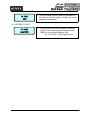
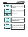
122.1 SETUP MENU F1
MODE SELECTION
RF Only (ID Only)
RF+FINGER(P/W) (ID+FINGER(P/W))
RF+P/W+FINGER (ID+P/W+FINGER)
Seach Key
TIME SETTING
YYYYMMDDhhmmssW
Seach Key
TYPE SELECTION
Seach Key
STAND ALONE
USE/NOT USE
FINGER006P
USE/NOT USE
USE DUAL FINGER
USE/NOT USE
ADAPTIVE MODE
USE/NOT USE
HIGH SECURITY
USE/NOT USE
IDENTIFICATION
USE/NOT USE
FP STATUS
NORMAL/
DRY/
WET
Seach Key
COMM ID SETTING
Seach Key
BAUD RATE
4800/9600(RECOMMENDED)/19200
Seach Key
MASTER ID CHANGE
Seach Key
SYSTEM INITIALIZE
YES/NO
Seach Key
ID CLEAR
YES/NO
Seach Key
RF_PIN_INPUT
ENABLE/DISABLE
29
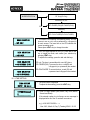
12.1.1 READER MODE SETTING
M ODE SELECTION
RF Only (ID Only)
SeachKey<4>,<6>
RF+FINGER(P/W) (ID+FINGER(P/W))
'ENT'
Seach Key
RF+P/W+FINGER(ID+P/W+FINGER)
MODE SELECTION
-->RF ONLY
MODE
MODE SELECTION
SELECTION
--> RF ONLY
-->RF
ONLY
MODE SELECTION
-->RF+FINGER (P/W)
MODE SELECTION
-->RF+P/W+FINGER
☞ This Menu is for selecting the operating mode. You can
choose to use or not to use a password (or a fingerprint)
for each access. The lower line on the LCD indicates the
current operating mode.
Please press <ENT> key to change the mode.
☞. Then, this figure appears on the LCD, press <4> or <6>
key to toggle the mode, and confirm your selection by
pressing <ENT> key.
To adjust other settings, press the <4> and <6> keys.
RF only: The door is accessible with a card (ID) alone.
RF+FINGER(P/W): To access the door, a card(ID) and
a fingerprint (or a password) are needed.
RF+PIN+FINGER: To access the door, a card (ID) and
a password and a fingerprint are needed.
12.1.2 TIME SETTING
TIME SETTING
MM/DD hh:mm:ss
YYYYMMDDhhmmssW
█______________
☞. The current time is displayed
To adjust the time setting, press the <ENT> key.
☞. Enter a 15-digit number (Year, Month, Day, Hour, Minute,
Second and Week).
If the entered number is out of range, an error message is
displayed after all of the 15 numbers are entered.
e.g.) <200106071330253> →
Year: 2001, Month: 6, Day: 7 (Tuesday) PM 01: 30: 25
30
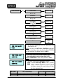
12.1.3 TYPE SELECTION
TYPE SELECTION
'ENT'
STAND ALONE
USE/NOT USE
‘ENT’ or ‘ESC’
USE/NOT USE
FINGER006P
‘ENT’ or ‘ESC’
USE/NOT USE
DUAL FINGER
‘ENT’ or ‘ESC’
ADAPTIVE MODE
USE/NOT USE
‘ENT’ or ‘ESC’
HIGH SECURITY
USE/NOT USE
‘ENT’ or ‘ESC’
IDENTIFICATION MODE
USE/NOT USE
‘ENT’ or ‘ESC’
NORMAL/
DRY/
WET
FP STATUS
USE STAND ALONE?
-->USE
☞. You can select whether you use the FINGER006 as a
Stand Alone or not.
NOTE: If this is set to <NOT USE>, FINGER006 generates
ID data and waits for a return signal (either OK or ERROR)
from the controller. (The default setting is <USE>.)
USE FINGER_006P?
-->NOT USE
☞. This menu comes after <STAND ALONE> setting.
(Only applicable to versions lower than V4.00)
NOTE: If FINGER006P is used, setting should be <USE>.
USE DUAL FINGER?
-->NOT USE
☞. This menu comes after <FINGER006P> setting.
NOTE: If you set Dual Finger Mode to ‘USE ’, you can
register 2 different fingers for your ID so that if
one finger is injured, you may verify your ID with
the other registered finger.
USE
DUAL FINGER?
NOT USE
USE
No. of Template/Finger
2 fingerprint storage templates for a single finger.
1 fingerprint storage template each for 2 different fingers.
31
Authentication
Success Ratio
High
Low
Recommended
Authentication Mode
Identification Mode
Verification Mode
USE ADAPTIVE MODE?
-->USE
☞. This menu comes after <DUAL FINGER>.
NOTE: In ADAPTIVE MODE, scanning quality is better than
normal mode. But, scanning speed is longer than normal
mode.
HIGH SECURITY?
-->NOT USE
☞. This menu comes after <ADAPTIVE MODE>.
NOTE: If HIGH SECURITY is set to USE, FINGER006
automatically removes after-images during the fingerprint
capturing process. In this mode, identification/verification
errors caused by after-images can be reduced but the
processing time can be a little bit longer.
CAUTION: While this feature is applied, light fingerprint
images from dry fingers cannot be distinguished from afterimages. Therefore, identification/ verification errors will
increase for dry fingers.
IDENTIFICATION?
-->NOT USE
☞. This menu comes after <ADAPTIVE MODE>.
NOTE: In IDENTIFICATION MODE, 1:N authentication can
be used. You can verify an ID via a fingerprint alone. In this
mode, you must press <ENT> before fingerprint
authentication unless a sensor is installed.
(For FINGER006 a (finger detect) sensor is optional.)
* If not using Identification Mode, you’re using Verification Mode.
FP STATUS
-->NORMAL
☞. This menu comes after <IDENTIFICATION> setting.
NOTE: <NORMAL> Default Use
<DRY> Used in too dry areas
<WET> Used in too humid areas
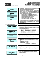
12.1.4 COMMUNICATION ID (ADDRESS) DISPLAY
COMM ID SETTING
☞. You can set the communication ID for the FINGER006.
To change the communication ID, press <ENT> key.
COMM ADDRESS
000
☞. The number on the LCD is the current communication ID
(Device No.) Please, press <ENT> key again to set a new
communication ID.
COMM ADDRESS
001
☞. Enter the new ID (3-digit number) where the cursor is
blinking.
A Communication ID must be in the range of 000 to 255.
32
12.1.5 BAUD RATE SETTING
BAUD RATE
9600
BAUD RATE
--> 9600
BAUD RATE
--> 19200
☞. FINGER006 supports 4800/9600/19200 of baud rate
and the recommended setting is 9600bps.
A wrong baud rate setting will cause communication
errors, and the baud rate settings of FINGER006 and
host PC should be same. If any communication problem
occurs, please check the following;
- Check COMM ID of FINGER006 and host PC
- Check BAUD RATE of FINGER006 and host PC
- Check communication port and cable
- Check COM port setup of host PC;
Parity - None, Data Bit - 8 bit, Stop Bit - 1 bit
To change the baud rate, press <ENT> key and select
desired baud rate by pressing <4> or <6> key then
press <ENT> key.
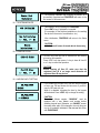
12.1.6 MASTER ID CHANGE
MASTER ID CHANGE
CARD & Key Use
1-Card, 2-Key
Scanning …
☞. Press <ENT> key to change the current Master ID. You
should use the new Master ID to access the SETUP MENU
after changing the Master ID.
Model
Default Master ID / PASSWORD
FINGER006
: “00000000” / ”3141”
FINGER006SR : “0000000000” / ”3141”
☞. FINGER006 is waiting for an RF card to be registered.
The card number will appear with a beep as the card is
read.
INPUT NEW MASTER
[█_______]
☞. FINGER006 is waiting for a keypad that is to be registered.
FINGER006: 4 to 8 digits
FINGER006SR: 10 digits
(“0000000001” ~ “4294967295”)
Put Master FP
☞. A fingerprint for the new Master ID is necessary to be
scanned.
If there has been a Master ID already, the fingerprint
of the ID should be scanned first.
Enter Password
█___
☞. Enter a new Master password (four digits) and finish
changing Master ID
33
Master Card
Registered
☞ The message indicates that changing the Master ID is
successfully completed and FINGER006 will return to the
first screen of this menu soon.
12.1.7 SYSTEM INITIALIZE
SYS INITIALIZE
Sys Initializing
1 – Yes, 0 - No
☞ This operation is for initializing the FINGER006.
Press <ENT> key, if initialization is needed.
(For example, for the first-time installation or for resetting
the device in the event of a malfunction, etc.)
After initialization, FINGER006 will return to the Setup
menu.
`
System
Initializing …
CAUTION:
Initialization will erase all stored data in the memory.
12.1.8 CARD ID CLEAR
CARD ID CLEAR
Card ID Clear
1 – Yes, 0 - No
☞. All User IDs (Card IDs) can be cleared from the memory
at once by this operation.
Press <ENT> key then press <1> key to clear all User ID
or <0> key to cancel the operation.
CAUTION:
Before clearing all User ID, make sure that the
registered User ID is no longer used otherwise all
registered User ID may be lost.
12.1.9 KEYPAD INPUT SETTING
RF_PIN_INPUT
ENABLE
RF_PIN_INPUT
--> DISABLE
☞. If you enable the PIN input, then you can use the keypad
to enter your PIN and access the door even if you don’t
carry the RF card with you.
When it is disabled, accessing the door by the keypad
will be denied. Press <ENT> key to change the setting.
CAUTION:
The default Master number, “00000000”, must be
replaced with a new Master card number before
disabling keypad input Otherwise, you CANNOT access
the setup menu again. If this happens, the only thing you
can do is hardware initialization. Do not use this menu
with FINGER006P.
34
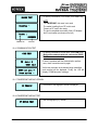
12.2 SETUP MENU F2
LCD DISPLAY
STATUS
Search Key
CARD NO.
OUTPUT MODE
WIEGAND
Search Key
ABA TRACK II
INPUT MODE
WIEGAND
Search Key
ABA TRACK II
OUTPUT TYPE
NORMAL
Search Key
Search Key
EXTENSION
GLXX YLXX BZXX
LED_BUZZER_CON
Search Key
FUNC_KEY OUT
4BIT BURST
8BIT BURST
12.2.1 LCD DISPLAY SETTING
LCD DISPLAY
STATUS
LCD DISPLAY
Æ CARD NO
☞. You can select whether the LCD will display the STATUS
or the CARD number.
•
•
STATUS: Display the status of reading ID.
CARD NO: Display the ID number of the presented
card.
35
12.2.2 OUTPUT MODE SETTING
OUTPUT MODE
WIEGAND
OUTPUT MODE
Æ ABA TRACK
☞. You can select the output format between WIEGAND or
ABA TRACK.
• WIEGAND:
Outputs ID data through Wiegand output line.
• ABA TRACK:
Outputs ID data through ABA track output line.
(Open collector)
12.2.3 INPUT MODE SETTING
INPUT MODE
WIEGAND
INPUT MODE
Æ ABA TRACK
☞. This is input mode setting menu. The user can select
whether INPUT MODE is WIEGAND or ABA TRACK.
(Applicable to FINGER006EX only.)
• WIEGAND:
Input ID data through Wiegand input line.
• ABA TRACK:
Input ID data through ABA track input line.
12.2.4 OUTPUT TYPE SETTING
OUTPUT TYPE
NORMAL MODE
OUTPUT TYPE
Æ EXTENSION MODE
☞. You can select the OUTPUT TYPE between NORMAL
MODE and EXTENSION MODE.
• NORMAL MODE:
If a registered ID or/and a fingerprint is entered,
FINGER006 outputs ID data only.
• EXTENSION MODE:
If an ID or/and a fingerprint is entered, FINGER006
outputs OK or ERROR signal and ID data.
12.2.5 LED_BUZZER_CONTROL
LED_BUZZER_CON
GL__ YL__ BZ__
☞. This function controls the LED and Buzzer of the reader.
GL (Green LED): controls the card reading status.
YL (Yellow LED): controls the error indication in case a
user card isn’t authorized.
BZ (Buzzer): It controls the buzzer sound.
e.g.) GL03 YL03 BZ01 : When card is presented to the
unit, green LED indicator is lit for 3sec. If a user card
isn’t authorized, the yellow LED indicator is lit and the
buzzer beeps for 1sec.
12.2.6 FUNCTION KEY OUT
FUNC_KEY OUT
☞. This is set to use function key of the reader.
It is possible that function key is set to 4bit/8bit burst.
36
12.3 SETUP MENU F3
ID REGISTRATION
Registration Method Select
CARD/KEY
Enter ID (4 ~ 8 Digit)
KEY
ID DELETE
Enter CARD or ID
CARD/KEY
Search Key
Enter ID
(FINGER006P)
KEY
ID LIST
Display registered ID and flag
Search Key
Search Key
Search Key
ID COUNT
Display Stored ID Count
Search Key
ID COUNT
Display Stored ID Count
Search Key
FP COUNT!
Display Stored ID Count
37
12.3.1 CARD REGISTRATION
ON
ID REGISTRATION
SELECT REGISTRATION METHOD
(FINGER006)
FINGER006
CARD or KEY ?
DISPLAY
ERROR
KEY
FINGER006P
ENTER NEW ID
(4 ~ 8 Digits)
YES
MASTER ID ?
NO
INPUT
P/W and FINGERPRINT flag
USE FINGERPRINT ?
YES
ALREADY EXIST ID ?
NO
YES
CERTIFICATION ID's FINGERPRINT
NO
SUCCESS ?
YES
REGISTRATION NEW ID's
FINGERPRINT
(First time)
NO
NO
SUCCESS ?
YES
REGISTRATION NEW ID's
FINGERPRINT
(Second time)
NO
SUCCESS ?
YES
COMPLETION ID REGISTRATION
38
CARD
PRESENT CARD
ID REGISTRATION
CARD & Key Use
1 – CARD, 2 - Key
Put ID CARD
Scanning …
☞. An ID number can be registered to the FINGER006 by
RF cards or through the keypad.
For registration by RF cards, press <1> key
For registration using the keypad, press <2> key,
Or, you can quit the registration by pressing <ESC>.
☞. In the case of registration by RF card, FINGER006 will
be waiting for an RF card to be registered.
In the case of registration by keypad, you can register
8-digit ID. (As for FINGER006SR, an ID is 10 digits)
Key Input ID
--> █_______
XXXXXXXX
PW____ FP_
XXXXXXXX
ID Registered
To Register FP
Put Your FP On ..
Lift and Put FP
Waiting ...
ID Registered
[Q#1: ] [Q#2: ]
☞.This screen shows the ID number you just entered on the
upper line, and you are required to enter the following
information for the ID:
4-digit password and FP flag (Enter <1> to register a
fingerprint, <0> not to.). If you enter <0> for the FP flag,
the message ‘ID Registered’ will be shown for a moment
and the controller will wait for another PIN number to be
entered. You can register other PINs in the same way.
Please, press <ESC> key to quit the registration.
(The user can change the PW and the FP flag in the
same way as the new registration.)
☞.If you enter <1> for the FP flag to register a fingerprint for the ID, this screen will appear on the LCD and
the red light will be illuminated from the fingerprint input
sensor. As the fingerprint should be scanned twice, put
the finger to the sensor, once the message is displayed,
lift the finger off briefly and put it again.
NOTE:1. The fingerprint registration requires 2 slightly
different images of a fingerprint. For that reason, after the
first scan, the finger must be lifted briefly.
2. When an ID number that is registered with a
fingerprint is re-registered to change options, the
current fingerprint is required to be scanned.
☞. The quality level of the registered fingerprint image.
* [Q#1: ] – Quality of the first fingerprint
[Q#2: ] – Quality of the second fingerprint
39
1) PW (password): The password used in RF + FINGER (P/W) and RF + P/W + FINGER mode.
2) FP (Fingerprint flag)
1: To register a fingerprint for the ID that is being registered.
(If you’re re-registering an ID to change options and the ID is registered with a fingerprint,
the previously-registered fingerprint should be scanned before you can change options.)
0: When you don’t need to register a fingerprint for the ID.
If the controller is set to operate in RF+FINGER (P/W) or RF+P/W+FINGER mode, it will
operate in RF+P/W (Password) mode for the ID.
12.3.2 ID DELETE
ID DELETE
Enter Card No.
-> █________
☞. This is registered the ID Deletion menu.
To delete some registered ID(s), press <ENT> key.
Enter the ID number or present the card that you’d like
to be deleted.
ID Deleted
12.3.3 ID LIST
ID LIST
☞. If you would like to check the list of the registered user
IDs, press the <ENT> key in this menu.
“MEMORY EMPTY” message will be displayed when
there is no registered user ID.
MEMORY
EMPTY
XXXXXXXX
XXXX XX XX X
4-8 digit user ID, 4 digit password, the assigned T/S,
reader code and fingerprint flag will be displayed on the
LCD, and you can scroll up and down the list by pressing
<4> and <6> keys.
Please press <ESC> key to return to the Setup menu.
“ID LIST TOP” message will be displayed first when the
first registered user ID is displayed on the LCD.
ID List TOP
ID List BOTTOM
“ID LIST BOTTOM” message will be displayed first
when the last registered user ID is displayed on the
LCD.
40
12.3.4 REGISTERED ID COUNT
ID COUNT
XXXX
☞. This menu displays the total number of registered user
IDs. When a user ID is added or deleted, the result is
applied here automatically.
12.3.5 STORED FP COUNT
FP COUNT
AAAA/BBBB
☞. The total number of the stored fingerprint is displayed.
AAAA: # of the currently registered fingerprint users.
BBBB: # of the maximum fingerprint users.
e.g. 1,000 / 2,000 / 4,000 fingerprint users.
41
12.4 SETUP MENU F4
Display F/W version
of current system
F/W VERSION
Search key
MEMORY TEST
Data Memory Test
Search key
LCD TEST
LCD Test
Search key
KEYPAD TEST
Search key
Keypad Test
Search key
READER Test
(FINGER006)
READER TEST
Search key
COMM TEST
Communication Test
Search key
FP VERSION
Fingerprint Module Version
Search key
FP TEST
Fingerprint Module Test
42
12.4.1 VERSION CHECK
F/W Version
X.XXX
☞. The version of the controller firmware is displayed on
the LCD.
Please press <4> or <6> key to look at other menus of
[F4 Setup Menu].
12.4.2 MEMORY TEST
MEMORY TEST
Memory fail !!!
testing …
TEST pass !!!
Press any key …
☞. To test the memory, press <ENT> key.
If the MEMORY has any problem, the LCD will show the
memory block number with “Memory fail!!!” message. In
this case, you have to contact us for a technical support.
If the MEMORY is working properly, then LCD will show
“TEST pass!!!” message.
12.4.3 LCD TEST
LCD TEST
Last Update
XXXX/XX/X
☞. To test the performance of the LCD, press <ENT> key.
As the test proceeds, several characters will appear and
disappear quickly from right to left.
12.4.4 KEYPAD TEST
KEYPAD TEST
0123456789ABCDEF
☞. Please press <ENT> key to start the keypad test.
If the keypad is properly operating, pressing the keys on
the keypad will remove the corresponding letter from the
LCD.
Note: During this test, A, B, C, D, E and F refer to <F1>,
<F2>, <F3>, <F4>, <ESC> and <ENT>key, respectively.
43
12.4.5 READER TEST
READER TEST
☞. To test the performance of the reader, press <ENT> key.
NOTE:
For FINGER006P, this menu is not used.
Scanning …
The reader is waiting for an RF card to read.
Present an RF card to the reader.
The test is completed successfully if the LCD displays
the ID card number (as shown on the left.)
Reader 1
XXXXXXXX
Reader No.
Card No.
12.4.6 COMMUNICATION TEST
COMM TEST
☞. To test the performance of input ports, press <ENT> key.
(Before this communication test, connect the RS232
RX, TX wires to each other.)
If there is a problem with the communication performance, check connections and try again.
TX data = 0
COMM fail
As the test proceeds, the characters being transmitted
and received will be displayed. Finally, the LCD will
display “COMM test pass” message.
COMM test pass !!
Press any key …
12.4.7 FINGERPRINT MODULE VERSION
FP VERSION
☞ The version of the fingerprint module is displayed
12.4.8 FINGERPRINT MODULE TEST
FP MODULE TEST
☞. Test the fingerprint (FP) module.
44
13. FCC Registration Information
FCC REQUIREMENTS PART 15
Caution: Any changes or modifications in construction of this device which are not expressly
approved by the responsible for compliance could void the user's authority to operate the
equipment.
NOTE: This device complies with Part 15 of the FCC Rules.
Operation is subject to the following two conditions;
1. This device may not cause harmful interface, and
2. This device must accept any interference received, including interference that may cause
undesired operation.
This equipment has been tested and found to comply with the limits for a Class A Digital Device,
pursuant to Part 15 of the FCC Rules. These limits are designed to this equipment generates,
uses, and can radiate radio frequency energy and, if not installed and used in accordance with the
instructions, may cause harmful interference to radio communications.
However, there is no guarantee that interference will not occur in a particular installation. If this
equipment does cause harmful interference to radio or television reception, which can be
determined by turning the radio or television off and on, the user is encouraged to try to correct
interference by one or more of the following measures.
1. Reorient or relocate the receiving antenna.
2. Increase the separation between the equipment and receiver.
3. Connect the equipment into an outlet on another circuit.
4. Consult the dealer or an experienced radio/TV technician for help.
45
14. Warranty Policy and Limitation Liability
IDTECK warrants this product against defects in material and workmanship for the period specified
below from the date of purchase under normal customer use. This Warranty doesn’t apply: 1) to any
product which has been dismantled without authorization of IDTECK or/and has a damaged or
detached QC label on its back side; 2) to any losses, defects, or damages caused by improper testing,
operation, installation, maintenance, modification, alteration, or adjustment; 3) to any product with a
damaged or faded serial number on it; or 4) to any losses, defects, or damages caused by lightning or
other electrical discharge, natural disaster, misuse, accident or neglect.
This Limited Warranty is in lieu of all other warranties, obligations, or liabilities on the part of IDTECK,
and IDTECK DISCLAIMS ANY AND ALL WARRANTY, WHETHER EXPRESS OR IMPLIED, OF
MERCHANTABILITY OR FITNESS FOR A PARTICULAR PURPOSE.IDTECK does not, and cannot,
know who is present, what property is located, where this product will be used; it would be extremely
difficult to determine the actual damages that may result from a failure of the product to perform as
anticipated; and the low price of this product is based upon the nature of the product provided and the
limited liability that IDTECK assumes. IDTECK IS NOT RESPONSIBLE FOR ANY PERSONAL INJURY,
PROPERTY DAMAGE OR LOSS, DIRECT, SPECIAL, INCIDENTAL OR CONSEQUENTIAL
DAMAGES, OR OTHER LOSS, AND IDTECK’S MAXIMUM LIABILITY SHALL NOT IN ANY CASE
EXCEED THE PURCHASE PRICE OF THE PRODUCT.
To obtain repair or replacement under the terms of this warranty, visit IDTECK’s Website
(http://www.idteck.com) and place an online RMA request. After an RMA code is issued, return the
product along with the authorization RMA code.
>> Warranty Period
Warranty
Period
Item
1
RF READER / FINGERPRINT READER
2
RF CARD (Active type)
3
STANDALONE CONTROLLER
4
CONTROL PANEL
5
FINGERPRINT CONTROLLER
2 years
MOLDED RF READER
6
(RF10, RF20, RF30, RF TINY, IP10, IP20, IP30, SR10E, SR10UE, SR10SE, SR10RWE,
SR10BE)
RF CARD (Passive type)
7
(IDC80, IDC170, IDK50, IMC125, LXK50, IPC80, IPC170, IPK50, ISC80, ISC80S, ISK50,
IMC135, IHC80, IP100, IP200)
46
Lifetime
15. Template
47
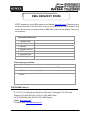
RMA REQUEST FORM
IDTECK accepts only on-line RMA requests on our Website (www.idteck.com). Please provide us
with basic information in the below form so that we can understand your problems better. Send
us back this form with your products after an RMA code is issued on our Website. This form is
not compulsory.
Authorization RMA Code :
1. Company Name
2. Model Name
3. Serial No.
4. Original Invoice No.
5. Distributor
6. Purchasing Date
7. RMA Request Date
Please check your problems.
□ Card Reading
□ Communication
□ LED & Buzzer
□ Power
.
.. □ Keypad
□ Relay
.
□ LCD
□ Registration
□ Others :
IDTECK RMA Center >>
3F, 10/10-1/10-2, Dodang-Dong, Weonmi-Gu, Bucheon-Si, Gyeonggi-Do 157-030, Korea
Telephone: 82.2.2659.0055 (HQ) / 82.32.671.5642 (RMA Center)
Fax: 82.2.2659.0086 (HQ) / 82.32.671.5641 (RMA Center )
Website: www.idteck.com
e-Training Center: www.idtecktraining.com
48
MEMO
49
MEMO
50
MEMO
51
The specifications contained in this manual are subject to change without notice at any time.
5F, Ace Techno Tower B/D, 684-1, Deungchon-Dong,
Gangseo-Gu, Seoul, 157-030, Korea
Tel : +82-2-2659-0055
Fax : +82-2-2659-0086
E-mail : [email protected]
MARFIN6HE31
May. 2008 Copyright © IDTECK Co., Ltd.


![PIN & 13.56MHz [MIFARE] Contactless Smart Card](http://vs1.manualzilla.com/store/data/005813586_1-ab1687ddb78fed02f4038390c7a52377-150x150.png)