1
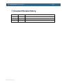
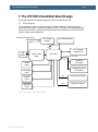
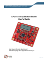
LPC11D14 QuickStart Board - User’s Guide Copyright 2012 © Embedded Artists AB LPC11D14 QuickStart Board User’s Guide Get Up-and-Running Quickly and Start Developing Your Applications On Day 1! EA2-USG-1106 Rev B LPC11D14 QuickStart Board - User’s Guide Page 2 Embedded Artists AB Davidshallsgatan 16 211 45 Malmö Sweden [email protected] http://www.EmbeddedArtists.com Copyright 2011-2012 © Embedded Artists AB. All rights reserved. No part of this publication may be reproduced, transmitted, transcribed, stored in a retrieval system, or translated into any language or computer language, in any form or by any means, electronic, mechanical, magnetic, optical, chemical, manual or otherwise, without the prior written permission of Embedded Artists AB. Disclaimer Embedded Artists AB makes no representation or warranties with respect to the contents hereof and specifically disclaim any implied warranties or merchantability or fitness for any particular purpose. Information in this publication is subject to change without notice and does not represent a commitment on the part of Embedded Artists AB. Feedback We appreciate any feedback regarding improvements on this document. Please send comments to [email protected]. Trademarks All brand and product names mentioned herein are trademarks, services marks, registered trademarks, or registered service marks of their respective owners and should be treated as such. Copyright 2012 © Embedded Artists AB LPC11D14 QuickStart Board - User’s Guide Page 3 Table of Contents 1 Document Revision History 4 2 Introduction 5 2.1 Features 5 2.2 ESD Precaution 6 2.3 General Handling Care 6 2.4 Code Read Protection 6 2.5 CE Assessment 6 2.6 Other Products from Embedded Artists 6 2.6.1 Design and Production Services 7 2.6.2 OEM / Education / QuickStart Boards and Kits 7 3 The LPC11D14 QuickStart Board Design 8 3.1 Block Diagram 8 3.2 Board Overview 9 3.3 Usage of CPU Pins 10 3.4 Schematic Walkthrough 11 3.4.1 Page 2 11 3.4.2 Page 3 11 3.4.3 Page 4 11 3.5 Default Jumper Positions 12 3.6 Things to Note about the Hardware 13 3.6.1 Rework Wire 4 Getting Started 14 4.1 Demo Application 14 4.2 Program Development 14 4.3 Compiling the Demo Application 14 4.4 Program Download 17 SWD Interface 17 4.4.1 4.4.2 4.4.3 4.5 Using LPCXpresso IDE/Debugger UART-ISP Console Interface via UART-to-USB Bridge 18 21 24 4.5.1 FTDI USB Driver 24 4.5.2 USB Driver Behavior 27 5 Further Information Copyright 2012 © Embedded Artists AB 13 28 LPC11D14 QuickStart Board - User’s Guide Page 4 1 Document Revision History Revision Date Description PA1 2011-11-17 First version of document. A 2011-11-24 Corrected minor errors in the text. B 2012-01-13 Added note about CE marking. Copyright 2012 © Embedded Artists AB LPC11D14 QuickStart Board - User’s Guide Page 5 2 Introduction Thank you for buying Embedded Artists’ LPC11D14 QuickStart Board based on NXP’s LPC11D14 ARM Cortex-M0 microcontroller with integrated LCD controller. This document is a User’s Guide that describes the LPC11D14 QuickStart Board hardware design. 2.1 Features Embedded Artists’ LPC11D14 QuickStart Board with NXP’s LPC11D14 microcontroller lets you get upand-running quickly. The small sized board offers many features that ease your learning curve and speed up your program development. The features of the LPC11D14 QuickStart Board are: NXP's LPC11D14 ARM Cortex-M0 microcontroller in 100-pin LQFP package, with 8 KByte internal SRAM and 32 Kbyte internal FLASH. 12.0000 MHz external crystal. The LPC11D14 runs at frequencies up to 50 MHz. With on-chip PLL the maximum frequency is 48MHz (PLL multiplies external crystal frequency by 4). All LPC11D14 pins available on expansion connector (100 mil/2.54 mm pitch dual rows around processor). UART-to-USB bridge interface to LPC11D14 UART Mini-B USB connector Proper ESD protection Support for automatic UART ISP program download Flexible powering, with on-board 800mA 3.3V voltage regulator Can be powered from USB connector, JTAG connector (if supported by JTAG debugger interface) or an external +5V supply LCD with 8 14-segment characters 32 Kbit I2C E2PROM for storing non-volatile parameters LM75 I2C temperature sensor Trimming potentiometer on analog input. 4 capacitive sensors. Onboard reset generation and reset push-button. Push-button for enabling Bootloader mode of the LPC11D14. Push-button for enabling start logic of the LPC11D14. Push-button for wakeup logic of the LPC11D14. Possibility to measure current consumption for LPC11D14 core, I/O and LCD controller parts individually. LED on pin PIO0_7. SWD/JTAG connector Copyright 2012 © Embedded Artists AB 2x5 pos, 50 mil/1.27 mm pitch, standard SWD/JTAG connector Pad for older 2x10 pos, 100 mil/2.54 mm pitch JTAG connector Compact size: 110 x 100 mm (W x H) LPC11D14 QuickStart Board - User’s Guide 2.2 Page 6 Four layer PCB design for best noise immunity ESD Precaution Please note that the LPC11D14 QuickStart Board come without any case/box and all components are exposed for finger touches – and therefore extra attention must be paid to ESD (electrostatic discharge) precaution. Make it a habit always to first touch the metal surface of the USB connector for a few seconds with both hands before touching any other parts of the board. That way, you will have the same potential as the board and therefore minimize the risk for ESD. Note that Embedded Artists does not replace boards that have been damaged by ESD. 2.3 General Handling Care Handle the LPC11D14 QuickStart Board with care. The board is not mounted in a protective case/box and is not designed for rough physical handling. Connectors can ware out after excessive use. The board is designed for evaluation and prototyping use, and not for integration into consumer or industrial end-products. The LPC11D14 QuickStart Board has an eight character LCD. Do not exercise pressure on the display glass area. That will damage the display. Note that Embedded Artists does not replace boards where the LCD has been improperly handled. 2.4 Code Read Protection The LPC11D14 has a Code Read Protection function (specifically CRP3, see LPC11D14 datasheet/user’s manual for details) that, if enabled, will make the LPC11D14 impossible to reprogram (unless the user program has implemented such functionality). Note that Embedded Artists does not replace boards where the LPC11D14 has CRP3 enabled. It’s the user’s responsibility to not invoke this mode by accident. 2.5 CE Assessment The LPC11D14 QuickStart Board is CE marked. See separate CE Declaration of Conformity document. The LPC11D14 QuickStart Board is a class B product. EMC emission test has been performed on the LPC11D14 QuickStart Board. The USB interface has been in use and also powered the device during the test. General expansion connectors where internal signals are made available (for example processor pins) have been left unconnected. Connecting other devices to the product via the general expansion connectors may alter EMC emission. It is the user’s responsibility to make sure EMC emission limits are not exceeded when connecting other devices to the general expansion connectors of the LPC11D14 QuickStart Board. Due to the nature of the LPC11D14 QuickStart Board – an evaluation board not for integration into an end-product – fast transient immunity tests and conducted radio-frequency immunity tests have not been executed. Externally connected cables are assumed to be less than 3 meters. The general expansion connectors where internal signals are made available do not have any other ESD protection than from the chip themselves. Observe ESD precaution. 2.6 Other Products from Embedded Artists Embedded Artists have a broad range of LPC1000/2000/3000/4000 based boards that are very low cost and developed for prototyping / development as well as for OEM applications. Modifications for Copyright 2012 © Embedded Artists AB LPC11D14 QuickStart Board - User’s Guide Page 7 OEM applications can be done easily, even for modest production volumes. Contact Embedded Artists for further information about design and production services. 2.6.1 Design and Production Services Embedded Artists provide design services for custom designs, either completely new or modification to existing boards. Specific peripherals and I/O can be added easily to different designs, for example, communication interfaces, specific analog or digital I/O, and power supplies. Embedded Artists has a broad, and long, experience in designing industrial electronics in general and with NXP’s LPC1000/2000/3000/4000 microcontroller families in specific. Our competence also includes wireless and wired communication for embedded systems. For example IEEE802.11b/g (WLAN), Bluetooth™, ZigBee™, ISM RF, Ethernet, CAN, RS485, and Fieldbuses. 2.6.2 OEM / Education / QuickStart Boards and Kits Visit Embedded Artists’ home page, www.EmbeddedArtists.com, for information about other OEM / Education / QuickStart boards / kits or contact your local distributor. Copyright 2012 © Embedded Artists AB LPC11D14 QuickStart Board - User’s Guide Page 8 3 The LPC11D14 QuickStart Board Design This chapter describes the hardware design of the LPC11D14 QuickStart Board. 3.1 Block Diagram The block diagram in Figure 1 below gives a quick overview of a design. It illustrates the major components in the design. The center of the design is the LPC11D14 MCU with integrated segment LCD controller from NXP. A number of external peripherals are connected to the LPC11D14 via I2C interface, analog inputs and digital I/O. External +5V power source VBUS +3.3V Voltage regulator SWD debug interface Current measurement 3.3V USB interface 8x 14-segment character LCD UART-to-USB bridge LPC11D14 I2C for internal LCD controller I2C Reset button Temperature sensor I2C interface ISP enable button Wakeup button Start logic button Figure 1 – LPC11D14 QuickStart Board Block Diagram Copyright 2012 © Embedded Artists AB E2PROM I2C interface AIN7 Trimming potentiometer AIN0-3 4 Capacitive sensors LPC11D14 QuickStart Board - User’s Guide 3.2 Page 9 Board Overview Figure 2 below illustrates the physical board structure. 14-segment character LCD UART-to-USB bridge interface Ground pad U3 – I2C temperature sensor U2 – I2C E2PROM Voltage measurement pads LPC11D14 current measurment Reset button Ground pad SWD interface JTAG interface (not mounted) R16 – trimming potentiometer Capacitive sensors Figure 2 – LPC11D14 QuickStart Board Overview Copyright 2012 © Embedded Artists AB LPC11D14 with pin access connectors SW2, SW3, SW4 LPC11D14 QuickStart Board - User’s Guide 3.3 Page 10 Usage of CPU Pins The table below lists which LPC11D14 pins that are used in the design. Many of the pins are free to use in customer extensions. All pins of the LPC11D14 are accessible via 100 mil pitch connectors around the chip on the pcb. LPC11D14 pin Usage PIO0_0 Reset PIO0_1 ISP enable push-button PIO0_2 Not used PIO0_3 Connected to Start Logic push-button. PIO0_4 I2C-SCL PIO0_5 I2C-SDA PIO0_6 Not used PIO0_7 Connected to LED. Active high. PIO0_8 Not used PIO0_9 Not used PIO0_10 SWD interface SWCLK PIO0_11 AIN0 – connected to capacitive sensor #0 PIO1_0 AIN1 – connected to capacitive sensor #1 PIO1_1 AIN2 – connected to capacitive sensor #2 PIO1_2 AIN3 – connected to capacitive sensor #3 PIO1_3 SWD interface SWDIO PIO1_4 Connected to Wakeup push-button PIO1_5 Not used PIO1_6 UART-RX, connected to uart-to-usb bridge PIO1_7 UART-TX, connected to uart-to-usb bridge PIO1_8 Not used PIO1_9 Connected to “555” circuit for emulation of an RC-timer PIO1_10 AIN6 – connected to “555” circuit for emulation of an RC-timer PIO1_11 AIN7 – connected to trimming potentiometer PIO2_0 to 2_11 Not used PIO3_0 to 3_5 Not used LCD signals Connected to 14-segment character LCD Copyright 2012 © Embedded Artists AB LPC11D14 QuickStart Board - User’s Guide 3.4 Page 11 Schematic Walkthrough 3.4.1 Page 2 The center of the board is the LPC11D14 from NXP. It is a MCU based on the ARM Cortex-M0 core. LPC11D14 has many power modes to save power consumption. See datasheet for details. It is possible to measure the current consumption of the LPC11D14, both VDDIO and VDDCORE. Normally both jumpers in JP5/JP6 are inserted but if removed there are 5 ohm resistors that can be used for measuring the current consumption. 10mA current will give a 50mV voltage drop over a 5 ohm resistor. On page 3 in the schematic there is also possibility to measure the current consumption to the integrated LCD controller. All pins of the LPC11D14 are directly accessible via JP1-JP4. These connection points are placed around the LPC11D14 chip on the board. J1 is the SWD interface for LPC11D14, i.e., debug interface. It is the new and smaller footprint standard ARM debug connector. It has 2x5 pins in 50 mil pitch. There are also pads, J2, for the older and bigger debug connector standard, the 2x10 pos, 100 mil pitch shrouded IDC connector. If needed, this connector can be mounted. SW1 is a start logic push button for waking the LPC11D14 from different low-power modes. Many pins can have this functionality. PIO0_3 has been selected for this board. SW2 is a wake-up push button for waking the LPC11D14 from ‘deep power down mode’. SW2 is connected to PIO1_4, which is the WAKEUP pin. A high-to-low transition on this pin will wake-up the LPC11D14 from ‘deep power down mode’. PIO1_4 is the only pin that can wake-up the LPC11D14 from this mode. 3.4.2 Page 3 The integrated segment LCD controller is a separate chip inside the LPC11D14 package. It is the PCF8576D chip that is used. The MCU communicates with the LCD controller via I2C. All pins from the LCD controller are connected to the 14-segment LCD on the board. It is possible to measure the current consumption of the PCF8576D. Normally a jumper in JP9 is inserted but if removed there are 5 ohm resistors that can be used for measuring the current consumption. 10mA current will give a 50mV voltage drop over a 5 ohm resistor. There is also a 32 kbit E2PROM and temperature sensor connected to I2C bus. The schematic show the I2C addresses of the different I2C devices. Details about the E2PROM, temperature sensor and LCD controller operations can be found in the respective datasheets. There are two on-board 2Kohm pull-up resistors (pull-ups are always needed on I2C busses). R16 is a 22K trimming potentiometer for simulating an arbitrary analog input signal. R16 is connected to analog input 7 (AD7), PIO1_11. There are four capacitive sensors connected to analog input 0-3 (PIO0_11, PIO1_0, PIO1_1, PIO1_2). NXP has published an application note about how to use the analog inputs of the LPC1100 family to create capacitive sensors. For compatibility with the LPC12D27 QuickStart board there is a “555” timer circuit also. This can be used to control an external RC oscillator. There is a LED connected to pin PIO0_7. A 1Kohm resistor limits the diode current to about 1.7mA. The LED will light when PIO0_7 is high. The PIO0_7 pin is a high-drive output capable of supplying up to 20 mA. See the datasheet for details. 3.4.3 Page 4 The UART-to-USB bridge is based on FT232RL and connects to the LPC11D14 UART. Functionality for automatic ISP activation is also included. This can be disabled by removing JP11 jumpers (which Copyright 2012 © Embedded Artists AB LPC11D14 QuickStart Board - User’s Guide Page 12 controls reset signal and bootload enable signal – PIO0_1). The USB interface is protected by ESD protection diode, D3. SW3 is a reset push-button connected to a voltage supervisor that generates proper reset pulses when needed. See datasheet of U7 for details. SW4 is an ‘ISP enable’ push-button. By pressing SW4 while resetting the LPC11D14 (pressing and releasing SW3) the In-System Programming (ISP) mode is entered. It is an internal boot loader mode of the LPC11D14. Communication takes place over the UART. Note that it can be useful to enter ISP mode if the application program has programmed the internal PLL:s wrong, or disabled the debug/SWD interface. In these situations, it can be impossible to get contact with the LPC11D14 via the debug/SWD interface. The application program can be erased while in ISP mode and a new, correct application program can be downloaded. The on-board 3.3V supply can be powered from the USB interface or from an external +5V supply. There is a LED that signals that +3.3V is present on the board. There are also two ground pads (TP4, TP5) for simplifying connection the ground cable of measurement devices, for example oscilloscope probes. 3.5 Default Jumper Positions The default positions for the 7 jumpers on the board are shown below. Note that some boards are incorrectly delivered with both jumpers in JP11 inserted. Figure 3 – LPC11D14 QuickStart Board Default Jumper Positions Copyright 2012 © Embedded Artists AB LPC11D14 QuickStart Board - User’s Guide 3.6 Page 13 Things to Note about the Hardware 3.6.1 Rework Wire Revision A of the board contains a layout error that affects the wakeup push-button (SW2). It is not connected to PIO1_4 as it should. This has been corrected on all boards via a red wire on the top side of the board. Figure 4 below shows where the rework wire is placed on the board. Figure 4 – LPC11D14 QuickStart Board with rework wire to SW2 Copyright 2012 © Embedded Artists AB LPC11D14 QuickStart Board - User’s Guide Page 14 4 Getting Started This chapter contains information about how to get acquainted with the LPC11D14 QuickStart Board. Please read this chapter first before start using the board - it will be well spent time! 4.1 Demo Application The board is preloaded with a demonstration application. This application begins with outputting a welcome message on the character LCD as well as over the UART. The LED on PIO0_7 is toggled and the four capacitive sensors are active. Touching one of the capacitive sensors will activate a sub application: 4.2 Cap sensor #0: Display the value of the trimming potentiometer Cap sensor #1: Display status of the 3 push buttons (SW1, SW2, SW4) Cap sensor #2: Display the reading from the I2C temperature sensor Cap sensor #3: Display the results of (startup) testing the I2C E2PROM Program Development This document does not contain information about how to write applications for the LPC11D14. For information about how to get started with program development in general, see the LPCXpresso IDE documentation: www.nxp.com/lpcxpresso. LPCXpresso is a concept from NXP, containing both a program development environment (LPCXpresso IDE) and target boards – LPCXpresso boards (jointly developed by Embedded Artists). The target boards also contain a SWD/JTAG interface, called the LPC-LINK. The LPCXpresso IDE is free and well-supported on the LPCXpresso forum. It is recommended to use for program development on the LPC11D14 QuickStart Board. The demo application for the LPC11D14 QuickStart Board can be downloaded from the Embedded Artists support site. This application has been developed in the LPCXpresso IDE. It is a good starting point for further development since it demonstrates all peripherals of the board and many features of the LPC11D14 processor. 4.3 Compiling the Demo Application This section describes how to compile the demo application. First make sure that the latest version of the LPCXpresso IDE is installed. Secondly, import the package containing the demo application into the Eclipse workspace. The package can be downloaded (as a zip-file) from Embedded Artists support page after registering the product. The zip-file contains all project files and is a simple way to distribute complete Eclipse projects. Select the Import and Export tab in the Quickstart menu and then Import archived projects (zip), see figure below. Copyright 2012 © Embedded Artists AB LPC11D14 QuickStart Board - User’s Guide Page 15 1) Select Import and Export 2) Select Import archived projects (zip) Figure 5 – LPCXpresso IDE Import Archived Project Next, browse and select the downloaded zip file containing the archived sample applications. Make sure all sub-projects are selected, see figure below. 1) Browse and select archived project file 2) Select all subprojects in list 3) Import project Figure 6 – LPCXpresso IDE Import Archived Project Window Copyright 2012 © Embedded Artists AB LPC11D14 QuickStart Board - User’s Guide Page 16 All sample projects are now imported. Click (to select) the project named ‘demo’. Browse and edit the project files. Build/clean/debug the project from the Quickstart menu (Start here), see picture below. 1) Click (to select) main project 2) Browse and edit project files 3) Build/clean/debug project Figure 7 – LPCXpresso IDE Build/Debug Project When debugging a project, make sure the LPC11D14 QuickStart Board is connected to the LPC-LINK debugger (see section 4.4 for a description). It is via LPC-LINK (SWD debug interface) that the application will be downloaded to the board. It is also via this interface that the actual debugging can take place by setting breakpoints, inspecting variable values, etc. Using the Debug project functionality is the normal way of downloading an application to the LPC11D14. Section 4.4 describes how to download an application (binary image/hex-file) in general, without debugging it. Sometimes an error message appears when trying to debug a project, i.e., download code. There are a couple of things to check: 1. Make sure last debug session has been ended. 2. Make sure the LPC-LINK is properly installed and connected. Especially check polarity of the small 10 pos SWD cable. Pin 1 in each end shall match each other. 3. Make sure that the LPC11D14 is in a mode where the debugger can take command over the processor. When the LPC11D14 is in a low-power mode it sometimes prohibits the debugger from connecting to the processor. The simplest way is to place the LPC11D14 in ISP/bootload mode. While resetting the LPC11D14 press the ISP Enable push-button. a. Press both Reset (SW3) and ISP push-button (SW4) b. Release the Reset push-button c. Release the ISP push-button d. The LPC11D14 is now in ISP/bootload mode. Copyright 2012 © Embedded Artists AB LPC11D14 QuickStart Board - User’s Guide 4.4 Page 17 Program Download There are two ways to download applications in to the LPC11D14. 4.4.1 SWD Interface The SWD interface is the recommended interface to use for program download since it also has the added benefit of being a debug interface useful during program development. How to use the debugger via LPCXpresso IDE is described in previous section 4.3 . Any SWD debug interface that supports ARM Cortex-M0 processors in general and the LPC1100 family in particular will work for downloading an application. Figure 8 below shows how the LPC-LINK (part of an LPCXpresso target board) is connected to the SWD interface of the LPC11D14 QuickStart Board. Note the orientation of the SWD cable. Pin 1 of the SWD connector in each end shall match each other. An LPC-LINK unit can be created by cutting any LPCXpresso target board into half – the half that contains the embedded debugger part. Figure 8 – LPC11D14 QuickStart Board connected to LPC-LINK, via SWD It is also possible to use the (physically) bigger 2x10 pos, 100 mil pitch ARM SWD/JTAG interface. Either solder a 2x10 pos, 100 mil pitch shrouded IDC connector to the LPC11D14 QuickStart Board or use Embedded Artists’ adapter for the purpose (article number: EA-ACC-040). See Figure 9 below. Note that the SWD/JTAG debug pod used must support the SWD protocol in order to work. Figure 9 – SWD/JTAG Adapter (EA-ACC-040) Copyright 2012 © Embedded Artists AB LPC11D14 QuickStart Board - User’s Guide 4.4.2 Page 18 Using LPCXpresso IDE/Debugger This section describes how to download an application to the board. 2. Connect the LPC-LINK to the LPC11D14 SWD interface. Use a 10 pos flat cable. Also make sure the LPC-LINK is connected to the PC via a USB cable. 3. Make sure that the LPC11D14 is in a mode where the debugger can take command over the processor. When the LPC11D14 is in a low-power mode it sometimes prohibits the debugger from connecting to the processor. The simplest way is to place the LPC11D14 in ISP/bootload mode. While resetting the LPC11D14 press the ISP Enable push-button. a. Press both Reset (SW3) and ISP push-button (SW4) b. Release the Reset push-button c. Release the ISP push-button d. The LPC11D14 is now in ISP/bootload mode. 4. Make sure that the latest version of the LPCXpresso IDE is installed on the PC. 5. Import the sample application software package into the Eclipse workspace. This package can be downloaded from the Embedded Artists support page after registering the product. The demo application is one of the projects in the sample application package. 6. Click on the "Program Flash" icon from the tool bar, see picture below. The icon can be at different places depending on window size. Program Flash Icon Figure 10 – LPCXpresso IDE Program Flash Icon The next step is to select which processor to download to. Select LPC1114/302 from the list that is presented. Then press OK button. Note that this step is sometimes not needed because the LPCXpresso IDE can itself detect which processor it is connected to. Note that LPC11D14 does not exist as a separate item in the list. This is because the LPC11D14 internally consists of two chips, one LPC1114 and one PCF8576D. Copyright 2012 © Embedded Artists AB LPC11D14 QuickStart Board - User’s Guide Page 19 The next step is to browse to the file to download. Press the “Browse” button. Figure 11 – LPCXpresso IDE Program Flash Window Browse to the projects top directory and then “Debug”. In this subfolder there is either a file ending with *.axf or *.bin. Select one of these files. Press the “Open” button. Note that screen shot below is generic and does not reflect the directory structure or folder names for the LPC11D14 demo application. 1) Find workspace and all sample apps. 2) Find project top directory 3) Find “Debug” subdirectory Figure 12 – Browse to File to Download Copyright 2012 © Embedded Artists AB 4) Select either *.axf or *.bin file LPC11D14 QuickStart Board - User’s Guide Page 20 Figure 13 – LPCXpresso IDE Program Flashing in Progress In case flashing fails, an error message like below will be displayed. This is an indication that the debugger could not connect to the LPC11D14. The most common reason is that the LPC11D14 was in a low-power mode where debug connection is not possible. Make sure the LPC11D14 is in ISP/bootload mode and try again. Also make sure the small 10-pos flat cable is connected between the LPC11D14 QuickStart Board and LPC-LINK. Figure 14 – LPCXpresso IDE Program Failing to Flash Copyright 2012 © Embedded Artists AB LPC11D14 QuickStart Board - User’s Guide Page 21 There is an alternative way of initiating the program download process. From the workspace, right click on the *.axf or *.bin file (found under the “Debug” subdirectory). Then select “Binary Utility” and “Program Flash”. 1) Right click on *.axf or *.bin file 2) Select “Binary Utility” 3) Select “Program Flash” Figure 15 – LPCXpresso IDE Binary Utility Press the reset push-button. The startup message from the demo application should be displayed on the LCD. 4.4.3 UART-ISP The other alternative for program download is to use In-System Programming (ISP) over the UART. Note that this method does not provide any debugging functionality. It is only for downloading a binary image (often called hex-file) to the board. If debugging via a debugger is needed, the SWD interface should be used instead. This section describes how to generate the hex file and then download the file to the LPC11D14 QuickStart Board. The LPC11D14 MCU samples the state of the PIO0_1 pin immediately after a reset. If the pin is low, the UART-ISP mode is activated. By pressing the ISP Enable/bootload push-button, SW4, pin PIO0_1 is pulled low. ISP mode is activated this way: 1. Press both the ISP Enable push-button (SW4) and the reset push-button (SW3). 2. Release the reset push-button while keeping the ISP Enable push-button pressed. 3. Then finally release the ISP Enable push-button. The LPC11D14 is now in UART-ISP mode. Copyright 2012 © Embedded Artists AB LPC11D14 QuickStart Board - User’s Guide Page 22 The sequence of steps can be done quickly. The minimum time between step 2 and 3 is in the region of 200mS (which is the reset pulse minimum time from U7 plus the time until the LPC11D14 samples the PIO0_1 pin). By inserting both jumpers in JP11, it is possible to control the reset signal and PIO0_1 signal via the UART interface (UART-to-USB bridge) instead of via the push-buttons. These are the steps to follow after both jumpers in JP11 have been inserted: 1. Download and install Flash Magic (http://www.flashmagictool.com/). Always use the latest version. 2. Build the application in the LPCXpresso IDE as mentioned in section 4.3 . 3. Open a command prompt in the directory containing the axf file. This can be done from the Utilities menu, see picture below. Figure 16 – LPCXpresso IDE Open Command Prompt 4. Convert the axf file to a hex file. In this example it is assumed that the sample application is named demo. arm-none-eabi-objcopy –O ihex demo.axf demo.hex Copyright 2012 © Embedded Artists AB LPC11D14 QuickStart Board - User’s Guide Page 23 5. Start Flash Magic, select correct Device, COM Port (the COM port associated with the target, section 4.5.1 describes the USB-to-UART bridge). Set baud rate to 38400, Interface to None and Oscillator to 12 MHz. Browse to the hex file to download, see picture below. Figure 17 – Flash Magic 6. Make sure the advanced options are correctly set. Select the Options menu and then select Advanced Options. Then select the Hardware Config tab. See picture below for correct settings in order for automatic ISP activation to work. Also not that both jumpers in JP11 must be inserted on the LPC11D14 QuickStart Board. Figure 18 – Flash Magic, Advanced Options – Hardware Config 7. Click the Start button and the application will be downloaded to the target. Copyright 2012 © Embedded Artists AB LPC11D14 QuickStart Board - User’s Guide 4.5 Page 24 Console Interface via UART-to-USB Bridge The LPC11D14 QuickStart Board contains a UART-to-USB bridge chip (FT232R from FTDI) that connects one of the UART channels on the LPC11D14 MCU to a virtual COM port on the PC (via USB). It is this serial channel that is the console interface to the system. Special USB drivers must be installed on the PC in order for the virtual COM port to be created. See subsection below for a description of how to install the FTDI USB driver. 4.5.1 FTDI USB Driver A USB driver must be installed on the PC computer in order to get the UART-to-USB chip (FT232R) to function. Make sure to download the latest version of the driver, which can be found at the following URL: http://www.ftdichip.com/Drivers/VCP.htm (search for a FT232R driver for the operating system on the PC). When the LPC11D14 QuickStart Board is connected to the PC (via an USB cable) the PC will ask for a driver. Unpack/unzip the downloaded driver file and browse to the position of the driver files. After successful driver installation, a COM port will be created. Before any communication with the Board can take place the UART settings must be correctly set. The following description is valid for Windows™ XP, but other operating systems have similar dialog windows. See the USB driver documentation for details, if needed. To change the UART settings, first open the System Properties dialog, as illustrated in the figure below. Device Manager Figure 19 – System Settings Dialog Then select the Device Manager and open the Ports list, as illustrated in Figure 20 – below. Copyright 2012 © Embedded Artists AB LPC11D14 QuickStart Board - User’s Guide Page 25 Ports Figure 20 – Device Manager Dialog The new COM port (USB Serial Port) will be listed under the Ports list. Right-click on the new USB Serial Port and select Properties, as illustrated in Figure 21 – below. USB Serial Port Properties Figure 21 – Device Manager Port Dialog Select 115200 bits per second, 8 data bits, none parity, 1 stop bit, and none flow control, as illustrated in Figure 22 – below. Then select Advanced settings. Please note that different application programs can use different baudrate settings for the serial channel. Other baudrates can also be used, depending on specific application. Copyright 2012 © Embedded Artists AB LPC11D14 QuickStart Board - User’s Guide Page 26 Also note that it is normally not needed to set the used baudrate at all. The driver and FT232R chip will automatically handle different baudrates. The setting is only shown here for completeness. UART settings Advanced settings Figure 22 – USB Serial Port Properties Dialog Select the desired COM port number under the Advanced settings dialog. Some terminal programs needs low COM port number, for example between 1 and 5. Very often the COM port number for the USB Serial Port is higher than this, therefore this need to be changed manually. It is common that all COM ports with low numbers are listed as occupied, but test to change to a low number anyway. Very often it is no problem at all to do so. COM Port Number Setting Figure 23 – Advanced USB Serial Port Properties Dialog Finally it is time to test if the USB Serial Port has been successfully installed and configured. Start a terminal program. Connect to the correct COM port, with 38400 bits per second, 8N1, no flow control. Copyright 2012 © Embedded Artists AB LPC11D14 QuickStart Board - User’s Guide 4.5.2 Page 27 USB Driver Behavior Sometimes the USB COM port does not enumerate properly when the board is connected to the PC. This is a known “feature” of the USB driver. If this problem occurs, just unplug the board shortly and then plug in again. A new COM port that can be accessed properly should be created the second time. This problem may occur after every time the PC is started (i.e., is power cycled). Copyright 2012 © Embedded Artists AB LPC11D14 QuickStart Board - User’s Guide Page 28 5 Further Information The LPC11D14 microcontroller is a complex circuit and there are a number of other documents with more information. The following documents are recommended as a complement to this document. [1] NXP’s product page for the LPC11D14 – contains links to datasheet, user’s manual, application notes and errata information http://www.nxp.com/products/microcontrollers/cortex_m0/lpc11d00/LPC11D14FBD100.html [2] LPCware is the NXP MCU community where a lot of information is posted about the processors http://www.lpcware.com/ [3] ARM Processor Documentation Documentation from ARM can be found at: http://infocenter.arm.com/. [4] Information on different ARM Architectures http://www.arm.com/products/processors/technologies/instruction-set-architectures.php [5] ARMv6-M Architecture Reference Manual. Document identity: DDI 0419B http://infocenter.arm.com/help/index.jsp?topic=/com.arm.doc.ddi0419b/index.html [6] Cortex-M0 Technical Reference Manual. Revision: r0p0 http://infocenter.arm.com/help/index.jsp?topic=/com.arm.doc.ddi0432c/index.html [7] LPCXpresso IDE: NXP's low-cost development platform for LPC families, which is an Eclipsebased IDE. http://ics.nxp.com/lpcxpresso/ [8] LPC1000 Yahoo Group. A discussion forum dedicated entirely to the NXP LPC1xxx series of microcontrollers. http://tech.groups.yahoo.com/group/lpc1000/ [9] LPC2000 Yahoo Group. A discussion forum dedicated entirely to the NXP LPC2xxx series of microcontrollers. This group might be more active than the LPC1000 group. http://tech.groups.yahoo.com/group/lpc2000/ Note that there can be newer versions of the documents than the ones linked to here. Always check for the latest information/version. Copyright 2012 © Embedded Artists AB