
1
EN
T
IG
TR
2D Code Reader V530-R2000 USER'S MANUAL
ES
C
2D Code Reader
S
T
HIF
D
P-2
-K LE
50 NSO
1
F O
C
V530-R2000
USER'S MANUAL
Authorized Distributor:
Cat. No. Q134-E1-01C
Note: Specifications subject to change without notice.
Printed in Japan
0106-0.1M (0903) (M)
Cat No. Q134-E1-01C
Thank you for purchasing the V530-R2000, which is also referred to as the Controller in
this manual. This manual explains how to use the Controller. Before attempting to use the
Controller, be sure to read this manual in its entirety, that you understand the information
provided, and that you use the Controller correctly. Keep this manual in a safe place so
that it is readily available for reference whenever needed.
OMRON Corporation
Industrial Automation Company
Application Sensor Division
Sensing Devices & Components Division H.Q.
Shiokoji Horikawa, Shimogyo-ku,
Kyoto, 600-8530 Japan
Tel : (81)75-344-7068 / Fax : (81)75-344-7107
Regional
Headquarters
____________________
OMRON EUROPE B.V.
Sensor Business Unit,
Carl-Benz-Str. 4, D-71154 Nufringen,
Germany
Tel : (49)7032-811-0 / Fax : (49)7032-811-199
OMRON ELECTRONICS LLC
1 East Commerce Drive, Schaumburg, IL 60173
U.S.A.
Tel : (1)847-843-7900 / Fax : (1)847-843-8568
OMRON ASIA PACIFIC PTE. LTD.
83 Clemenceau Avenue,
#11-01, UE Square,
239920 Singapore
Tel : (65)6835-3011 / Fax : (65)6835-2711
OMRON CHINA CO., LTD. BEIJING OFFICE
Room 1028, Office Building,
Beijing Capital Times Square,
No.88 West Chang'an Road,
Beijing, 100031 China
Tel : (86)10-8391-3005 / Fax : (86)10-8391-3688
Application Considerations
SECTION 1
Outline
SECTION 2
Installation and Connections
SECTION 3
Basic Operations
SECTION 4
Setting Read Conditions
SECTION 5
System Settings
SECTION 6
Optional Functions
SECTION 7
Host Communications
SECTION 8
Troubleshooting
SECTION 9
Appendix
2D Code Reader (Fixed)
USER'S MANUAL
V530-R2000
PREFIX SECTION
ÇÕǹÇ?Ç
ëÊ 1 ?Õ1 SECTION
ëÊ 2 ?Õ2 SECTION
ëÊ 3 ?Õ3 SECTION
ëÊ 4 ?Õ4 SECTION 5 SECTION 6 SECTION 7 SECTION 8 SECTION 9
PREFIX
PREFIX
PREFIX
APPLICATION CONSIDERATIONS
READ AND UNDERSTAND THIS DOCUMENT
APPLICATION CONSIDERATIONS
Please read and understand this document before using the products. Please consult your OMRON
representative if you have any questions or comments.
WARRANTY
OMRON’s exclusive warranty is that the products are free from defects in materials and workmanship for
a period of one year (or other period if specified) from date of sale by OMRON.
OMRON MAKES NO WARRANTY OR REPRESENTATION, EXPRESS OR IMPLIED, REGARDING
NON-INFRINGEMENT, MERCHANTABILITY, OR FITNESS FOR PARTICULAR PURPOSE OF THE
PRODUCTS. ANY BUYER OR USER ACKNOWLEDGES THAT THE BUYER OR USER ALONE HAS
DETERMINED THAT THE PRODUCTS WILL SUITABLY MEET THE REQUIREMENTS OF THEIR
INTENDED USE. OMRON DISCLAIMS ALL OTHER WARRANTIES, EXPRESS OR IMPLIED.
LIMITATIONS OF LIABILITY
OMRON SHALL NOT BE RESPONSIBLE FOR SPECIAL, INDIRECT, OR CONSEQUENTIAL
DAMAGES, LOSS OF PROFITS OR COMMERCIAL LOSS IN ANY WAY CONNECTED WITH THE
PRODUCTS, WHETHER SUCH CLAIM IS BASED ON CONTRACT, WARRANTY, NEGLIGENCE, OR
STRICT LIABILITY.
In no event shall responsibility of OMRON for any act exceed the individual price of the product on which
liability is asserted.
IN NO EVENT SHALL OMRON BE RESPONSIBLE FOR WARRANTY, REPAIR, OR OTHER CLAIMS
REGARDING THE PRODUCTS UNLESS OMRON’S ANALYSIS CONFIRMS THAT THE PRODUCTS
WERE PROPERLY HANDLED, STORED, INSTALLED, AND MAINTAINED AND NOT SUBJECT TO
CONTAMINATION, ABUSE, MISUSE, OR INAPPROPRIATE MODIFICATION OR REPAIR.
ii
V530-R2000
User’s Manual
PREFIX
OMRON shall not be responsible for conformity with any standards, codes, or regulations that apply to
the combination of products in the customer’s application or use of the product.
At the customer’s request, OMRON will provide applicable third party certification documents identifying
ratings and limitations of use that apply to the products. This information by itself is not sufficient for a
complete determination of the suitability of the products in combination with the end product, machine,
system, or other application or use.
The following are some examples of applications for which particular attention must be given. This is not
intended to be an exhaustive list of all possible uses of the products, nor is it intended to imply that the
uses listed may be suitable for the products:
• Outdoor use, uses involving potential chemical contamination or electrical interference, or conditions or
uses not described in this document.
• Nuclear energy control systems, combustion systems, railroad systems, aviation systems, medical
equipment, amusement machines, vehicles, safety equipment, and installations subject to separate
industry or government regulations.
• Systems, machines, and equipment that could present a risk to life or property.
APPLICATION CONSIDERATIONS
THE PRODUCTS CONTAINED IN THIS DOCUMENT ARE NOT SAFETY RATED. THEY ARE NOT
DESIGNED OR RATED FOR ENSURING SAFETY OF PERSONS, AND SHOULD NOT BE RELIED
UPON AS A SAFETY COMPONENT OR PROTECTIVE DEVICE FOR SUCH PURPOSES. Please refer
to separate catalogs for OMRON’s safety rated products.
PREFIX
SUITABILITY FOR USE
Please know and observe all prohibitions of use applicable to the products.
NEVER USE THE PRODUCTS FOR AN APPLICATION INVOLVING SERIOUS RISK TO LIFE OR
PROPERTY WITHOUT ENSURING THAT THE SYSTEM AS A WHOLE HAS BEEN DESIGNED TO
ADDRESS THE RISKS, AND THAT THE OMRON PRODUCT IS PROPERLY RATED AND INSTALLED
FOR THE INTENDED USE WITHIN THE OVERALL EQUIPMENT OR SYSTEM.
V530-R2000
User’s Manual
iii
PREFIX
PREFIX
PERFORMANCE DATA
APPLICATION CONSIDERATIONS
Performance data given in this document is provided as a guide for the user in determining suitability and
does not constitute a warranty. It may represent the result of OMRON’s test conditions, and the users
must correlate it to actual application requirements. Actual performance is subject to the OMRON
Warranty and Limitations of Liability.
CHANGE IN SPECIFICATIONS
Product specifications and accessories may be changed at any time based on improvements and other
reasons.
It is our practice to change model numbers when published ratings or features are changed, or when
significant construction changes are made. However, some specifications of the product may be
changed without any notice. When in doubt, special model numbers may be assigned to fix or establish
key specifications for your application on your request. Please consult with your OMRON representative
at any time to confirm actual specifications of purchased products.
DIMENSIONS AND WEIGHTS
Dimensions and weights are nominal and are not to be used for manufacturing purposes, even when
tolerances are shown.
ERRORS AND OMISSIONS
The information in this document has been carefully checked and is believed to be accurate; however, no
responsibility is assumed for clerical, typographical, or proofreading errors, or omissions.
PROGRAMMABLE PRODUCTS
OMRON shall not be responsible for the user’s programming of a programmable product, or any
consequence thereof.
COPYRIGHT AND COPY PERMISSION
This document shall not be copied for sales or promotions without permission.
This document is protected by copyright and is intended solely for use in conjunction with the product.
Please notify us before copying or reproducing this document in any manner, for any other purpose. If
copying or transmitting this document to another, please copy or transmit it in its entirety.égópÇ…ç¤Çµ
iv
V530-R2000
User’s Manual
PREFIX
PREFIX
PRECAUTIONS ON SAFETY
WARNING
Indicates a potentially hazardous situation which, if not avoided, will result in minor or
moderate injury, or may result in serious injury or death. Additionally there may be
significant property damage.
• Meanings of Alert Symbols
The following alert symbols are used in this document.
Indicates the possibility of explosion under specific conditions.
APPLICATION CONSIDERATIONS
• Meanings of Signal Words
The following signal words are used in this manual.
WARNING
Failure to read and understand the information provided in this manual may result in personal injury or
death, damage to the product, or product failure. Please read each section in its entirety and be sure you
understand the information provided in the section and related sections before attempting any of the
procedures or operations given.
V530-R2000
User’s Manual
v
PREFIX
PREFIX
• Alert statements in this Manual
The following alert statements apply to the products in this manual. Each alert statement also appears at
the locations needed in this manual to attract your attention.
APPLICATION CONSIDERATIONS
WARNING
A lithium battery is built into the V530-R2000 and may occasionally combust, explode, or
burn if not treated properly.
Dispose of the Controller as industrial waste, and never disassemble, apply pressure that
would deform, heat to 100°C or higher, or incinerate the V530-R2000.
A lithium battery is built into the V530-R2000 and may occasionally combust, explode, or
burn if not treated properly.
When replacing the battery, never short-circuit, attempt to charge, disassemble, apply
pressure that would deform, or incinerate the battery.
Regulations and Standards
The V530-R2000 complies with the international regulations and standards listed below.
EC Directives
EMC Directive: No.89/336/EEC
EN Standards (European Standards)
EN61326: 1997, +A1: 1998 +A2: 2001 (EMI: Class A)
Note: The length of Signal Cables should be less than 30 m.
The length of DC Power Supply Cables should be less than 10 m.
vi
V530-R2000
User’s Manual
PREFIX
PREFIX
Precautions for Safe Use
n Installation Environment Precautions
• Do not use the V530-R2000 in environments with flammable or explosive gases.
• Do not block the V530-R2000’s cooling vents.
Cooling vent
TRIG
POW
RESE
T
COM
IN
RUN
ER
RUN
Before the V530-R2000 is shipped, a protective label is attached to the top of the
V530-R2000 to cover the cooling vent.
This label prevents wire strands from falling
into the V530-R2000 during wiring. Do not
remove it until wiring is completed. The label must be removed after wiring to allow
proper cooling during operation.
V5302D COD
R2000
E REA
DER
ERR
OR
ERRO
R
NG
BUSY
NC
ALAR
M
COMO
UT
CONSO
LE
MEMORY CARD
CAM
ERA
0
RS-232
CAME
C/422
RA 1
MONIT
OR
APPLICATION CONSIDERATIONS
Observe the following precautions to ensure safe use of the product.
+
24V
-1.2ADC
Cooling vent
• Install the V530-R2000 away from high-voltage devices and moving machinery to
allow safe access during operation and maintenance.
• Be sure to securely tighten the screws when mounting the V530-R2000.
n Power Supply and Wiring Precautions
• Use the V530-R2000 with the power supply voltages specified in this manual.
• Use the wire and crimp terminals of the proper sizes as specified in this manual. Do
not connect the power supply wires by just twisting stranded wires and connecting
them directly to the terminals.
• Keep the power supply cable as short as possible (10 m maximum).
• Use a DC power supply with countermeasures against high-voltage spikes (safe
extra low-voltage circuits on the secondary side).
p.15
• Use an appropriate ground (100 Ω maximum).
• Use a grounding point as close as possible to the V530-R2000 and keep the ground
line as short as possible.
• Wire the V530-R2000 to the ground with a separate ground wire. To avoid grounding
problems, do not share the ground wiring with any other devices or ground the V530R2000 to the building’s steel framing or plumbing.
p.14
V530-R2000
User’s Manual
vii
PREFIX
PREFIX
n Connectors
Do not remove the connector cover. Doing so may cause product failure.
POW
RESE
T
ER
RUN
COMI
V530-
2D COD
R2000
E REA
DER
N
ERR
OR
RUN
ERRO
R
NG
BUSY
NC
ALAR
M
COMO
UT
MEMORY CARD
APPLICATION CONSIDERATIONS
TRIG
CONSO
LE
CAM
ERA
Connector
cover
0
RS-232
C/422
CAME
RA 1
MONIT
OR
+
24V
-1.2ADC
n Other Precautions
• Do not attempt to disassemble, repair, or modify the V530-R2000. Doing so may
cause product failure or a fire.
• If you suspect an error or malfunction, stop using the V530-R2000 immediately, turn
OFF the power supply, and consult your OMRON representative.
viii
V530-R2000
User’s Manual
PREFIX
PREFIX
Precautions for Correct Use
effects on performance or devices.
Controller Installation Site
n Do NOT install the V530-R2000 in locations subject to the following conditions:
• Ambient temperatures outside of 0 to 50°C (32 to 122°F)
• Rapid temperature fluctuations (likely to cause condensation)
• Relative humidity outside of 35% to 85%
• Presence of corrosive or flammable gases
APPLICATION CONSIDERATIONS
Observe the following precautions to prevent operation from failing, malfunctions, or adverse
• Presence of dust, salt, or iron particles
• Direct vibration or shock
• Direct sunlight
• Water, oil, chemical fumes, or chemical spray
n Mounting Orientation
To improve heat dissipation, install the Controller in the following orientation only:
Correct
TRIG
POWE
R
RESET
COM
RUN
IN
V530
2D COD-R20
E REA 00
DER
ERRO
RUN
R
ERROR
NG
BUSY
NC
MEMORY CARD
ALAR
M
COMOUT
CONS
OLE
CAME
RA 0
RS-23
CAME
2C/42
2
RA 1
MONIT
OR
+
24
VD
-1.2A C
Do not install the Controller in the orientations shown in the following diagrams.
Incorrect
ALARM
NC
CAMERA 0
24VDC
1.2A
+
MONITOR
COMOUT
CONSOLE
2D CODE READER
BUSY
NG
V530-R2000
RUN
POWER
ERROR
ERROR
RUN
COMIN
RESET
TRIG
CAMERA 1
RD
RY CA
MEMO
-
RS-232C/422
Incorrect
V530-R2000
User’s Manual
ix
PREFIX
PREFIX
n Ambient Temperature
• Maintain a minimum clearance of 50 mm above
Control box
and below the V530-R2000 to improve air circula-
APPLICATION CONSIDERATIONS
tion.
• Do not install the V530-R2000 immediately above
significant heat sources, such as heaters, transformers, or large-capacity resistors.
Controller
• Do not let the ambient operating temperature
exceed 50°C (122°F).
Louver
• Provide a forced-air fan or air conditioning if the
ambient temperature is near 50°C (122°F) so that the ambient temperature never
exceeds 50°C (122°F).
n Noise Resistance
• Do not install the V530-R2000 in a cabinet containing high-voltage equipment.
• Do not install the V530-R2000 within 200 mm of
Power cable
200 mm min.
power cables.
200 mm min.
Controller
x
V530-R2000
User’s Manual
PREFIX
PREFIX
Component Installation and Handling
Be sure to use the Camera, Camera Cable, and Console designed for the V530R2000.
p.6
n Cameras and Cables
Always turn OFF the power supply before connecting or disconnecting Cameras or
Cables.
n Cameras
APPLICATION CONSIDERATIONS
n OMRON Components
The Camera's case is connected to the 0 V line in the internal circuits. Observe the following precautions to prevent noise interference.
• Do not ground the Camera.
• Do not remove the base attached to the Camera.
• Do not remove the core attached to the F150-VS-2D Camera Cable.
n Video Monitor
When using the recommended F150-M09-2D Monitor, observe the following precautions to prevent noise interference. The Video Monitor case is connected to the 0 V line
in the internal circuits.
• Do not ground the Video Monitor.
• Do not ground the metallic part of the connector.
• Secure the Video Monitor with plastic screws if it is being mounted to a metallic surface.
n Touching Signal Lines
To prevent damage from static electricity, use a wrist strap or another device for preventing electrostatic discharges when touching terminals or signal lines in connectors.
n Memory Cards
Do NOT remove the Memory Card when the Memory Card indicator is lit.
The Memory Card or the Controller may be damaged.
p.53
V530-R2000
User’s Manual
xi
PREFIX
PREFIX
n Turning OFF the Power Supply
Do not turn OFF the power supply while a message is being displayed indicating that
processing is being performed. Data in memory will be destroyed, and the V530-R2000
APPLICATION CONSIDERATIONS
may not operate correctly the next time it is started.
Teaching
Executing
(ESC:Cancel)
n Using the RESET Signal
Do not use the RESET input immediately after power is turned ON. When using the
RESET input to synchronize execution timing, wait at least 1 second after turning ON
the V530-R2000 power supply before turning ON the RESET signal.
xii
V530-R2000
User’s Manual
PREFIX
PREFIX
Visual Aids
Visual Aids
Indicates points that are important in using product functions or in application procedures.
Indicates where to find related information.
Indicates information helpful in operation.
Screen Messages
In this manual, screen messages and menu commands are given in bold.
Example:
System Set. (System Settings)
System Set./Com Mode indicates the levels in the menu.
Trademarks: CompactFlash is a registered trademark of SanDisk.
V530-R2000
User’s Manual
xiii
PREFIX
PREFIX
Table of Contents
APPLICATION CONSIDERATIONS
Table of Contents
Visual Aids
xiii
Table of Contents
xiv
SECTION 1 Outline
1
Functions
SECTION 2 Installation and Connections
2
5
Basic System Configuration
6
Component Names and Functions
8
Mounting the Controller
9
Connecting Peripheral Devices
13
Power Supply and Ground
14
SECTION 3 Basic Operations
17
Flow of Operations
18
Starting the Controller
19
Ending Operation
22
Basic Knowledge of Operations
23
SECTION 4 Setting Read Conditions
27
Executing Teaching
28
Changing Read Conditions
30
Switching Read Conditions
32
Deleting Read Conditions
33
Using Analytical Functions
34
SECTION 5 System Settings
xiv
ii
39
Setting the Communications Mode
40
Setting Communications Conditions
42
Setting the Trigger Mode
43
Camera and Lighting Settings
45
V530-R2000
User’s Manual
PREFIX
47
48
Checking Read Images
54
Changing the Conditions for Storing Images
55
Backing Up Watcher Data in Memory Cards
56
Checking the Version
57
Changing the Language between Japanese and English
58
SECTION 7 Host Communications
59
Serial Interface
60
I/O Terminals
85
SECTION 8 Troubleshooting
95
Error Messages and Corrections
96
Error Messages and Corrections
97
Troubleshooting
97
2D Code Checker and Condition Watcher
99
SECTION 9 Appendix
Table of Contents
Backing Up Data in Memory Cards
PREFIX
SECTION 6 Optional Functions
101
Lens and Lighting
102
Line Speed, Reading Time, and Shutter Speed
111
Maintenance
113
Specifications and Dimensions
115
ASCII Table
126
FCS Check Programming Examples (BASIC)
127
Data Capacity Tables
129
Menu Structure
132
Index
133
Revision History
135
V530-R2000
User’s Manual
xv
PREFIX
PREFIX
Table of Contents
xvi
V530-R2000
User’s Manual
This section introduces the functions and operational flow of the Controller.
Functions
SECTION 1 Outline
SECTION 1
Outline
2
V530-R2000
User's Manual
1
SECTION 1
Outline
Functions
SECTION 1 Functions
n Setting Conditions by Teaching
Read conditions can be set by using the results of reading a sample of the code prepared in advance. Read conditions are set according to the code to be read, making
reading more stable and shortening reading time.
p.28
Teaching
Executing
(ESC: Cancel)
n Analytical Functions
The quality of code images can be checked and ongoing reading stability can be monitored. There are two analytical functions, the 2D Code Checker and the Condition
Watcher. Information based on the purpose of each function is displayed on the Read
Screen. If reading quality diminishes, an alarm is displayed on the Monitor and output
via an output terminal or communications.
p.34
2D Code Checker
Condition Watcher
Still
Set.# 1
Light
550msec
Still
Point 24
100
55
79
69
90
90
64
1.Light
2.Focus
3.Mark
4.Locate
5.Size
6.B.G.
6
Make lighting brighter
4
3
Appraised items
V530-R2000
User’s Manual
1000
500
ALM Make lighting brighter
OMRON2002
GL
GL
OMRON2002
2
0
2
5
ALM
50
1
OMRON2002C R
OMRON2002C R
Total 1635
OK
1602
Alarm 30
NG
3
Continuous reading transition graph
SECTION 1
Outline
n Reading Heads
There are three models of Reading Head, each of which integrates lighting with a zoom
lens. If a Reading Head is used and teaching is performed, optimization is possible for
p.103
Reading Head with
Oblique/Coaxial Lighting
V530-L2001
Reading Head with
Ring Lighting
V530-L2002
Reading Head with
V-type Coaxial Lighting
V530-L2003
Provides oblique/coaxial lighting
arranged at various angles. Suitable for wafers, liquid crystal
glass, PDP glass, electronic components, and many other types of
workpiece.
Diffuse lighting arranged in a ring
is used to read regular reflections
from a code. This system is ideal
for reading 2D codes that have
been embossed in engine parts or
other metal parts.
A regular reflective optical system
that does not produce interference
is used with diffuse light from a
large opening. These, along with
the ability to handle a large skew
angle, makes the Reading Head
ideal for reading codes from
objects with mirrored surfaces,
such as wafers.
SECTION 1 Functions
the lighting direction for the V530-L2001 or the lighting color for the V530-L2003.
n Readable Codes
Readable Codes
Readable sizes
(symbol size)
DataMatrix
QR Code
• ECC200
10 × 10 to 64 × 64
8 × 18 to 16 × 48
• Model 1 or 2
21 × 21 to 57 × 57
(Version 1 to Version 10)
V530-R2000
User’s Manual
3
SECTION 1
Outline
n Backing Up Data to Memory Cards
A Memory Card slot is provided to back up settings, read images, and monitoring information on Memory Cards. This data can be uploaded to the Controller except for read
SECTION 1 Functions
images.
p.21, p.48
MEMORY CARD
128MB
n Connect Up To Two Cameras
Up to two Cameras can be connected to each Controller to enable reading and processing two locations.
Controller
The two Cameras cannot be used simultaneously. Select the Camera to be used.
p.45
4
V530-R2000
User’s Manual
SECTION 2
Installation and Connections
devices.
Basic System Configuration
6
Component Names and Functions
8
Mounting the Controller
9
Connecting Peripheral Devices
13
Power Supply and Ground
14
V530-R2000
User's Manual
SECTION 2 Installation and Connections
This section explains how to install the Controller and connect the peripheral
5
SECTION 2
Installation and Connections
Basic System Configuration
A basic configuration is shown below.
Components marked with an asterisk are specifically designed for the V530-R2000. Other products cannot
be used. (Using other products may damage other components in the system.)
SECTION 2 Basic System Configuration
*Console
F150-KP-2D
(Cable length: 2 m)
ESC
Controller
TRIG
ENT
V530-R2000
POWER
RUN
TRIG
2D CODE READER
SHIFT
RESET
ERROR
COMIN
MEMORY CARD
RUN
ERROR
NG
BUSY
NC
ALARM
CONSOLE
CONSOLE
COMOUT
CAMERA0
RS-232C/422
*Camera Cable
F150-VS-2D (3 m)
CAMERA1
Power supply
p.15
MONITOR
+
24VDC
-
Recommended model:
OMRON S82K-05024
6
V530-R2000
User’s Manual
Monitor Cable
F150-VM-2D (2 m)
SECTION 2
Installation and Connections
SECTION 2 Basic System Configuration
*Camera
*Reading Heads
Integrate the lighting and lens.
The Camera captures an image of
the workpiece.
Up to 2 Cameras can be connected
to a V530-R2000.
p.103
V530-L2001
• Camera Only
A standard CCTV lens and lighting
will be needed.
V530-L2002
F160-S2-2D
V530-L2003
*Monitor
The Monitor is used to check the images and display menus when making settings.
• Liquid Crystal Monitor (Color)
F150-M05L-2D
• Video Monitor (Monochrome)
CRT
F150-M09-2D
POWER
SYNC
BNC jack
(Provided with the
F150-VM-2D
Monitor Cable.)
(Pin input)
(BNC input)
V530-R2000
User’s Manual
7
SECTION 2
Installation and Connections
Component Names and Functions
Console Connector p.13
POWER Indicator
Lit while power is ON.
Memory Card Indicator p.53
ERROR Indicator
Lit when an error
occurs.
I/O Terminals p.85
V53
0
ER 2D CO -R200
TRIG
POW
RESE
T
COMI
N
RUN
RUN
Memory Card Slot p.52
DE RE 0
ADER
ERR
OR
ERRO
R
NG
BUSY
NC
ALAR
M
COMO
MEMORY CARD
SECTION 2 Component Names and Functions
RUN Indicator
Lit when the Read
Screen is displayed.
UT
CON
SOLE
CAM
ERA
Battery Cover p.113
0
Card Lock p.52
RS-2
CAM
Camera
Connectors
p.13
Power Supply
Terminals p.15
ERA
32C/4
22
1
MON
ITOR
+
-
24V
DC
RS-232C/422 Connector p.60
Monitor Connector p.13
8
V530-R2000
User’s Manual
Ground Terminal p.14
SECTION 2
Installation and Connections
Mounting the Controller
There are four ways to mount the Controller: DIN Track mounting, rear surface mounting, side
surface mounting, and bottom surface mounting.
The Controller can be easily mounted to or removed from 35-mm DIN Track.
TRIG
RESET
COMIN
RUN
ERROR
NG
BUSY
NC
ALARM
COMOUT
DIN Track (OMRON)
PFP-100N (1 m)
PFP-50N (50 cm)
PFP-100N2 (1 m)
PFP-N End
Plate (OMRON)
SECTION 2 Mounting the Controller
DIN Track Mounting
n Mounting the Controller
Hook the V530-R2000 into the DIN Track as shown in the diagram and then press in at
the bottom until the V530-R2000 locks into place.
n Removing the Controller
Use a screwdriver to pull the hook down and then pull out the V530-R2000 from the
bottom.
TRIG
RESET
COMIN
RUN
ERROR
NG
BUSY
NC
ALARM
COMOUT
V530-R2000
User’s Manual
9
SECTION 2
Installation and Connections
Rear Surface Mounting
the Mounting Bracket to the V530-
R2000 Controller using the four machine
POWE V530-R
R 2D COD 2000
E REA
DER
TRIG
screws (M3 x 6) provided with the Bracket.
RES
ET
COM
RUN
IN
ERRO
RUN
R
ERR
OR
NG
BUS
Y
NC
ALA
RM
COM
MEMORY CARD
SECTION 2 Mounting the Controller
1. Attach
OUT
CONS
OL
E
CAME
RA 0
RS-23
CAME
2C/42
2
RA 1
MONIT
OR
+
-
24VD
C
2. Secure the V530-R2000 Controller and Mounting Bracket to the mounting surface with four
M4 screws.
POWE V530-R
R 2D CO 2000
TRIG
RES
ET
DE RE
ADER
RUN
COM
IN
ERRO
RUN
ERR
OR
R
NG
BUS
Y
NC
RM
COM
OUT
CONS
CAME
OLE
MEMORY CARD
ALA
RA 0
Dimensions
RS-23
2C/42
2
CAME
RA 1
(Unit: mm)
45±0.2
Four M4 holes
MONIT
OR
+
180±0.2
(190)
-
(62.2)
10
V530-R2000
User’s Manual
24VD
C
SECTION 2
Installation and Connections
Side Surface Mounting
SECTION 2 Mounting the Controller
POWE
R 2D CO
TRIG
RES
ET
RUN
COM
IN
DE RE
ADER
ERRO
R
RUN
ERR
OR
NG
BUS
Y
NC
ALA
RM
COM
OUT
CONS
OLE
CAME
RA 0
RS-23
CAME
2C/42
2
RA 1
MONI
TOR
+
-
24VD
C
Dimensions
(12)
60±0.4
(Unit: mm)
(7)
66.5±0.4
66.5±0.4
(153)
Four M3 holes (Screw depth: 4.8 mm max.)
(110)
V530-R2000
User’s Manual
11
SECTION 2
Installation and Connections
Bottom Surface Mounting
SECTION 2 Mounting the Controller
V5
POWE 2D 30-R
2000
CO
R
TRIG
RES
ET
COM
DE RE
ADER
RUN
IN
ERRO
RUN
R
ERR
OR
NG
BUS
Y
NC
ALA
RM
COM
OUT
CONS
OLE
CAME
RA 0
RS-23
CAME
2C/42
2
RA 1
MONI
TOR
+
-
24VD
C
Dimensions
38±0.3
(Unit: mm)
(9)
12
V530-R2000
User’s Manual
92±0.5
Four M4 holes
(Screw depth: 6 mm max.)
SECTION 2
Installation and Connections
Connecting Peripheral Devices
This section shows how to connect peripheral devices to the V530-R2000.
Turn OFF the power to the V530-R2000 before connecting or disconnecting Cables. Peripheral devices can
be damaged if connected or disconnected with the power supply turned ON. The connectors are capped
when the V530-R2000 is shipped. When not using a connector, leave the cap in place to protect against dust,
dirt, and static electricity.
SECTION 2 Connecting Peripheral Devices
Connecting a Camera
Connect the Camera Cable to the CAMERA connector on the V530-R2000.
CAMERA 0
Lens and Lighting p.102
Connecting a Console
Connect the Console to the CONSOLE connector on the V530-R2000.
ESC
TRIG
ENT
SHIFT
CONSOLE
F150-KP-2D
CONSOLE
Connecting the Monitor
Connect the Monitor Cable to the MONITOR connector on the V530-R2000, and attach
the enclosed ferrite core to the Monitor Cable. The ferrite core should be attached to
the Cable approximately 10 mm from the MONITOR connector.
MONITOR
Approx. 10 mm
Ferrite core
Wrap one loop of the cable
around the ferrite core.
V530-R2000
User’s Manual
13
SECTION 2
Installation and Connections
Power Supply and Ground
Wire the power supply and the ground, and tighten the screws to a torque of 0.5 N·m. After
wiring, check to make sure that the wiring is correct.
SECTION 2 Power Supply and Ground
Crimp Terminals and Cables
The terminal block uses M3 terminal screws. Use appropriate crimp terminals for M3
screws, as shown below.
Recommended Models
Terminal shape
Forked
6.2 mm max.
Round
6.2 mm max.
Manufacturer
Model
J.S.T. Mfg Co.,
Ltd.
V1.25-N3A
J.S.T. Mfg Co.,
Ltd.
V1.25-MS3
Recommended
wire size
1.31 to 1.65 mm2
(AWG15 to
AWG16)
Wiring the Ground
Be sure to wire the ground to a independent ground pole. To avoid damage to the
equipment, do not share the ground pole with any other devices and do not wire the
ground terminal to a girder. Keep the ground line as short as possible.
V530-R2000
Connect the ground terminal to 100 Ω max.
14
V530-R2000
User’s Manual
SECTION 2
Installation and Connections
Wiring the Power Supply
Wire the Power Supply Unit independently of other devices. In particular, keep the
power supply wired separately from inductive loads.
Use a power supply with the following specifications.
Requirements
Power supply voltage
1.6 A min.
20.4 to 26.4 VDC
SECTION 2 Power Supply and Ground
Output current
Recommended Model
Model
S82-K05024
Use a DC power supply with safe extra-low-voltage circuits on the secondary side.
If UL recognition is required for the overall system, use a UL class II power supply.
V530-R2000
2D CODE READER
24VDC
24 VDC
• Keep the power supply cable as short as possible (10 m max.).
Cover the power supply with the terminal block cover. Attach the terminal block cover in its original
position after completing wiring. Be careful not to loose the terminal block cover when removing it.
24VDC
Terminal block cover
(transparent)
V530-R2000
User’s Manual
15
SECTION 2
MEMO
16
V530-R2000
User’s Manual
SECTION 3
Basic Operations
This section describes the basic menu operations.
18
Starting the Controller
19
Ending Operation
22
Basic Knowledge of Operations
23
Input Keys
23
Description of the Read Screen
24
Navigating Menu Levels
25
Selecting and Confirming Items
26
Inputting Numbers
26
V530-R2000
User's Manual
SECTION 3 Basic Operations
Flow of Operations
17
SECTION 3
Basic Operations
Flow of Operations
Turn ON the power supply.
Starting for the first time.
Select the display language (Japanese or English).
p.19
Copy settings from Another Controller as required.
p.21
Basic Operations before Reading
SECTION 3 Flow of Operations
Setting Conditions and Reading
Execute teaching.
p.28
Change read conditions if necessary.
p.30
Start reading.
p.24
System Settings
Set the Camera and lighting conditions.
p.45
Set the host communications specifications and I/O format.
p.39, 59
Options
Use the analytical functions.
p.34
Check the read image.
p.54
Back up images, read conditions, and system data.
p.48
Saving Settings
Save settings before turning OFF the power.
p.22
Problems?
18
V530-R2000
User’s Manual
Error messages and error codes
p.96
Troubleshooting
p.97
SECTION 3
Basic Operations
Starting the Controller
The following procedure is used to access the menus.
1. Be sure that the basic system components have been connected correctly.
p.6
ESC
TRIG
ENT
SECTION 3 Starting the Controller
Console
V530-R2000
2D CODE READER
SHIFT
CONSOLE
Camera
POWER
Monitor
SYNC
Power supply
2. Turn ON the power supply to the Monitor.
3. Turn ON the power supply to the V530-R2000.
When starting the Controller for the first time, a screen
to select the language will be displayed after the initial
screen.
Do not input the RESET signal or turn OFF the
power supply while the initial screen is being
English
Japanese
displayed. Data may be corrupted, preventing
normal operation the next time the Controller is
started.
4. Move the cursor to English and press the
ENT Key.
V530-R2000
User’s Manual
19
SECTION 3
Basic Operations
The Start Setting Screen will be displayed.
5. Select Start Setting to set the conditions
Start Setting
Upload Settings
from the beginning.
Select Upload Settings to use settings uploaded from
another Controller.
p.21
SECTION 3 Starting the Controller
The Menu Screen will be displayed.
Menu
6. Set the read conditions.
Refer to SECTION 4 Setting Read Conditions.
Read Set.
System Set.
Option
Language
Save
After setting the read conditions and before turning OFF the power supply, save the settings in the
flash memory in the Controller.
p.22
If data has been saved in flash memory, the screens in steps 4. to 6. will not be displayed and the
Read Screen will be displayed instead.
20
V530-R2000
User’s Manual
SECTION 3
Basic Operations
Copying Settings from Another Controller
1. Insert the Memory Card to which the settings
Start Setting
Upload Settings
have been backed up.
2.
Select Upload Settings.
SECTION 3 Starting the Controller
The System Data Selection Screen will be displayed.
3. Move the cursor to the data containing the
settings to be uploaded and press the ENT
Key.
/c0/SYSTEM
[.
]
[..
]
030416
SYD
030416-1 SYD
030416-2 SYD
030416-3 SYD
030416-4 SYD
03/04/16
03/04/16
03/04/16
03/04/16
03/04/16
03/04/16
03/04/16
/c0/READCOND
[.
]
[..
]
030416
RDA
030416-1 RDA
03/04/16
03/04/16
03/04/16
03/04/16
The Read Conditions Selection Screen will be displayed.
4. Move the cursor to the data containing the
settings to be uploaded and press the ENT
Key.
The Read Screen will be displayed.
Still
ESC : Live
TRIG: Read
ENT: Menu
V530-R2000
User’s Manual
21
SECTION 3
Basic Operations
Ending Operation
Before turning OFF the power supply, save the settings in the flash memory in the Controller.
The Controller will load the settings contained in the flash memory every time it is started. If the power supply
is turned OFF without saving any changes to the settings in flash memory, the changes will be lost. Stored
images cannot be saved in flash memory and will be cleared when the power supply is turned OFF. To keep
from loosing stored images, back them up in a personal computer or on a Memory Card.
p.48
SECTION 3 Ending Operation
Menu
Read Set.
System Set.
1. Select Save from the Menu Screen.
Option
Language
Save
The Save Screen will be displayed along with a confirmation message.
Save
All Settings will be saved.
Do you execute?
2. Select OK.
OK
Cancel
Do not input the RESET signal or turn OFF the power supply while a message is being displayed
indicating that data save or load processing is being performed. Data may be corrupted, preventing
normal operation the next time the Controller is started.
The screen in 1. will return when the data has been saved.
3. Turn OFF the power supply to end operation.
22
V530-R2000
User’s Manual
SECTION 3
Basic Operations
Basic Knowledge of Operations
Input Keys
Menu operations are performed using the Console.
TRIG (trigger) Key
TRIG
ENT
ENT (enter) Key
Up, Down, Left, and Right Keys
SHIFT
SHIFT Key
CONSOLE
V530-R2000
User’s Manual
SECTION 3 Basic Knowledge of Operations
ESC
ESC (escape) Key
23
SECTION 3
Basic Operations
Description of the Read Screen
This screen is used to receive triggers and execute reading. This is thus the main
screen.
Still
SECTION 3 Basic Knowledge of Operations
1
No.
2
ESC : Live TRIG: Read ENT: Menu
Display item
Description
1
Key functions
Gives the functions of the Console Keys on the displayed screen.
2
Image display
status
Still: The still image that was read is displayed.
Live: The current image read by the Camera is displayed in real-time.
The Read Screen will switch between a still and live image each time the ESC
Key is pressed.
If reading is performed when a live image is being displayed, the start of reading the image may be delayed depending on the input timing of the command.
Display a still image when reading moving workpieces.
When reading is executed, the key descriptions (1) will disappear and the reading results will be displayed.
24
V530-R2000
User’s Manual
SECTION 3
Basic Operations
Navigating Menu Levels
This section describes how to display menu commands and how to move between
menu levels.
Still
1. Press the ENT Key on the Read Screen.
TRIG: Read
ENT: Menu
The Menu Screen will be displayed.
Menu
2. Move the cursor to the item to be set.
Up/Down Keys: Move the cursor up and down.
Read Set.
System Set.
Option
Language
Save
Teaching
Read Condition
Watcher Function
3. Press the ENT Key.
A submenu will be displayed if the cursor is moved to a
menu item with a triangle and the ENT Key or Right
Key is pressed.
The setting screen for the selected item will be displayed.
Submenu
SECTION 3 Basic Knowledge of Operations
ESC : Live
Screen when Read Set./Watcher Function Is
Selected
Watcher Function
Watcher Function : ON
Display Mode
: Watcher
Com Alarm
: ON
History
Clear
OK
Cancel
If the ESC Key is pressed in the Menu Screen for 2. the Read Screen for 1. will return.
V530-R2000
User’s Manual
25
SECTION 3
Basic Operations
Selecting and Confirming Items
Selections are available under items marked with a triangle (▼). This section describes
how to make selections.
1. Move the cursor to the item to be set and
press the ENT Key.
ON
SECTION 3 Basic Knowledge of Operations
The selection will be displayed.
ON
2. Move the cursor with the Up/Down Keys.
Up/Down Keys: Move the cursor up and down.
ON
OFF
3. Press the ENT Key.
The selection will be committed.
OFF
Inputting Numbers
This section describes the method used to input numbers required for setting read conditions, communications, and other parameters.
1. Move the cursor to the item to be changed
and press the ENT Key.
The cursor size will change to one digit.
2. Move the cursor to the digit to be changed
[ 10 ]
[ 10 ]
and change the number.
Left/Right Keys: Move the cursor left and right.
Up Key: Increases the number, Down Key: Decreases the number.
3. Press the ENT Key.
The number will be committed.
[ 12 ]
26
V530-R2000
User’s Manual
SECTION 4
Setting Read Conditions
The read conditions for the code must be set.
This section describes teaching methods; methods for changing, switching,
and deleting read conditions registered using teaching, and setting methods
for analytical functions.
28
Changing Read Conditions
30
Switching Read Conditions
32
Deleting Read Conditions
33
Using Analytical Functions
34
V530-R2000
User's Manual
SECTION 4 Setting Read Conditions
Executing Teaching
27
SECTION 4
Setting Read Conditions
Executing Teaching
With teaching, read conditions can be set by using the results of reading a sample of the code
prepared in advance. Read conditions are set according to the code to be read, making
reading more stable and shortening reading time.
Up to ten sets of read conditions can be set using teaching.
l Read Set./Teaching
The shutter speed will be set according to the workpiece
Teaching
and a live image will be displayed on the screen.
SECTION 4 Executing Teaching
1. Place the code in the center of the image and
adjust the position of the workpiece until it is in
focus.
2. Press the TRIG Key.
Teaching processing will be started.
When processing has been completed, a screen showing the
results of teaching will be displayed.
Screen Showing That Teaching Was
Successful
Teaching Result
Code Type : DataMatrix
3. Change any of the conditions if necessary.
SymbolSize : 16×16
Conditions that can be changed p.30
4. Select OK.
1.Light
2.Mark
3.Focus
4.Locate
5.Size
6.B.G.
55
79
69
90
90
64
Mirror
: Normal
Color
: Black
ShutterSpd : 1/2000
ReadData : ABCEDFG
OK
Cancel
Code appraisal items
p.36
28
V530-R2000
User’s Manual
SECTION 4
Setting Read Conditions
The Teaching Register Screen will be displayed.
Teaching Register
#0
*#1
#2
#3
#4
#5
#6
#7
#8
#9
5. Move the cursor to the number to which the
conditions are to be registered and press the
ENT Key.
Date/Time : 2003/05/20 19:00:30
ReadData : ABCEDFG
Cancel
The conditions that were taught will be registered to the specified number.
displayed. Check the conditions being used for teaching
based on the message.
Screen Showing That Teaching Failed
Teaching Result
Teaching is incomplete.
Can not find code.
OK
SECTION 4 Executing Teaching
If teaching is not successful, the presumed cause will be
If CANCEL is selected or the ESC Key is pressed on the screen showing that teaching was successful or the Teaching Register Screen, the data will be deleted and the Menu Screen will return.
V530-R2000
User’s Manual
29
SECTION 4
Setting Read Conditions
Changing Read Conditions
Read conditions registered for teaching can be changed. Either the setting resulting from
teaching or Free can be selected for each item. Change any of the parameters to Free if
necessary.
Example for DataMatrix Code
l Read Set./Read Condition
Read Condition
SECTION 4 Changing Read Conditions
1. Move the cursor to the number of the condition
to be changed and press the ENT Key.
#1
#2
#3
#4
#5
#6
#7
#8
#9
Date/Time: 2003/05/20 19:00:30
ReadData: ABCEDFG
OK
The Read Condition Setting Screen will be displayed.
2. Change the conditions as required.
1.Light
2.Mark
3.Focus
4.Locate
5.Size
6.B.G.
55
79
69
90
90
64
: DataMatrix
SymbolSize
: 16×16
Mirror
: Normal
Color
: Black
ShutterSpd
: 1/2000
Delete
Description
Code Type
DataMatrix will be selected.
SymbolSize
Sets the numbers of cells on the sides of the 2D code.
Mirror
Sets a normal image or a reverse image.
Color
Sets the color of the 2D code to black or white.
ShutterSpd
The shutter speed set by teaching is displayed.
1.Light
to
6.B.G.
The status of the code used for teaching.
ReadData
The data contained in the code used for teaching.
User’s Manual
Code Type
ReadData : ABCEDFG
OK
Cancel
Item
V530-R2000
Cancel
Read Condition
Set.# 0
3. Select OK.
30
*# 0
p.36
Select either the setting
that was taught or Free
for each item.
SECTION 4
Setting Read Conditions
Example for QR Code
l Read Set./Read Condition
Read Condition
1. Move the cursor to the number of the condition
*# 0
#1
#2
#3
#4
#5
#6
#7
#8
#9
to be changed and press the ENT Key.
Date/Time: 2003/05/20 19:00:30
ReadData: ABCEDFG
OK
Read Condition
Set.# 1
Code Type
2. Change the conditions as required.
1.Light
2.Mark
3.Focus
4.Locate
5.Size
6.B.G.
3. Select OK.
55
79
69
90
90
64
: QRcode
SymbolSize
: Version 1
Model
: Model 2
ECC Level
: H(30%)
Mirror
: Normal
Color
: Black
ShutterSpd
: 1/2000
ReadData : ABCEDFG
OK
Cancel
Item
Delete
Delete
Description
Code Type
QR Code will be selected.
SymbolSize
Sets the numbers of cells on the sides of the 2D code.
Model
Sets the model of the QR Code.
ECC Level
Sets the error correction level of the 2D code.
Mirror
Sets a normal image or a reverse image.
Color
Sets the color of the 2D code to black or white.
ShutterSpd
The shutter speed set by teaching is displayed.
1.Light
to
6.B.G.
The status of the code used for teaching.
ReadData
The data contained in the code used for teaching.
SECTION 4 Changing Read Conditions
The Read Condition Setting Screen will be displayed.
Cancel
Select either the setting
that was taught or Free
for each item.
p.36
V530-R2000
User’s Manual
31
SECTION 4
Setting Read Conditions
Switching Read Conditions
The read conditions used for reading can be switched.
l Read Set./Read Condition
Read Condition
1. Move the cursor to the number of the condi-
*# 0
#1
#2
#3
#4
#5
#6
#7
#8
#9
tions to switch to and press the ENT Key.
Date/Time: 2003/05/20 19:00:30
ReadData: ABCEDFG
SECTION 4 Switching Read Conditions
OK
The Read Condition Setting Screen will be displayed.
2. Select OK.
3. Select OK.
The conditions used for reading will switch.
V530-R2000
User’s Manual
Delete
Read Condition
Set.# 2
1.Light
2.Mark
3.Focus
4.Locate
5.Size
6.B.G.
55
79
69
90
90
64
Code Type
: DataMatrix
SymbolSize
: 16×16
Mirror
: Normal
Color
: Black
ShutterSpd
: 1/2000
ReadData : ABCEDFG
OK
Cancel
The screen in 1. will return.
32
Cancel
Delete
SECTION 4
Setting Read Conditions
Deleting Read Conditions
Read conditions that have been registered can be deleted.
l Read Set./Read Condition
Read Condition
1. Move the cursor to the number of the conditions to be deleted and press the ENT Key.
*# 0
#1
#2
#3
#4
#5
#6
#7
#8
#9
Date/Time: 2003/05/20 19:00:30
ReadData: ABCEDFG
OK
2. Select Delete.
Read Condition
Set.# 2
1.Light
2.Mark
3.Focus
4.Locate
5.Size
6.B.G.
55
79
69
90
90
64
Code Type
: DataMatrix
SymbolSize
: 16×16
Mirror
: Normal
Color
: Black
ShutterSpd
: 1/2000
ReadData : ABCEDFG
OK
Cancel
Delete
SECTION 4 Deleting Read Conditions
The Read Condition Setting Screen will be displayed.
Cancel
The screen in 1. will return.
V530-R2000
User’s Manual
33
SECTION 4
Setting Read Conditions
Using Analytical Functions
Rather than just knowing if a code has been read or not, you’ll know at a glance the leeway in
reading the code. Checks are made of the imaging conditions of the code, the marking quality,
and temporal changes and alarms are output. Use these functions to help prevent becoming
unable to read codes.
l Read Set./Watcher Function
Watcher Function
1. Make the settings for each item.
Watcher Function : ON
Display Mode
: Watcher
Com Alarm
: ON
2. Select OK.
SECTION 4 Using Analytical Functions
Item
Selections
History
Clear
OK
Cancel
Description
Watcher Function
ON,
OFF (default)
Select whether to display analytical functions on the Read
Screen.
If the Watcher Function is turned ON, the analytical screen
selected for the Display Mode will be displayed.
Display Mode
Checker,
Watcher (default)
Select the analytical function to display on the Read Screen.
Checker: Displays the 2D Code Checker.
p.35
Watcher: Displays the Condition Watcher.
p.37
Com Alarm
ON,
OFF (default)
Set whether to output an alarm to the serial interface (no-protocol) when the reading quality drops.
History
-
Can be used to check the history of the most recent 10,000
cases.
Clear
-
Deletes the Watcher data stored in the Controller.
OK
-
If the Watcher Function is turned ON, the analytical function
selected for the Display Mode will be displayed on the Read
Screen.
Alarms will be output on the ALARM terminal regardless of the setting of Com Alarm.
Watcher data can be saved in a Memory Card.
Backing Up Data in Memory Cards p.48
34
V530-R2000
User’s Manual
SECTION 4
Setting Read Conditions
2D Code Checker
The 2D Code Checker analyzes the quality of read codes, e.g., the contrast and shape,
and displays the quality as numeric values for the marking, lighting, camera position,
etc. If any of the six items displayed for quality becomes unstable, and alarm is displayed and output. This enables monitoring reading stability.
2D Code Checker
1
Still
Set.# 1
550msec
55
79
69
90
90
64
6
1
2
5
6
7
No.
ALM
Make lighting brighter
3
4
4
3
OMRON2002
Display item
Description
1
Set.
Displays the condition number used when reading.
2
Reading time
Displays the time required from the input trigger to outputting reading
results.
3
Appraisal Items
Displays the points for the items expressing code quality between 1 and 100.
The larger the values, the more stable the quality is.
SECTION 4 Using Analytical Functions
1.Light
2.Mark
3.Focus
4.Locate
5.Size
6.B.G.
5
2
Meaning of Appraisal Items p.36
4
Radar chart
Displays the code quality data in a radar chart. Normally the radar chart is
displayed in green, but it will change to red when the points for appraisal
items have decreased.
5
Position of error cell
The coordinates of mistaken cells are displayed in red.
6
Quality status and
comment
OK, NG, or ALM is displayed.
If ALM is displayed, a comment will be displayed to indicate the cause or
solution.
Comments and Countermeasures when Reading Fails p.99
7
Read data
Displays the data that was read.
When the radar chart (4) is displayed in red, use the comment (6) to perform countermeasures.
Alarm levels vary with the appraisal item, code status, code size, and symbol size.
V530-R2000
User’s Manual
35
SECTION 4
Setting Read Conditions
n Meaning of Appraisal Items
The range of values displayed for appraisal items is 1 to 100.
Item
SECTION 4 Using Analytical Functions
36
Description
Light
Appraises the contrast between black and white of the code, which changes with lighting
conditions.
The display value will increase as the distinction between white and black sections of the
code increases. A value of 1 will be displayed to indicate the minimum amount of contrast
required to read the code.
Mark
Appraises the number of cells that cannot be discerned in the finder pattern, timing pattern,
and data region.
The display value will decrease as the number of cells that cannot be discerned increases
and reading becomes unstable.
Focus
Appraises the focus of the image.
The 2D codes cannot be discerned if they are out of focus. The display value will increase
as the image goes out of focus.
Locate
Appraises the location of the code in the field of vision.
The display value will be high if the 2D code is in the center of the field of vision and low if it
is at the edge.
Size
Appraises the sizes of the 2D code and the cells (dots).
The larger the code is in respect to the field of vision, the more accurate positioning must
be. The smaller the code, however, the smaller the cells. If the cells are smaller than the
resolution for imaging, then the cells cannot be discerned.
The display value will decrease when the code is too large or the cells are too small. Particularly when introducing a new system, adjust the relationship between the size of the code
and the field of vision to increase this value.
B.G.
Appraises the background conditions where the 2D code is marked.
The display value will decrease the more the background contains patterns that resemble
codes. The display value will increase if the background is plain.
If the background is plain, then only the code needs to be discerned. If the background is
rough or contains geometric patterns, time may be required to read codes.
V530-R2000
User’s Manual
SECTION 4
Setting Read Conditions
Condition Watcher
The Condition Watcher monitors transitions in continuous reading. If the monitor level
falls, and alarm signal is output so that decreases in the ability to read can be detected
in advance.
Condition Watcher
Still
Point 24
Light
1
2
100
50
0
1000
5
6
7
No.
1
ALM
500
Make lighting brighter
Total 1635
OK
1632
Alarm 30
NG
3
OMRON2002
GL
GL
Display item
Appraisal item
OMRON2002 R
OMRON2002CR
C
4
Description
Select the appraisal item to display on the screen.
The display will change as follows then the Up/Down Keys are pressed:
Light, Focus, Mark, Locate, None.
Meaning of Appraisal Items p.36
2
Point
Displays the quality points of the appraisal item selected at (1).
3
Graph
Displays the transitions in the total points for the most recent 1,000 readings.
The most recent readings are displayed on the right. The graph scrolls left.
4
Accumulative reading
information
Displays the totals of the results of reading.
Total: Number of readings, OK: Number of successful readings
Alarm: Number of alarms, NG: Number of failures
5
Read status and com- OK, NG, or ALM is displayed.
ment
If ALM is displayed, a comment will be displayed to indicate the cause or
solution.
6
Read data
7
Communications con- Displays the contents of the last two communications with the host. The
tents
most recent command is shown on top.
This information enables checking the serial interface and the communications status of the input terminals.
The following is displayed as the communications contents: “Trig-in” indicates a trigger from the input terminal and “Trig-con” indicates a trigger from
the Console. All other displays are commands.
SECTION 4 Using Analytical Functions
3
Displays the data that was read.
V530-R2000
User’s Manual
37
SECTION 4
MEMO
38
V530-R2000
User’s Manual
SECTION 5
System Settings
This section describes the communications settings required to communicate
with the host, the trigger settings, and settings for the Camera being used.
40
Setting Communications Conditions
42
Setting the Trigger Mode
43
Camera and Lighting Settings
45
V530-R2000
User's Manual
SECTION 5 System Settings
Setting the Communications Mode
39
SECTION 5
System Settings
Setting the Communications Mode
Settings must be made according to the communications protocol. Make these settings
according to the communications specifications of the host.
Normal Communications
l System Set./Com Mode
Com Mode
Com Mode
Interface
Prefix
Suffix
FCS
Multidrop
Unit #
1. Make the settings for each item.
SECTION 5 Setting the Communications Mode
40
2. Select OK.
: Normal
: RS-232C
: None
: CR
: OFF
: ON
: [ 1]
OK
Item
Selections
Cancel
Description
Com Mode
Normal (default), Host Select Normal to communicate in a no-protocol format.
Link
Interface
RS-232C (default),
RS-422
Set the data transfer method used to connect the Controller and
host.
Prefix
None (default), STX,
ESC
Set the code used to indicate the beginning of the command format.
Suffix
CR (default),
LF, CR+LF, ETX
Set the code used to indicate the end of the command format.
FCS
(frame check
sequence)
OFF (default),
ON
Set whether to calculate the FCS data.
Multidrop
ON,
OFF (default)
Set whether to use the multidrop function.
If Multidrop is set to ON, the results of read processing will not
be output to the serial interface until a POLLING command
(requesting that data be sent) is received from the host.
If Multidrop is set to OFF, the multidrop function will not be
used.
Unit #
1 to 31
(default: 1)
If multidrop connections are being used, set a unit number so
that the Controller can be identified. Set a different unit number
for each Controller.
This item is displayed only if Multidrop is set to ON.
V530-R2000
User’s Manual
p.127
SECTION 5
System Settings
Host Link Communications
l System Set./Com Mode
Com Mode
Com Mode
1. Make the settings for each item.
2. Select OK.
Interface
: RS-232C
Read Area
: I/O
Begin Read Word : [
0]
Write Area
: I/O
Begin Write Word : [ 100]
PLC Mode Check : ON
OK
Selections
Cancel
Description
Com Mode
Normal (default), Host Link
Select Host Link to communicate in Host Link format.
Interface
RS-232C (default),
RS-422
Set the data transfer method used to connect the
Controller and host.
Read Area
I/O (I/O bits) (default)
HR (holding bits)
LR (link bits)
DM (Data Memory)
None (Reading not performed.
TXD instruction accepted.)
Select the area used by the Controller to check for
commands.
Begin Read Word
0 to 9995
(default: 0)
Set the word to start reading from.
Write Area
I/O (I/O bits) (default)
HR (holding bits)
LR (link bits)
DM (Data Memory)
None (Writing not performed.)
Select the area used by the Controller to output execution results.
Begin Write Word
0 to 9996
(default: 100)
Set the word to start writing from.
PLC Mode Check
ON (default), OFF
If PLC Mode Check is set to ON, the PLC’s mode
will be checked during reading.
Reading will not be performed if the PLC is not in
MONITOR mode. (An error message is displayed.)
If PLC Mode Check is set to OFF, a command will
be sent to the PLC to force it to change to MONITOR
mode when the Read Screen is entered.
V530-R2000
User’s Manual
SECTION 5 Setting the Communications Mode
Item
: Host Link
41
SECTION 5
System Settings
Setting Communications Conditions
The conditions for communicating between the Controller and the host can be set.
Make these settings according to the communications specifications of the host.
l System Set./Com Condition
Com Condition
1. Make the settings for each item.
2. Select OK.
SECTION 5 Setting Communications Conditions
42
Baud Rate
Data Length
Parity Bit
Stop Bit
OK
Item
Selections
Baud Rate
2400 bps, 4800 bps, 9600 bps,
19200 bps, 38400 bps (default),
57600 bps, 115200 bps
Data Length
7bit, 8bit (default)
Parity Bit
None (default), Odd, Even
Stop Bit
1 bit (default), 2 bit
: 38400bps
: 8bit
: None
: 1bit
Cancel
Description
Make these settings according to the communications specifications of the host.
Baud rates over 20 kbps are not defined for the RS-232C standard. Depending on the cable length,
communications may not be stable if 38400 bps or higher is set. If there are problems, set the baud
rate to 19200 bps or lower.
Use the following settings when executing a Backup, Upload, or similar command (CB, CU, etc.)
Item
V530-R2000
User’s Manual
Setting
Data length
8 bits
Parity
None
Stop bits
1 bit
SECTION 5
System Settings
Setting the Trigger Mode
Both the mode for the read trigger input from the TRIG input terminal and the Read Mode can
be set.
l System Set./Trigger Mode
Trigger Mode
1. Make the settings for each item.
Trigger Mode : One Shot
Read Timeout : [99]sec
Read Mode :Normal
2. Select OK.
Item
Trigger Mode
Selections
One Shot
(default)
Cancel
Description
One reading is performed synchronized on the rising edge (OFF to
ON transition) of the trigger signal. If reading is successful, reading
is ended and the reading results is output.
The trigger signal is also synchronized as the camera shutter input
to enable taking images of moving workpieces in an accurate position.
Continuous
Reading is perform continuously as long as the trigger signal is ON.
Level
Reading is repeated until successful while the trigger signal is ON.
If reading is not performed successfully, NG is output when the trigger signal turns OFF.
1 to 99
(default: 99)
Set the timeout period.
The timeout period is the period from input of the trigger until reading is forced to end.
The Trigger Mode Setting is valid only for the TRIG input terminal.
The trigger from the Console is always a one-shot trigger.
V530-R2000
User’s Manual
SECTION 5 Setting the Trigger Mode
Read Timeout
OK
43
SECTION 5
System Settings
Item
Read Mode
SECTION 5 Setting the Trigger Mode
44
V530-R2000
User’s Manual
Selections
Description
Normal (default)
One reading is performed for one trigger input and the image is
used as is for decoding. Normally, use this mode.
Wide Range
Multiple readings with different shutter speeds are performed for
one trigger input. Dark to light images are read, providing a wider
dynamic range of lighting than for Normal Mode. This mode is
effective against changes in the workpiece rate of reflection, variations in lighting, etc. Reading time, however, will increase.
Lighting
This mode can be selected only when a V530-L2001 or V530L2003 Reading Head is being used. Multiple readings with different
directions are performed for one trigger input for the V530-L2001
and with different colors for the V530-L2003. This mode is effective
against variations in the condition of the workpiece surface. Reading time, however, will increase. The mode will automatically
change to Normal Mode when a Reading Head is not connected.
Move
Select to read codes marked on moving objects. Multiple readings
are taken at 20 ms intervals for one trigger input, enabling reading
high-speed moving bodies that can miss the trigger timing. Reading
time, however, will increase.
SECTION 5
System Settings
Camera and Lighting Settings
Two Cameras can be connected to one Controller.
This section describes how to select the Camera to be used and set conditions for connected
Cameras.
l System Set./Camera/Lighting
Camera/Lighting
1. Make the settings for each item.
2. Select OK.
Active Port
CAMERA 0
Use Type
Shutter spd.lmt
CAMERA 1
Use Type
Shutter spd.lmt
OK
Selections
: F160-S2
: 1/120sec
: Disconnect
: 1/120sec
Cancel
Description
Active Port
CAMERA 0 (default),
CAMERA 1
Select the Camera to use to read input
images.
Use Type
Disconnect (Not connected.)
F160-S2 (Camera Only)
L2001 (V530-L2001),
L2002 (V530-L2002),
L2003 (V530-L2003)
Select the models of Cameras connected to
CAMERA 0 and CAMERA 1.
Shutter spd.lmt
1/120 (default), 1/200, 1/500,
1/1000, 1/2000, 1/4000, 1/8000,
1/16000, 1/30000, 1/60000
Set the lowest shutter speeds for CAMERA 0
and CAMERA 1.
The optimum speed equal or higher than the
speed set here will be selected when teaching.
V530-R2000
User’s Manual
SECTION 5 Camera and Lighting Settings
Item
:CAMERA 0
45
SECTION 5
MEMO
46
V530-R2000
User’s Manual
SECTION 6
Optional Functions
This section describes methods for backing up and loading data using Memory Cards and saving images that have been read.
Backing Up Data in Memory Cards
48
Checking Read Images
54
Changing the Conditions for Storing Images
55
Backing Up Watcher Data in Memory Cards
56
Checking the Version
57
V530-R2000
User's Manual
SECTION 6 Optional Functions
Changing the Language between Japanese and English 58
47
SECTION 6
Optional Functions
Backing Up Data in Memory Cards
Four types of data can be backed up in Memory Cards, as described below. We recommend
that settings be backed up in case data is corrupted or the machine fails.
The files are stored under a directory that corresponds to the root directory of the Memory
Card. This directory is created automatically.
To set the same data in another Controller, back up the system data and read conditions.
Data That Can Be Backed Up
Data
Description
Directory
File name
File Size
SECTION 6 Backing Up Data in Memory Cards
System data
Data set on the system setting screens can be
backed up in a Memory Card.
SYSTEM
date.SYD
1 KB
Read conditions
Data set on the read setting screens can be
backed up in a Memory Card.
READCOND
date.RDA
90 KB
Stored image
An image stored in the Controller can be
backed up to a Memory Card as a bitmap.
Images are numbered from 00 to 46, where 00
is the latest image.
File names are the time that each file was
saved.
Backup images cannot be uploaded to the
Controller.
IMAGE/date
time.BMP
243 KB
time.BMP
---
date.CSV
351 KB
maximum
Images can also be automatically
backed up to a Memory Card.
p.55
All stored images
All images stored in the Controller can be
backed up to a Memory Card at one time.
Watcher data
The history data from the Condition Watcher
can be backed up in a Memory Card.
WATCHER
History data can also be automatically backed up to a Memory Card.
p.56
File names can be changed from the date and time to alphanumeric characters. Directory names cannot be
changed.
48
V530-R2000
User’s Manual
SECTION 6
Optional Functions
Backing Up Data
l Option/Backup
Backup
1. Select the data type.
Image Store Mode
Auto Image Backup
: All
: ON
Auto Watcher Data Backup : OFF
2. Select Backup.
Backup
: System Settings
Backup
Upload
OK
Cancel
Go to steps 3. to 4. if Stored Image was selected.
Otherwise, go to step 5.
Data type
If Stored Image was selected, the Select Image to
Backup Screen will be displayed.
Select Image to Backup
No.01 2003/05/12 12:00:05 NG
3. Display the image to be backed up.
Left Key: Goes back one image.
4. Press the ENT Key.
←: Last →: Next
ENT: Backup ESC: Exit
A confirmation screen will be displayed.
The date will be displayed as the file name.
Back up Data.
System Settings
5. Select OK to use the date as the file name.
Select Edit to change the file name.
/C0/STSTEM/030416.SYD
OK
Cancel
Edit
File name
V530-R2000
User’s Manual
SECTION 6 Backing Up Data in Memory Cards
Right Key: Goes forward one image.
49
SECTION 6
Optional Functions
If Edit was selected, a software keyboard will be displayed.
6. Set a file name that is 8 characters or less.
7. Move the cursor to END and press the ENT
System Settings Backup
[LINE2
].SYD
A B
OP
a b
o p
0 1
# $
SPC
CD
QR
c d
q r
2 3
%
DEL
K
Y
k
y
.
L MN
Z
l m n
z
- - !
END
Ins.
ENT:Select
Key.
SECTION 6 Backing Up Data in Memory Cards
50
E F GH I J
S T U VWX
e f g h i j
s t u v w x
4 5 6 7 8 9
( ) ^ `
BS INS ← →
Characters that can be input
(A period (.) cannot be input.)
SPC
Inserts a space.
DEL
Deletes one character to the
right of the cursor.
BS
Deletes one character to the
left of the cursor.
INS
Switches between insert
(default) and overwrite
modes.
←
Moves the cursor left.
→
Moves the cursor right.
A confirmation screen will be displayed.
8. Select OK.
Back up Data.
System Settings
/C0/STSTEM/LINE2.SYD
OK
Cancel
Edit
Do not input the RESET signal or turn OFF the power supply while a message is being displayed
indicating that backup processing is being performed. Data may be corrupted, preventing normal
operation the next time the Controller is started.
V530-R2000
User’s Manual
SECTION 6
Optional Functions
Loading Data
l Option/Backup
Backup
Image Store Mode
Auto Image Backup
1. Select the data type.
: All
: ON
Auto Watcher Data Backup : OFF
Backup
2. Select Upload.
: System Settings
Backup
Upload
OK
Cancel
Data type
The File Selection Screen will be displayed.
System Settings Upload
3. Select the file.
Up/Down Keys: Move the cursor.
03/04/16
03/04/16
03/04/16
03/04/16
03/04/16
03/04/16
03/04/16
"c0" indicates the
Memory Card Drive.
"c0/SYSTEM"
indicates the
SYSTEM Directory in
the Memory Card.
ENT: Select
A confirmation message will be displayed.
5. Select OK.
Upload Data
220707.SYD
↓
System Set.
OK
Cancel
Do not input the RESET signal or turn OFF the power supply while a message is being displayed
SECTION 6 Backing Up Data in Memory Cards
4. Press the ENT Key.
/c0/SYSTEM
[.
]
[..
]
030416
SYD
030416-1 SYD
030416-2 SYD
030416-3 SYD
030416-4 SYD
indicating that upload processing is being performed. Data may be corrupted, preventing normal
operation the next time the Controller is started.
V530-R2000
User’s Manual
51
SECTION 6
Optional Functions
Memory Cards
Memory Cards are used to backup settings and images. Also, Memory Cards containing data saved from the Controller can be inserted into a personal computer to easily
back up the data in the computer. Do not allow the backup file sizes to exceed the
capacity of the Memory Card.
Data file sizes p.48
Recommended Models
Name
Model
Capacity
Memory Card
F160-N64S(S)
64 MB
Memory Card
QM300-N128S
128 MB
PC Card Adapter
HMC-AP001
-
A dummy card is inserted in the Memory Card slot when the V530-R2000 is shipped. Remove the
dummy card and then insert a Memory Card. When not using a Memory Card, leave the dummy
card mounted to protect against dust and dirt.
n Inserting a Memory Card
the card lock from the Memory
Card slot.
MEMORY CARD
Pull gently on the card lock. Do not apply
unnecessary force.
2. Insert the Memory Card.
MEMORY CARD ▼ on the Controller and insert
MEMORY CARD
Align IN ▲ on the front of the Memory Card with
128MB
SECTION 6 Backing Up Data in Memory Cards
1. Release
the Memory Card.
3. Return the card lock to its original position to
secure the Memory Card.
MEMORY CARD
52
V530-R2000
User’s Manual
SECTION 6
Optional Functions
n Removing a Memory Card
Memory Card Indicator
1. Confirm that the Memory Card indicator is not
lit.
Do not remove the Memory Card while the indica-
MEMORY CARD
tor is lit. The Memory Card or the Controller may
be damaged.
Eject button
2. Release the card lock.
3. Press the eject button just above the Memory
Card slot.
MEMORY CARD
The Memory Card will shoot forward slightly.
4. Pull the Memory Card straight out.
Insert the Memory Cards into a computer with a PC Card Drive (PCMCIA 2.0 or JEIDA
4.1 or higher conforming to Type II) or a drive compatible with Compact FlashTM cards.
Before inserting a Memory Card into a PC Card Drive, insert the Memory Card into a
PC Card Adapter.
PC Card
Adapter
SECTION 6 Backing Up Data in Memory Cards
n Inserting Memory Cards into Personal Computers
IN
Align IN ▲ on the front of the Memory Card with the front of the PC Card Adapter.
V530-R2000
User’s Manual
53
SECTION 6
Optional Functions
Checking Read Images
This section describes the method for checking the read images that are temporarily stored in
the Controller. This can be useful, e.g., to enable analyzing the cause when reading fails.
Up to 46 images are stored in the Controller. When more than 46 images are stored, the oldest
images are overwritten. These images are deleted when the power supply to the Controller is
turned OFF.
l Option/Stored Image
Stored Image
No.01 2003/05/12 12:00:05 NG
1. Check the image.
Left Key: Goes back one image.
Right Key: Goes forward one image.
2. Press the ESC Key to exit this screen.
←: Last →: Next ESC: Exit
Date image was read and read status
SECTION 6 Checking Read Images
54
V530-R2000
User’s Manual
SECTION 6
Optional Functions
Changing the Conditions for Storing Images
Read images are temporarily stored in the Controller. Stored images can be checked to
enable analyzing the cause when reading fails.
This section describes how to select the conditions for storing images and whether to back up
the images on a Memory Card at the same time.
Names of Files Backed Up in Memory Cards
Directory
File name
IMAGE/date
time.BMP
l Option/Backup
Backup
1. Set the Image Store Mode.
2. Specify whether to automatically
Image Store Mode
Auto Image Backup
back up
images to a Memory Card at Auto Image
Backup.
Item
Selections
Auto Watcher Data Backup : OFF
Backup
: System Settings
Backup
Upload
OK
Cancel
Description
Image Store
Mode
NG
Stores images only when reading is NG.
Alarm+NG
Stores images only when reading is NG and an alarm has been generated by an analytical function.
All (default)
Stores an image whenever reading is performed.
Auto Image
Backup
ON
Images are stored both in the Controller and in the Memory Card for the
conditions specified for Image Store Mode.
OFF (default)
Images are stored only in the Controller for the condition specified for
Image Store Mode. They are not automatically saved to the Memory
Card.
All of the images stored in the Controller can be saved to a Memory Card with a single procedure.
Saving Images to Memory Cards p.48
V530-R2000
User’s Manual
SECTION 6 Changing the Conditions for Storing Images
3. Select OK.
: All
: ON
55
SECTION 6
Optional Functions
Backing Up Watcher Data in Memory Cards
History data from the Condition Watcher can be periodically backed up in a Memory Card
(10,000 records maximum). The backup interval is set here.
File Name (Fixed. The file is overwritten with each backup.)
Directory
File name
WATCHER
wbackup.csv
l Option/Backup
Backup
1. Select the condition for Auto Watcher Data
Image Store Mode
Auto Image Backup
Auto Watcher Data Backup : OFF
Backup.
Backup
2. Select OK.
SECTION 6 Backing Up Watcher Data in Memory Cards
56
Item
Auto Watcher
Data Backup
: All
: ON
Selections
OFF
(default)
: System Settings
Backup
Upload
OK
Cancel
Description
Data is not backed up automatically.
Data can be backed up manual when required.
p.48
V530-R2000
User’s Manual
10
The current history data is backed up after 10 readings have been executed.
100
The current history data is backed up after 100 readings have been executed.
1000
The current history data is backed up after 1,000 readings have been executed.
SECTION 6
Optional Functions
Checking the Version
Use the following procedure to check the model of Controller and the software system version.
l Option/Version Info.
Version Information
1. The version information will be displayed.
V530-R2000 Ver1.00
2003/04/01
2. Press the ESC Key to exit this screen.
OK
SECTION 6 Checking the Version
V530-R2000
User’s Manual
57
SECTION 6
Optional Functions
Changing the Language between Japanese
and English
Use the following procedure to select the language used to display messages on the screen.
l Language
Language
1. Select the language for messages.
2. Select OK.
Item
Language
SECTION 6 Changing the Language between Japanese and English
58
V530-R2000
User’s Manual
Language
OK
Selections
English, Japanese
: English
Cancel
Description
Select the language used to display messages on the screen.
SECTION 7
Host Communications
This section describes methods to connect a host through the serial interface
or I/O Terminals and the commands that are necessary for communications.
Serial Interface
60
Connector
60
Connection Method
60
Connection Examples
61
Normal Communications
65
Host Link
75
I/O Terminals
85
85
Internal Specifications
87
I/O Terminals
89
Timing Charts
90
V530-R2000
User's Manual
SECTION 7 Host Communications
Wiring Methods
59
SECTION 7
Host Communications
Serial Interface
The serial interface can be used to input read triggers and output read results. Also, settings
can be backed up on a personal computer. This section describes connection messages and
commands. Refer to SECTION 5 System Settings for the communications modes used to
communicate with the host and the communications settings.
Connector
The RS-232C/422 connector on the Controller is a female D-sub, 9-pin connector.
The pin layout is shown below.
Pin
Signal
Function
1
FG
Protective ground
2
SD
RS-232C signal
3
RD
RS-232C signal
4
NC
Not connected.
5
RDB (RD+)
RS-422 signal
6
RDA (RD−)
RS-422 signal
7
SDB (SD+)
RS-422 signal
8
SDA (SD−)
RS-422 signal
9
SG
Signal ground
9
8
7
6
4
3
2
1
SECTION 7 Serial Interface
n RS-422 Block Diagram
Prepare a suitable connector.
Recommended Models
Part
Model
Plug
XM2A-0901
Hood
XM2S-0911
Connection Method
Align the connector and insert it straight in.
Secure the connector with the screws on both
sides of the connector.
Turn OFF the power to the V530-R2000 before connecting or disconnecting Cables.
The connector is capped when the Controller is
shipped. Always leave the connector capped when
the communications interface is not being used to
prevent dust and dirt from entering and to protect the
Controller from static electricity.
60
5
V530-R2000
User’s Manual
SDB(SD+)
SDA(SD-)
RDB(RD+)
RDA(RD-)
SECTION 7
Host Communications
Connection Examples
n 1:1 Connection to a Personal Computer
V530-R2000
RS-232C cable
XW2Z-200S-V (2 m)
XW2Z-500S-V (5 m)
Controller
Computer
§ Wiring Cables (XW2Z-200S-V or XW2Z-500S-V)
Keep the cable length to less than 15 m.
Controller
Computer
Signal
Pin
Pin
Signal
SD
2
2
RD
RD
3
3
SD
NC
4
4
ER
RDB (RD+)
5
5
SG
SG
9
6
DR
Hood
-
7
RS
8
CS
Hood
-
SECTION 7 Serial Interface
Shielded cable
V530-R2000
User’s Manual
61
SECTION 7
Host Communications
n 1:1 Connection to a PLC
2D CODE RECORDER
RS-232C cable
XW2Z-200T (2 m)
XW2Z-500T (5 m)
Controller
PLC
CJ Series
CS Series
C200H, C200HS, C200HX/HG/HE
Other OMRON PLCs
§ Wiring RS-232C Cables (XW2Z-200T or XW2Z-500T)
Keep the cable length to less than 15 m.
Controller
Signal
Pin
Pin
Signal
SD
2
2
SD
RD
3
3
RD
NC
4
4
RS
RDB (RD+)
5
5
CS
SG
9
9
GND
Hood
-
Hood
-
SECTION 7 Serial Interface
62
PLC
Shielded cable
V530-R2000
User’s Manual
SECTION 7
Host Communications
n 1:N Multidrop Connections
Using a Link Adapters, one host can communicate with up to 31 Controllers.
RS-232C cable
Link Adapter
Personal computer or PLC
(Cable wiring 1)
Recommended Model
NT-AL001
RS-422
cable
(Cable
wiring 2)
RS-422 cable (Cable wiring 2)
Branching Link Adapter
Branching Link Adapter
Branching Link Adapter
RS-422 cable
(Cable wiring 2)
Recommended Model
B500-AL001
V530-R2000
V530-R2000
V530-R2000
2D CODE RECORDER
2D CODE RECORDER
2D CODE RECORDER
Controller
Controller
Controller
§ Cable Wiring 1 (RS-232C Connection between Host and Link
Adapter)
Keep the cable length to less than 15 m.
Host (personal computer)
Pin
Pin
Signal
SD
2
2
RD
RD
3
3
SD
RS
4
4
ER
CS
5
5
SG
+5V
6
6
DR
DR
7
7
RS
ER
8
8
CS
SG
9
-
Hood
Hood
-
5 VDC
SECTION 7 Serial Interface
NT-AL001
Signal
Shielded cable
Pin numbers vary with the type and model of host that is connected. Confirm pin numbers in the
documentation for your PLC or computer.
V530-R2000
User’s Manual
63
SECTION 7
Host Communications
§ Cable Wiring 2
(RS-422 Connection between Controller and Link Adapter and
between Branching Link Adapters)
Use a shielded cable with 0.324 mm2 (AWG22) size wires or the equivalent.
Use twisted-pair wires for SDB and SDA, and for RDB and RDA.
NT-AL001
Controller
Signal
Pin
SDB (SD+)
3
B500-AL001
Pin
Signal
5
RDB (RD+)
SDA (SD−)
4
6
RDA (RD−)
RDB (RD+)
5
7
SDB (SD+)
RDA (RD−)
6
8
SDA (SD−)
SG
2
9
SG
(8-pin terminal block)
Controller
B500-AL001
SECTION 7 Serial Interface
Shielded cable
64
V530-R2000
User’s Manual
Pin
Signal
5
RDB (RD+)
6
RDA (RD−)
7
SDB (SD+)
8
SDA (SD−)
9
SG
SECTION 7
Host Communications
Normal Communications
While the Read Screen is displayed, communications will be performed through the
serial interface with a computer or PLC using the normal communications format.
Set the System Set./Com Mode to Normal.
p.40
n Command List
§ Designating Controller Operation
The following commands designate Controller operation, such as executing reading
and switching read conditions.
Command
Function
Page
@GL
Performs one reading.
p.67
@SC
Stops continuous reading.
p.67
@RD
Outputs read data to the serial interface (polling).
p.68
Executes teaching.
p.68
Switches the trigger mode.
p.69
@GR
Switches the read mode.
p.69
@SN
Gets or switches read conditions.
p.70
@PC
Switches the Camera.
p.70
@DC
Switches the screen display status between a still image and a live
image.
p.71
@WF
Starts/stops the Watcher function.
p.71
@WD
Switches the display on the Watcher Screen between the 2D Code
Checker and the Condition Watcher.
p.71
@WR
Clears Watcher data.
p.72
@TS
Sets the date and time.
p.74
§ Backing Up and Uploading Data
The following commands back up or upload settings to/from a Memory Card or the
host.
Command
Function
SECTION 7 Serial Interface
@GT
@GM
Page
@MB
Backs up settings in Memory Cards.
p.72
@MU
Uploads settings from Memory Cards.
p.73
@CB
Backs up settings in the host.
p.73
@CU
Uploads settings from the host.
p.74
@SV
Saves settings to flash memory.
p.74
V530-R2000
User’s Manual
65
SECTION 7
Host Communications
n Communications Format
The commands are input in ASCII. Either uppercase or lowercase letters may be input.
Inputs • 1:1 Connection
Prefix
Command
Parameters
FCS
Suffix
5
6
7
1
3
4
• Multidrop Connections (1:N)
No.
Prefix
Unit #
Command
1
2
3
Item
Parameters
FCS
5
6
4
Number of
characters
Suffix
7
Description
SECTION 7 Serial Interface
1
Prefix
1
Input the code used to indicate the beginning of the command format. If
the prefix is set to None in the communications mode, the prefix does
not exist.
2
Unit #
2
When using multidrop connections, set the unit number of the Controller to which the command is to be sent (01 to 31).
Set the unit number to ** to send the command to all connected Controllers.
3
Command
3
These characters indicate the operation to be executed.
4
Space
1
Insert one space between the command (3) and the parameters (5).
5
Parameters
6
FCS
(frame check
sequence)
7
Suffix
Variable
2
1 or 2
Parameters must be specified depending on the command (3).
Set the parameters, e.g., by inputting a numeric value.
Specify the FCS. If the FCS is set to OFF in the communications mode,
the FCS does not exist.
Input the code used to indicate the end of the command format.
Only the command (3) through the parameters (5) are given in the format descriptions for individual
commands.
Output • 1:1 Connection
Prefix
Returned
contents
FCS
Suffix
• Multidrop Connections (1:N)
Prefix
Unit No.
Returned
contents
FCS
Suffix
One response is returned for each command. The suffix, FCS, and prefix in
the response are the same as those in the command.
• Only the returned contents when the command could not be executed normally are given in the
format descriptions for individual commands.
• The following contents is returned when a command is executed normally:
66
V530-R2000
User’s Manual
E
R
SECTION 7
Host Communications
n Specific Command Formats
@GL
Function
Performs one reading.
A reading is executed according to the set mode (one shot, continuous,
or level) when the trigger is input.
Input
Output
@ G
L
Communications Alarm Output for Analytical Functions Is OFF
• Reading Successful or Alarm Generated
Read data
• When Reading Fails
G
code
?N Error
Communications Alarm Output for Analytical Functions Is ON
• Reading Successful
O
Read data
K
• When Reading Fails
G
code
?N Error
• When an Alarm Is Generated by the Condition Watcher
A
Read data
L
Read data is not output until a POLLING command is input.
@SC
Function
Performs continuous reading until the stop command (@SC) is sent.
This command is valid for a level trigger or a continuous trigger.
Input
@ S
Output
O
SECTION 7 Serial Interface
• For 1:N Connection
C
K
V530-R2000
User’s Manual
67
SECTION 7
Host Communications
@RD
Function
Outputs the current read data. (POLLING command)
This command is used to resend data lost due to communications errors
or to have data sent for multidrop connections.
Input
Output
@ R
D
Communications Alarm Output for Analytical Functions Is OFF
• Reading Successful or Alarm Generated
Read data
• When Reading Fails
G
code
?N Error
Communications Alarm Output for Analytical Functions Is ON
• Reading Successful
O
Read data
K
• When Reading Fails
G
code
?N Error
• When an Alarm Is Generated by the Condition Watcher
A
Read data
L
SECTION 7 Serial Interface
@GT
Function
Input
Executes teaching.
@
G
Read condition
T
Specify 0 to 9 for the read condition number.
If the read condition number is omitted, the current read condition
number will be overwritten.
Output
When Teaching Was Successful:
G
T
O
K
When Teaching Failed:
G
68
V530-R2000
User’s Manual
T
N
G
SECTION 7
Host Communications
@GM
Function
Switches the trigger mode.
A trigger is not input; only the mode is changed.
Input
@
G
M
Trigger mode
Specify the trigger mode as follows:
Trigger mode
Output
O
Description
0
One-shot trigger
1
Continuous trigger
2
Level trigger
K
Output communications commands specifying a level trigger until reading is successful. When using a level trigger form the input terminal, however, commands
will not be output when readings fail while being processed.
A one-shot trigger will be set automatically when the multidrop setting is set to
ON.
@GR
Function
@
G
R
SECTION 7 Serial Interface
Input
Switches the read mode.
Read mode
Specify the read mode as follows:
Trigger mode
Output
O
Description
0
Normal mode
1
Wide range mode
2
Lighting mode
3
Move mode
K
V530-R2000
User’s Manual
69
SECTION 7
Host Communications
@SN
Function 1 Checks the read condition number.
Input
@
S
Output
O
K
N
Read condition No.
Function 2 Switches the read condition number.
Input
@
S
N
Read condition No.
Specify 0 to 9 for the read condition number.
Output
O
K
@PC
Function
SECTION 7 Serial Interface
70
Input
Selects the Camera to use when two Cameras are connected.
@
P
C
Camera number
Input the camera number.
Camera number
Output
V530-R2000
User’s Manual
O
K
Description
0
Use CAMERA 0.
1
Use CAMERA 1.
SECTION 7
Host Communications
@DC
Function
Switches the monitor screen display status between a still image and a
live image.
Input
@
D
C
Screen display status
Input the image display status.
Screen display status
Output
O
Description
0
Switches to a still image.
1
Switches to a live image.
K
@WF
Function
Input
Starts/stops the Watcher function.
@
W
F
Watcher status
Input the Watcher status.
Watcher status
O
Starts the Watcher.
1
Stops the Watcher.
SECTION 7 Serial Interface
Output
Description
0
K
@WD
Function
Input
Switches the Watcher function display mode.
@ W
D
Display mode
Input the display mode.
Display mode
Output
O
Description
0
2D Code Checker
1
Condition Watcher
K
V530-R2000
User’s Manual
71
SECTION 7
Host Communications
@WR
Function
Clears the history data from the Watcher function. History data that was
saved will be deleted.
Input
Output
@
W
O
K
R
@MB
Function
Input
Backs up settings in the Memory Card.
@ M
Data to back up
B
File name
Input the data to be backed up.
Data to back up
00
01 to 46
Description
Most recent image
Corresponding image number
SY
System data
RC
Read conditions
WT
Watcher data
Specify eight characters or less for the file name. The file name
extension is not required.
SECTION 7 Serial Interface
72
The directory where the backup is made depends on the type of data.
Data types and directory names p.48
If the file name is omitted, it will automatically be added according to the data
type.
Data types and file names p.48
Output
V530-R2000
User’s Manual
O
K
SECTION 7
Host Communications
@MU
Function
Input
Uploads settings from the Memory Card.
@ M
Data to upload
U
File name
Input the data to be uploaded.
Data to upload
Description
SY
System data
RC
Read conditions
WT
Watcher data
Specify eight characters or less for the file name. The file name
extension is not required.
Output
O
K
@CB
Function
Input
Backs up settings in the host.
@ C
B
Data to back up
Input the data to be backed up.
00
Most recent image
01 to 46
SY
Output
R
Description
Corresponding image number
System data
RC
Read conditions
WT
Watcher data
E
A
D Y
After outputting the READY signal, the Controller will automatically
O K
switch to XMODEM communications and output
after a
SECTION 7 Serial Interface
Data to back up
normal end.
V530-R2000
User’s Manual
73
SECTION 7
Host Communications
@CU
Function
Input
Uploads settings from the host.
@
C
U
Data to upload
Input the data to be uploaded.
Data to upload
Output
R
Description
SY
System data
RC
Read conditions
WT
Watcher data
E
A
D Y
After outputting the READY signal, the Controller will automatically
O K
switch to XMODEM communications and output
after a
normal end.
@TS
Function
Input
Sets the time and date of the internal clock.
@
T
S
Yr
Mo Day Hr Min Sec
SECTION 7 Serial Interface
Set four digits for the year and two digits for all other time and date
elements. The seconds may be omitted.
Output
O
K
@SV
Function
Saves the read conditions, system settings, and history data in flash
memory inside the Controller.
74
Input
@
S
Output
O
K
V530-R2000
User’s Manual
V
SECTION 7
Host Communications
Host Link
While the Read Screen is displayed, communications will be performed through the
serial interface with a PLC or other host using the Host Link communications format.
It is not necessary to program communications in the PLC.
The Controller will automatically process communications.
Set the System Set./Com Mode to Host Link.
p.41
Only 1:1 connections are supported for Host Link communications. The 1:N connections are not
supported.
If the power supply to the PLC is OFF when Host Link communications are used, the Controller will
show a Host Link Error and the ERROR output terminal will turn ON. Furthermore, the setting for the
type of communications under System Set./Com Mode will automatically switch to Normal.
SECTION 7 Serial Interface
V530-R2000
User’s Manual
75
SECTION 7
Host Communications
n Flowcharts
§ Using the Serial Interface for Both Input and Output
Commands for the V530-R2000 are written to the Read Area in PLC memory. The
V530-R2000 automatically reads these commands and executes them. Reading
results are written to the PLC.
V530-R2000
Read Area
Write Area
Controller
Checks Read
command.
PLC
Unit number: 00 (fixed)
Area
for
Returns a command.
Sends a command to clear.
The rest of the operation is not performed if the command format is incorrect.
Clears the contents of the
Read Area to all zeros.
Executes the command.
SECTION 7 Serial Interface
While the command is being executed, the BUSY output terminal
is ON.
No
Command
requires outputting
reading data?
Yes
Writes data to Write Area.
Returns write completed
response.
A Host Link error occurs and the ERROR output terminal turns ON if there is no response
within 5 seconds. It is assumed that the line is broken or the PLC is not working correctly.
76
V530-R2000
User’s Manual
SECTION 7
Host Communications
§ Inputting TRIG Signal on an Input Terminal
The trigger is used to cause the V530-R2000 to read data and the data is written to the
PLC.
System Set./Com Mode/Read Area to None.
V530-R2000
Write Area
Controller
TRIG
PLC
Unit number: 00 (fixed)
Executes reading.
While the command is being executed, the BUSY output terminal
is ON.
Writes data to Write Area.
Returns write completed response.
END
A Host Link error occurs and the ERROR output
terminal turns ON if there is no response within 5
seconds. It is assumed that the line is broken or
the PLC is not working correctly.
An error message is displayed on the screen.
allowing sufficient leeway. An error will occur if the next input occurs before communications have
been completed.
V530-R2000
User’s Manual
SECTION 7 Serial Interface
Adjust the timing of the TRIG input considering the image processing time and data output time,
77
SECTION 7
Host Communications
§ Using TXD Instructions
When using the TXD instruction, commands are not set in the Read Area, but are
actively sent from the PLC to the Controller.
Set System Set./Com Mode/Read Area to None.
V530-R2000
Write Area
Controller
PLC
Unit number: 00 (fixed)
Send command using a TXD instruction.
Executes the command.
Set the number bytes of
send data to 3 bytes.
While the command is being executed, the BUSY output terminal
is ON.
Writes data to Write Area.
Returns write completed
response.
END
SECTION 7 Serial Interface
78
V530-R2000
User’s Manual
A Host Link error occurs and the ERROR output
terminal turns ON if there is no response within 5
seconds. It is assumed that the line is broken or
the PLC is not working correctly.
An error message is displayed on the screen.
SECTION 7
Host Communications
n Command List
The following commands can be input from the host to the Controller.
Set the command to be executed in the Read Area.
Command code
Function
Page
0010
Performs one reading.
p.80
0011
Starts continuous reading.
p.80
0012
Stops continuous reading.
p.81
0020
Switches the read condition number to 0.
0021
Switches the read condition number to 1.
0022
Switches the read condition number to 2.
0023
Switches the read condition number to 3.
0024
Switches the read condition number to 4.
0025
Switches the read condition number to 5.
0026
Switches the read condition number to 6.
0027
Switches the read condition number to 7.
0028
Switches the read condition number to 8.
0029
Switches the read condition number to 9.
0030
Switches the camera number to 0.
0031
Switches the camera number to 1.
p.81
p.81
SECTION 7 Serial Interface
V530-R2000
User’s Manual
79
SECTION 7
Host Communications
§ Specific Command Formats
Command formats are explained here in order of command codes.
The commands are input in BCD. Set the command in the begin read word in the Read
Area.
0010: One-shot Reading
Function Performs one reading.
Reading ends when the reading is correctly performed (OK).
The reading result is output to the Write Area.
Begin read
word
Data
+0
0
0
Begin write
word
+0
Description
1
0
Data
Write Flag
0
Command code
Description
0
0
+1
Read data byte 1
Read data byte 2
+2
Read data byte 3
Read data byte 4
to
to
to
+27
Read data byte 53
Read data byte 54
+28
Read data byte 55
Read data byte 56
Write Flag
Read data
SECTION 7 Serial Interface
• The Write Flag changes between 0 and F each time data is output
This flag can be monitored to confirm when data has been written.
The Write Flag will change to 0 at the first reading after turning ON the power supply, so store F
as the initial value.
• There is a limit to the amount of data that can be sent at one time in Host Link Mode.
The maximum data quantities for code are as given below. If these limits are exceeded, the portion exceeding the limit will be truncated.
• Single-byte characters: 56 letters
• Double-byte characters: 28 letters
• Add a space (ASCII 20) when the number of read data bytes is odd.
• An error code will be output to the +1 word for NG readings.
0011: Continuous Reading
Function Performs continuous reading.
The reading result is output to the Write Area.
Begin read
word
+0
Data
0
0
Description
1
1
Command code
Data output to the Write Area is the same as for the One-short Reading
command (0010).
80
V530-R2000
User’s Manual
SECTION 7
Host Communications
0012: End Continuous Reading
Function Stops continuous reading.
Begin read
word
+0
Data
0
0
Description
1
2
Command code
002*: Switch Read Condition Number
Function Switches the read conditions for the specified read condition number.
Replace the asterisk (*) with the number of the read conditions to use.
Begin read
word
+0
Data
0
0
Description
2
*
Command code
003*: Switch Camera
Function Switches the Camera to use for reading. Replace the asterisk (*) with the
number of the Camera to use.
Begin read
word
+0
Data
0
0
Description
3
*
Command code
SECTION 7 Serial Interface
V530-R2000
User’s Manual
81
SECTION 7
Host Communications
n Example of Host Link Connection to PLC
This example describes a connection to a CS1H PLC made by OMRON.
§ Settings at the PLC
Set the communications conditions of the Host Link Unit of the PLC or the Host Link
port built into the CPU Unit. For details on setting methods, refer to the manual for the
PLC.
Item
Setting
Communications method Host Link
Unit number
01
Baud rate
9600 bps
Data length
7 bits
Parity bit
EVEN
Stop bits
2 bits
§ Settings at the Controller
Item
Communications
mode
SECTION 7 Serial Interface
82
p.40
Communications
conditions
p.42
Communications mode
Interface
RS-232C
Read Area
DM
Begin read word
0100
Write Area
DM
Begin Write Word
0110
PLC Mode Check
ON
Baud rate
The same settings as those at the PLC.
Data length
Parity bit
Stop bits
V530-R2000
User’s Manual
Setting
Host Link
SECTION 7
Host Communications
§ Programming Example
This programming inputs a One-shot Reading Command to the PLC’s DM Area. The
V530-R2000 accesses this command and reads the data.
The read data is written to the specified words in the PLC.
1. Set the read conditions of the V530-R2000 and display the Read Screen.
2. Set the command to start reading DM 0100 of the PLC.
The V530-R2000 reads the code, writes the Write Flag in DM 0110, and writes the read data to DM Area
words beginning with DM 0111.
3. Check the Write Flag in DM 0110 in the PLC.
The Write Flag will change to 0 at the first reading after turning ON the power supply, so store F as
the initial value.
V530-R2000
User’s Manual
SECTION 7 Serial Interface
If data has been written, the Write Flag will have changed from 0 to F.
83
SECTION 7
Host Communications
§ Ladder Programming Example
I:2.00
DIFU(013)
W0.00
One-shot Reading
MOV(021)
W0.00
#0010
D0100
I:2.01
DIFU(013)
W0.01
MOV(021)
W0.01
Switch to read condition
number 1.
#0021
D0100
I:2.02
DIFU(013)
W0.02
MOV(021)
W0.02
Switch to read condition
number 2.
#0022
D0100
SECTION 7 Serial Interface
§ Example of Incorrect Ladder Programming
Bit outputs will not be possible if the Read Area is set to I/O under System Set./Com
Mode in the Controller and the following type of ladder programming is used.
Settings at the Controller
Item
Setting
Read Area
I/O
Begin read word
0100
Write Area
DM
Begin Write Word
0110
I:2.00
84
V530-R2000
User’s Manual
100.04
The read command 0010 will remain set in
the Read Area and reading will be executed continuously.
SECTION 7
Host Communications
I/O Terminals
I/O terminals can be used to input read triggers and to output confirmation of reading (NG).
This section describes the connection method for terminals. Refer to SECTION 5 System
Settings for the communications modes used to communicate with the host and the
communications settings.
Wiring Methods
Wire a cable to the enclosed connector and insert the connector into the Controller.
The pin layout on the Controller is shown below. Wire only the required terminals.
V530-R2000
TRIG
RESET
COMIN
RUN
ERROR
TRIG
NG
(Input: Read trigger signal)
RESET
(Input: Reset signal)
COMIN
(Input common)
RUN
(Output: Output while Read Screen is displayed.)
ERROR
(Output: Output when an error has occurred.)
NG
BUSY
(Output: Output when reading fails.)
NC
(Not used.)
CONSOLE
ERROR
BUSY
NC
ALARM
COMOUT
(Output: Output during processing.)
ALARM
(Output: Output during alarms for analytical functions.)
COMOUT (Output common)
RESET signal to synchronize startup timing, wait for at least 1 second after turning ON the power
supply to the Controller before turning ON the RESET signal.
For the COMIN terminal, use a DC power supply with safe extra-low-voltage circuits on the secondary side.
If UL recognition is required for the overall system, use a UL class II power supply.
SECTION 7 I/O Terminals
Do not input the RESET signal immediately after turning ON the power supply. When using the
n Recommended wire Size
0.14 to 1.5 mm2 (AWG16 to AWG25)
Keep the cable length to less than 30 m.
V530-R2000
User’s Manual
85
SECTION 7
Host Communications
1. Using a flat-blade screwdriver, loosen the
screw for the power line on the connector.
Counterclockwise
2. Insert the power line.
3. Tighten the screw.
The tightening torque must be between 0.22 and
0.25 N·m.
SECTION 7 I/O Terminals
4. Insert the connector into the Controller.
5. Tighten the screws.
The tightening torque must be between 0.22 and 0.25 N·m.
86
V530-R2000
User’s Manual
Clockwise
SECTION 7
Host Communications
Internal Specifications
Input Specifications
Item
Specifications
Model
V530-R2000 (NPN)
Input voltage
12 to 24 VDC ±10%
ON current
(See note 1.)
5 to 15 mA
ON voltage
(See note 1.)
8.8 V max.
OFF current
(See note 2.)
0.1 mA max.
OFF voltage
(See note 2.)
4.5 V min.
ON delay
RESET input: 10 ms max.
OFF delay
RESET input: 15 ms max.
V530-R2000P (PNP)
Other inputs: 0.5 ms max.
Other inputs: 0.7 ms max.
Internal circuit
diagram
COMIN
+
+
Input
terminal
*1:
COMIN
ON current/voltage
The current or voltage required to change from an OFF to an ON state. The ON voltage is
the difference in electric potential between COMIN and an input terminal.
OFF current/voltage
The current or voltage required to change from an ON to an OFF state. The OFF voltage
is the difference in electric potential between COMIN and an input terminal.
V530-R2000
User’s Manual
SECTION 7 I/O Terminals
*2:
Input
terminal
87
SECTION 7
Host Communications
Output Specifications
Item
Specifications
Model
V530-R2000 (NPN)
Output voltage
12 to 24 VDC ±10%
Load current
45 mA max.
ON residual voltage
2 V max.
OFF leakage current
0.1 mA max.
Internal circuit
diagram
V530-R2000P (PNP)
Output
terminal
Load
COMOUT
+
COMOUT
SECTION 7 I/O Terminals
88
V530-R2000
User’s Manual
Output
terminal
Load
+
SECTION 7
Host Communications
I/O Terminals
Terminal
Description
Inputs
TRIG
RESET
Resets the Controller.
Outputs
RUN
ON while the Read Screen is being displayed.
ERROR
Input the trigger for reading from an input device such as a photoelectric
switch. Keep the TRIG terminal ON for a minimum of 0.5 ms.
The interval at which the TRIG can be input depends on the reading time.
The BUSY signal is output during read processing, at which time the TRIG
input will not be accepted.
Error Messages p.97
NG
ON when a reading is NG.
BUSY
ON while the Controller is processing reading. TRIG inputs and commands
will not be accepted while the BUSY signal is ON.
ALARM
ON when the alarm level is reached (assuming the analytical functions
have been enabled).
p.34
Output signals are initially OFF, but they can turn ON during the first 0.5 seconds after the power
supply is turned ON. Be sure that signals are not incorrectly read at the host.
SECTION 7 I/O Terminals
V530-R2000
User’s Manual
89
SECTION 7
Host Communications
Timing Charts
n One-shot Triggers
One reading is performed synchronized on the rising edge (OFF to ON transition) of the
trigger signal in the I/O terminals. If reading is successful, reading is ended and the
reading results is output.
The trigger signal is also synchronized as the camera shutter input to enable taking
images of moving workpieces in an accurate position.
Read Screen
entered.
Read Screen
exited.
OFF
RUN
ON
OFF
TRIG
ON
OFF
BUSY
ON
Reading performed.
OFF
NG
Reading performed.
Reading NG
Reading performed.
Reading OK
Reading OK
ON
OFF
Alarm output
ALARM
SECTION 7 I/O Terminals
90
ON
RS-232C
/422
NG
Read
data
Read
data
*The output time to RS-232C/422 changes depending on the data volume and baud rate.
V530-R2000
User’s Manual
SECTION 7
Host Communications
n Continuous Reading Trigger Mode
Reading is perform continuously as long as the trigger signal is ON.
Read Screen
displayed.
Read Screen
exited.
OFF
RUN
ON
OFF
TRIG
ON
OFF
BUSY
ON
Reading performed.
OFF
NG
Reading performed.
Reading NG
Reading performed.
Reading OK
Reading OK
ON
OFF
Alarm output
ALARM
ON
RS-232C
/422
NG
Read
data
Read
data
*The output time to RS-232C/422 changes depending on the data volume and baud rate.
SECTION 7 I/O Terminals
V530-R2000
User’s Manual
91
SECTION 7
Host Communications
n Level Trigger Mode
Reading is repeated until successful while the trigger signal is ON. If reading is not performed successfully, NG is output when the trigger signal turns OFF.
§ Reading OK
Read Screen
displayed.
RUN
Read Screen
exited.
OFF
ON
OFF
TRIG
BUSY
ON
OFF
ON
Reading performed.
OFF
NG
OFF
ALARM
RS-232C
/422
Alarm output
ON
Read
data
*The output time to RS-232C/422 changes depending on the data volume and baud rate.
SECTION 7 I/O Terminals
92
Reading OK
ON
V530-R2000
User’s Manual
SECTION 7
Host Communications
§ Reading OK after Repeated Reading
Read Screen
displayed.
Read Screen
exited.
OFF
RUN
ON
OFF
TRIG
BUSY
ON
OFF
ON
Reading per- Reading performed (NG). formed (OK).
OFF
NG
Reading OK
ON
OFF
ALARM
ON
Read
data
RS-232C
/422
*The output time to RS-232C/422 changes depending on the data volume and baud rate.
§ Reading NG after Repeated Reading
Read Screen
exited.
OFF
RUN
ON
OFF
TRIG
BUSY
ON
OFF
SECTION 7 I/O Terminals
Read Screen
displayed.
ON
Reading per- Reading per- Reading performed (NG).
formed (NG). formed (OK).
OFF
NG
Reading NG
ON
OFF
ALARM
RS-232C
/422
ON
NG
*The output time to RS-232C/422 changes depending on the data volume and baud rate.
V530-R2000
User’s Manual
93
SECTION 7
MEMO
94
V530-R2000
User’s Manual
SECTION 8
Troubleshooting
This section explains the countermeasures to take when reading cannot be
executed correctly, or when trouble occurs.
Error Messages and Corrections
96
Error Messages and Corrections
97
Troubleshooting
97
2D Code Checker and Condition Watcher
99
Troubleshooting SECTION 8
V530-R2000
User's Manual
95
SECTION 8
Troubleshooting
Error Messages and Corrections
This section lists the error messages displayed on the screen and the measures to take.
The ERROR output terminal will turn ON for the error messages marked with this symbol.
Error message
Communication error
Measure to take
Reference
End Controller operation and turn OFF the power supply. Then
check the following items and try operation again.
• Is the cable wired correctly?
p. 60
• Are the communications specifications of the Controller the same p. 40, p. 42
as those of the host?
• Is the host operating correctly?
Reason:
Data transfer was cancelled because an error occurred in the communications functions of the host. If the error persists after checking
the above, the Controller may be broken. Consult with your OMRON
representative.
Host Link error
Error Messages and Corrections SECTION 8
Check the following items and then restart the Controller or change
the Interface setting under System Set./Com Mode to Host Link.
• Is the cable wired correctly?
• Are the communications specifications of the Controller the same
as those of the host.
• Is the PLC started?
p. 60
p. 41, p. 42
p. 82
* The Interface will automatically be returned to Normal when this
error occurs.
Lack of Memory Card capacity
• Delete unnecessary files to create space.
• Replace the Memory Card with one with a larger capacity.
Loaded file format error
• There is an error in the format of the data.
Memory Card access error
• Mount a recommended Memory Card that has been formatted.
Received data format error
Select the correct file and try transferring it again.
Reason:
An incorrect file was selected.
The camera is disconnected
• Check the Camera Cable to be sure it is connected and not bro-
p. 52
p. 52
-
p. 13
ken.
The PLC is not in Monitor Mode
• Place the PLC into MONITOR mode.
-
Error Messages when Reading Fails
Screen message
Reference
Check a live image to be sure that the 2D code is shown on the
screen.
p. 24
2D code is not distinguished
Check the background to see if it is too rough and be sure the 2D
code is shown clearly on the screen.
p. 35
Decode error
Check the condition of the mark.
p. 35
Check the focus and the suitability of the lighting being used.
p. 102
Execute teaching again.
p. 28
Change the Read Timeout setting under System Set./Trigger
Mode.
p. 43
Timeout
96
Measure to take
2D code is not found
V530-R2000
User’s Manual
SECTION 8
Troubleshooting
Error Messages and Corrections
The following table lists the error codes displayed on the screen and measures to take when
reading fails. The error codes are listed in numerical order.
Error code
Message displayed on screen
Measure to take
E100
2D code is not found
There may not be a 2D code in the field of vision. Check the
positioning and mark and be sure they are correct.
E200
2D code is not distinguished
The background may be not be consistent, making it impossible
to find the 2D code. Check the surface of the workpiece and the
condition of the lighting.
E300
Decode error
The cells of the 2D code cannot be discerned. Check the condition of the mark and the lighting, and then try teaching again.
E400
Timeout
Reading was not completed within the set time. Check the surface of the workpiece and the condition of the lighting, and then
try teaching again.
Increase the setting of the Read Timeout setting.
Connection Errors
Status
Measure to take
Reference
The POWER indicator is not
lit.
• The power supply is not connected properly.
p. 15
The Video Monitor image is
not clear.
• The Monitor Cable is not connected properly.
p. 13
Cannot make key inputs on
the Console.
• The Console Cable is not correctly connected.
p. 13
Camera images are not displayed when using a Camera
and CCTV Lens.
• The lens cap is on the lens.
p. 13
Camera images are not displayed when using a Reading
Head.
• The Cable is not connected.
The code is not displayed on
the screen.
• Press the ESC Key on the Console to switch to a live image, or move
The menu is not displayed.
• Press the ENT Key on the Console.
• The Camera Cable is not properly connected.
• The correct Reading Head is not selected for the Camera Use Type
p. 13
p. 45
Error Messages and Corrections SECTION 8
Troubleshooting
setting under System Set./Camera/Lighting.
to Teaching Mode and check the image.
p. 24
p. 28
p. 25
V530-R2000
User’s Manual
97
SECTION 8
Troubleshooting
Reading Operation
Status
Teaching was successful but
reading is not possible.
Measure to take
Reference
• Are the conditions of the code being read the same as those for
p. 28
teaching?
Code type
Symbol size
Mirror Status
Symbol Color
• Check the teaching image.
I/O Terminals
Status
Measure to take
There is no response for the
signals from input terminals.
• Signal lines are not wired correctly.
Signals are not output from
output terminals.
• Signal lines are not wired correctly.
Reference
p. 85
• Check the TRIG input status from the Condition Watcher.
p. 85
Serial Interface
Troubleshooting SECTION 8
Status
Communications are not possible.
Measure to take
• The cable is not properly connected.
• The communications specifications are not correct.
• The communications mode is not correct.
Need to know the communica- • Display the 2D Code Checker.
tions status.
• The communications status is displayed at the bottom of the monitor
Reference
p. 60
p. 42
p. 40
p. 35
screen.
ALM Display
Status
ALM is displayed.
Measure to take
• Check the comment and correct the situation.
• Execute teaching again.
98
V530-R2000
User’s Manual
Reference
p. 99
p. 28
SECTION 8
Troubleshooting
2D Code Checker and Condition Watcher
These functions show quantitatively how much leeway there is in the ability to take readings
and whether the suitable lighting and lens have been selected. These functions are not
displayed if a 2D code cannot be read. If reading is not possible, check the messages
displayed on the image monitor and use them to correct the system.
Comments and Countermeasures when Reading Fails
Display mode
2D Code
Checker
(When reading fails)
Measure to take
Likely wrong lighting selection
The contrast is too low and the situation is unlikely to be
corrected by changing the brightness of the lighting or the
aperture of the lens. Try changing the direction or color of
the lighting.
Make lighting brighter
The contrast is low and the white portions are dark.
Increase the lighting or open the aperture of the lens.
Make lighting darker
The contrast is low and the black portions are light.
Decrease the lighting or close the aperture of the lens.
Teach again.
The shutter speed may be incorrect. Try teaching again.
Too many misidentified Cells
The marked portion of the 2D code shown on the screen
cannot be discerned. Check the condition of the mark.
Likely defocusing
Adjust the working distance or the focus of the lens.
Set 2D code center of view
Follow the message.
Need to make the Cell size
larger
The dot size is too small. Decrease the field of vision or
increase the mark size of the 2D code.
Need to zoom out
The code is too large for the field of vision. Increase the
field of vision of decrease the size of the mark for the 2D
code.
2D code is not found
No shape thought to be a 2D code can be found in the
field of vision. Check the screen to be sure a 2D code is in
the field of vision.
2D code is not distinguished
There are too many shapes in the field of vision that could
be 2D codes, so reading is not possible. Consider making
a consistently plain background for the 2D code.
Decode error
The 2D code is of a format not supported by the 2D Code
Reader.
Timeout
The read time set for the Read Timeout was exceeded,
causing reading to be ended. Change the time set for the
Read Timeout.
V530-R2000
User’s Manual
2D Code Checker and Condition Watcher SECTION 8
2D Code
Checker
(ALM is displayed.)
Message
99
SECTION 8
Troubleshooting
Display mode
Condition
Watcher
Message
Measure to take
Scattered lighting power
There may be large inconsistencies in the angles of the
workpieces. Check the workpieces.
The timing between lighting and the trigger may be off.
Adjust the timing.
Scattered working distance
The distance between the lens and the workpiece is not
consistent. Check the workpieces.
Scattered marking condition
There are too many cells that cannot be discerned. Check
the marks to be sure they are suitable.
Scattered 2D code Location
The 2D codes are not positioned consistently in the field
of vision. Check the positions of the marks.
After the following alarm messages are displayed, it may no longer be possible to take
readings after another 5,000 readings have been taken. Read the message and take
appropriate measures accordingly.
2D Code Checker and Condition Watcher SECTION 8
Lighting power declination
The lighting may be becoming lighter or darker.
Check the lighting.
Working distance displacement
The focus is off. Check the distance between the lens and
the workpieces and check the focus of the lens.
Marking condition degradation
The number of cells that cannot be discerned is increasing. Check the condition of the mark of the 2D code.
2D code location displacement
The 2D is leaving the field of vision. Check positioning.
Condition Watcher Alarm Output
Appraisal points for the 2D Code Checker are appraised statistically in the following
two ways.
1. Inconsistency Appraisal
The standard deviation of a specific number of readings is calculated and an alarm is
output and displayed when the following equation is met:
(Average) − 3 × (Standard deviation) ≤ 0
2. Temporal Appraisal
A moving average is taken of a specific number of readings and an alarm is output and
displayed when the slop of the change in the average value shows that the value will
reach 0 after 5,000 readings.
100
V530-R2000
User’s Manual
SECTION 9
Appendix
Lens and Lighting
102
Using a Reading Head
103
Not Using a Reading Head
106
Line Speed, Reading Time, and Shutter Speed
111
Maintenance
113
Replacing the Battery
113
Handling Reading Heads
114
Regular Inspections
114
115
ASCII Table
126
FCS Check Programming Examples (BASIC)
127
Data Capacity Tables
129
Menu Structure
132
Index
133
V530-R2000
User's Manual
Appendix SECTION 9
Specifications and Dimensions
101
SECTION 9
Appendix
Lens and Lighting
This section describes how to select lighting, determine the field of vision, and select the
Camera and Lens to ensure accurate reading of codes.
If there is leeway in the installation, try a Reading Head first.
n Selecting the Lens and Lighting
START
Use a Reading Head?
NO
YES
Select a Reading Head.
p.103
Lens and Lighting SECTION 9
Are the light
quantity, field of vision,
and working distance
suitable?
102
YES
NO
Do not use a
Reading
Head.
Select the lighting.
Check the field of vision
and working distance. p.108
Select the lens.
Check the line speed, reading
time, and shutter speed. p.111
V530-R2000
User’s Manual
p.106
p.109
SECTION 9
Appendix
Using a Reading Head
A Reading Head is equipped with LED lighting and manual-zoom lens so that the field
of vision can be changed within a specific range. By setting the model of Reading Head
under System Set./Camera/Lighting, the optimum lighting direction for the V530L2001 and the optimum lighting color for the V530-L2003 will be selected automatically
when teaching.
When using a Reading Head, always attach the Reading Head before teaching.
n V530-L2001 Reading Head with Oblique/Coaxial Lighting
This Reading Head shines light from nine directions. The direction of the lighting is
automatically selected when teaching.
Working Distance
Field of Vision
Field of Vision-Zoom Lever Angle Chart 1
14
12
10
Field of
vision
8
6
4
2
20
40
60
80
100 120 140 160 180
Zoom lever angle (degrees)
n V530-L2002 Reading Head with Ring Lighting
With this Reading Head, lighting is positioned in a ring. It is suitable for relatively large
codes marked on metal surfaces or codes marked on substrates. It's also suitable for
reading codes printed on paper or stickers.
Working Distance
Field of Vision
Field of Vision-Zoom Lever Angle Chart 1
45
Lens and Lighting SECTION 9
0
20 mm
40
105 mm
Field of
vision
35
30
25
20
15
30
50
70
90
110
130
150
Zoom lever angle (degrees)
V530-R2000
User’s Manual
103
SECTION 9
Appendix
n V530-L2003 Reading Head with V-type Lighting
With this Reading Head, the optical system and imaging system are positioned in a V
shape. This makes it suitable for reading codes marked on mirrored surfaces.
The lighting color is automatically selected from white, blue, green, and red.
This enables taking relatively good images under conditions that are traditionally very
difficult to read image under, such as with the effects of thin metal films.
Working Distance
Field of Vision
Field of Vision-Zoom Lever Angle Chart
14
12
10
35 mm
Field of
vision
8
6
4
2
0
20
40
60
80
100 120 140 160 180
Zoom lever angle (degrees)
n Connecting to the Camera
Lens and Lighting SECTION 9
1. This section shows how to connect a Reading Head to a Camera.
Do not subject the Camera to unnecessary
force.
Cap
2. Remove the cap from the Reading Head con-
Reading Head
connector
nector and connect the Reading Head cable.
Reading Head cable
104
V530-R2000
User’s Manual
SECTION 9
Appendix
n Mounting the Reading Head
Align the direction of the lighting with the workpiece, loosen the three screws with the
enclosed Allen wrench, change the direction, and then retighten the screws. Do not
allow the Reading Head to fall when loosening the screws. Also, be sure to tighten the
screw sufficiently. If they are not tight, the direction of the lighting may change, the
Reading Head may fall, or it may be difficult to connect to or disconnect from the C
mount.
Screw (3 locations)
The focal point of the zoom lens is fixed. There are differences in the position of the CCD that create
differences in the focal point for each Camera. Mount the Camera so that the installation distance
can be adjusted in the direction of the optical axis.
Tighten the zoom bar so that the set field of vision does not change.
0
180
Lens and Lighting SECTION 9
E
WID
TELE
90
Tighten
Loosen
Zoom bar
V530-R2000
User’s Manual
105
SECTION 9
Appendix
Not Using a Reading Head
If using a Reading Head cannot provide the required field of vision or working distance
or if the amount of light is insufficient, use the following information to select the lighting
and lens.
Selecting the Lighting
Material
Processing
Description
Transparent
material
Metal deposition
Codes formed by metal disposition on a transparent material
Wafers
Metal
Lens and Lighting SECTION 9
Plated or
painted surface
Resin
External
lighting
Through
lighting
Transparent
material
Coaxial
lighting
Precautions
Make background
darker.
Front surface scribed
Codes formed by carving the
front surface of a transparent
material
Coaxial
lighting
Inner marking
Codes formed inside a transparent material
Ring lighting
Back surface scribed
Codes formed by carving the
back surface of a transparent
material
Ring lighting
-
Codes formed on the surface
of wafers by laser, e.g., SEMIT7
-
-
Ring lighting
-
Ring lighting
-
Ring lighting
-
Ring lighting
-
Ring lighting
-
Mirror surface (processed)
Codes formed by laser or
other method on cut or polished surfaces
Rough surface (cast
surface)
Codes formed by dot peen
marking or other method on
cast surfaces
-
Codes formed by removing
metal plating, resin, or other
coating with a laser or other
method
Wafers
Metal
-
Colored sur- Codes formed by using a laser
face
to change the color of a resin
Resin
Substrate
106
Cross-section
V530-R2000
User’s Manual
Peeled
resist surface
Codes formed by removing
resist from a substrate with a
laser or other method
SECTION 9
Appendix
External Lighting
Lighting method
Through lighting
Description
Provides high contrast resulting in stable images.
Camera
Workpiece
Light source
Ring lighting
Provides consistent lighting.
Camera
Light source
Workpiece
Reduces shadows from unevenness in the workpiece surface resulting in
stable images.
Camera
Half mirror
Light source
Lens and Lighting SECTION 9
Coaxial epi-lighting
Workpiece
V530-R2000
User’s Manual
107
SECTION 9
Appendix
n Setting the Field of Vision and Working Distance
Use the following formula to calculate the field of vision and working distance.
(Code size: C) + 2 × (Cell size: S) < (Field of vision: A) < 121 × (Cell size: S)
Effective number of
Camera pixels
512 (H) × 484 (V)
Code size
C (mm)
Symbol size
MXM
Cell size
S (mm) = C/M
Four pixels are required per cell.
A margin of about the size of one
cell is required.
C
Max.: A (mm) = S/4 × 484
Min.: A (mm) = C + S × 1 × 2
A
Field of vision
S
Taking the positioning accuracy of the workpiece in account, set a suitable field of
vision.
Example: In this example, the code size is 3 mm and the symbol size is 12 × 12.
• Cell size: S = 3/12 = 0.25 mm
• Maximum field of vision: 0.25 × 121 = 30.25 mm
• Minimum field of vision: 3 + 0.25 × 2 = 3.5 mm
If the positioning accuracy is ±5 mm, set the field of vision to from 13.5 mm to less
Lens and Lighting SECTION 9
108
than 30.25 mm.
V530-R2000
User’s Manual
SECTION 9
Appendix
n Selecting the Lens
Select the lens based on the required field of vision and the distance required between
the workpiece and lens (i.e., the working distance).
• The brightness will be reduced if an extension tube is used.
• The depth of field will increase if the working distance is increased.
• There are differences between individual Cameras, so make sure that the distance can be adjusted during installation.
§ CCTV Lenses
The following Moritex lenses are recommended.
*Refer to the following website for details on Moritex products. http://www.moritex.co.jp/
CCTV Lenses and Appearances
CCTV Lenses
Model
ML-0614
Dimensions
ML-0813
ML-1214
C mount
C mount
30 dia.
C mount
Lock structure
24.5
30 dia.
30 dia.
29 dia.
ML-2514
C mount
C mount
34.5
34.5
30
ML-1614
24.5
30 dia.
Lock structure on focus and aperture
Mount
C mount
Model
ML-3519
ML-5018
ML-7527
Dimensions
30 dia.
Lock structure
Mount
32 dia.
43.9
42.5
32 dia.
Lens and Lighting SECTION 9
37
29
C mount
C mount
C mount
C mount
ML-10035
33 dia.
Lock structure on focus and aperture
C mount
Extension Tubes
Model
ML-EXR (from Moritex)
Contents
A set of 7 extension tubes that are 0.5, 1, 2, 5, 10, 20, and 40 mm in
length.
V530-R2000
User’s Manual
109
SECTION 9
Appendix
The optical chart provides the field of
vision in millimeters and the working distance WD in millimeters when each of
Camera
the tubes is mounted.
Extension Tube
(mm)
Lens
Working distance
WD (mm)
Workpiece
Field of vision (mm)
(Unit: mm)
Exten- ML-0614 ML-0813 ML-1214 ML-1614 ML-2514 ML-3519 ML-5018 ML-7527 ML-10035
sion Field
Field
Field
Field
Field
Field
Field
Field
Field
Tube
of
WD of WD of WD of WD of WD of WD of WD of WD of WD
(mm) vision
vision
vision
vision
vision
vision
vision
vision
vision
0
72.0 147.7
77.0 247.7
0.5
44.6
32.8
63.2
43.0
57.4 115.2
31.9 59.0
89.1 289.2 116.7 514.6 181.2 1270.0 251.4 2458.7
41.3 125.0 48.1 206.1 47.8 338.2 41.1 422.1
1
22.3
18.9
24.8
19.0
28.7
20.5
51.8
33.7
44.6 135.9
28.2 80.0
58.4 251.8
34.1 142.8
90.6 636.5 125.7 1240.0
37.8 268.5 35.3 366.1
19.1
15.1
30.6
21.7
29.7
21.4
84.9
56.7
38.9 164.2
26.4 108.2
60.4 425.3
31.3 222.8
83.8 833.8 115.1 1576.5
31.0 323.9 42.6 609.9
22.3
17.3
59.3
42.4
29.2 120.3
21.5 86.3
45.3 319.7
26.7 190.6
62.8 630.7
27.6 290.9
86.3 1193.0 138.2 3188.9
37.9 547.6 32.3 776.1
5
11.7
10.2
41.5
35.4
18.1 129.6
14.2 103.1
25.1 265.1
16.6 184.8
34.5 502.6
22.9 347.0
55.3 1421.7
22.6 607.0
71.3 2412.7
20.5 724.2
10
5.8
5.4
15.2
14.0
1.5
124.0 200.0
2
64.9 457.7
49.1 500.0
67.6 943.0
45.0 1000.0
34.8 1000.0
Lens and Lighting SECTION 9
9.1
8.0
66.3
59.6
12.6 143.2
10.0 120.6
17.3 272.5
13.8 225.7
27.6 832.7
15.1 474.7
35.7 1431.6
14.3 608.6
15
6.0
5.5
45.2
42.7
8.4 102.6
7.2 93.0
11.5 195.8
9.8 173.5
18.4 636.3
11.4 408.4
23.8 1104.6
11.3 545.7
20
4.5
4.2
34.6
33.6
6.3
5.6
82.2
77.6
8.6 157.5
7.7 144.5
13.8 538.2
9.1 368.5
17.8 941.0
9.2 505.3
5.0
4.6
70.1
67.8
6.9 134.4
6.3 126.0
11.1 479.2
7.6 341.9
14.3 842.9
7.8 478.1
30
5.8 119.1
5.3 113.1
9.2 440.0
6.5 322.8
11.9 777.5
6.7 457.6
35
4.9 108.1
4.6 103.7
7.9 411.9
5.7 308.5
10.2 730.8
5.9 442.6
40
4.3
4.1
6.9 390.9
5.1 297.4
8.9 695.8
5.3 430.1
45
6.1 374.5
4.6 288.5
7.9 668.5
4.8 420.7
50
5.5 361.4
4.1 281.3
7.1 646.7
4.4 412.3
25
99.9
96.5
5.9 614.0
3.7 400.1
60
Source: Lenses, lighting, and peripheral devices for image processing catalog from Moritex
Note: The values provided are computational and may vary from measured values. Use these values as
guidelines only.
110
81.8 357.8
V530-R2000
User’s Manual
SECTION 9
Appendix
Line Speed, Reading Time, and Shutter Speed
Observe the following precautions when reading moving workpieces.
• Always set the Display Mode to still images.
• With live images, the trigger can be delayed by up to 16.6 ms.
Shutter Speed
Use the following formula to set the lower limit of the shutter speed to eliminate image
motion and enable stable reading.
(Allowable motion: W)
(Shutter speed: T) ≤
(Maximum line speed: V)
W ≤ 0.1 ×
T (s)
Code size
C (mm)
Symbol size
M
Field of vision
A (mm)
Number of image pixels in direction of
motion
N
(Symbol size: M)
C
Pixels per cell
n = (C × N)/(A × M) *1
Allowable motion
W = C/M × 0.1 (mm) *2
Reading time
R (s)
Code interval
L (mm)
Line speed
V (mm/s)
A
*1: To allow leeway, the number of pixels per cell should be greater than 4.
*2: The allowable motion is 10% of the cell size.
Example: For V = 60 mm/s, C = 1.6 mm, M = 16, A = 10 mm, N = 512, R = 300 ms, L =
Line Speed, Reading Time, and Shutter Speed SECTION 9
Shutter speed
(Code size: C)
30 mm
As shown below, there will be no problem in reading.
n≤
1.6 × 512
(10 × 16)
= 5.12 > 4
The lower limit of the shutter speed is as follows:
T≤
0.1 × 1.6
(16 × 60)
=
1
6000
s
V530-R2000
User’s Manual
111
SECTION 9
Appendix
If the shutter speed does not meet the following conditions, image motion will have a negative effect
on reading.
W
T≤
V
=
0.1 C
(MV)
To set a minimum shutter speed to read moving workpieces, perform teaching after setting the lower limit of the shutter speed under System Set./Camera/Lighting.
p.45
Reading Time
The reading time can be calculated using the following formula.
Line Speed, Reading Time, and Shutter Speed SECTION 9
112
(Reading time: R) ≤
(Code interval: L)
(Maximum line speed: V)
The 2D Code Checker can be displayed to check the reading time on the screen.
The time displayed by the 2D Code Checker, however, includes processing time, so the
time will be longer than normal.
If the reading time does not satisfy this equation, the code will not be in the field of
vision even if the speed code satisfies conditions, and reading will not be possible.
Example: For a line speed of 60 mm/s and a code interval of 30 mm
R≤
30
60
= 0.5 s = 500 ms
Thus, reading will not be possible unless the reading time is 500 ms or less.
If the reading time is longer than 500 ms, then either the line speed will need to be
reduced or the code interval will need to be increased.
V530-R2000
User’s Manual
SECTION 9
Appendix
Maintenance
Replacing the Battery
The V530-R2000 contains a Battery that backs up the time and date information.
When the Battery is nearly discharged, the message “BATTERY LOW” will be displayed at startup. Replace the battery with an OMRON 3Z49-BAT1 Battery.
Dispose of the spent Battery properly.
Model
3Z49-BAT1
Always turn OFF the power supply before replacing the Battery.
The V530-R2000’s clock will be reset if the new Battery is not connected within 2 minutes of removing the spent Battery.
p.74
DER
RUN
COM
IN
ERRO
R
RUN
ERR
OR
OR
NG
GATE
MEMORY CARD
NC
COM
OUT
CONS
OLE
1. Open the battery cover on the side of the
CAME
RA 0
V530-R2000.
RS-23
2C
CAME
/422
RA 1
The cover can be opened with a small flat-blade screwdriver.
+
-
24VD
C
The Battery is mounted to the inside of the battery
2.
cover.
TRIG A
RESET
COMIN
RUN
V530
POWE 2D
-R
R
CO 20
DE REA 00
DER
RUN
ERRO
R
ERRO
R
NG
BUSY
disconnect it.
NC
MEMORY CARD
ALARM
COMO
UT
CONS
OLE
CAME
3. Cut
RA 0
the band that holds the Battery and
RS-23
2C
CAME
/422
RA 1
3.
Band
remove the Battery from the cover.
4. Reverse steps 1. through 3. to install the new Battery.
Maintenance SECTION 9
2. Hold the battery connector by its base and
Use the new band included with the new Battery to attach it to the battery cover.
WARNING
The lithium battery may combust, explode, or burn if not handled properly.
Do not short circuit, attempt to charge, disassemble, apply pressure that would
deform to, or incinerate the lithium battery.
V530-R2000
User’s Manual
113
SECTION 9
Appendix
Handling Reading Heads
The Camera and Reading Head are optical components. Handle them with care.
Images will be negatively affected if the Reading Head or Camera is dirty or cracked,
possibly preventing reading.
• Do not touch the lens, mirror surface, or surface of the lighting cover with your fingers
or any pointed object.
• Use the Reading Head in an environment free of dust. If the lens, mirror surface, or
surface of the lighting cover becomes dirty, use a lens cloth or air brush to clean
them.
• When mounting the Reading Head to the Camera, do not touch the imaging surface
of the CCD on the Camera or get it dusty.
p.104
Regular Inspections
To maintain the V530-R2000 in the best condition, perform the following regularly.
• Clean the Lens and LED indicators with a lens cloth or blow off dust with an air brush.
• Lightly wipe off dirt with a soft cloth.
Maintenance SECTION 9
Inspection point
Details
Tools required
Power supply
The voltage measured at the power supply terminals on the terminal block must be between 20.4 VDC and 26.4 VDC.
Circuit tester
Ambient operating The ambient operating temperature inside the cabinet must be
temperature
between 0 and 50°C.
Ambient operating The ambient operating humidity inside the cabinet must be
humidity
between 35% and 85%.
Installation
Each cable connector must be correctly inserted and locked.
The Cameras must be firmly secured.
The camera lens mounts must be firmly secured.
• Turn OFF the power and take safety precautions before conducting inspections.
• Do not use thinners or benzene.
114
V530-R2000
User’s Manual
Thermometer
Hygrometer
Screwdriver
SECTION 9
Appendix
Specifications and Dimensions
Controller
V530-R2000
(Unit: mm)
12
Four M3 holes
Depth: 4.8
Four M3 holes
Depth: 4.8
56
60
12
7
66.5
66.5
153
66.5
66.5
60
11 1.8
115 min.
38
110
9
92
Specifications and Dimensions SECTION 9
Four,
10.2 dia.
Four M4 holes, Depth 6
General Specifications
Model
I/O type
V530-R2000
NPN
Power supply voltage
20.4 to 26.4 VDC
Current consumption
1.6 A max.
V530-R2000P
PNP
Camera
F160-S2-2D 2 max.
Console
F150-KP-2D
Inputs
Trigger, reset
Input specifications
12 to 24 VDC ±10%, ON current: 5 to 15 mA, ON voltage: 8.8 V max.,
OFF current: 0.1 mA max., OFF voltage: 4.5 V min.
Monitor output
NTSC composite video output
Outputs
RUN, ERROR, BUSY, NG, ALARM
Output specifications
12 to 24 VDC ±10%, Load current: 45 mA max., ON residual voltage: 2 V max.,
OFF leakage current: 0.1 mA max.
Functions
Teaching, code checking, monitoring function, Memory Card backup function
Applicable codes
DataMatrix ECC200 10 × 10 to 64 × 64, 8 × 18 to 16 × 48
QR Code (Model 1 or 2) version 1 to version 10
Operating method
Console or communications commands
Settings
Teaching or selecting conditions
V530-R2000
User’s Manual
115
SECTION 9
Appendix
Model
V530-R2000
V530-R2000P
Memory Card (backup 1 slot (Compact Flash)
media)
Serial interface
RS-232C/422
Indicators
Power, operation, error, Memory Card
Ambient temperature
Operating: 0 to 50°C, Storage: −25 to 60°C (with no icing or condensation)
Ambient humidity
Operating/storage: 35% to 85% (with no condensation)
Vibration resistance
10 to 150 Hz; half-amplitude: 0.35 mm (maximum acceleration 50 m/s) 10
times for 8 minutes each in 3 directions (except for bottom surface mounting)
Shock resistance
150 m/s2 3 times each in 6 directions
Ground
Ground the V530-R2000’s ground terminal to less than 100 Ω.
Weight (Controller
only)
Approx. 570 g (Controller only)
Degree of protection
IEC60529 IP20
Materials
ABS/PC
Accessory
Connector for I/O terminals, ferrite core, mounting bracket
Specifications and Dimensions SECTION 9
116
V530-R2000
User’s Manual
SECTION 9
Appendix
Camera
F160-S2-2D
(Unit: mm)
Special lighting connector
(8.8 dia.)
Camera cable
connector
(11.8 dia.)
(C mount)
2-M4 Depth 8
1/4-20UNC Depth 8
Picture elements
1/3” interline CCD (reading all pixels)
Effective pixels
512 × 484 pixels
Synchronization
External sync via horizontal sync signal
Shutter speed (s)
1/120, 1/200, 1/500, 1/1000, 1/2000, 1/4000,1/8000, 1/16000, 1/30000, or
1/60000; Automatically selected.
Lens mount
C mount
Ambient temperature
Operating: 0 to 50°C, Storage: −25 to 60°C (with no icing or condensation)
Ambient humidity
Operating/storage: 35% to 85% (with no condensation)
Ambient environment
No corrosive gasses
Vibration resistance
10 to 150 Hz; half-amplitude: 0.35 mm (maximum acceleration 50 m/s2) 10
times for 8 minutes each in 3 directions
Shock resistance
150 m/s2 3 times each in 6 directions
Materials
Cover: Zinc-plated steel sheet, thickness: t0.6 (SECC-C)
Case: Die-cast aluminum alloy
Mounting base: Bakelite containing cloth (black)
Weight
Approx. 85 g
V530-R2000
User’s Manual
Specifications and Dimensions SECTION 9
General Specifications
117
SECTION 9
Appendix
Reading Heads
V530-L2001
21.7
4 dia.
50 dia.
(Unit: mm)
6.5
4.5 dia.
90
90°
200
35
11.5 dia.
10
90
28 dia.
19.9
25
75
75
.1
1"-32UN-2A
(C mount)
.1
16
8.2
53.4
82.5
6.9
200
50 dia.
User’s Manual
10
28 dia.
11
V530-R2000
35
25
1"-32UN-2A
(C mount)
11.5 dia.
4.5 dia.
48.4
118
21.7
4 dia.
(Unit: mm)
19.9
Specifications and Dimensions SECTION 9
V530-L2002
SECTION 9
Appendix
V530-L2003
21.7
4 dia.
(Unit: mm)
6.5
200
11.5 dia.
4.5 dia.
35
25
10
28 dia.
19.9
50 dia.
16
53.4
1"-32UN-2A
(C mount)
General Specifications
Model
V530-L2001
V530-L2002
V530-L2003
Operating: 0 to 50°C, Storage: −25 to 60°C (with no icing or condensation)
Ambient humidity
Operating/storage: 35% to 85% (with no condensation)
Ambient environment
No corrosive gasses
Vibration resistance
10 to 150 Hz; half-amplitude: 0.35 mm (maximum acceleration 50 m/s2) 10 times
for 8 minutes each in 3 directions
Shock resistance
150 m/s2 3 times each in 6 directions
Materials
Case: ABS, Front filter: PMMA, Lens body: Aluminum
Weight (including cable)
Approx. 160 g
Accessory
Allen wrench
Approx. 100 g
Approx. 110 g
Performance Specifications
Model
V530-L2001
V530-L2002
V530-L2003
Light source
White LEDs
White LEDs
White, red, green, and
blue LEDs
Working distance
(installation distance)
20 mm
105 mm
35 mm
Field of vision
5 × 5 mm to 12 × 12 mm
20 × 20 mm to 40 × 40 mm
5 × 5 mm to 12 × 12mm
Functions
Automatic lighting direction selection
---
Automatic lighting color
selection
Specifications and Dimensions SECTION 9
Ambient temperature
Zoom
Rotation (using enclosed Allen wrench)
Mount
C mount
System
Fixed aperture, variable focus
Light emission
method
Pulse (Light emission synced with Camera shutter.)
V530-R2000
User’s Manual
119
SECTION 9
Appendix
Console
F150-KP-2D
(Unit: mm)
50
TRIG
13
ENT
SHIFT
2000
Specifications and Dimensions SECTION 9
120
23
5
10
12.5
40
34
4.8 dia.
12 dia.
87
ESC
1.5
General Specifications
Vibration resistance
10 to 150 Hz; half-amplitude: 0.15 mm 4 times for 8 minutes each in 3 directions
Shock resistance
196 m/s2 3 times each in 6 directions
Ambient temperature
Operating: 0 to 50°C, Storage: −25 to 65°C (with no icing or condensation)
Ambient humidity
Operating/storage: 35% to 85% (with no condensation)
Ambient environment
No corrosive gasses
Degree of protection
IEC60529 IP20 (in-panel)
Minimum bending
radius
75 mm
Materials
Body: ABS
Cable sheathing: Heat-resistant vinyl chloride
Connector: PC, PBT
Weight
Approx. 135 g
V530-R2000
User’s Manual
SECTION 9
Appendix
Camera Cable
F150-VS-2D
3000
(Unit: mm)
51
(30)
43
36
14.7 dia.
6 dia.
19.5 dia.
15 dia.
35
General Specifications
Vibration resistance
10 to 150 Hz; half-amplitude: 0.15 mm 4 times for 8 minutes each in 3 directions
Shock resistance
196 m/s2 3 times each in 6 directions
Ambient temperature
Operating: 0 to 50°C, Storage: −25 to 65°C (with no icing or condensation)
Operating/storage: 35% to 85% (with no condensation)
Ambient environment
No corrosive gasses
Materials
Cable sheathing: Heat-resistant vinyl chloride
Connector: Fiberglass-reinforced PC, PBT
Minimum bending
radius
75 mm
Weight
Approx. 170 g
Specifications and Dimensions SECTION 9
Ambient humidity
V530-R2000
User’s Manual
121
SECTION 9
Appendix
Monitor Cable
F150-VM-2D
(Antifemale)
2000
46.7
3.3 dia.
11.5 dia.
46.7
General Specifications
Specifications and Dimensions SECTION 9
122
Vibration resistance
10 to 150 Hz; half-amplitude: 0.15 mm 4 times for 8 minutes each in 3 directions
Shock resistance
196m/s2 3 times each in 6 directions
Ambient temperature
Operating: 0 to 50°C, Storage: −25 to 65°C (with no icing or condensation)
Ambient humidity
Operating/storage: 35% to 85% (with no condensation)
Ambient environment
No corrosive gasses
Materials
Cable sheathing: Ultra flame-resistant vinyl chloride, Connector: PVC
Minimum bending
radius
50 mm
Weight
Approx. 40 g
Accessory
BNC jack
V530-R2000
User’s Manual
SECTION 9
Appendix
LCD Color Monitor
F150-M05L-2D
(Unit: mm)
(46 max.)
50à»è„
SYNC
(145)
(155)
143
POWER
132
Mounting bracket
(100)
185
(5.5)
42.2
Monitor Cable (F150-VM)
• Tolerance: ±1 mm
174
Panel opening
dimensions
Mounting plate thickness:
1.6 to 4.8
133.5 +0.5mm
0
175.5+0.5mm
0
General Specifications
20.4 to 26.4 VDC
Current consumption
700 mA max.
Vibration resistance
10 to 150 Hz; half-amplitude: 0.1 mm (maximum acceleration 15 m/s2) 10 times
for 8 minutes each in 3 directions
Shock resistance
150 m/s 2 3 times each in 6 directions
Ambient temperature
Operating: 0 to 50°C, Storage: −25 to 65°C (with no icing or condensation)
Ambient humidity
Operating/storage: 35% to 85% (with no condensation)
Ambient environment
No corrosive gasses
Degree of protection
IEC60529 IP20
Materials
Case: ABS/PC, Display: PMMA (acrylic)
Weight
Approx. 610 g
Accessory
4 mounting brackets
Performance Specifications
Panel size
5.5 inches 111.36 (H) × 83.52 (V) mm
Panel type
TFT color liquid crystal
Resolution
320 x 240 dots
Image pitch
0.348 (H) × 0.348 (V) mm
Contrast
85:1 (Typical)
Viewable angle
25° up/down and 50° left/right (with a contrast ratio greater than 10)
Luminance
250 cd/m2 (Typical)
Backlight
Cold cathode fluorescent light
Response speed
60 ms max.
Input signal
NTSC COMPOSITE VIDEO (1.0 V/75 Ω termination)
V530-R2000
User’s Manual
Specifications and Dimensions SECTION 9
Power supply voltage
123
SECTION 9
Appendix
Video Monitor
F150-M09-2D
(Unit: mm)
250
143
233
222
5
190
50
160
22
General Specifications
Specifications and Dimensions SECTION 9
124
Power supply voltage
85 to 264 VAC 50/60Hz
Current consumption
20 W max.
Vibration resistance
5 to 100 Hz; half-amplitude: 0.16 mm (maximum acceleration 7.35 m/s2) 6
times for 10 minutes each in 3 directions
Ambient temperature
Operating: −10 to 50°C, Storage: −20 to 65°C (with no icing or condensation)
Ambient humidity
Operating/storage: 10% to 90% (with no condensation)
Ambient environment
No corrosive gasses
Materials
Front: ABS plastic
Metal part: SECC (Galvanized steel sheet)
Weight
Approx. 4.5 kg
Performance Specifications
CRT size
9 inches 164 (H) × 123 (V) mm
CRT type
Monochrome CRT
Resolution
800 TV lines min. (at center)
System
Number of scanning lines: 600
Horizontal frequency: 15.75 kHz
Field frequency: 60 Hz
I/O impedance
75 Ω, high impedance (selectable)
I/O level and polarity
Composite image signal: 1 V (peak to peak)
Image: 0.7 V (peak to peak), positive
Synchronization: 0.3 V (peak to peak), negative
Input signal
NTSC COMPOSITE VIDEO (1.0 V/75 Ω termination)
V530-R2000
User’s Manual
SECTION 9
Appendix
Memory Cards
F160-N64S(S)
QM300-N128S
(Unit: mm)
42.8
36.4
3.3
General Specifications
Ambient temperature
Operating: 0 to 60°C, Storage: −25 to 85°C (with no icing or condensation)
Ambient humidity
Operating/storage: 8% to 95% (with no condensation)
Ambient environment
No corrosive gasses
300,000 overwrite operations
Number of pins
50 pins
Weight
Approx. 15 g
Specifications and Dimensions SECTION 9
Life expectancy
V530-R2000
User’s Manual
125
SECTION 9
Appendix
ASCII Table
Data read with Normal commands using the serial interface is output in two characters of
ASCII. The ASCII correspond to the following characters.
Example:
• When the read data is A, 41 is output.
• When the read data is T, 54 is output.
Least significant 4 bits
Most significant 4 bits
ASCII Table SECTION 9
126
V530-R2000
User’s Manual
0
1
2
3
4
5
6
7
8
9
A
B
C
D
E
F
0 1 2 3 4 5 6
D
@
`
E
S
D
A
a
H
1
S
D
B
b
X
2
E
D
C
c
X
3
E
D
D
d
T
4
E
N
E
e
Q
K
A
S
F
f
K
N
B
E
G
g
L
B
B
C
H
h
S
N
H
E
I
i
T
M
L
S
J
j
F
B
H
E
K
k
M
C
C
L \ l
L ↑
C
m
M
R ↓
S
n
O → .
N
S
o
I ←
O
7
p
q
r
s
t
u
v
w
x
y
z
{
}
SECTION 9
Appendix
FCS Check Programming Examples (BASIC)
n Calculation Example for Sending FCS
DATA$
Sample data line
L
Data length
CODE$
Data character
A
Exclusive OR
100
'*****CALCULATE FCS*****
110
'*FCSSET
120
L=LEN(DATA$)
130
A=0
140
FOR J=1 TO L
CODE$=MID$(DATA$,J,1)
160
A=ASC(CODE$)XOR A
170
NEXT J
180
FCS$=HEX$(A)
190
IF LEN(FCS$)=1 THEN FCS$="0"+FCS$
200
RETURN
n FCS Check Subroutine Example for Received Data
1000
'*****FCSHECK*****
1010
'*FCSHECK
1020
Q=0:FCSCK$="OK"
1030
PRINT RESPONSE $
1040
LENGS=LEN(RESPONSE$)-3
1050
FCSP$=MID$(RESPONSE$,LENGS+1,2)
'FCS in response data
1060
FOR J=1 TO LENGS
'Calculation range of FCS'
1070
Q=ASC(MID$(RESPONSE$,J,1))XOR Q
1080
NEXT J
1090
FCSD$=HEX$(Q)
1100
IF LEN(FCSD$)=1 THEN FCSD$="0"+FCSD$
1110
IF FCSD$ < > FCSP$ THEN FCSCK$="ERR"
1120
PRINT "FCSD$=";FCSD$;"FCSP$=";FCSP$;
FCS Check Programming Examples (BASIC) SECTION 9
150
'FCS calculated in a program
'FCS correctly received: OK
"FCSCK$=";"FCSCK$=" 'FCS not received correctly: ERR
1130
RETURN
V530-R2000
User’s Manual
127
SECTION 9
Appendix
n FCS Calculation
FCS (Frame Check Sequence) is the result of taking the XOR for each byte between
the prefix and suffix (8 bits) and converting to 2-character ASCII.
The FCS can be attached to output data to improve communications.
Each time data is received, the Host Link system calculates the FCS and checks it
against the FCS attached to the sent data so that the sent data can be checked for
errors.
An FCS can be appended only if the communications mode is set to Normal.
p.40
n Example FCS Calculation
Example read data: ABCDEFG
The details of the read data and calculation method are as follows:
FCS Check Programming Examples (BASIC) SECTION 9
Read data
Prefix
A B
C D E F G 4 0 Suffix
Read data
FCS
• Calculation
Read data
ASCII
A
B
Hexadecimal
0100 0001
41
Conversion to
ASCII:
42
Conversion to
hexadecimal:
XOR
0100 0010
XOR
C
43
0100 0011
D
44
0100 0100
E
45
0100 0101
F
46
0100 0110
G
47
0100 0111
XOR
XOR
XOR
XOR
Obtaining the exclusive logical OR:
0100
0000
On conversion
to ASCII:
FCS data: 4 0
128
V530-R2000
User’s Manual
SECTION 9
Appendix
Data Capacity Tables
The maximum quantity of information that can be stored depends on the symbol size of the
code. The maximum data capacity in relation to the amount of information carried by the code
depends on the character type and the arrangement and combination of characters. The
relation between the symbol size (number of cells) and data capacity is shown in the following
table.
n DataMatrix
§ DataMatrix ECC200
In the following diagram, the symbol size is 12 × 12.
12 cells
12 cells
Data capacity
Symbol size
Numerals
Alphanumeric
characters
Alphanumerics and
symbols
6
3
3
10
6
5
14 × 14
16
10
9
16 × 16
24
16
14
18 × 18
36
25
22
20 × 20
44
31
28
22 × 22
60
43
38
24 × 24
72
52
46
26 × 26
88
64
57
32 × 32
124
91
81
36 × 36
172
127
113
40 × 40
228
169
150
44 × 44
288
214
190
48 × 48
348
259
230
52 × 52
408
304
270
64 × 64
560
418
372
8 × 18
10
6
5
8 × 32
20
13
12
12 × 26
32
22
20
12 × 36
44
31
28
16 × 36
64
46
41
16 × 48
98
72
64
Data Capacity Tables SECTION 9
10 × 10
12 × 12
V530-R2000
User’s Manual
129
SECTION 9
Appendix
n QR Code
§ QR Code (Model 2)
In the diagram below, the symbol size is 21 × 21.
7 cells
7 cells
7 cells
7 cells
Error correction
level
Numerals
Alphanumeric characters
(uppercase)
L (7%)
41
25
21 × 21
(Version 1)
M (15%)
34
20
Q (25%)
27
16
H (30%)
17
10
L (7%)
77
47
Data Capacity Tables SECTION 9
29 × 29
(Version 3)
33 × 33
(Version 4)
37 × 37
(Version 5)
41 × 41
(Version 6)
45 × 45
Version 7)
V530-R2000
User’s Manual
Data capacity
Symbol size
(version)
25 × 25
(Version 2)
130
14 cells
M (15%)
63
38
Q (25%)
48
29
H (30%)
34
20
L (7%)
127
77
M (15%)
101
61
Q (25%)
77
47
H (30%)
58
35
L (7%)
187
114
M (15%)
149
90
Q (25%)
111
67
H (30%)
82
50
L (7%)
255
154
M (15%)
202
122
Q (25%)
144
87
H (30%)
106
64
L (7%)
322
195
M (15%)
255
154
Q (25%)
178
108
H (30%)
139
84
L (7%)
370
224
M (15%)
293
178
Q (25%)
207
125
H (30%)
154
93
SECTION 9
Appendix
Data capacity
Symbol size
(version)
Error correction
level
Numerals
Alphanumeric characters
(uppercase)
L (7%)
461
279
49 × 49
(Version 8)
M (15%)
365
221
Q (25%)
259
157
H (30%)
202
122
L (7%)
552
335
M (15%)
432
262
Q (25%)
312
189
H (30%)
235
143
L (7%)
652
395
M (15%)
513
311
Q (25%)
364
221
H (30%)
288
174
53 × 53
(Version 9)
57 × 57
(Version 10)
Source: 2D Codes, Basic Specifications for QR Code (JIS X 0510)
Maximum Data Capacity
Even with the same 2D code, the maximum quantity of information that can be stored depends on
the symbol size of the code. In other words, the symbol size must be increased to increase the data
capacity. The data capacity also depends on the type of characters used for the information contained in the code. The QR Code and DataMatrix code, the maximum number of characters for the
same symbol size will be greatest with numbers only and then with alphanumerics, and will be the
least with 2-byte characters. The data capacity also depends on the order and combination of characters used.
Data Capacity Tables SECTION 9
V530-R2000
User’s Manual
131
SECTION 9
Appendix
Menu Structure
Read Screen
p.24
Menu
Read Set.
System Set.
Option
Menu Structure SECTION 9
132
V530-R2000
User’s Manual
Language
p.58
Save
p.22
Teaching
p.28
Read Condition
p.30
Watcher Function
p.34
Com Mode
p.40
Com Condition
p.42
Trigger Mode
p.43
Camera/Lighting
p.45
Backup
p.48
Stored Image
p.54
Version Information
p.57
Index
Index
Condition Watcher, 37
configuration
basic, 6
continuous trigger, 43
contrast, 36
Numerics
2D Code Checker, 35
A
analytical functions, 34
appraisal
accumulative reading information, 37
communications contents, 37
graph, 37
points, 37
ASCII table, 126
D
data capacity tables, 129
data length, 42
DataMatrix
data capacity, 129
date and time, 74
display mode, 34
B
background, 36
backup, 48
all stored images, 48
auto image backup, 55
auto Watcher data, 56
read conditions, 48
stored images, 48
system data, 48
Watcher data, 48
Battery
replacing, 113
baud rate, 42
begin read word, 41
begin write word, 41
E
ECC level, 31
ENT Key, 23
error cells
positions, 35
error messages, 97
errors
2D Code Checker comments, 99
Condition Watcher comments, 100
ESC Key, 23
F
FCS, 40, 128
calculating, 128
field of vision, 108
files
format error, 96
focus, 36
frame check sequence, 40
C
G
grounding, 14
H
Index APPENDIX
Camera
active port, 45
disconnection error, 96
shutter speed, 45
switching, 45
used type, 45
check programming, 127
codes
color, 30, 31
location, 36
model, 31
size, 36
type, 30, 31
commands, 60
Host Link, 79
normal communications, 65
communications
alarm output, 34
conditions, 42
errors, 96
interface, 40, 41
mode, 40, 41
normal, 65
prefix, 40
suffix, 40
history, 34
Host Link, 79
errors, 96
I
I/O terminal, 85
images
displaying, 24
live, 24
still, 24
storing, 55
inputs
RESET, 89
TRIG, 89
inputting
numbers, 26
V530-R2000
User’s Manual
133
Index
K
R
radar chart, 35
Read Area, 41
read conditions
changing, 30
deleting, 33
switching, 32
read mode, 44
Read Screen, 24
read timeout, 43
Reading Heads, 103
connecting to Camera, 104
oblique/coaxial lighting, 103
ring lighting, 103
V-type lighting, 104
reading time, 35, 112
received data
format error, 96
keys
input, 23
L
ladder programming example, 84
language
switching, 58
lenses, 109
level trigger, 43
lighting, 106
Lighting Mode, 44
line speed, 111
M
mark, 36
Memory Card
access error, 96
insufficient capacity, 96
Memory Cards, 52
menus, 132
navigating, 25
mirror images, 30, 31
Moving Body Mode, 44
multidrop, 40
connections, 63
S
selections
inputting, 26
serial interface, 60
Host Link, 75
normal communications, 65
settings
Start Setting, 20
Upload Settings, 21
SHIFT Key, 23
shutter speed, 30, 31, 111
software keyboard, 50
BS, 50
DEL, 50
INS, 50
SPC, 50
stop bits, 42
symbol size, 30, 31
N
Normal Mode, 44
numbers
inputting, 26
O
Index APPENDIX
one-shot trigger, 43
operation
ending, 22
outputs
ALARM, 89
BUSY, 89
ERROR, 89
NG, 89
RUN, 89
teaching, 28
timing charts, 90
continuous reading, 91
level trigger, 92
one-shot trigger, 90
TRIG Key, 23
trigger mode, 43
TXD instruction, 78
P
parity, 42
peripheral devices
connecting a Reading Head, 104
connecting Cameras, 13
connecting the Console, 13
connecting the Monitor, 13
PLC
mode error, 96
PLC mode check, 41
power supply
wiring, 15
Q
QR Code
data capacity, 130
134
T
V530-R2000
User's Manual
U
unit number, 40
W
Wide Range Mode, 44
working distance, 110
Write Area, 41
Write Flag, 80
Revision History
A manual revision code appears as a suffix to the catalog number on the front cover of the manual.
Cat. No. Q134-E1-01C
Revision code
The following table outlines the changes made to the manual during each revision. Page numbers refer to
the previous version.
Revision code
Date
Revised content
ëÊ 4 èÕ
01
September 2003 Original production
01A
September 2003
Page 67: Output portion changed for @GL command.
Page 68: Output portion changed for @RD command.
01B
December 2004
Pages ii to iv: Replaced with new version of this material.
Pages 67 and 68: Replaced output information.
01C
January 2006
Page 106: Discription changed
V530-R2000
User’s Manual
135
Terms and Conditions of Sale
1. Offer; Acceptance. These terms and conditions (these "Terms") are deemed
part of all quotes, agreements, purchase orders, acknowledgments, price lists,
catalogs, manuals, brochures and other documents, whether electronic or in
writing, relating to the sale of products or services (collectively, the "Products")
by Omron Electronics LLC and its subsidiary companies (“Omron”). Omron
objects to any terms or conditions proposed in Buyer’s purchase order or other
documents which are inconsistent with, or in addition to, these Terms.
2. Prices; Payment Terms. All prices stated are current, subject to change without notice by Omron. Omron reserves the right to increase or decrease prices
on any unshipped portions of outstanding orders. Payments for Products are
due net 30 days unless otherwise stated in the invoice.
3. Discounts. Cash discounts, if any, will apply only on the net amount of invoices
sent to Buyer after deducting transportation charges, taxes and duties, and will
be allowed only if (i) the invoice is paid according to Omron’s payment terms
and (ii) Buyer has no past due amounts.
4. Interest. Omron, at its option, may charge Buyer 1-1/2% interest per month or
the maximum legal rate, whichever is less, on any balance not paid within the
stated terms.
5. Orders. Omron will accept no order less than $200 net billing.
6. Governmental Approvals. Buyer shall be responsible for, and shall bear all
costs involved in, obtaining any government approvals required for the importation or sale of the Products.
7. Taxes. All taxes, duties and other governmental charges (other than general
real property and income taxes), including any interest or penalties thereon,
imposed directly or indirectly on Omron or required to be collected directly or
indirectly by Omron for the manufacture, production, sale, delivery, importation, consumption or use of the Products sold hereunder (including customs
duties and sales, excise, use, turnover and license taxes) shall be charged to
and remitted by Buyer to Omron.
8. Financial. If the financial position of Buyer at any time becomes unsatisfactory
to Omron, Omron reserves the right to stop shipments or require satisfactory
security or payment in advance. If Buyer fails to make payment or otherwise
comply with these Terms or any related agreement, Omron may (without liability and in addition to other remedies) cancel any unshipped portion of Products sold hereunder and stop any Products in transit until Buyer pays all
amounts, including amounts payable hereunder, whether or not then due,
which are owing to it by Buyer. Buyer shall in any event remain liable for all
unpaid accounts.
9. Cancellation; Etc. Orders are not subject to rescheduling or cancellation
unless Buyer indemnifies Omron against all related costs or expenses.
10. Force Majeure. Omron shall not be liable for any delay or failure in delivery
resulting from causes beyond its control, including earthquakes, fires, floods,
strikes or other labor disputes, shortage of labor or materials, accidents to
machinery, acts of sabotage, riots, delay in or lack of transportation or the
requirements of any government authority.
11. Shipping; Delivery. Unless otherwise expressly agreed in writing by Omron:
a. Shipments shall be by a carrier selected by Omron; Omron will not drop ship
except in “break down” situations.
b. Such carrier shall act as the agent of Buyer and delivery to such carrier shall
constitute delivery to Buyer;
c. All sales and shipments of Products shall be FOB shipping point (unless otherwise stated in writing by Omron), at which point title and risk of loss shall
pass from Omron to Buyer; provided that Omron shall retain a security interest in the Products until the full purchase price is paid;
d. Delivery and shipping dates are estimates only; and
e. Omron will package Products as it deems proper for protection against normal handling and extra charges apply to special conditions.
12. Claims. Any claim by Buyer against Omron for shortage or damage to the
Products occurring before delivery to the carrier must be presented in writing
to Omron within 30 days of receipt of shipment and include the original transportation bill signed by the carrier noting that the carrier received the Products
from Omron in the condition claimed.
13. Warranties. (a) Exclusive Warranty. Omron’s exclusive warranty is that the
Products will be free from defects in materials and workmanship for a period of
twelve months from the date of sale by Omron (or such other period expressed
in writing by Omron). Omron disclaims all other warranties, express or implied.
(b) Limitations. OMRON MAKES NO WARRANTY OR REPRESENTATION,
EXPRESS OR IMPLIED, ABOUT NON-INFRINGEMENT, MERCHANTABIL-
14.
15.
16.
17.
18.
ITY OR FITNESS FOR A PARTICULAR PURPOSE OF THE PRODUCTS.
BUYER ACKNOWLEDGES THAT IT ALONE HAS DETERMINED THAT THE
PRODUCTS WILL SUITABLY MEET THE REQUIREMENTS OF THEIR
INTENDED USE. Omron further disclaims all warranties and responsibility of
any type for claims or expenses based on infringement by the Products or otherwise of any intellectual property right. (c) Buyer Remedy. Omron’s sole obligation hereunder shall be, at Omron’s election, to (i) replace (in the form
originally shipped with Buyer responsible for labor charges for removal or
replacement thereof) the non-complying Product, (ii) repair the non-complying
Product, or (iii) repay or credit Buyer an amount equal to the purchase price of
the non-complying Product; provided that in no event shall Omron be responsible for warranty, repair, indemnity or any other claims or expenses regarding
the Products unless Omron’s analysis confirms that the Products were properly handled, stored, installed and maintained and not subject to contamination, abuse, misuse or inappropriate modification. Return of any Products by
Buyer must be approved in writing by Omron before shipment. Omron Companies shall not be liable for the suitability or unsuitability or the results from the
use of Products in combination with any electrical or electronic components,
circuits, system assemblies or any other materials or substances or environments. Any advice, recommendations or information given orally or in writing,
are not to be construed as an amendment or addition to the above warranty.
See http://oeweb.omron.com or contact your Omron representative for published information.
Limitation on Liability; Etc. OMRON COMPANIES SHALL NOT BE LIABLE
FOR SPECIAL, INDIRECT, INCIDENTAL, OR CONSEQUENTIAL DAMAGES,
LOSS OF PROFITS OR PRODUCTION OR COMMERCIAL LOSS IN ANY
WAY CONNECTED WITH THE PRODUCTS, WHETHER SUCH CLAIM IS
BASED IN CONTRACT, WARRANTY, NEGLIGENCE OR STRICT LIABILITY.
Further, in no event shall liability of Omron Companies exceed the individual
price of the Product on which liability is asserted.
Indemnities. Buyer shall indemnify and hold harmless Omron Companies and
their employees from and against all liabilities, losses, claims, costs and
expenses (including attorney's fees and expenses) related to any claim, investigation, litigation or proceeding (whether or not Omron is a party) which arises
or is alleged to arise from Buyer's acts or omissions under these Terms or in
any way with respect to the Products. Without limiting the foregoing, Buyer (at
its own expense) shall indemnify and hold harmless Omron and defend or settle any action brought against such Companies to the extent based on a claim
that any Product made to Buyer specifications infringed intellectual property
rights of another party.
Property; Confidentiality. Any intellectual property in the Products is the exclusive property of Omron Companies and Buyer shall not attempt to duplicate it
in any way without the written permission of Omron. Notwithstanding any
charges to Buyer for engineering or tooling, all engineering and tooling shall
remain the exclusive property of Omron. All information and materials supplied
by Omron to Buyer relating to the Products are confidential and proprietary,
and Buyer shall limit distribution thereof to its trusted employees and strictly
prevent disclosure to any third party.
Export Controls. Buyer shall comply with all applicable laws, regulations and
licenses regarding (i) export of products or information; (iii) sale of products to
“forbidden” or other proscribed persons; and (ii) disclosure to non-citizens of
regulated technology or information.
Miscellaneous. (a) Waiver. No failure or delay by Omron in exercising any right
and no course of dealing between Buyer and Omron shall operate as a waiver
of rights by Omron. (b) Assignment. Buyer may not assign its rights hereunder
without Omron's written consent. (c) Law. These Terms are governed by the
law of the jurisdiction of the home office of the Omron company from which
Buyer is purchasing the Products (without regard to conflict of law principles). (d) Amendment. These Terms constitute the entire agreement between
Buyer and Omron relating to the Products, and no provision may be changed
or waived unless in writing signed by the parties. (e) Severability. If any provision hereof is rendered ineffective or invalid, such provision shall not invalidate
any other provision. (f) Setoff. Buyer shall have no right to set off any amounts
against the amount owing in respect of this invoice. (g) Definitions. As used
herein, “including” means “including without limitation”; and “Omron Companies” (or similar words) mean Omron Corporation and any direct or indirect
subsidiary or affiliate thereof.
Certain Precautions on Specifications and Use
1. Suitability of Use. Omron Companies shall not be responsible for conformity
with any standards, codes or regulations which apply to the combination of the
Product in the Buyer’s application or use of the Product. At Buyer’s request,
Omron will provide applicable third party certification documents identifying
ratings and limitations of use which apply to the Product. This information by
itself is not sufficient for a complete determination of the suitability of the Product in combination with the end product, machine, system, or other application
or use. Buyer shall be solely responsible for determining appropriateness of
the particular Product with respect to Buyer’s application, product or system.
Buyer shall take application responsibility in all cases but the following is a
non-exhaustive list of applications for which particular attention must be given:
(i) Outdoor use, uses involving potential chemical contamination or electrical
interference, or conditions or uses not described in this document.
(ii) Use in consumer products or any use in significant quantities.
(iii) Energy control systems, combustion systems, railroad systems, aviation
systems, medical equipment, amusement machines, vehicles, safety equipment, and installations subject to separate industry or government regulations.
(iv) Systems, machines and equipment that could present a risk to life or property. Please know and observe all prohibitions of use applicable to this Product.
NEVER USE THE PRODUCT FOR AN APPLICATION INVOLVING SERIOUS
RISK TO LIFE OR PROPERTY OR IN LARGE QUANTITIES WITHOUT
ENSURING THAT THE SYSTEM AS A WHOLE HAS BEEN DESIGNED TO
2.
3.
4.
5.
ADDRESS THE RISKS, AND THAT THE OMRON’S PRODUCT IS PROPERLY RATED AND INSTALLED FOR THE INTENDED USE WITHIN THE
OVERALL EQUIPMENT OR SYSTEM.
Programmable Products. Omron Companies shall not be responsible for the
user’s programming of a programmable Product, or any consequence thereof.
Performance Data. Data presented in Omron Company websites, catalogs
and other materials is provided as a guide for the user in determining suitability and does not constitute a warranty. It may represent the result of Omron’s
test conditions, and the user must correlate it to actual application requirements. Actual performance is subject to the Omron’s Warranty and Limitations
of Liability.
Change in Specifications. Product specifications and accessories may be
changed at any time based on improvements and other reasons. It is our practice to change part numbers when published ratings or features are changed,
or when significant construction changes are made. However, some specifications of the Product may be changed without any notice. When in doubt, special part numbers may be assigned to fix or establish key specifications for
your application. Please consult with your Omron’s representative at any time
to confirm actual specifications of purchased Product.
Errors and Omissions. Information presented by Omron Companies has been
checked and is believed to be accurate; however, no responsibility is assumed
for clerical, typographical or proofreading errors or omissions.
OMRON ELECTRONICS LLC
1 Commerce Drive
Schaumburg, IL 60173
847.843.7900
For US technical support or
other inquiries: 800.556.6766
OMRON CANADA, INC.
885 Milner Avenue
Toronto, Ontario M1B 5V8
416.286.6465
OMRON ON-LINE
Global - http://www.omron.com
USA - http://www.omron.com/oei
Canada - http://www.omron.ca
Q134-E1-01C 1/06
©2006 OMRON ELECTRONICS LLC
Printed in the U.S.A.
Specifications subject to change without notice.


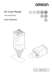


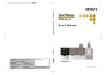


![[Insert the picture here]](http://vs1.manualzilla.com/store/data/005750886_1-61b7896b0a61bec1f004b64a994fc9d3-150x150.png)