1
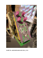
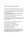
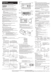
SNAZZY FX ARDCORE INPUTS AND OUTPUTS: 1. A0 0-5 VOLTS : used in most sketches as a pitch or level control 2. A1 0-5 VOLTS: used in most sketches as a pitch or level control 3. A2 0-5 VOLTS : with no input plugged in/OR ATTENUATOR FOR (5. )WHEN CABLE PLUGGED IN 4. A3 0-5 VOLTS: with no cable plugged in/OR ATTENUATOR for (7.) WHEN CABLE PLUGGED IN 5. A2 JACK: CV IN 1 (turn knob A2 all the way up for full level) used as an audio input in some sketches 6. CLOCK: plug in a clock source here for sketches that need a clock. If you want to write a program that uses an external interrupt, you would use this input. 7. A3 JACK: CV IN 2 (turn knob A3 all the way up for full level) used as an audio input in some sketches 8. D0: Gate/Trigger Out (green LED lights on gate) 9. D1: Gate/Trigger Out (red LED lights on gate) 10. 8 bit DAC output JACK (jack one) 11. 8 bit DAC output JACK (jack two) 12. USB JACK (can be used for two way serial communication between ARDUINO software and the ARDCORE) use this to load sketches from the Arduino Software. If this is working, the “data leds” will light up briefly when a program transfers.