1
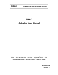
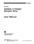
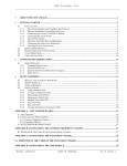
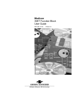
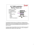
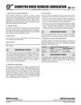
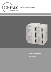
MOTORS - AC INDUCTION, SINGLE & POLYPHASE DRIVESYSTEMS RETAIN FOR FUTURE USE U30000 - 1 of 17 1. Overview 2. Motor Types This user manual applies to NORD Motor products and it provides general information for motor operation, installation, maintenance, inspection, repair, and trouble shooting, which is relevant to most of the motor products shipped by NORD. Information and instructions provided in this manual, safety and commissioning information and all other manuals applicable to any items supplied by NORD must be observed. NORD AC electric induction motors described in this manual generally include the following types: This instruction manual is not intended to include comprehensive details and information related to all possible design variations or accessories options available with NORD motors. If there is any uncertainty about specific procedures, instructions or motor details, then please refer these questions to NORD for additional information or clarification. Totally enclosed fan cooled (TEFC). Before installing, operating, or performing maintenance on any electrical motor become familiar with the following: • The detailed operating instructions and wiring diagrams. The TENV motor designs rely purely on convection cooling and they have no fan. Often TENV designs are labeled for intermittent or periodic duty or at a lower power rating than is typical for the given motor frame size. • All applicable national, local and system-specific regulations, codes and practices. Totally enclosed, blower cooled (TEBC) • The national / regional regulations governing safety and accident prevention. • The proper use of any tools, transportation or hoisting equipment, and safety equipment needed to complete the installation. • To avoid serious injury or possible damage to the equipment or machine, compliance with all safety and information notes is mandatory! WARNING All work involved in the transport, connection, commissioning and maintenance of any NORD product must be carried out by qualified and responsible technicians. All applicable national, regional, and local work regulations and safety requirements must also be complied with. NORD assumes no liability for personal injury, accidental death, or equipment damage and malfunctions resulting from failure to comply with installation or operating instructions, safety notes, or any work regulations and laws! WARNING To avoid electrocution, injury or death, make certain the motor is properly grounded, completely de-energized and brought to a no-voltage condition prior to working on any electrical connections. • Single speed or two-speed design. • Three phase alternating current or single phase design. • Enclosure types: TEFC, TENV, and TEBC. 3. Enclosure Types TEFC motor designs rely on fan that is mounted on the motor’s rotor shaft so the cooling capacity can vary based upon the motor’s operating speed. Totally enclosed, non-ventilated (TENV) The TEBC design uses separate blower or ventilator fan, with its own low wattage motor and a separate power supply, to provide continuous airflow and cooling. The blower can be used to extend the speed range of the motor and allow extreme slow speed operation without causing a concern for overheating. Blower data is provided in Table 6, page 11. 4. Voltage and Frequency Variation Voltage and frequency variations are based upon the assumption that the nameplate horsepower will not be exceeded and that the motor temperature may increase. Standard allowable deviations are based upon the type of motor labeling. NEMA and CSA Labeled Motors Variations are based upon the nominal utilization voltage, and not the service (supply) voltage as per ANSI C84.1. Service Voltages Utilization Voltages 120V, 208V, 240V, 480V, 600V 115V, 200V, 230V, 460V, 575V • Voltage variation at rated frequency = ±10%. • Frequency variations at rated voltage = ±5%. • Combined voltage/frequency variation = ±5%. CE Labeled Motors Per IEC 60038, allowable service voltage variations on in the current system, compared to the previous system, are as indicated. Previous Service Voltages 220V, 380V, 660V 240V, 415V Current Service Voltages 230V, 400V, 690V +6/-10% 230V, 400V +10/-6% • Per EN 60034-1 a ±5% voltage variation and a ±2% frequency variation can be tolerated. • The allowed variations are based upon the voltage (or voltage range) indicated on the motor nameplate. NORD Gear Limited Toll Free in Canada: 800.668.4378 06.13.12 NORD Gear Corporation Toll Free in the United States: 888.314.6673 www.nord.com/docs MOTORS - AC INDUCTION, SINGLE & POLYPHASE DRIVESYSTEMS RETAIN FOR FUTURE USE U30000 - 2 of 17 5. Motor Nameplate Information The motor nameplate and the display of technical information may vary slightly depending upon the global standard/s that the motor conforms to and the efficiency level. Please reference the examples below. www.nord.com C E 191510 US LR 112560 Mtr No. NEMA PH SF INS EFF DUTY IP FR % PF AMB ° rpm CENCL Hp Hz DP CODE kW rpm V Hz V A A Nm Brake VAC www.nord.com C E 191510 VDC US LR 112560 Mtr No. PH SF INS EFF DUTY NEMA IP FR % PF ENCL Hp Hz °C AMB rpm DP CODE kW rpm Hz V V A A VAC VDC 0850203-0 Nm Brake Type SK ~ Th Mot Cl F Nr IP S EN 60034 (H) V A kW COS 1/min φ MB= Hz Nm, AC V ~ ,DC V= Table 1. Nameplate Data Field Definition Field Definition Model / Type Power Factor Number of Phases Motor Frame Size Order Number Full Load Speed (rpm or 1/min ) Serial Number Efficiency Insulation Class NEMA Code Letter IP (Ingress Protection) Enclosure Rating Service Factor Duty Cycle Current Rating (If Service Factor ≥ 1.15) Ambient Temperature Rating (°C) Operating Voltage Rage (A) Enclosure Type Current Rating at Operating Voltage Range (A) Motor Frequency (Hz) Service Factor at Operating Voltage Range (A) Voltage Rating (V) Brake Rating (Nm) Current Rating (A) Brake Supply Voltage (VAC) Rated Power (HP or kW) Brake Coil Voltage (VDC) NORD Gear Limited Toll Free in Canada: 800.668.4378 06.13.12 2 NORD Gear Corporation Toll Free in the United States: 888.314.6673 www.nord.com/docs MOTORS - AC INDUCTION, SINGLE & POLYPHASE DRIVESYSTEMS RETAIN FOR FUTURE USE U30000 - 3 of 17 6. Motor Options And Nomenclature NORD offers many options for its motors. The option code will be shown in the motor nomenclature. Below are commonly used options. Code AICM BRE EAR ECR EHB EP F FC FHL H HL IG IP66 IR KB KD MIK MS Description Additional Internal Insulation Coating Applied With Brake Single Phase, Start Cap/Run Cap Single Phase, Start Cap/Run Cap Increased SF Single Phase, Run Capacitor Only Epoxy Dipped Windings Blower Cooling Fan - 3ph & 1ph Blower Cooling Fan - 1ph Brake – Lockable Manual Release Energy Efficient Brake – Manual Hand Release Incremental Encoder IP66 Environmental Protection Brake – Current Sensing Relay Condensation Holes - Removable Plugs Condensation Holes - Open Brake – Microswitch Power Plug Connector Code OL OL/H P RD RDD RG RLS SH SR TF TW VN VR VW VZ-F WE WU Z Description TENV Motor – Without Fan / With Cover TENV Motor - Without Fan & Cover Premium Efficient Motors Canopy Cover Double Canopy Cover Brake – Corrosion Protected Backstop Motor Space Heater Brake – Dust Protected Thermistor Thermostat 10:1 Constant Torque Rated Motor 5:1 Constant Torque Rated Motor 20:1 Constant Torque Rated Motor 1000+:1 Constant Torque Rated Motor 2nd Motor Shaft End High Slip Rotor High Inertia Motor Fan Motor Nomenclature 100L / 4 BRE 40 ... Other Options Brake Size Nm Brake Number of Poles Frame Size Ordering Examples 100L 4 BRE 100 HL 160L 2 BRE 40 FHL SR RG Corrosion Protection Dust & Corrosion Prot. Hand Release Lever Locking Hand Release Lever 100 Nm Brake Torque Brake 4 Poles Motor Frame Size 100 Frame Motor with 4 poles, Brake, 100 Nm with a hand release lever, corrosion protected brake, and a current sensing relay. NORD Gear Limited Toll Free in Canada: 800.668.4378 06.13.12 40 Nm Brake Torque Brake 2 Poles Motor Frame Size 63 Frame Energy efficient motor with 4 poles, Brake, 40 Nm with a locking hand release lever and dust & corrosion protection. NORD Gear Corporation Toll Free in the United States: 888.314.6673 www.nord.com/docs MOTORS - AC INDUCTION, SINGLE & POLYPHASE DRIVESYSTEMS RETAIN FOR FUTURE USE U30000 - 4 of 17 7. Application Conditions 8. Transportation Standard NORD motors are designed to operate in dusty or moist environments and have anti-fungal, thermal class F insulation. During transportation observe the following: • Enclosure Protection Rating = IP55 (minimum). • Maximum Installation Height = 3300 ft (1000 m). • Use all the lifting eyes that are intentionally supplied with the motor. • Ambient Temperature = -4 to 104°F (-20 to 40 °C). • Lift only at designed points. • Tropical-proof, Thermal Class F insulation. • Protect the mounting surface from possible damage during transportation. The protection level and maximum ambient temperature are stated on the motor nameplate. IMPORTANT NOTE NORD can provide motors for an expanded range of applications and service conditions including higher protection levels, extreme ambient conditions and, higher altitudes. WARNING Consult NORD for recommendations if motors are operated under extreme loading conditions, exposed to high inertia loads, or need to operate under unusually high cycling conditions with high starting and stopping frequency. • Make sure that all eyebolts and lifting lugs are tight and firmly against their supporting surface. • Always use sufficiently rated handling equipment, lift mechanisms and lifting straps. • With heavier objects or unbalanced loads, it may be appropriate to use more than one lifting point or an additional strap or sling to assure safe transportation of the assembly. This is especially true of assembled gearmotors and motorized reducers. • Once the NORD motor or assembly is properly installed, remove the transportation fixtures completely or make certain they are properly re-secured and tightened. WARNING Transportation – Use of Lifting Devices To avoid death, serious injury or equipment damage… WARNING • Hoisting lugs or lifting eyes attached to the motor are designed for the weight of the motor only! Do not attach any additional loads! Special design and assembly considerations are needed if NORD motors are subject to any of the following conditions: • The motor must only be transported and lifted using the lifting eyes, in a position that is appropriate for its type of construction. Otherwise, it could fall over or slip in the lifting tackle. • Outdoor installation with motor in a vertical position. • Direct contact with aggressive or corrosive materials (acids, bases, salts, certain gases, etc.). • Exposure to extreme high or low temperatures, high relative humidity, condensation moisture or very wet environments. • During suspended transport, two straps must be able to carry the entire load weight safely. • When required use additional, suitable means of support for transportation, installation or removal. • Always secure the support equipment to prevent it from slipping. • Subject to extreme material build-up on the unit (dirt, dust, sand, etc.). • Hazardous Locations (risk of fire or explosion). NORD Gear Limited Toll Free in Canada: 800.668.4378 06.13.12 NORD Gear Corporation Toll Free in the United States: 888.314.6673 www.nord.com/docs MOTORS - AC INDUCTION, SINGLE & POLYPHASE DRIVESYSTEMS RETAIN FOR FUTURE USE U30000 - 5 of 17 9. Storage 10. Safety Considerations If the motor is not in service, store it according to the following conditions: When installing, servicing or replacing electric motors it is important to be working in a “voltage-free” state. Observe the following safety rules. • Store the motor in a clean, dry, dirt-free, vibration free area. • Storage temperatures of 10°C (50°F) to 50°C (120°F) must be maintained. • Relative humidity must not exceed 60%. • If vibration in the area exceeds 0.002 inch (0.05 mm) at 60 hertz, then vibration isolation pads are suggested to prevent brinelling of the bearings. • Treat the unprotected shaft end and mating flange surfaces with a corrosion inhibitor that can be cleaned off prior to commissioning. • Before placing the motor into service, visually inspect the motor exterior for evidence of deterioration during storage. Turn the motor shaft by hand to make sure the shaft turns freely. • Motor space heaters, when provided, are to be connected and energized whenever there is a possibility that the storage ambient conditions will reach the dew point. Space heaters are optional. Remove motor from the storage container when the heater is energized. • If the motor needs to be stored for extended periods, or if it is stored in less than favorable conditions, it is recommend that the winding insulation resistance be checked prior to commissioning (page 7). • Even if stored in favorable conditions, the antifriction motor bearings and motor shaft seals may need to be replaced if the storage period is more than 4 years. Five Safety Rules 1. Disconnect the system. Disconnect the auxiliary circuits (brakes, space heaters, etc.). 2. Prevent reconnection (follow safe lock-out/tag-out practices). 3. Make sure that the equipment is at zero voltage. 4. Make certain the equipment is properly grounded and short-circuited. 5. Cover or isolate nearby components that are still electrically live. To energize the system, apply the measures in reverse order. Qualified Personnel All work involved in the transport, connection, commissioning and maintenance of any NORD product must be carried out by qualified and responsible technicians. For the purpose of this documentation, a qualified personnel is taken to mean a person or people who fulfill the following requirements: • Through appropriate training and experience, they are able to recognize and avoid risks and potential dangers in their particular field of activity. • They have been instructed to carry out work on the machine by the appropriate person responsible. • They are responsible for knowing and complying with all applicable national, regional, and local work regulations and safety requirements. NORD Gear Limited Toll Free in Canada: 800.668.4378 06.13.12 NORD Gear Corporation Toll Free in the United States: 888.314.6673 www.nord.com/docs MOTORS - AC INDUCTION, SINGLE & POLYPHASE DRIVESYSTEMS RETAIN FOR FUTURE USE U30000 - 6 of 17 10. Safety Considerations Ctd. General Warnings and Cautions WARNING To avoid electrocution, injury or death, make certain all electrical devices (motors, brakes, variable frequency drives, etc.) are properly grounded, completely de-energized, and brought to a no-voltage condition prior to working on any electrical connections. Remember that most of these devices carry potentially dangerous energy levels for a period of time after power is removed. Always follow proper lock-out/tag-out procedures. WARNING Electrical machines contain dangerous voltage levels, electrically live parts, rotating surfaces and hot surfaces. To prevent injury, death or possible equipment damage always observe the following: • Keep all safety covers and guards in place during operation. Remove and replace covers in compliance with the applicable safety regulations. • Allow the machine to cool down before starting any work on it. WARNING Maintain Proper Cooling Operating the motor without the intended cooling fan may cause overheating and result in very hot surfaces, personal injury and material damage. Never commission a motor intended to be fan cooled when it is missing the shaft-driven fan or external blower assembly. WARNING Condensation Drain Holes (Optional) Inserting objects into the condensation drain holes can damage the winding and can result in death, serious injury and damage to property! • Before opening sealed drain holes, make sure the motor is in a no-voltage condition. Close the condensation drain holes before re-commissioning. • Exercise caution around drain holes that are intended to be left open, especially when the motor is energized. • Operate the machines properly. • Perform regular maintenance on the machine. • Secure and guard free-standing shaft extensions. WARNING Electrically Live Parts Electrical machines contain electrically live parts. Fatal or severe injuries and substantial material damage can occur if the required covers are removed or if the machines are not handled, operated, or maintained properly. STOP HARMFUL SITUATION STOP Before start-up check the following: • All electrical connections are secure, well grounded and properly made. • The motor is rotating in the correct direction (when de-coupled from the driven load). • There are no temperature-sensitive parts (cables etc.), in contact with motor enclosure. • Condensation drain holes are always located at the lowest point of the motor. WARNING Rotating Parts Electrical machines contain dangerous rotating parts. Fatal or severe injuries and substantial material damage can occur if the required covers are removed or if the machines are not handled, operated, or maintained properly. WARNING Hot Surfaces Electrical machines have hot surfaces. Fatal or severe injuries and substantial material damage can occur if the required covers are removed or if the machines are not handled, operated, or maintained properly. Allow the machine to cool down before starting any work on it. NORD Gear Limited Toll Free in Canada: 800.668.4378 06.13.12 NORD Gear Corporation Toll Free in the United States: 888.314.6673 www.nord.com/docs MOTORS - AC INDUCTION, SINGLE & POLYPHASE DRIVESYSTEMS RETAIN FOR FUTURE USE U30000 - 7 of 17 11. Checking the Insulation Before putting the motor into operation for the first time, after a lengthy period of storage or standstill (approx. 6 months), the insulation resistance of the winding should be checked. WARNING During and directly after measurement the motor connection terminals carry hazardous voltages. A. Control Typical motor bearing grease is an NLGI No. 2 consistency, high grade product with a polyurea base thickener, synthetic or blended mineral/synthetic oil, and stabilizing agents to protect against heat and oxidation. Table 3 – Motor Bearing Maintence Guidelines Frame Size 63-225 250 to 280 The insulation resistance of new, cleaned, or repaired motor windings against the grounded housing and against one another should be > 200 Mega-Ohms. B. Measurement Using a Mega-Ohm meter apply a DC voltage of 500 VDC to the motor winding for a period of 60 seconds and record the winding insulation resistance compared to ground. • The 500 VDC test voltage is applicable to low voltage motors up to 1000 VAC. • When performing this test the temperature of the windings should be 25°C ± 15°C (77°F ± 27°F). C. Verification • If the insulation resistance of the winding is less than 50 Mega-Ohms, the cause may be moisture. The windings should be dried and the test should be repeated. • After any lengthy period of operation the insulation resistance may drop. So long as the measured value does not fall below the critical value of 50 Mega-Ohm, the motor may continue to be operated. • If the measured value falls below the critical 50 Mega-Ohm level, the cause must be established and the windings or winding sections must be cleaned, dried, repaired, or replaced as needed. 315 STOP Power Poles Re-greasing Interval 0.16-60 HP (0.12-45 kW) All Maintence Free 2 4000 h 75-125 HP (55-75 kW) 150-250 HP (132-200 kW) 4 to 8 8000 h 2 3000 h 4 to 8 6000 h HARMFUL SITUATION STOP When re-greasing motor bearings do not to mix different greases without verifying the compatibility with a reputable grease lubrication supplier. Mixing incompatible products can lead to bearing failure. 13. Mechanical Installation Integral motors, NEMA C-face motors, and IEC flange mounted motors must be rigidly secured to their mating connection surface using all fastening screws tightened to the proper bolt torque. It is good practice to apply a medium strength thread- locking agent (Loctite® 242) to the mounting screws. Foot mounted motors must be securely installed to a rigid and level foundation or mounting surface to minimize vibration and maintain alignment between the motor and shaft load. All mounting hole locations must be utilized. Tighten all hold down screws or bolts to the proper bolt torque. STOP HARMFUL SITUATION STOP Failure to provide a proper mounting surface may cause vibration, misalignment and bearing damage. 12. Bearing Lubrication NORD motor frame sizes 63 up to and including 225 are normally supplied with internally grease lubricated bearings and require no lubrication during normal operation. NORD motor frame sizes 250 and larger are supplied with grease fittings for re-greasing the motor bearings. IMPORTANT NOTE Motors with grease fittings are normally supplied with a label indicating the grease type used, the suggested relubrication interval, and the amount of new grease to be applied. General bearing maintence guidelines are listed in Table 3. Accurate alignment and proper balancing of output devices (couplings, belts, pulleys, etc.) is required to assure quite, low vibration, trouble free operation. When the motor is directly coupled to a gear drive or a driven machine make sure that the motor shaft and driven machine shaft are aligned with one another axially. STOP HARMFUL SITUATION STOP Inaccurate alignment may lead to bearing damage, excessive vibrations and shaft breakage. IMPORTANT NOTE For motor replacement guidelines see section 20 on page 15 and section 21 on page 16. NORD Gear Limited Toll Free in Canada: 800.668.4378 06.13.12 NORD Gear Corporation Toll Free in the United States: 888.314.6673 www.nord.com/docs MOTORS - AC INDUCTION, SINGLE & POLYPHASE DRIVESYSTEMS RETAIN FOR FUTURE USE U30000 - 8 of 17 14. Electrical Connections WARNING To avoid electrocution, injury or death, make certain all electrical devices (motors, brakes, variable frequency drives, etc.) are properly grounded, completely de-energized, and brought to a no-voltage condition prior to working on any electrical connections. Remember that most of these devices potentially dangerous energy levels for a period of time after power is removed. Always follow proper lock-out/tag-out procedures. IMPORTANT NOTE External motor brakes have their own connection requirements as indicated in the appropriate brake instruction manuals. WARNING If the motor has an integral brake, make certain there is no load connected to the driven equipment before releasing the brake. Otherwise serious injury, death, or damage to the equipment may result. • The supply voltage and frequency must agree with the motor nameplate data. • Always feed the connecting leads into the terminal box using appropriate mating cable glands. The mating connection cables and cable glands should be suitable for temperatures ≥ 194°F (90°C). • Tighten the terminal board screw connections on the on the main terminal board per the table below. Table 4 – Tightening Torque: Terminal Board and Grounding Screws Thread Size Nut Size Tightening Torque [mm] [lb-ft] [N-m] M4 7 0.6-0.9 0.8-1.2 M5 8 1.3-1.8 1.8-2.5 M6 10 2.0-3.0 2.7-4 M8 13 4.0-5.9 5.5-8 M10 17 6.6-9.6 9-13 M12 19 11.8-14.8 16-20 • Upon final assembly, the terminal box cover must be sealed so that it is dust-tight and water-tight. Thread Size M4 M5 M6 M8 Table 5 – Tightening Torque: Terminal Box Cover Screws Tightening Torque [lb-ft] [N-m] 0.6-0.9 0.8-1.2 0.9-1.3 1.2-1.8 1.1-1.8 1.5-2.5 2.2-3.7 3.0-5.0 • Provide the ends of the connecting leads and ground lead with cable lugs or curved ring eyelets before connecting them to the terminal board. • Make certain that the wiring connections and arrangement of the terminal board jumpers conform to the appropriate wiring diagram as provided in the motor terminal box and/or page 9 of this manual. NORD Gear Limited Toll Free in Canada: 800.668.4378 06.13.12 NORD Gear Corporation Toll Free in the United States: 888.314.6673 www.nord.com/docs MOTORS - AC INDUCTION, SINGLE & POLYPHASE DRIVESYSTEMS RETAIN FOR FUTURE USE U30000 - 9 of 17 15. Wiring Diagrams Frames 63-132 230 / 460V, 60Hz, 3Ø 200 / 400V, 50Hz, 3Ø 190 / 380V, 60Hz, 3Ø Frames 160 + 230 / 460V, 60Hz, 3Ø 200 / 400V, 50Hz, 3Ø 190 / 380V, 60Hz, 3Ø Frames 160 + 230 / 460V, 60Hz, 3Ø 200 / 400V, 50Hz, 3Ø 190 / 380V, 60Hz, 3Ø 120094410 T6 Y T5 L2 V1 T2 U1 T1 W1 T3 L1 T7 T1 L1 T8 T2 L2 T9 T3 L3 high voltage L2 L1 L3 T2 (V1) L3 T1 (U1) T3 (W1) V2 T5 V5 T8 U2 T4 U5 T7 T7 (U3) T4 (U2) W2 T6 W5 T9 T9 (W3) T6 (W2) T8 (V3) T5 (V2) Y high voltage T4 WIRING DIAGRAM 3 PHASE MOTOR WIRING DIAGRAM 3 PHASE MOTOR Y WIRING DIAGRAM 3 PHASE MOTOR High Voltage L2 T6 V1 T2 U1 T1 T8 T9 T1 T2 T3 L1 L2 W1 T3 L1 YY T7 YY T5 L3 L3 T2 (V1) T3 (W1) V2 T5 V5 T8 T8 (V3) T5 (V2) U2 T4 U5 T7 T7 (U3) T4 (U2) W2 T6 W5 T9 T9 (W3) T6 (W2) *JUMPER WIRES NEEDED T4 2U Y T4 U2 T1 U1 high voltage L1 L1 L3 T5 2V T2 V1 HIGH SPEED T1 1U T2 1V T3 1W T3 W1 T4 2U L3 T4 T5 U2 V2 T1 U1 T2 V1 T3 W1 L2 NORD Gear Limited T5 2V T6 2W LOW SPEED W2 L3 Toll Free in Canada: 800.668.4378 L1 T6 2W T5 V2 L2 T6 L2 T1 1U T2 1V T3 1W L1 L2 L3 Customer Supplied Starter Contacts 2 - SPEED MOTORS DUAL WINDING (8-2 POLE) T4 2U L2 L3 T5 2V T6 2W HIGH SPEED T1 1U T2 1V T3 1W T4 2U T5 2V T6 2W LOW SPEED T1 1U L1 T2 1V L2 T3 1W 2 - SPEED MOTORS DUAL WINDING L1 WIRING DIAGRAM 3 PHASE MOTOR T6 W2 2 - SPEED MOTORS SINGLE WINDING (4-2 & 8-4 POLE) 2 - SPEED MOTORS SINGLE WINDING 460 / 800V, 60Hz, 3Ø 230 / 400V, 50Hz, 3Ø 208 / 360V, 60Hz, 3Ø 400 / 690V, 50Hz, 3Ø 332 / 575V, 60Hz, 3Ø 06.13.12 T1 (U1) L2 L3 Low Voltage low voltage L1 low voltage YY low voltage T4 L3 NORD Gear Corporation Toll Free in the United States: 888.314.6673 www.nord.com/docs MOTORS - AC INDUCTION, SINGLE & POLYPHASE DRIVESYSTEMS RETAIN FOR FUTURE USE U30000 - 10 of 17 15. Wiring Diagrams Ctd. TERMINAL BLOCK FROM MOTOR TO CONTROL DEVICE * MAX. OPERATING VOLTAGE 2.5V. * SWITCH TEMP. 155°C * RESPONSE TIME < 5 SECONDS * NC (NORMALLY CLOSED) * CONTACTS RATED 1.6A AT 2.50 VAC * 6-500 VAC WORKING RANGE * AUTOMATIC RESET AT 30 ± 15°C TEMP. DROP TERMINAL BLOCK TO CONTROL DEVICE THERMISTATS “TW” OPTION OPTION “F” 1 PH 120095230 120095240 THERMISTOR “TF” OPTION FROM MOTOR OPTION “F” 3 PH 380-575V 50 / 60 Hz 1 PHASE 115V* 50/60 Hz 230V 50 / 60 Hz 220-332V 50 / 60 Hz * CAPACITOR IS SUPPLIED * CAPACITOR IS SUPPLIED BLOWER COOLING FAN “F” OPTION 120095250 FROM MOTOR 120095450 BLOWER COOLING FAN “FC” OPTION TERMINAL BLOCK TO CONTROL DEVICE NORD Gear Limited Toll Free in Canada: 800.668.4378 06.13.12 120095220 SPACE HEATER “SH” OPTION NORD Gear Corporation Toll Free in the United States: 888.314.6673 www.nord.com/docs MOTORS - AC INDUCTION, SINGLE & POLYPHASE DRIVESYSTEMS RETAIN FOR FUTURE USE U30000 - 11 of 17 16. Motor Accessories Blower Cooling Fan (Option F & FC) • Connection Diagram Shown on page 10 • Option FC is 1-phase, 115V • Option F has capability of 1 phase by connecting a supplied capacitor Option F – 3ph & 1ph 220-575V 50/60Hz 60Hz Ratings Motor Frame Voltage [V] 63 71 80 90 100 112 132 160 - 225 230 – 277 230 – 277 230 – 277 230 – 277 230 – 277 230 – 277 230 – 277 230 – 277 63 71 80 90 100 112 132 160 - 225 220 – 332 220 – 332 220 – 332 220 – 332 220 – 332 220 – 332 220 – 332 220 – 322 63 71 80 90 100 112 132 160 - 225 380 – 575 380 – 575 380 – 575 380 – 575 380 – 575 380 – 575 380 – 575 380 – 575 Current [A] 50Hz Ratings Power [W] Voltage [V] Single phase connection - (Delta) 0.11 38 230 – 277 0.12 41 230 – 277 0.13 44 230 – 277 0.25 88 230 – 277 0.28 88 230 – 277 0.31 107 230 – 277 0.27 89 230 – 277 0.41 140 230 – 277 Three phase low-voltage connection - (Delta) 0.08 23 220 – 290 0.08 24 220 – 290 0.08 25 220 – 290 0.21 64 220 – 290 0.21 66 220 – 290 0.23 70 220 – 290 0.25 74 220 – 290 0.49 165 220 – 290 Three phase high-voltage connection - (Y) 0.04 23 380 – 500 0.04 25 380 – 500 0.04 26 380 – 500 0.12 62 380 – 500 0.12 66 380 – 500 0.13 70 380 – 500 0.14 75 380 – 500 0.28 165 380 – 500 Current [A] Power [W] 0.10 0.10 0.11 0.26 0.26 0.26 0.29 0.45 27 28 29 72 70 73 82 128 0.10 0.10 0.01 0.28 0.27 0.27 0.32 0.52 27 30 29 86 86 85 96 155 0.05 0.05 0.05 0.16 0.16 0.16 0.18 0.29 29 30 29 82 83 82 96 155 Option FC – 115V 50/60Hz 1ph 60Hz Ratings Motor Frame Voltage [V] Current [A] 63 71 80 90 100 112 100 – 135 100 – 135 100 – 135 100 – 135 100 – 135 100 – 135 0.23 0.23 0.27 0.46 0.53 0.60 50Hz Ratings Power [W] Voltage [V] Single Phase Connection - (Delta) 42 100 – 135 47 100 – 135 57 100 – 135 102 100 – 135 105 100 – 135 115 100 – 135 Current [A] Power [W] 0.30 0.30 0.30 0.57 0.54 0.55 42 44 43 78 78 80 Table 6 – Option F & FC NORD Gear Limited Toll Free in Canada: 800.668.4378 06.13.12 NORD Gear Corporation Toll Free in the United States: 888.314.6673 www.nord.com/docs MOTORS - AC INDUCTION, SINGLE & POLYPHASE DRIVESYSTEMS RETAIN FOR FUTURE USE U30000 - 12 of 17 16. Motor Accessories Ctd. Thermostats (Option TW and Option 2TW) Standard connection Series connected, one per phase Contact NC (Normally Closed)/ Auto Re-setting Response Temperature (Option TW) 311 °F (155 °C) Shut-Off Device Response Temperature (Option 2TW) 311 °F (155 °C) Shut-Off Device + 266°F (130 °C) Alarm Device Nominal Current 1.6 Amp at 250 V Resistance < 50 mΩ Switch Rebound < 1ms Insulation Rating 2000 VAC Cycles 10,000 max Lead Identification (inside terminal box) P1 and P2 or TB1 and TB2 / 2TB1 and 2TB2 WARNING Thermostats and Thermistors will automatically reset. Motor thermostats or bi-metallic switches can be wired directly into the control circuit without a separate control module or tripping device. Thermostats operate on a relatively high control voltage so they are much less sensitive to voltage interference from the main power supply. Often one can run thermostat leads and motor power leads next to each other when using the appropriate shielded cable. The installer is responsible to wire the thermostats into the motor control circuit. The leads may be labeled in a variety of ways as indicated. WARNING All wiring must be completed by qualified personal and adhere to all local codes. Space Heaters (Option SH) • Connection Diagram shown on Page 9 • Space Heaters are mounted directly on the motor winding • The leads are brought into the terminal box and labeled H1 and H2 • They require a separate voltage supply and must not be energized when the motor is energized • The heaters will keep the winding of the motor approximately 5°C above the surrounding ambient Table 5. Space Heater Data Frame Size Wattage 63 & 71 18W 80 25W 90 – 112 50W 132-180 100W 200 & 225 120W Thermistors (Option TF) Standard Connection Three devices, series connected, one per phase Type Positive temperature coefficient (PTC) Transition Temperature 150°C±5 °C Resistance 20… 500Ω (below transition) > 4 kΩ (above transition) Reed Current < 1mA Max Voltage 30V Lead Identification (inside terminal box) P1 and P2 or TP1 and TP2 With a separate control module or tripping device (ex. Kirwan INT69) thermistors are used to sense motor overload/ over temperature conditions by converting the critical operating temperature limit into large internal resistance change. Due to their small size, heat sink construction, and high change in resistance value, minor resistance variations caused by relatively long lead runs can be tolerated. This feature also allows for one controller to be used for several temperature sensing locations. Many variable frequency drives come with on-board thermistor inputs. NORD does not supply the thermistor control module. NORD Gear Limited Toll Free in Canada: 800.668.4378 06.13.12 Voltages 110V 230V 460V 110V 230V 460V 110V 230V 460V 110V 230V 460V 110V 230V 460V Heater Strips/MTR 1 1 2 2 2 Encoder (Option IG) • • • • • • • • Most standard encoders will be enclosed inside the fan cover Incremental, Quadrature, Differential, Marker Channel IP66 Protection IG1 = 1024PPR, IG2 = 2048PPR, IG4 = 4096PPR TTL/RS422, HTL/Push-Pull, Line Driver. 5V or 10-30V available. Absolute encoders also available. Seperate encoder wiring instructions are provided by NORD. NORD Gear Corporation Toll Free in the United States: 888.314.6673 www.nord.com/docs MOTORS - AC INDUCTION, SINGLE & POLYPHASE DRIVESYSTEMS RETAIN FOR FUTURE USE U30000 - 13 of 17 17. Inspection Inspect the motor after every 500 operating hours. WARNING If it is necessary to clean the motor exterior, do not use shop air. Shop air can force contaminents into the motor and may cause parts damage or result in blowing debris causing injury. Table 8 - Inspection Guidelines Inspect Check Action Motor Exterior Check the external surfaces for contamination. Accumulation of dirt and fibrous deposits must be removed. Clean the motor external surfaces using clean, lint-free cloths. Clean deposits from between cooling fins using a vacuum cleaner and a stiff-bristled nylon brush. Check the external surfaces for oil film and greasy deposits. Clean the oil film and greasy deposits from the motor surface using clean, lint-free cloths. If necessary, moisten the cloth with an approved non-flammable, residue-free solvent. Do not pour solvent on the motor. Check for evidence of damage or overheating. If the motor has physical damage, replace the motor. Motor Mountings Make sure the mounting hardware is secure. If the mounting hardware is not secure, check the motor/gearbox alignment, and tighten the mounting hardware. Motor Electrical Connections Check that all electrical connections are secure. If the electrical connections are not secure, tighten them. Check the electrical connections for evidence of arcing. Loose electrical connections can cause arcing, which is evident by discoloration and charring. If you find evidence of arcing, replace the damaged connections. Insulation Resistance Using an ohmmeter, check and record the resistance of motor winding insulation. Compare the current resistance reading to previous readings. If the resistance drops significantly, perform an internal inspection for insulation damage or deterioration. Motor Brake On motors that have a brake, use a feeler gauge to check the If the air gap exceeds the maximum allowed for air gap in between the brake pad and the rotor according to that brake configuration provided in the manual, the appropriate user manual. adjust the air gap or replace the brake pad according to user manual U35000. NORD Gear Limited Toll Free in Canada: 800.668.4378 06.13.12 NORD Gear Corporation Toll Free in the United States: 888.314.6673 www.nord.com/docs MOTORS - AC INDUCTION, SINGLE & POLYPHASE DRIVESYSTEMS 18. RETAIN FOR FUTURE USE U30000 - 14 of 17 Parts List If you are ordering a part, provide the model and order number (table 1, page 2) of your motor. This will determine the specific part number you need. 932-1 947 900 932 940-1 929 948 900 918 916 923 952 902 902-1 905 906 923 TBLK-1 904 902-2 6 902-1 919 902 907 933 909 TBLK 921 940 910 907-1 939 908-1 920 960 961 908 902-1 902 Part Number 6 900 902 902-1 902-2 904 905 906 907 907-1 908 908-1 909 910 916 918 919 920 Part Description Qty per Assembly Input Pinion 1 Rotor Assembly 1 A-Endbell 1 Screw 4 Dubo Seal 4 Oil Seal 1 Bearing 1 Preload Spring 1 Terminal Box Frame 1 Screw 4 Terminal Box Cover 1 Screw 4 Gasket - Terminal Box Frame 1 Gasket - Terminal Box Cover 1 Stator 1 Key 1 Retaining Ring 1 Oil Plug 1 NORD Gear Limited Toll Free in Canada: 800.668.4378 06.13.12 Part Number 921 923 929 932 932-1 933 939 940 940-1 947 948 952 960 961 TBLK TBLK-1 Part Description Qty per Assembly Gasket 1 Screw 4 Bearing 1 B-Endbell 1 Screw 4 Oil Seal 1 Fan 1 Fan Cover 1 Screw 4 Retaining Ring 1 Retaining Ring 1 Fan Clip 1 NPT Thread Adapter 1 Plug (includes O-ring) 1 Terminal Block 1 Screw, Terminal Block Mounting 2 Jumper Bar (not illustrated) AR NORD Gear Corporation Toll Free in the United States: 888.314.6673 www.nord.com/docs MOTORS - AC INDUCTION, SINGLE & POLYPHASE DRIVESYSTEMS RETAIN FOR FUTURE USE U30000 - 15 of 17 19. Repair Reference the parts list drawing on page 14 for clarification. A. Disassemble the motor according to the general exploded view in PARTS INFORMATION. Disassemble only as far as necessary to replace the failed parts. B. Whenever the motor is disassembled, clean all dust and contamination from the motor interior using a vacuum cleaner and a soft-bristled nylon brush. C. The following parts must be replaced if they are removed: • Oil seal (904), Oil seal (933) • Gasket (909), Gasket (910), Gasket (921) • Gasket on plug (961) • Self-locking screws (907-1, 908-1, 923, 932-1, 940-1) • Dubo Seals (902-2) D. If the following parts are removed, inspect them, and replace them if they are deformed or damaged: • Retaining ring (919), Retaining ring (947), Retaining ring (948) • Fan clip (952) 20. Removing and Replacing Integral Motors Reference the parts list on Page 14 for clarification. A. Disconnect the power to the electric motor. Make certain the motor is properly grounded, de-energized and secured with a lock-out/tag-out device. B. Drain the oil from the mating gearbox, or rotate the motor/gearbox assembly so that the motor is up, to prevent oil from spilling from the gearbox when the motor is removed. C. Support the motor and prepare it for removal. Steady the motor and support it. For larger motors, use of mechanical lifting or support devices to may be appropriate. D. Remove the fastening screws that hold the motor to the reducer input. F. Remove and discard the old flange gasket. G. Clean the gasket faces on the motor and gearbox, making sure no cleaning debris enters the gearbox. H. Check the replacement motor to make sure the motor flange, motor shaft, and motor pinion are identical to the motor that was removed. I. Place a new gasket between the gearbox and new motor. J. Position the motor on the gearbox, making sure the input pinion meshes with the input gear. Rotate the motor as necessary to align the bolt holes and seat the motor flange. Make sure the gasket remains properly aligned and seated K. Apply a medium strength thread locking compound to the bolt threads. Install the bolts and tighten them to the appropriate torque. IMPORTANT NOTE If the motor/gearbox installation uses an input flange, first mount the input flange to the motor using the four mounting bolts and NEW DUBO sealing rings under the head of each fastening screw. Make sure the fastening screws are clean and apply new thread sealant if necessary. L. Check the gearbox oil level in accordance with the appropriate User Manual/s. If necessary fill or add oil to the gearbox. STOP HARMFUL SITUATION STOP Do not mix different types of oil! M. Re-establish the electrical connection to the motor. N. Observe the subsequent start-up closely to make certain the equipment is operating properly and there are no seal or gasket leaks. IMPORTANT NOTE Most integral motor installations have mounting bolts accessible from the motor exterior. If the bolts are not clearly visible, unbolt the input flange from the gearbox. Remove the bolts securing the motor to the reducer input flange, and discard the old DUBO sealing rings that were under the screw heads. E. Maintain motor shaft alignment and move the motor directly away from its mounting surface until the motor shaft and mating input gear clear both the internal gear mesh and reducer input. NORD Gear Limited Toll Free in Canada: 800.668.4378 06.13.12 NORD Gear Corporation Toll Free in the United States: 888.314.6673 www.nord.com/docs MOTORS - AC INDUCTION, SINGLE & POLYPHASE DRIVESYSTEMS RETAIN FOR FUTURE USE 21. Removing and Replacing NEMA C-Face or IEC Fange-Mounted Motors 22. Testing IMPORTANT NOTE For further clarification of these instructions, reference the parts list on Page 14 of this manual. A. Disconnect the power to the electric motor. Make certain the motor is properly grounded, de-energized and secured with a lock-out/tag-out device. B. Support the motor and prepare it for removal. Steady the motor and support it. For larger motors, use of mechanical lifting or support devices to may be appropriate. C. Remove the fastening screws that hold the motor to the C-face or IEC mounting flange. D. Maintain motor shaft alignment, and move the motor directly away from its mounting surface until the motor shaft and mating coupling clear the mounting flange surface of the driven equipment. U30000 - 16 of 17 NORD electric motors do not require periodic testing. However, if a motor is removed from its installation, NORD recommends that the motor be checked according to the following static and dynamic testing procedures before it is reinstalled. Finding a condition that will require future repair before the motor is reinstalled decreases the overall maintenance time. This section provides general test information and functional checks for the types of motors covered by this manual. Read and understand the tests and checks before performing them on your motor. Record and date all measurements taken. E. Measure and record the proper placement of the motor shaft coupling prior to removing it from the old motor. If the motor fails any of the test procedures provided below, use the troubleshooting guide to determine the motor problem. F. Make sure the new motor shaft, key and key slot are free of all nicks, burrs, and lubrication or grease. Static Testing G. Install the new shaft key on the new motor. If the shaft key is not captured or if an open-ended key slot is utilized it is good practice to secure the key into the key slot with a medium strength thread locking agent or alternatively one may stake the key in place. H. Re-install the coupling on the new motor shaft, making sure the placement of the coupling is in the same location as it was on the old motor (See Step E). I. Clean all old gasket material, sealants, contamination, and corrosion from the flange surface on the driven equipment. J. If the motor is utilized in a wet or wash down environment apply a sealing gasket or gasket eliminating compound to the mating flange surface, as would seem most appropriate for the application. K. Support the new motor and mount it flush against the mating flange surface of the driven equipment. L. Apply a medium strength thread locking agent to the bolt threads. M. Install the bolts and tighten them to the appropriate torque. N. Re-establish the electrical connection to the motor. O. Observe the subsequent start-up closely to make certain the equipment is operating properly. A. The motor can only be static tested if it is disconnected from the component it drives and securely mounted on a fixture or mounting plate. These tests are usually conducted when a motor has been removed for any reason other than failure B. Turn the motor shaft slowly by hand. Feel and listen for evidence of a failed bearing, which is indicated by a rough feel as the shaft rotates, and by noise. C. Check for smooth rotation, with no evidence of binding or catching. If the shaft does not rotate smoothly, or binds or catches, the bearings are worn or failing, lack lubrication, or are contaminated. D. Check the motor shaft for side play by applying pressure at right angles to the shaft in several places around the circumference. If the shaft moves perceptibly, the front bearing may be worn. Dynamic Testing A. Find the motor voltage and rated load current values as listed on the motor nameplate. B. Using a volt-ohmmeter, verify that the motor power supply is in the correct range. C. Run the motor with no load. As the motor is operating, listen for unusual motor noise and check for excessive vibration. Vibration and motor noise are indications of bearing contamination, lack of lubrication, damage, or failure. D. Use an ammeter to measure the no-load current. Record the no-load current for comparison with previous readings, and for reference during future testing. E. If the motor passes the no-load test, operate the motor at rated load and check and record the current. F. Check the motor operating temperature at rated load. If the motor operates at a higher than normal temperature, the motor may be damaged, overloaded or failing. NORD Gear Limited Toll Free in Canada: 800.668.4378 06.13.12 NORD Gear Corporation Toll Free in the United States: 888.314.6673 www.nord.com/docs MOTORS - AC INDUCTION, SINGLE & POLYPHASE DRIVESYSTEMS RETAIN FOR FUTURE USE U30000 - 17 of 17 23. Troubleshooting Fault Likely Cause Corrective Action Motor fails to start. • • • • Motor is mis-wired Brake is may not be releasing. Fan guard damaged and contacting fan. Motor protection device has tripped or does not switch • 1-Ph Capacitor or start switch has failed. • • • • Fuses blow or motor protection faults immediately. • • • • • • • • • Motor hums and has high current consumption • Brake may not be releasing. • Rotor may be rubbing stator. • Defective or incorrect stator winding. Short circuit in line. Lines connected incorrectly. Fuse or circuit breaker tripped. Motor is overloaded or equipment jammed. Stator is shorted or went to ground. Verify and correct motor wiring. Troubleshoot brake per User Manual U35000. Replace damaged fan guard. Check motor protection device for correct setting and correct error. • Discharge capacitor and use a volt-ohm meter to check the capacitor for an open circuit - replace if needed. Inspect switch and connections. Replace if contacts look burned or pitted. Rectify short circuit. Check circuit diagram and make corrections. Replace fuse or circuit breaker. Make sure load is free. Verify motor amp draw compared to nameplate rating. • A damaged or blown stator will show a burn mark. Stator must be repaired or replaced. • Troubleshoot brake per User Manual U35000. • Send motor to a repair specialist. Severe speed loss under load • Overload. or excessive acceleration time. • Excessive voltage drop. • Damaged or failing motor bearings. • Damaged or worn gear unit. • 1-Ph Capacitor or start switch has failed. • Check load conditions and make certain system is unobstructed. Reduce load or consider a larger motor. • Verify service voltage is within specification. Check if nearby equipment is affecting incoming power. Make sure connection harness and wiring is adequate. • Replace motor bearings. • Replace or repair damaged gear unit. • See instructions under “Motor fails to start”. Motor runs the incorrect direction. • Incorrect wiring. • Rewire motor according to system schematic and/or switch two incoming motor phases. Motor heats up excessively or thermal overload protection trips • • • • • • • Overload. Ambient temperature is too high. Inadequate cooling. Operation is outside the allowed duty cycle. Motor protection device may be defective. Excessive supply voltage. System short or damaged stator. • Make sure load is free. Verify motor amp draw compared to nameplate rating. Reduce load or consider a larger motor. • Do not operate above the rated conditions. • Correct cooling air supply. Open and clear cooling air passages. Retrofit with forced ventilator fan if needed. • Adjust operating duty cycle or contact a specialist to select a suitable motor or drive. • Replace motor protection device. • Adapt motor supply voltage. • Check for loose, cut or damaged wires. Check stator winding for defects or burn damage. Excessive Noise or Vibration • Motor bearings contaminated or damaged. • Excessive motor shaft end play. • Misaligned or imbalanced load. • Test motor by itself. If bearings are bad noise may be heard or roughness detected. Replace bearings. Add lubrication if bearings have grease fittings. • Check shaft endplay with motor and system power disconnected. If shaft movement is excessive replace motor shaft bearings. • Check all mating shaft connections for proper alignment and correct all imbalanced load conditions. 1 Ph Start Capacitor Failures • Motor is not coming up to speed quickly enough. • Verify motor size to load conditions. Motor • Motor is being cycled frequently should come up to speed in no more than 2-3 • Start switch is defective or damaged. seconds. • Verify duty cycle and consult specialist for recommendations. • Replace start switch. 1 Ph Run Capacitor Failures • Possible power surge to motor caused by transient voltage or lightening. • Excessive ambient temperature. NORD Gear Limited Toll Free in Canada: 800.668.4378 06.13.12 • Install proper surge protection. • Verify ambient conditions do not exceed nameplate value. NORD Gear Corporation Toll Free in the United States: 888.314.6673 www.nord.com/docs