1
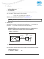
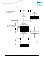
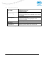
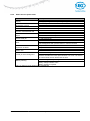
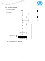
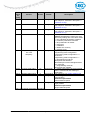
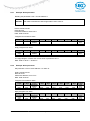
4.1.1.2 Inching mode Inching mode is enabled in the ‘positioning mode’ only. You can program via parameters acceleration as well as speed in the inching mode. NOTICE 4.1.1.2.1 There is no compensation for spindle backlash (loop positioning) in this operating mode! Inching mode 1 The drive travels once from the current actual position by the position ‘Delta Tipp’ depending on the mathematical sign of the value entered. ‘Delta Tipp‘ < 0: ‘Delta Tipp‘ > 0: negative travel direction positive travel direction If the ‘Spindle pitch’ parameter is programmed to zero, then the traveling way occurs by increments. If ‘Spindle pitch’ is unequal zero, then the information of the ‘Delta Tipp’ parameter refers to the travel distance in 1/100 mm. NOTICE Reaching of the target position will be signaled accordingly. The following conditions must be met for enabling the start of inching modes 1 and 2: The actuator must not be switched to error No active travel job Supply voltage of the output stage is applied NOTICE 4.1.1.2.2 If the actual position is outside the programmed limiting values, then traveling from this position in the respective direction is possible by means of inching mode 1 or 2! Inching mode 2 The actuator travels from the current actual position as long as the relevant command is active. You can influence the inching speed via two parameters and it will be calculated in the actuator as illustrated in the example below: v - Tipp (Parameter no. 9) = 10 rpm (can only be changed in the idle state) Offset inching 2 (Parameter no. 30) = 85 % (can be changed during inching operation) The resulting inching speed in this example will be: Inching speed = v - Tipp * Offset inching 2 = 10 rpm * 85 % = 9 rpm The results are always rounded to integers. The minimum speed is 1 rpm. AG03/1-RS485/SIKONETZ5 x Date: 31.03.2014 Page 8 of 36 Art.no. 86679 Mod. status 112/14