1
Introduction
Simulation Task Overview
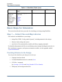
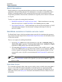
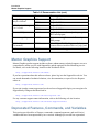
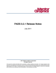
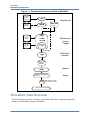
Figure 1-1. Operational Structure and Flow of ModelSim
VHDL
Design
Libraries
vlib
Vendor
vmap
Design
files
vlog/
vcom/
sccom
.ini or
.mpf file
Analyze/
Compile
Libraries
Map libraries
local work
library
HDL/SystemC
Analyze/
Compile
OPTIONAL:
Optimize
vopt
compiled
database
Simulate
vsim
Interactive Debugging
activities
Debug
Simulation Output
(for example, vcd)
Post-processing Debug
Simulation Task Overview
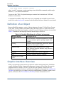
The following table provides a reference for the tasks required for compiling, optimizing,
loading, and simulating a design in ModelSim.
52
ModelSim SE User’s Manual, v10.3
Introduction
Simulation Task Overview
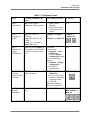
Table 1-1. Simulation Tasks
Task
Example Command Line
Entry
Step 1:
Map libraries
vlib <library_name>
vmap work <library_name>
Step 2:
Compile the
design
vlog file1.v file2.v ...
(Verilog)
vcom file1.vhd file2.vhd ...
(VHDL)
sccom <top> (SystemC)
sccom -link <top>
Step 3:
Optimize the
design
(OPTIONAL)
N/A
Optimized when voptflow = 1 To disable
optimizations:
in modelsim.ini file (default
1. Simulate > Start
setting for version 6.2 and
Simulation
later.
2. Deselect Enable
Optimization button
To set optimization
options:
1. Simulate > Design
Optimization
2. Set desired
optimizations
Step 4:
Load the
design into the
simulator
vsim <top> or
vsim <opt_name>
Simulate
1. Simulate > Start
Simulation
2. Click on top design
module or optimized
design unit name
3. Click OK
This action loads the
design for simulation.
Step 5:
Run the
simulation
run
step
Simulate > Run
ModelSim SE User’s Manual, v10.3
GUI Menu Pull-down
1. File > New >
Project
2. Enter library name
3. Add design files to
project
GUI Icons
N/A
Compile or
Compile > Compile
Compile All
or
Compile > Compile All
Run, or
Run continue, or
Run -all
53
Introduction
Basic Steps for Simulation
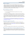
Table 1-1. Simulation Tasks (cont.)
Task
Example Command Line
Entry
GUI Menu Pull-down
GUI Icons
Step 6:
Debug the
design
Note: Design
optimization in
step 3 limits
debugging
visibility
Common debugging
commands:
bp
describe
drivers
examine
force
log
show
N/A
N/A
Basic Steps for Simulation
This section describes the basic procedure for simulating your design using ModelSim.
Step 1 — Collect Files and Map Libraries
Files needed to run ModelSim on your design:
•
•
•
design files (VHDL, Verilog, and/or SystemC), including stimulus for the design
libraries, both working and resource
modelsim.ini file (automatically created by the library mapping command)
For detailed information on the files accessed during system startup (including the modelsim.ini
file), initialization sequences, and system environment variables, see the Appendix entitled
“System Initialization”.
Providing Stimulus to the Design
You can provide stimulus to your design in several ways:
•
•
•
Language-based test bench
Tcl-based ModelSim interactive command, force
VCD files / commands
See Creating a VCD File and Using Extended VCD as Stimulus
•
54
Third-party test bench generation tools
ModelSim SE User’s Manual, v10.3
Introduction
Basic Steps for Simulation
What is a Library?
A library is a location on your file system where ModelSim stores data to be used for
simulation. ModelSim uses one or more libraries to manage the creation of data before it is
needed for use in simulation. A library also helps to streamline simulation invocation. Instead of
compiling all design data each time you simulate, ModelSim uses binary pre-compiled data
from its libraries. For example, if you make changes to a single Verilog module, ModelSim
recompiles only that module, rather than all modules in the design.
Work and Resource Libraries
You can use design libraries in two ways:
•
•
As a local working library that contains the compiled version of your design
As a resource library
The contents of your working library will change as you update your design and recompile. A
resource library is typically unchanging, and serves as a parts source for your design. Examples
of resource libraries are shared information within your group, vendor libraries, packages, or
previously compiled elements of your own working design. You can create your own resource
libraries, or they may be supplied by another design team or a third party (for example, a silicon
vendor).
For more information on resource libraries and working libraries, refer to Working Library
Versus Resource Libraries, Managing Library Contents, Working with Design Libraries, and
Specifying Resource Libraries.
Creating the Logical Library (vlib)
Before you can compile your source files, you must create a library in which to store the
compilation results. You can create the logical library using the GUI, by choosing File > New >
Library from the main menu (see Creating a Library), or you can use the vlib command. For
example, the following command:
vlib work
creates a library named work. By default, compilation results are stored in the work library.
Mapping the Logical Work to the Physical Work Directory (vmap)
VHDL uses logical library names that can be mapped to ModelSim library directories. If
libraries are not mapped properly, and you invoke your simulation, necessary components will
not be loaded and simulation will fail. Similarly, compilation can also depend on proper library
mapping.
ModelSim SE User’s Manual, v10.3
55
Introduction
Basic Steps for Simulation
By default, ModelSim can find libraries in your current directory (assuming they have the right
name), but for it to find libraries located elsewhere, you need to map a logical library name to
the pathname of the library.
You can use the GUI (Library Mappings with the GUI), a command (Library Mapping from the
Command Line), or a project (Getting Started with Projects) to assign a logical name to a design
library.
The format for command line entry is:
vmap <logical_name> <directory_pathname>
This command sets the mapping between a logical library name and a directory.
Use braces ({}) for cases where the path contains multiple items that need to be escaped, such as
spaces in the pathname or backslash characters. For example:
vmap celllib {$LIB_INSTALL_PATH/Documents And Settings/All/celllib}
Step 2 — Compile the Design
To compile a design, run one of the following ModelSim commands, depending on the
language used to create the design:
•
•
•
vlog — Verilog
vcom — VHDL
sccom — SystemC
Compiling Verilog (vlog)
The vlog command compiles Verilog modules in your design. You can compile Verilog files in
any order, since they are not order dependent. See Verilog Compilation for details.
Compiling VHDL (vcom)
The vcom command compiles VHDL design units. You must compile VHDL files in the order
necessitate to any design requirements. Projects may assist you in determining the compile
order: for more information, see Auto-Generating Compile Order. See Compilation and
Simulation of VHDL for details on VHDL compilation.
Compiling SystemC (sccom)
The sccom command compiles SystemC design units. Use this command only if you have
SystemC components in your design. See Compiling SystemC Files for details.
56
ModelSim SE User’s Manual, v10.3
Introduction
Basic Steps for Simulation
Step 3 — Load the Design for Simulation
Running the vsim Command on the Top Level of the Design
After you have compiled your design, it is ready for simulation. You can then run the vsim
command using the names of any top-level modules (many designs contain only one top-level
module). For example, if your top-level modules are named “testbench” and “globals,” then
invoke the simulator as follows:
vsim testbench globals
After the simulator loads the top-level modules, it iteratively loads the instantiated modules and
UDPs in the design hierarchy, linking the design together by connecting the ports and resolving
hierarchical references.
You can optionally optimize the design with vopt. For more information on optimization, see
Optimizing Designs with vopt.
Using Standard Delay Format Files
You can incorporate actual delay values to the simulation by applying standard delay format
(SDF) back-annotation files to the design. For more information on how SDF is used in the
design, see Specifying SDF Files for Simulation.
Step 4 — Simulate the Design
Once you have successfully loaded the design, simulation time is set to zero, and you must enter
a run command to begin simulation. For more information, see Verilog and SystemVerilog
Simulation, SystemC Simulation, and VHDL Simulation.
The basic commands you use to run simulation are:
•
•
•
•
•
add wave
bp
force
run
step
Step 5 — Debug the Design
The ModelSim GUI provides numerous commands, operations, and windows useful in
debugging your design. In addition, you can also use the command line to run the following
basic simulation commands for debugging:
ModelSim SE User’s Manual, v10.3
57
Introduction
Modes of Operation
•
•
•
•
•
•
•
•
describe
drivers
examine
force
log
checkpoint
restore
show
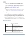
Modes of Operation
Many users run ModelSim interactively with the graphical user interface (GUI)—using the
mouse to perform actions from the main menu or in dialog boxes. However, there are really
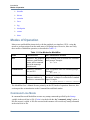
three modes of ModelSim operation, as described in Table 1-2.
Table 1-2. Use Modes for ModelSim
Mode
Characteristics
How ModelSim is invoked
GUI
interactive; has graphical from a desktop icon or from the OS command
windows, push-buttons, shell prompt. Example:
OS> vsim
menus, and a command
line in the transcript.
Default mode
Command-line
interactive command
line; no GUI
with -c argument at the OS command prompt.
Example:
OS> vsim -c
Batch
at OS command shell prompt using "here
non-interactive batch
document" technique or redirection of standard
script; no windows or
interactive command line input. Example:
C:\ vsim vfiles.v <infile >outfile
The ModelSim User’s Manual focuses primarily on the GUI mode of operation. However, this
section provides an introduction to the Command-line and Batch modes.
Command Line Mode
In command line mode ModelSim executes any startup command specified by the Startup
variable in the modelsim.ini file. If vsim is invoked with the -do "command_string" option, a
DO file (macro) is called. A DO file executed in this manner will override any startup command
in the modelsim.ini file.
58
ModelSim SE User’s Manual, v10.3
Introduction
Modes of Operation
During simulation a transcript file is created containing any messages to stdout. A transcript file
created in command line mode may be used as a DO file if you invoke the transcript on
command after the design loads (see the example below). The transcript on command writes all
of the commands you invoke to the transcript file.
For example, the following series of commands results in a transcript file that can be used for
command input if top is re-simulated (remove the quit -f command from the transcript file if
you want to remain in the simulator).
vsim -c top
library and design loading messages… then execute:
transcript on
force clk 1 50, 0 100 -repeat 100
run 500
run @5000
quit -f
Rename a transcript file that you intend to use as a DO file—if you do not rename it, ModelSim
will overwrite it the next time you run vsim. Also, simulator messages are already commented
out, but any messages generated from your design (and subsequently written to the transcript
file) will cause the simulator to pause. A transcript file that contains only valid simulator
commands will work fine; comment out anything else with a pound sign (#).
Refer to Creating a Transcript File for more information about creating, locating, and saving a
transcript file.
Stand-alone tools pick up project settings in command-line mode if you invoke them in the
project's root directory. If invoked outside the project directory, stand-alone tools pick up
project settings only if you set the MODELSIM environment variable to the path to the project
file (<Project_Root_Dir>/<Project_Name>.mpf).
Basic Command Line Editing and Navigation
While in command line mode you can use basic command line editing and navigation
techniques similar to other command line environments, such as:
•
History navigation — use the up and down arrows to select commands you have already
used.
•
Command line editing — use the left and right arrows to edit your current command
line.
•
Filename completion — use the Tab key to expand filenames.
ModelSim SE User’s Manual, v10.3
59
Introduction
Modes of Operation
Batch Simulation
Batch simulation is an operational mode that provides the user with the ability to perform
simulations without invoking the GUI. The simulations are executed via scripted files from a
Windows command prompt or UNIX terminal and do not provide for interaction with the
design during simulation. Data from the simulation run is typically sent to stdout or redirected
to a log file.
You have two options for running batch simulations:
1. BatchMode modelsim.ini Variable and vsim -batch — Batch simulations are run using
either the modelsim.ini variable BatchMode or the -batch argument to vsim.
2. Input Output Redirection — Batch simulations can also run from the Windows or UNIX
command prompt using the “here-document” technique redirecting I/O from one
process to another.
BatchMode modelsim.ini Variable and vsim -batch
The Batch Mode feature yields fast simulation times especially for simulations that generate a
large amount of textual output. Refer to Batch Mode Log Files and stdout for information about
saving transcript data.
There are two options for enabling Batch Mode:
1. Specifying vsim -batch with scripted simulations via the -do “<command_string>” |
<macro_file_name> argument. Combining vsim -batch with the -nostdout and -logfile
arguments to vsim yields the best simulation performance.
2. Uncommenting the BatchMode modelsim.ini variable. If this variable is set to 1, vsim
runs as if the -batch option were specified. If this variable is set to 0 (default), vsim runs
as if the -i option were specified. Transcript data is sent to stdout by default. You can
automatically create a log file by uncommenting the BatchTranscriptFile modelsim.ini
variable.
Note
You will receive an error message if you specify vsim -batch with the -c, -gui, or the -i
options. The BatchMode variable will be ignored if you specify the -batch, -c, -gui, or -i
options to vsim.
Batch Mode Scripts
The commands supported within a -do script are similar to those available when using vsim -c
however, none of the GUI-related commands or command options are supported by vsim
-batch. A command is available to help batch users access commands not available for use in
batch mode. Refer to the batch_mode command in the ModelSim Reference Manual for more
information.
60
ModelSim SE User’s Manual, v10.3
Introduction
Modes of Operation
You can use the CTRL-C keyboard interrupt to terminate batch simulation in UNIX and
Windows environments.
Batch Mode Log Files and stdout
The default behavior when using vsim -batch or BatchMode is to send transcript data to stdout
and not create a log file. You can save a log file in two ways:
•
•
Specify vsim -batch -logfile <file_name>.
Uncomment the BatchTranscriptFile modelsim.ini variable to automatically create a log
file. If BatchTranscriptFile is enabled, you can disable log file creation by specifying
vsim -nolog.
Table 1-3. vsim -batch Output Options
Operating Mode
Stdout
Logfile
vsim -batch or BatchMode = 1
Yes
No
vsim -batch -logfile <file_name>
Yes
Yes
vsim -batch -nostdout -logfile <file_name>
No
Yes
vsim -batch; BatchTranscriptFile = <file_name>
Yes
Yes
vsim -batch; TranscriptFile = <filename>
Yes
No
Input Output Redirection
In a Windows environment, you run vsim from a Windows command prompt. Standard input
and output are redirected to and from files. In a UNIX environment, you can invoke vsim in
batch mode by redirecting standard input using the “here-document” technique.
Note
By default, the here-document technique causes vsim to run in command (-c) mode. If
you want to run in batch mode, you need to specify vsim -batch or set BatchMode to 1 in
the modelsim.ini file.
The following is an example of the "here-document" technique. This example will open the
GUI in addition to running a batch simulation:
vsim top <<!
log -r *
run 100
do test.do
quit -f
!
Here is an example of a batch simulation using redirection of std input and output. In this
example, the -batch argument to vsim is included which prevents the GUI opening:
ModelSim SE User’s Manual, v10.3
61
Introduction
Definition of an Object
vsim -batch counter <yourfile >outfile
where “yourfile” represents a script containing various ModelSim commands, and the angle
brackets (< >) are redirection indicators.
You can use the CTRL-C keyboard interrupt to terminate batch simulation in UNIX and
Windows environments.
A command is available to help batch users access commands not available for use in batch
mode. Refer to the batch_mode command in the ModelSim Reference Manual for more details.
Definition of an Object
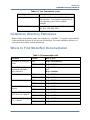
Because ModelSim supports a variety of design languages (SystemC, Unified Power Format
(UPF), PSL, Verilog, VHDL, and SystemVerilog), the word “object” is used to refer to any
valid design element in those languages, whenever a specific language reference is not needed.
Table 1-4 summarizes the language constructs that an object can refer to.
Table 1-4. Possible Definitions of an Object, by Language
Design Language
An object can be
VHDL
block statement, component instantiation, constant,
generate statement, generic, package, signal, alias,
variable
Verilog
function, module instantiation, named fork, named
begin, net, task, register, variable
SystemVerilog
In addition to those listed above for Verilog:
class, package, program, interface, array, directive,
property, sequence
SystemC
module, channel, port, variable, aggregate
PSL
property, sequence, directive, endpoint
Unified Power Format
(UPF)
Graphic Interface Overview
While your operating system interface provides the window-management frame, ModelSim
controls all internal window features including menus, buttons, and scroll bars. Because the
graphical interface is based on Tcl/TK, you also have the capability to build your own
simulation environment. Preference variables and configuration commands (see modelsim.ini
Variables for details) give you control over the use and placement of windows, menus, menu
options, and buttons. See Tcl and Macros (DO Files) for more information on Tcl.
62
ModelSim SE User’s Manual, v10.3
Introduction
Standards Supported
Standards Supported
Standards documents are sometimes informally referred to as the Language Reference Manual
(LRM). This standards listed here are the complete name of each manual. Elsewhere in this
manual the individual standards are referenced using the IEEE Std number.
The following standards are supported for the ModelSim products:
•
VHDL —
o
IEEE Std 1076-2008, IEEE Standard VHDL Language Reference Manual.
ModelSim supports the VHDL 2008 standard features with a few exceptions. For
detailed standard support information see the vhdl2008 technote available at
<install_dir>/docs/technotes/vhdl2008.note, or from the GUI menu pull-down Help
> Technotes > vhdl2008.
Potential migration issues and mixing use of VHDL 2008 with older VHDL code are
addressed in the vhdl2008migration technote.
o
IEEE Std 1164-1993, Standard Multivalue Logic System for VHDL Model
Interoperability
o
IEEE Std 1076.2-1996, Standard VHDL Mathematical Packages
Any design developed with ModelSim will be compatible with any other VHDL system
that is compliant with the 1076 specifications.
•
Verilog/SystemVerilog —
o
IEEE Std 1364-2005, IEEE Standard for Verilog Hardware Description Language
o
IEEE Std 1800-2012. IEEE Standard for SystemVerilog -- Unified Hardware
Design, Specification, and Verification Language
Both PLI (Programming Language Interface) and VCD (Value Change Dump) are
supported for ModelSim users.
•
•
SDF and VITAL —
o
SDF – IEEE Std 1497-2001, IEEE Standard for Standard Delay Format (SDF) for
the Electronic Design Process
o
VITAL 2000 – IEEE Std 1076.4-2000, IEEE Standard for VITAL ASIC Modeling
Specification
SystemC —
o
•
IEEE Std 1666-2005, SystemC Language Reference Manual
Unified Power Format (UPF) —
ModelSim SE User’s Manual, v10.3
63
Introduction
Assumptions
o
(UPF 1.0) The Accellera Unified Power Format (UPF) Standard Version 1.0 –
February 22, 2007
o
(UPF 2.0) IEEE Std 1801-2009 – Standard for Design and Verification of Low
Power Integrated Circuits – March 27, 2009
ModelSim supports most of the UPF 1.0 UPF 2.0 features. Support details are
summarized in the Power Aware Simulation User’s Manual.
•
PSL —
o
IEEE Std 1850-2005, IEEE Standard for Property Specific Language (PSL). For
exceptions, see the Verification with Assertions and Cover Directives chapter.
Assumptions
Using the ModelSim product and its documentation is based on the following assumptions:
•
•
You are familiar with how to use your operating system and its graphical interface.
•
You have worked through the appropriate lessons in the ModelSim Tutorial and are
familiar with the basic functionality of ModelSim. You can find the ModelSim Tutorial
by choosing Help from the main menu.
You have a working knowledge of the design languages. Although ModelSim is an
excellent application to use while learning HDL concepts and practices, this document is
not written to support that goal.
Text Conventions
Table 1-5 lists the text conventions used in this manual.
Table 1-5. Text Conventions
64
Text Type
Description
italic text
provides emphasis and sets off filenames,
pathnames, and design unit names
bold text
indicates commands, command options, menu
choices, package and library logical names, as
well as variables, dialog box selections, and
language keywords
monospace type
monospace type is used for program and
command examples
The right angle (>)
is used to connect menu choices when
traversing menus as in: File > Quit
ModelSim SE User’s Manual, v10.3
Introduction
Installation Directory Pathnames
Table 1-5. Text Conventions (cont.)
Text Type
Description
path separators
examples will show either UNIX or Windows
path separators - use separators appropriate for
your operating system when trying the
examples
UPPER CASE
denotes file types used by ModelSim (such as
DO, WLF, INI, MPF, PDF.)
Installation Directory Pathnames
When referring to installation paths, this manual uses “<installdir>” as a generic representation
of the installation directory for all versions of ModelSim. The actual installation directory on
your system may contain version information.
Where to Find ModelSim Documentation
Table 1-6. Documentation List
Document
Format
How to get it
Installation & Licensing
Guide
PDF
Help > PDF Bookcase
HTML and PDF
Help > InfoHub
Quick Guide
(command and feature
quick-reference)
PDF
Help > PDF Bookcase
and
Help > InfoHub
Tutorial
PDF
Help > PDF Bookcase
HTML and PDF
Help > InfoHub
PDF
Help > PDF Bookcase
HTML and PDF
Help > InfoHub
Command Reference
Manual
PDF
Help > PDF Bookcase
HTML and PDF
Help > InfoHub
Graphical User Interface
(GUI) Reference Manual
PDF
Help > PDF Bookcase
HTML and PDF
Help > InfoHub
Power Aware Simulation
User’s Manual
PDF
Help > PDF Bookcase
HTML and PDF
Help > InfoHub
User’s Manual
ModelSim SE User’s Manual, v10.3
65
Introduction
Mentor Graphics Support
Table 1-6. Documentation List (cont.)
Document
Format
How to get it
Foreign Language
Interface Manual
PDF
Help > PDF Bookcase
HTML
Help > InfoHub
OVL Checkers Manager
User’s Guide
PDF
Help > PDF Bookcase
HTML
Help > InfoHub
Command Help
ASCII
type help [command name] at the prompt in
the Transcript pane
Error message help
ASCII
type verror <msgNum> at the Transcript or
shell prompt
Tcl Man Pages
(Tcl manual)
HTML
select Help > Tcl Man Pages, or find
contents.htm in \modeltech\docs\tcl_help_html
Technotes
HTML
available from the support site
Mentor Graphics Support
Mentor Graphics product support includes software enhancements, technical support, access to
comprehensive online services with SupportNet, and the optional On-Site Mentoring service.
For details, refer to the following location on the Worldwide Web:
http://supportnet.mentor.com/about/
If you have questions about this software release, please log in to the SupportNet web site. You
can search thousands of technical solutions, view documentation, or open a Service Request
online at:
http://supportnet.mentor.com/
If your site is under current support and you do not have a SupportNet login, you can register for
SupportNet by filling out the short form at:
http://supportnet.mentor.com/user/register.cfm
For any customer support contact information, refer to the following web site location:
http://supportnet.mentor.com/contacts/supportcenters/
Deprecated Features, Commands, and Variables
This section provides tables of features, commands, command arguments, and modelsim.ini
variables that have been superseded by new versions. Although you can still use superseded
66
ModelSim SE User’s Manual, v10.3
Introduction
Deprecated Features, Commands, and Variables
features, commands, arguments, or variables, Mentor Graphics deprecates their usage—you
should use the corresponding new version whenever possible or convenient.
The following tables indicate the in which the item was superseded and a link to the new item
that replaces it, where applicable.
Table 1-7. Deprecated Features
Feature
Version
New Feature / Information
Source Window Language
Template
10.3
No longer available.
Table 1-9. Deprecated Command Arguments
Argument
Version
New Argument / Information
Table 1-10. Deprecated modelsim.ini Variables
Variable
Version
New Variable / Information
Table 1-11. Deprecated HDL Attributes
Variable
ModelSim SE User’s Manual, v10.3
Version Language New Variable / Information
67
Introduction
Deprecated Features, Commands, and Variables
68
ModelSim SE User’s Manual, v10.3