1
Technical Specification
Parking Revenue Control System (PRCS)
December 14th, 2009
1
Ronald Reagan National Airport
Technical Specification PRCS
Control Information
Document Location
File Name
Technical Specification Parking Revenue Control System (PRCS)
Change Control
Version Date
Author
Change Description
1.0
June 1, 2009
Booz Allen
Internal version
2.0
June 15, 2009
Booz Allen
Changed based on input from Authority
3.0
July 23, 2009
Booz Allen
Implemented comments from the
Authority, Subs and Booz Allen
4.0
July 31, 2009
Booz Allen
Implemented comments from workshop
5.0
November 9,
2009
Booz Allen
Updated Appendix
6.0
December 4,
2009
Booz Allen
Final comments added based on industry
review
2
Ronald Reagan National Airport
Technical Specification PRCS
TABLE OF CONTENTS
Section
Page
ABBREVIATIONS....................................................................................................................... 6
1. GENERAL SCOPE OF WORK .............................................................................................. 8
1.1
1.2
1.3
1.4
1.5
PROJECT OVERVIEW........................................................................................................... 8
ENVIRONMENTAL REQUIREMENTS............................................................................. 10
INTERFACES ......................................................................................................................... 11
CODE REQUIREMENTS AND STANDARDS................................................................... 11
COUNT DEFINITIONS ..................................................................................................... 12
2. PRCS EQUIPMENT ............................................................................................................... 12
2.1
2.2
2.3
2.4
2.5
2.6
ENTRY EQUIPMENT ........................................................................................................... 12
2.1.1 Entry Station .................................................................................................................. 12
2.1.2 Barriers........................................................................................................................... 16
2.1.3 Patron Processing ........................................................................................................... 17
2.1.4 Entry Lane Logic............................................................................................................ 18
EXIT EQUIPMENT................................................................................................................ 19
2.2.1 Exit Stations ................................................................................................................... 19
2.2.2 Barriers........................................................................................................................... 21
2.2.3 Vehicle Detection Exit ................................................................................................... 21
2.2.4 Patron Processing ........................................................................................................... 22
2.2.5 Cash Payment at Cashier................................................................................................ 24
2.2.6 Magnetic Strip Credit/Debit Card Payment ................................................................... 25
2.2.7 Contactless Credit/Debit Card Payment......................................................................... 25
2.2.8 Credit/Debit Card Exception Exit .................................................................................. 25
2.2.9 Exception Transactions .................................................................................................. 26
2.2.10 Receipt Printing.............................................................................................................. 30
CENTRAL DATA MANAGEMENT SYSTEM................................................................... 32
2.3.1 PRCS’ Integration with ERP.......................................................................................... 32
2.3.2 General Requirements.................................................................................................... 32
2.3.3 System Requirements..................................................................................................... 33
2.3.4 PRCS Network Management ......................................................................................... 34
2.3.5 Data Storage Capacity.................................................................................................... 34
2.3.6 System Performance....................................................................................................... 35
2.3.7 Maintainability Requirements ........................................................................................ 37
2.3.8 System Hardware ........................................................................................................... 37
2.3.9 Software Requirements .................................................................................................. 38
2.3.10 Central Data Management System Security................................................................... 38
2.3.11 Communications Infrastructure...................................................................................... 40
2.3.12 Reporting Requirements................................................................................................. 40
2.3.13 Auditing and Revenue Control Requirements ............................................................... 48
SPACE COUNT SYSTEM ..................................................................................................... 52
2.4.1 General Requirements.................................................................................................... 52
2.4.2 Software Requirements .................................................................................................. 53
2.4.3 Workstation Functions ................................................................................................... 53
2.4.4 Design Requirements ..................................................................................................... 54
2.4.5 Operational Procedures .................................................................................................. 54
2.4.6 Parking Space Count Signs ............................................................................................ 55
2.4.7 Parking SCS Provisions ................................................................................................. 56
LICENCE PLATE RECOGNITION AND INVENTORY REQUIREMENTS ............... 56
2.5.1 Cashier Terminal............................................................................................................ 56
LICENCE PLATE INVENTORY SYSTEM........................................................................ 60
3
Ronald Reagan National Airport
Technical Specification PRCS
2.7
2.8
2.9
2.10
2.6.1 General Requirements.................................................................................................... 61
2.6.2 Inventory Device Functional Requirements................................................................... 61
2.6.3 LPI Process .................................................................................................................... 62
LICENCE PLATE RECOGNITION .................................................................................... 63
2.7.1 LPR System Overview ................................................................................................... 63
2.7.2 LPR Subsystem General Layout .................................................................................... 63
2.7.3 Credit Card In / Credit Card Out LPR Integration ......................................................... 64
2.7.4 Unique Features and Requirements................................................................................ 65
2.7.5 LPR Subsystem Hardware ............................................................................................. 65
2.7.6 LPR Subsystem Software............................................................................................... 67
2.7.7 LPR Subsystem Testing ................................................................................................ 68
2.7.8 LPR Subsystem Performance Requirement .................................................................. 68
2.7.9 Technical Support Response Requirements .................................................................. 69
LPR OPTIONS ........................................................................................................................ 69
2.8.1 Longterm LPR Maintenance Agreement ....................................................................... 69
2.8.2 LPR Equipment Per Lane Unit Price ............................................................................. 69
2.8.3 LPR Audit System.......................................................................................................... 70
SPACE MANAGEMENT SYSTEM (OPTION) .................................................................. 70
SYSTEM CONFIGURATION............................................................................................... 71
3. PROJECT SUPPORT.............................................................................................................72
3.1
3.2
3.3
3.4
3.5
3.6
3.7
3.8
PROJECT MANAGEMENT ................................................................................................. 72
3.1.1 Project Management Scope............................................................................................ 72
3.1.2 Program Requirements................................................................................................... 72
3.1.3 Project Meetings............................................................................................................. 74
DESIGN REVIEW .................................................................................................................. 76
3.2.1 System Configuration Management (SCM)................................................................... 76
3.2.2 Design Review Process .................................................................................................. 77
3.2.3 Conceptual Design Review (CDR) ................................................................................ 78
3.2.4 Preliminary Design Review (PDR) ................................................................................ 78
3.2.5 Final Design Review (FDR)........................................................................................... 79
3.2.6 Drawing Requirements................................................................................................... 80
TESTING ................................................................................................................................. 80
3.3.1 Inspection and Testing Program..................................................................................... 80
TRAINING .............................................................................................................................. 84
3.4.1 Training Guidelines........................................................................................................ 85
WARRANTY ........................................................................................................................... 88
3.5.1 Warranty Coverage ........................................................................................................ 88
3.5.2 Warranty Period ............................................................................................................. 88
3.5.3 Remedial Work .............................................................................................................. 88
3.5.4 Warranty Conditions ...................................................................................................... 88
3.5.5 Negligence ..................................................................................................................... 89
3.5.6 Consummable Items....................................................................................................... 89
3.5.7 Fleet Defects................................................................................................................... 89
3.5.8 Warranty Personnel........................................................................................................ 89
3.5.9 Warranty Repair Agreement .......................................................................................... 90
QUALITY ASSURANCE (QA) AND QUALITY CONTROL (QC) ................................. 91
3.6.1 Contractor’s QA Program Plan ...................................................................................... 91
INSTALLATION .................................................................................................................... 91
3.7.1 Installation Phasing ........................................................................................................ 92
3.7.2 Office Layouts................................................................................................................ 92
3.7.3 Removal and Disposal of Existing Equipment .............................................................. 93
3.7.4 General Physical Requirements ..................................................................................... 93
DOCUMENTATION .............................................................................................................. 95
3.8.1 Manual Submissions ...................................................................................................... 97
3.8.2 Revisions ........................................................................................................................ 97
4
Ronald Reagan National Airport
Technical Specification PRCS
3.8.3 Content Requirements.................................................................................................... 97
4. SERVICES ............................................................................................................................. 100
4.1
4.2
4.3
TECHNICAL SUPPORT ..................................................................................................... 100
MAINTENANCE .................................................................................................................. 100
4.2.1 Maintenance Provider .................................................................................................. 102
4.2.2 Preventive Maintenance Schedule ............................................................................... 102
4.2.3 Response Time – Corrective/Repair Services during Warranty Period ....................... 103
4.2.4 Maintenance Log.......................................................................................................... 103
4.2.5 Spare Componenets and Parts Replenishment ............................................................. 104
4.2.6 Maintenance Agreement .............................................................................................. 105
4.2.7 Software Upgrades ....................................................................................................... 106
4.2.8 Maintenance Support Reporting................................................................................... 106
PRCS MAINTENANCE REPORTING............................................................................. 107
4.3.1 Maintenance Reporting Function ................................................................................. 107
4.3.2 Maintenance Plan ......................................................................................................... 108
TABLES
1-1
1-2
1-3
1-4
2-1
2-2
2-3
2-4
3-1
Summary of Airport Parking Spaces
Summary of Parking Lanes By Type
Environmental Conditions
LCD Minimum Requirements
LED Minimum Requirements
Patron Fee Indicator Minimum Specifications
System Performance Levels
Transactional Time Requirements for all Non-Human Related Factors
List of Training Courses and Participants
APPENDIX
A
B
C
D
E
F
G
H
Milestone Payments
Site Survey
Interface Specification
Message Sign Interface Document
Automated Vehicle Identification (AVI) Interface Document
Proposed High-Level Architecture Diagram
Contract Data Requirements List (CDRL)
Existing PRCS Network Infrastructure Diagram
5
Ronald Reagan National Airport
Technical Specification PRCS
ABBREVIATIONS
ADA
CDR
CDRL
CF
COTS
CPI
DTE
EIA
EMI
EML
ERP
FAT
FDR
GUI
IP
IRWS
ISF
ISO
LCD
LCIP
LED
LLRC
LLRU
LPI
LPN
LPR
MTBF
NEC
NMT
NTP
OSHA
OSI
PCI DSS
PDF
PDR
PRCS
RFI
QA
Americans With Disabilities Act
Conceptual Design Review
Contract Deliverable Requirements List
Confidence Factor
Commercial Off-The-Shelf
Consumer Price Index
Diagnostic and Test Equipment
Electronic Industries Alliance
Electromagnetic Interference
Electronic Maintenance Log
Enterprise Resource Planning
Factory Acceptance Test
Final Design Review
Graphical User Interface
Internet Protocol
Image Review Work Station
Insufficient Funds
International Standards Organization
Liquid Crystal Display
Lane Control And Interface Processor
Light-Emitting Diode
Lowest Level Replaceable Component
Lowest Level Replaceable Unit
License Plate Inventory
License Plate Number
License Plate Recognition
Mean Time Between Failures
National Electrical Code
Network Management Terminal
Notice To Proceed
Occupational Safety and Health Administration
Open System Interconnection
Payment Card Industry Data Security Standards
Portable Document File
Preliminary Design Review
Parking Revenue Control System
Radio Frequency Interference
Quality Assurance
6
Ronald Reagan National Airport
Technical Specification PRCS
QC
SCM
SCS
SNMP
TCM
UCD
VLAN
Quality Control
System Configuration Management
Space Count System
Simple Network Management Protocol
Transactional Complete Message
Universal Card Device
Virtual Local Area Network
7
Ronald Reagan National Airport
Technical Specification PRCS
1. GENERAL SCOPE OF WORK
1.1 PROJECT OVERVIEW
The Metropolitan Washington Airports Authority (Authority) is the owner of all
parking operations associated with this contract. For purposes of this contract, the
Ronald Reagan Washington National Airport’s (Airport) parking system is summarized in
Tables 1-1 and 1-2. Table 1-1 summarizes each parking facility’s type and number of spaces
and Table 1-2 summarizes each parking facility’s lane count by type.
Table 1-1: Summary of Airport Parking Spaces
Regular
Spaces
Handicap
Spaces
Current
Total
Additional
Spaces under
Construction
Future
Total
872
18
890
581
1471
3877
52
3929
843
4772
455
20
475
-
475
Economy
2956
40
2996
-
2996
Subtotal
Daily Lot A-1
Overflow
8160
130
8290
1424
9714
116
3
119
-
119
Satellite
Overflow
Cell Phone
Grand Total
822
22
844
-
844
33
9131
0
155
33
9286
1424
33
10710
Garage Name
Garage A
Garage B/C
Daily
Garage B/C
Hourly
Table 1-2: Summary of Parking Lanes by Type
Entrances
Garage A
Entry Lanes
2
Exit Lanes
2
Garage B/C
8
9
Economy Lot
2
2
Total Entrances
12
13
The scope of work for the new Parking Revenue Control System (PRCS) includes the
following functionality and features:
1) The Authority’s replacement PRCS shall be characterized as a fully on-line,
real-time, open-architecture system using slot technology at entry lanes,
8
Ronald Reagan National Airport
Technical Specification PRCS
cashiered and automated exit lanes.
2) The PRCS shall operate from fully fault-tolerant equipment. Data and audio
communication between the field locations, e.g., the entry stations and the exit
stations, to the Central Data Management System (CDMS) shall be via fiber
optic cable in a point-to-point configuration using an industry standard
communications protocol (RS232, Ethernet, etc). The Contractor shall submit
final communications protocol configuration for review and approval by the
Authority. Electrostatic forces within the environment, e.g., lightning strikes,
or other types of power interference shall have no effect upon the integrity of
the PRCS. The Contractor shall provide lightning protection and
telecommunications grounding to protect sensitive electronic equipment.
3) Communication between the PRCS central server and the Authority’s network
shall be implemented using a minimum 10/100 Base-TX Ethernet. It is the
Authority’s intention to have the PRCS use the Authority’s LAN for
communications. At the Authority’s discretion, the PRCS may be placed on a
separate Virtual Local Area Network (VLAN) with appropriate communication
ties to the existing Authority Administrative LAN. The Authority shall
provide Internet Protocol (IP) addressing schemes. The communications
infrastructure requirements and services shall be defined by the Contractor and
submitted for written approval by the Authority.
4) All credit and debit card acceptance hardware and software shall be Payment
Card Industry Data Security Standard (PCI DSS) compliant and listed on the
PCI Security Standards Council’s list of Approved PIN Entry Devices. All
applications that store, process or transmit credit card information as defined
by the PCI Security Standards Council will appear on the PCI Security
Standards Council’s list of Validated Payment Applications listed at
www.pcisecuritystandards.org/security_standards/vpa.
5) All hardware and software required to meet credit, debit and contactless card
acceptance functionality supplied by the Contractor shall be PCI DSS certified
through an independent third party authorized by a professional organization
to conduct such activities. The Authority's preference is for a third party to
process and store all credit and debit card related information in a secure offsite
location and that no credit card data is stored on Authority servers.
6) All hardware and software configuration settings, processes (both manual and
automated), policies, procedures, reports, network architecture, data storage
schemes and other products resulting from this specification shall comply with
the PCI Security Standards Council Data Security Standard (PCI-DSS).
7) Communication between the PRCS central server and the Authority’s network
shall be implemented where business needs require it. If any credit card data
(as defined by the PCI Security Standards Council) is stored, processed or
transmitted, the PRCS system and all endpoints (terminals, printers, lane
equipment, etc.) shall be established on an independent network separated
from all other Authority networks by, at minimum, a properly configured
firewall.
9
Ronald Reagan National Airport
Technical Specification PRCS
8) The PRCS transactional stream of data shall be compiled in a SQL/ODBC
compliant database that easily converts the data into common spreadsheet and
database formats. The Authority shall have the ability to prepare new reports
or revise the Contractor-provided reports as the Authority’s reporting
standards change and/or are expanded.
9) The PRCS shall archive all transactional data onto the data warehouse used by
the Enterprise Resource Planning (ERP) system. Access to archived data shall
be limited only to Authority staff that has access to the data in the transactional
database. ERP access shall be based on their business rules related to access.
1.2 ENVIRONMENTAL REQUIREMENTS
Ronald Reagan Washington National Airport is located in northern Virginia
approximately 23 miles east of the Blue Ridge Mountains. Low rolling hills near the
airport, along with poor air drainage contribute to the formation of local ground fog.
The Atlantic Ocean is 140 miles to the east with the Chesapeake Bay about 55 miles to
the east. Washington, DC is approximately 25 miles to the east of the airport.
All installed equipped shall function correctly under the following conditions:
Table 1-3: Environmental Conditions
Ambient Temperatures
-30°F to 110°F
Humidity
0% to 95% (non-condensing)
Snow
Freezing snow and ice
Rain
Blowing rain with 30 mph gusts
Dust
Blowing dust and fine sand
RFI/EMI
Authority standard environment
Displays shall operate in all lighting conditions and shall not be adversely affected by
exposure to outdoor elements.
10
Ronald Reagan National Airport
Technical Specification PRCS
Liquid Crystal Displays (LCDs) shall have the following minimum characteristics:
Table 1-4: LCD Minimum Requirements
Display Type
TFT/LCD active matrix color
Resolution
Response Time
Contrast Ratio
Brightness
Pixel Patch
Panel Color
Viewing Angle
Operating Temperature
Storage Temperature
MTBF
1024 x 768
Tr=20ms/Tf=15ms
300:1 typical
250cd/m2typical
0.297mm (H) x 0.297mm (W)
16.7million display colors
170° (Horizontal)/170° (Vertical)
0°C to 50°C
-20°C to 60°C
20,0 hours
Ticket and credit card insertion points on entry and exit devices shall be designed to
prevent ice from blocking insertion points.
1.3 INTERFACES
All interfaces shall be based on open standards and protocols. Use of any proprietary
interfaces shall be approved only by written authorization by the Authority. Once
approved, the Contractor shall provide complete documentation of the proprietary
interface for the use of the Authority.
The PRCS shall interface with the following systems:
1) Enterprise Resource Planning (ERP)
2) External Signs
3) EZ Pass (Future)
1.4 CODE REQUIREMENTS AND STANDARDS
Unless otherwise specified, all computerized parking control equipment components
and ground transportation management equipment shall be new, free of defects, and
installed in accordance with these design requirements.
The equipment components and their installation shall comply with all laws, ordinances,
codes (e.g. OSHA, ADA, NEC), rules, and regulations of public authorities having
jurisdiction over this part of the work. It shall be the responsibility of the Contractor to
meet these and other current technical, performance, and safety standards that are
applicable to all components and to the entire system, even when not specifically
referenced.
11
Ronald Reagan National Airport
Technical Specification PRCS
The PRCS, when installed, must as a whole comply with the requirements of the
Americans with Disabilities Act (ADA) and any Virginia and local jurisdiction
requirements for accessibility and use by individuals with disabilities. The Contractor
shall be responsible to determine which parts of the PRCS need to be ADA compliant.
The Contractor shall provide the Authority an ADA compliance analysis report, CDRL
101.
1.5 COUNT DEFINTIONS
The following is summary of definitions on counts:
1. Mounted non-resettable counters on each device (entry station, exit station, cashier
station, and barrier gate) that increments each time an event occurs. An event is a
ticket dispensed, a card read, a payment received, a validated or grace period ticket
processed, or a gate vend. (triggered by a transaction or a manual gate vend done
locally or remotely).
2. Loop-based counts for the SCS – increments in system when loops are activated
including directional logic for reverse (i.e. illegal) entry and exit. Loop counts
continue when the PRCS is offline or when a gate remains up.
3. Transaction counts – each time an event occurs at a device the system increments a
count.
i. For an entry station this is the total counts as well as subtotals of tickets
dispensed and access cards read in the entry lane reports. Transaction counts
also appear in shift reports and detailed transaction reports.
ii. For an exit station this is the total transactions processed and subtotals payments
and access cards. Transaction counts also appear in shift reports and detail
transaction reports.
2. PRCS EQUIPMENT
This section provides the requirements for the PRCS equipment and systems to be
supplied by the Contractor. The Contractor shall supply the following:
1)
Entry Equipment
2) Exit Equipment
3) License Plate Inventory (LPI)
4) License Plate Recognition (LPR)
5) Central Data Management System (CDMS)
2.1 ENTRY EQUIPMENT
2.1.1 Entry Station
Entry Stations shall be PC-based, push-button type devices that issue one credit cardsized, magnetic and/or barcode encoded tickets for each entry transaction with non12
Ronald Reagan National Airport
Technical Specification PRCS
resettable sequential ticket-issued counter, push-button-activated, ring-down intercom
(intercom connection supplied by others), and retractable ticket mechanism. The
tickets issued shall be multi-directional meaning they have the ability to be read when
inserted in any direction. The entry stations shall transmit all transaction data in real-time
to the PRCS central server and have the capacity to process transactions locally in the event
of loss of communication. The Authority prefers bricks or fan-fold as the ticket format.
The specific parking area shall be identified at the time of printing. The Entry Station
ticket slot shall also be capable of reading an International Standards Organization (ISO)
standard side-stripe magnetically encoded or bar-coded card such as a credit/debit card
and shall also be able to accept an ISO 14443 standard contactless card. All magnetic stripe
or barcode ticketing and card reading shall be from a single slot in the Entry Station’s face,
i.e., single-slot technology.
The Entry Station shall provide the following functionality for counts:
1. Non-resettable mounted counter on Entry Station that increments each time an
event (i.e. ticket dispensed, card read) occurs at the Entry Station
2. Non-resettable mounted counter on Barrier Gate that increments each time the
gate is vended
3. Transactions counts located in system reports that identify the total number of
transactions processed for a given time by the Entry Station and also provides
counts for each transaction type (i.e. tickets, access cards)
4. Vehicle counts based on loop activity for reporting to the Space Count System.
Non-resettable closing detection counter. Secured switch for
activating/deactivating all lane equipment. LCIP to control equipment
component communications within the lane and to the CDMS
2.1.1.1 Display
The Entry Station shall have a color, touch screen that is readable in all ambient lighting
conditions. The entry station shall also have a counting mechanism for access card and
credit/debit card entries (this shall be a system count, which are necessary for complete
vehicle entry accountability).
13
Ronald Reagan National Airport
Technical Specification PRCS
The Entry Station shall also have LED (Light Emitting Diode) signs to indicate the
status of the lot. LEDs shall meet the following minimum requirements:
Table 2-1: LED Minimum Requirements
Minimum Pixel Patch
11mm
Luminance
3000 cd/m2 - 7000 cd/m2
Colors Displayed
Monochrome – Red, Yellow, Green, Amber, and
Blue
Tri-Color – Total 16 color combination
MTBF
100,000 hours
Viewing Angle
Horizontal - 70°/Vertical - 35°
Working Environment
Outdoor rated. Temperature: -4°F to 140°F,
Humidity: 15%—95% RH
Communication Methods
RS232, RS422, or Ethernet (over copper or fiber)
Memory Retention
Over 1 year. Backup with CR cell battery, flash
memory
Minimum Matrix Size
16 pixels high by 24 pixels wide
2.1.1.2 Operating Modes
The barrier gate shall have a maintenance mode where it is capable of being opened
or closed only by maintenance personnel. Test mode shall allow a technician to test
all functions of the lane. The lane may also be placed in a non-operational “closed”
condition when desired by the Authority’s operations staff, either remotely or locally.
In this mode the lane is disabled, the gate remains closed, and the lane indicator
displays a “red” status (i.e. closed). An override switch shall be provided to continue
the “red” status display but not disable the equipment during servicing. Either the
“green” or “red” indication shall be illuminated at any given time. The Authority’s
operation staff should be able to remotely command the vend gates. The PRCS
system is required to record the date, location and user that vended the gate. This
function must be easily extracted from the PRCS for auditing purposes.
An additional requirement is the ability to have non-resettable, sequential gate
counters that are activated on each occurrence that a gate is raised. The count system
can be applied using loops in addition to gate vends or transactions processed.
The Entry Station shall have local off-line capabilities in the event of a communications
failure. The Entry Station shall store transactions and upload all transaction data to the
appropriate processing system once communications is restored.
14
Ronald Reagan National Airport
Technical Specification PRCS
2.1.1.3 Vehicle Detection
Each lane shall be equipped with vehicle presence and direction loops. As a vehicle is
driven into an entry lane, it shall pass over or into the Entry Station’s dual detection
loops A and B. When the vehicle is detected in the dual arming loops, the vehicle
shall be in position for the driver to press the ticket issue button on the Entry Station’s
face. Only one transaction shall be granted for each vehicle as determined by the
closing loop.
The detection loops shall have directional logic. Directional logic identifies loop
patterns to detect stolen and backout tickets. As a vehicle approaches a lane it activates
Loop A and then Loop B. The driver pulls a ticket and the gate opens. The vehicle
drives over Loop C, the gate closes, and the ticket is recorded as a valid ticket in the
system. This event has a loop pattern of A-B-C. If the vehicle backs out of the lane the
loop pattern is A-B-B-A. When this loop sequence occurs the system shall void the ticket.
The system shall also void a ticket that was dispensed when the vehicle backs out of the
lane in an A-B-C-B-A loop pattern. This occurs when the driver takes a ticket, pulls the
vehicle forward enough to activate Loop C and then backs outs of the lane.
2.1.1.4 Ticket and Card Processing
The Entry Station shall issue an encoded ticket, accept and read contactless access or
credit/debit cards from the interface at the Entry Station. The entry station shall also
accept ISO 14443 compliant contactless cards issued either by the Authority or a bank.
If the ticket issue button is first pressed, the Entry Station shall issue a sequentially
numbered parking ticket while an audible signal shall sound. The Entry Station shall
magnetically encode and print on the ticket the year, month, date, entry time
(hour/minute/second), facility code, lane number, and entry sequence number.
Abbreviations are acceptable; time stamps shall be in 24-hour, military time.
If a valid ISO standard contactless card, such as an issued access card or credit card, is
brought into the range of the contactless reader or a credit/debit card is inserted in
the Entry Station’s ticket slot prior to pushing the Entry Station’s push button, access
for that vehicle will be permitted. In both cases the ticket dispenser will be disabled
until reset by the activation of the closing loop C. Likewise, if a ticket has been
dispensed due to a push-button authorization, contactless or magnetic stripe card
shall not be accepted until reset by the activation of the closing loop C. The lane
counters will increment separate count databases depending on the method of
activation, i.e., besides a grand total count separate counts shall be maintained based
on entry type (non-revenue access cards, tickets, etc.)
2.1.1.5 Ticket Issuance
1) Each ticket dispensed shall be assigned a unique, non-resettable identification
number.
2) Each ticket dispenser shall have its own non-resettable sequence for tickets
dispensed. Globally assigned ticket identification numbers is not acceptable.
3) Each entry station shall have a mounted non-resettable counter that will
increment each time a ticket is dispensed.
15
Ronald Reagan National Airport
Technical Specification PRCS
4) The PRCS shall allow the user to track the ticket status for each ticket dispensed.
The status will be open (meaning the ticket is dispensed but not used to exit) or
closed (meaning the ticket was processed and used to exit).
5) The PRCS shall allow the user to filter and print all tickets within a selectable
sequential identification number range.
6) The PRCS shall allow the user to filter and print all tickets by status (i.e open or
closed) within a user defined date range.
7) The PRCS shall allow the user to filter and print all open tickets that are older
than a user defined date.
8) The PRCS shall allow the user to close out old tickets. This action will require
special user rights and will record the date the ticket was closed and the user id
that closed the ticket. It will also identify the ticket as being manually closed
out.
9) The PRCS shall allow the user to trace ticket activity from the time it is
dispensed until it is paid and used at exit.
10) Man-readable characters printed on ticket for auditing. Same for exit stations
and cashier terminals.
11) The vendor shall describe all possible ways to create a ticket in their PRCS.
2.1.1.6 Intercom System
Entry Lane Intercom – a push-button activated, ring-down intercom (intercom
connection supplied by others) shall be available in the event a patron needs
assistance while stopped in an entry lane. The patron needing assistance presses a
“Call Attendant” button. The communications for the intercoms shall be directed to
the designated parking office. The parking office shall be equipped with a console
that displays the physical location of the intercom button pressed. The intercom
system will include a feature to allow Authority management to forward the intercom
to selected other land phones or cell phones to a sub-master in a cashier booth.
Once activated the intercom line remains open until the parking management staff
terminates the call.
2.1.2 Barriers
All barriers for public entry lanes shall meet the following requirements:
1) Commercial Off-The-Shelf (COTS) software for barrier control
2) Barriers controls shall provide an interface to accommodate future EZ-Pass
functionality
3) Barrier gate with padded gate arm including an electronically controlled
rebound feature (minimum length of gate arm – 10 feet.)
4) Non-resettable back out counter mounted in the barrier gate housing
5) Non-resettable entry loop counter mounted in the barrier gate housing
6) Lane Control and Interface Processor (LCIP) to control equipment component
16
Ronald Reagan National Airport
Technical Specification PRCS
communications within the lane and to the CDMS
7) Barriers shall include a retraction mechanism and retraction logic, so as to
avoid damaging vehicles
2.1.3 Patron Processing
2.1.3.1 Typical Entry Lane Processing
Each entry lane shall be equipped with an embedded loop C which will be positioned one (1)
foot beyond the gate arm. Loop C shall be used by the LPR subsystem as an activation
trigger to signal a camera to photographically grab a required number of the License
Plate Number (LPN) frames. The LPR subsystem shall be programmed to detect a
vehicle after it has cleared the entry lane barrier gate arm.
The LPR subsystem operation shall be transparent to the Authority’s patrons. The
sequence number of the parking ticket issued shall be recorded in an active inventory LPR
database via a unique identifier. The LPR subsystem shall have programmed a
Confidence Factor (CF) to determine the best single image to be stored within the LPR
subsystem’s active inventory LPR database. The extracted LPN, and the entry lane
ticketed information shall be stored in the LPR database for subsequent “matching” of an
exit lane transaction. The associated entry lane ticket information shall be stored within
the LPR database as well as the PRCS database.
Should the license plate characters be unreadable, an appropriate alarm shall sound and
the image shall be transferred to an operator at the Image Review Work Station (IRWS) for
manual reading as described below.
There are four reasons for visually reviewing a license plate recorded at entry and making
a manual correction. Each of these exception events shall be alarmed to an IRWS. These
four reasons are:
1) Image Quality Too Low: The image quality may be too low for the system to
accurately record a license plate number.
2) Low CF: The LPR subsystem shall permit manual intervention in
determination of the LPN when a vehicle’s electronically selected LPN has a
low CF and, therefore, requires manual intervention.
3) LPN Already In Inventory: It is possible that a LPN for a preceding transaction
was not removed from active inventory. Therefore, when the vehicle re-enters
the parking facility, an alarm will be dispatched to the IRWS that a match has
been found. It this event, the operator will verify the entry event’s accuracy
and log the entry as a valid entry. At the same time, the operator will
determine a reason for the previous entry not being removed from the active
inventory. The previous entry event shall be removed from active inventory
and added to the inactive inventory.
4) No LPN Found: The license plate characters are unreadable due to obstruction
by a trailer hitch, physical damage to the license plate (bent), or other reason. If
manual read is possible, the LPR subsystem shall allow that the characters be
manually entered into the system and correlated with the LPR database.
Should the license be unreadable, a record shall be maintained of readable
17
Ronald Reagan National Airport
Technical Specification PRCS
characters and provided to assist manual purging of residual data in the LPR.
In an event that there is no discernable LPN, the operator will input a generic
number that shall be retained within the system for subsequent recall for an
existing transaction.
Each of these exceptions shall be enunciated to the Parking Office via an audible alarm
that shall continue until acknowledged by an operator. The operator shall have at least
four (4) images presented for viewing. Image size shall be adjustable by the operator
and provide a minimum image size of 3 inches by 3 inches per image.
2.1.4 Entry Lane Logic
Entry Lane Directional Logic – a lane logic device shall detect legal entry, illegal exit,
stolen ticket and back-out.
A legal entry occurs when the entering vehicle is detected by the Entry Station’s dual
arming loop and the barrier gate’s closing loop devices.
An illegal exit occurs when a vehicle is attempting to exit a facility by going through
an entry lane as detected by the barrier gate’s closing loop device being activated first.
In such cases the gate shall not open. The entry lane components shall be unaffected
by an illegal exit. This event shall generate a transaction on a Daily Event Log. The
illegal activity shall also cause an audible alarm to sound on the Authority
workstations. The audible alarm shall automatically cease after a predetermined
length of time (adjustable by the Authority) or shall deactivate upon manual
acknowledgement by an authorized system operator.
A stolen ticket occurs when a patron enters the lane, the vehicle is detected, a parking
ticket is issued, the patron removes the parking ticket in the Entry Station’s ticket slot,
and the patron backs out of the entry lane. A stolen ticket that is detected would
cause the barrier gate arm to lower to the closed position, record the entry transaction
as a stolen ticket, invalidate the stolen ticket, and reset the arming loop devices for a
subsequent transaction.
A back-out occurs when a patron enters the lane, the vehicle is detected, a parking
ticket is issued, the patron leaves the parking ticket in the Entry Station’s ticket slot,
and the patron “backs out” of the entry lane. A back out that is detected would cause
the barrier gate arm to lower to the closed position, record the entry transaction as a
“back-out,” invalidate the retracted parking ticket not taken, and reset the arming
loop devices for a subsequent transaction.
For all entry stations that dispense tickets, the vendor will provide three loops with
directional logic:
1) Reverse activity voids ticket in system for:
a) A-B-A
b) A-B-C-B-A
2) Reverse activity ticket coded system as:
a) Back-out – ticket dispensed but not taken and is ingested after
18
Ronald Reagan National Airport
Technical Specification PRCS
programmable seconds in housing
b) Stolen – ticket dispensed and taken
Ticket dispenser features include:
1)
2)
3)
4)
5)
6)
Low ticket stock alarm
Empty ticket alarm
Gate up alarm
Back-out alarm
Stolen ticket alarm
Remote gate vend – records location, time, user id, and reason for gate vend.
Recorded in event journal which can be sorted by any field for a single or
multiple selected lanes/facilities
This logic shall be part of the lane controller and the events communicated to the
designated parking office for alarm and display. Alarms shall indicate the specific
area, lane, event, and date/time of the alarm. The event shall also be logged in a
Daily Event Log and be able to be filtered by type (i.e. stolen, backout). Alarm events
will remain in message queue until acknowledged and then logged.
The Daily Event Log shall be maintained in real-time in an electronic file or database
viewed by authorized staff. The Authority shall have the ability to select if the Daily
Event Log is also to be printed in real-time to a printer. It shall also be possible for the
Authority to query and export the Daily Event Log. The historical events shall be
available online with the ability to query, filter, sort, export, and report on transactions
by date/time, lane, event, or cashier at a minimum for researching system problems
and audit trails.
2.2 EXIT EQUIPMENT
2.2.1 Exit Station
Exit Stations shall be able to process tickets, credit cards, debit cards, access cards and
ISO 14443 compliant contactless cards. The patrons shall be able to pay the parking
fee at a card reader that is placed on the side wall of the cashier booth in a dualequipped lane (cashiered or automated) at an automated exit lane.
All exception transactions e.g., lost tickets, insufficient funds, validations/nonrevenues shall be processed through a cashiered exit lane.
2.2.1.1 Minimum capabilities required at an automated exit lane
1) Ticket reader/validator that accepts magnetic stripe and/or barcode encoded
parking tickets and credit/debit cards through the same single slot. A printer
shall have the capability to print a patron receipt and/or a credit/debit card
voucher that requires no signature
2) Contactless card reader/validator that accepts ISO 14443 standard contactless
cards.
3) Counts:
•
Non-resettable mounted counter on Exit Station that increment each
19
Ronald Reagan National Airport
Technical Specification PRCS
time a transaction is processed at the Exit Station.
•
Non-resettable mounted counter on Barrier Gate that increment each
time the gate is vended.
•
Transactions counts located in system reports that identify the total
number of transactions processed for a given time by the Exit Station
and also provides counts for each transaction type (i.e. tickets, access
cards)
•
Vehicle counts based on loop activity for reporting to the Space Count
System. LCIP to control equipment component communications within
the lane and to the CDMS.
2.2.1.2 Minimum equipment required at a dual-equipped exit lane
1) Include all equipment and functionality listed in Section 2.2.1.1.
2) PC based Cashier terminal shall operate the exit cashiering functions with
integrated credit/debit card reader/voucher printer, contactless card reader,
receipt printer, cashier fee display capable of being easily read in direct
sunlight and at night with fluorescent booth lighting, and either an active
matrix display or LCD monitor. Display shall have brightness and contrast
controls to allow an operator easy viewing and recognition of information
under all lighting conditions.
3) External patron fee indicator that is capable of being easily read in all ambient
lighting conditions with minimum character size of two (2) inches. The patron
fee indicator shall be permanently mounted in such a position it is visible to the
patron in the visual path of the exiting process and does not require a special
effort by the patron to see the fee display, and that nothing can be placed
between the patron and the patron fee indicator. The external patron fee
indicator shall meet the following minimum specifications:
Table 2-2: Patron Fee Indicator Minimum Specifications
Minimum Pixel Patch
7mm
Luminance
3000 cd/m2 - 7000 cd/m2
Color Displayed
Monochrome – Red, Yellow, Green, Amber, and Blue
Tri-Color – Total 16 color combination
MTBF
100,000 hours
Viewing Angle
Horizontal - 70°/Vertical - 35°
Working Environment
Outdoor rated. Temperature: -4°F to 140°F,
Humidity: 15%—95% RH
Communication Methods
RS232, RS422, Email, Modem, RF Modem, GSM
Modem, or Ethernet
Communication Distance
Max. 15 meters for RS232, 1200 meters for RS422
20
Ronald Reagan National Airport
Technical Specification PRCS
Memory Retention
Over 1 year. Backup with CR cell battery, flash
memory
Minimum Matrix Size
8 pixels high by 24 pixels wide
Patron Processing Procedure - the average demonstrated amount of time taken by the
equipment components to process a routine transaction (read the ticket, calculate the
length of stay, calculate the parking fee, calculate the change due if a cash transaction,
print the transaction information on the parking ticket, and issue a receipt or credit
card voucher), not an exception transaction (e.g., lost ticket, insufficient funds), shall
not exceed the time allocated in Table 1-5. Failure to maintain these standards shall
result in the imposition of liquidated damages by the Authority unless issue is caused
by Authority network downtime. Repeated failure to correct shall constitute an event
of default.
All transmissions from exit lanes in the garage locations will transmit credit/debit
card numbers across the Authority LAN. It shall be the responsibility of the
Contractor to transmit these numbers encrypted to appropriate servers and/or
network routers for verification and storage.
2.2.2 Barriers
All barriers for public exit lanes shall meet the following requirements:
1) COTS software shall be used for barrier control.
2) Barriers controls shall provide an interface to accommodate future EZ Pass
functionality.
3) Mounted non-resettable counters that activate each time the barrier gate is
vended.
4) Barrier gate with padded gate arm including an electronically controlled
rebound feature (minimum length of gate arm – 10 feet.)
5)
LCIP to control equipment component communications within the lane and to
the CDMS.
2.2.3 Vehicle Detection on Exit
Vehicle Detection - upon entering an open exit lane, the vehicle shall pass within
the two loops, A and B, and stop at the cashier booth’s window or ticket reader. The
vehicle’s presence within the trigger and arming loop shall dispatch a signal to “arm”
the cashier terminal or ticket reader depending on the type of exit lane.
The vehicle leaving the barrier gate’s closing loop C shall
1) Cause the closing loop counter to increment by a count of one
2) Reset the cashier terminal for the next transaction
3) Lower the barrier gate arm to the closed position
4) Reset lane transactional process allowing initiation of a new transaction
21
Ronald Reagan National Airport
Technical Specification PRCS
5) Causes logging of the past transaction (the transaction and payment details
shall be provided to the CDMS for audit and subsequent inclusion in the
reporting process)
A lane counter shall increment by a count of one when the lane’s loop logic detects
that a vehicle has completed the exiting process by crossing all loops in the exiting
direction: A-B-C.
A vehicle’s passage over the barrier gate’s closing loop shall cause the parking Space
Count System (SCS) to increment by a count of one the number of available parking
spaces in the parking facility. In addition, all three loops should have the ability to
cause the SCS to increment even in reverse activity. The patron fee indicator shall
reset when the vehicle is no longer detected over the loops.
For purposes of transactions audit, three separate counts of a vehicle’s exit from a
parking facility shall be made by three counters:
1) Lane Counter – a count of one whenever a vehicle passes in the exiting
direction over all three functioning loops.
2) Closing Loop Counter – a count of one when the vehicle is no longer detected
on the barrier gate’s closing loop C.
3) Barrier Gate Action Counter – a count of one when the barrier gate arm lowers
to the closed position after the vehicle has exited.
These counts shall be maintained and reconciled within the parking SCS, section 2.4.
2.2.4 Patron Processing
2.2.4.1 Typical Exit Lane Processing
An automatic LPR subsystem shall be installed in all public parking exit lanes. When a
vehicle is detected at an exit lane, the camera shall grab an appropriate number of images
of the vehicle’s LPN. If necessary, a separate “trigger” loop shall be installed to cause
camera activation. The extracted frame grab shall be digitized for processing and
automated character reading.
As with typical vehicle entry, there are four reasons for visually reviewing a license
plate recorded at exit and making a manual correction. Each of these exception events
shall be alarmed to an IRWS.
Once alongside the exit station, the driver will insert their ticket into the
reader/validator slot. The PRCS shall send the unique ticket identifier to the LPR
database and the PRCS shall conduct an unique identifier matching search. Assuming a
successful match with an entry ticket (“Match Found” condition), the stored license
plate number correlated to this specific parking ticket shall be compared to the license plate
number extracted at exit. If there is a successful LPR match, a “Match Found” message
shall be communicated to the PRCS database for parking fee calculation.
If the license match search was unsuccessful (“Match Not Found” condition), the
transaction shall be processed as one of the exception transactions identified below:
1) “No Match Found”: If the LPN search fails to locate a matching LPN, a “No
Match Found” alarm message shall be sent to the IRWS. The IRWS operator
22
Ronald Reagan National Airport
Technical Specification PRCS
will acknowledge the alarm message, and attempt to locate a matching LPN.
The IRWS operator will visually review the LPN pictures grabbed at exit and
manually enter the LPN if appropriate. If the manually entered LPN is a match
to a LPN in the active inventory, the correct LPN will be dispatched to the
attendant making the request and the attendant will process the ticket and exit
event as a “normal” transaction. If the manually entered LPN remains a “No
Match Found”, the attendant will process the transaction as an “exception”
transaction based solely on the unique identifier. A search shall be conducted
of the active inventory to determine the actual LPN that was recorded at entry
to maintain the data integrity in the LPR database.
2) “Switched Ticket”: If the LPN correlation identifies an LPN that fails to
correspond to the LPN number attached to the unique identifier stored in the
LPR database, a “Switched Ticket” alarm message shall be sent to the IRWS.
The IRWS operator will acknowledge the alarm message and review the entry
and exit LPN photograph images. If the system functioned appropriately and
the LPN’s match at entry and exit (i.e the patron is using an incorrect ticket),
the LPN shall be added to an LPR gray list and the entry and exit data recorded
with the LPN entry and exit photos which shall be obtained from the LPR
database. The LPR data shall then be used to calculate the appropriate parking
fee and process the exit. If the system functioned inappropriately, and the
LPN’s do not match at entry and exit (i.e the patron is using the correct ticket)
the ticket data shall be used to calculate the parking fee and all transaction data
shall be logged in the LPR database.
3) “Multiple Match”: If the LPN search identifies one or more identical LPN’s
within the parking facility, a “Multiple Match” alarm message shall be sent to
the IRWS. The IRWS operator will acknowledge the alarm message and select
the best image, manually enter the LPN and LPN State, and close the screen.
The IRWS operator shall be able to perform a manual correction and clearing of
old/bad entry images.
Once a transaction is completed, a Transaction Complete Message (TCM) shall be
transmitted from the PRCS to the LPR subsystem. The vehicle’s LPN shall be deleted from
the active LPR database and added to an inactive LPR database.
The cashier terminal shall completely process a transaction in not more than 9.5 seconds
after activation of the dual arming loops in the respective exit lane, excluding any time
delays due to the cashier’s and patron’s interaction.
2.2.4.2 Express Exit Lanes and Unattended Cashiered Lanes
A patron shall pay the parking fee due using a credit/debit card or contactless card at
an express exit lane or at a cashier booth that is unstaffed.
1) Once the patron has stopped the vehicle alongside the exit station, a message
informing the patron of the actions to be taken shall be shown on the patron
display that is built into the exit station. The patron shall insert an encoded
parking ticket into the card reader slot. The ticket reader shall process the
ticket information and display the parking fee on the display.
23
Ronald Reagan National Airport
Technical Specification PRCS
2) The patron shall be instructed to insert a credit/debit card into the single-slot
UCD or tag their contactless card at the reader. The transaction shall be
processed causing a signal to be sent through the LCIP to the barrier gate to
raise the barrier gate arm.
In case of credit/debit card transactions, the patron’s card shall be ejected to a
position that the patron can extract it. After the card is extracted, a credit/debit
card voucher shall be printed and ejected. In case of contactless card
transactions, a receipt shall be printed and ejected after successful completion
of the transaction.
2.2.4.3 Attended Cashier Lanes
A patron shall be able to process a credit card, contactless card, or cash transaction at an
exit lane attended by a cashier.
A cashier terminal shall, in normal operation, be capable of processing only one
transaction with the same vehicle in position within the dual arming loops. However,
it shall be possible to process a second transaction for the same vehicle, using a
software override feature provided to the cashier terminal from a supervisory
workstation, for example, disabled vehicle being towed. The cashier shall initiate the
dual transaction request that shall be acknowledged by a supervisor.
The Daily Event Log entry shall include requesting and authorizing personnel
identities, date/time, and details of the request (such as payment of the previously
authorized credit). Such action shall be recorded on the Daily Event Log as an
exception transaction. All exception transactions shall be recorded on the Daily Event
Log.
The following procedures shall be used for a cashier transaction:
1) The cashier terminal is activated by the vehicle being present in the arming
loop. The patron inserts a parking ticket into the ticket reader/validator, or the
cashier manually enters entry information for a lost ticket or other exception
transaction. The cashier terminal’s PC shall calculate the parking fee due, and
show the parking fee on the patron display. The parking transaction shall be
recorded to the cashier terminal’s PC memory for subsequent printing as a part
of the daily cashier shift report.
2) The patron shall make payment to the cashier. Payments of cash, credit, debit
and contactless cards shall be accepted. The cash drawer shall not open for
non-cash transactions.
2.2.5 Cash Payment at Cashier
The cashier manually enters the amount tendered via the cashier terminal’s keyboard
or touch-screen. Pressing the appropriate key shall validate the payment, validate the
parking ticket, and cause the cash drawer to open. The cashier dispenses a receipt if
requested by the patron. The closing of the cash drawer shall dispatch a signal
through the LCIP to the barrier gate to raise the gate arm to the open position. The
cash drawers shall always be in the closed position when not actively engaged in a
parking transaction. The ticket shall be made invalid from further use.
24
Ronald Reagan National Airport
Technical Specification PRCS
If the amount tendered is greater than the parking fee due, the cashier terminal’s PC
shall calculate the change due. The change due shall be displayed on the cashier’s
monitor and the patron fee indicator.
Should the received payment be less than the fee required, a message shall be
displayed to the cashier indicating shortage and the additional amount due.
Insufficient Funds Transaction is discussed in more detail in Section 2.2.9.5.
2.2.6 Magnetic Stripe Credit/Debit Card Payment
The patron shall insert their credit/debit card into the integrated credit/debit card
reader slot located on the outside sidewall of the cashier booth. The credit/debit card
number shall be read and the card information communicated to the credit card
processor. The credit card processor shall provide authorization for all credit/debit
card transactions.
Assuming the credit/debit card is accepted, the card shall be returned to the patron
while simultaneously printing a credit/debit card transaction receipt. The patron
shall extract the card and remove the receipt. For unmanned lanes, a programmable
signature level will be provided.
If a credit/debit card is unreadable, a message shall be returned to the cashier’s
display that the card is unreadable and the cashier shall have the ability to manually
enter the card number via the keyboard. The manual entry of a credit/debit card
number shall be recorded on the Daily Event Log along with the identification of the
person and/or location where the event occurred.
2.2.7 Contactless Credit/Debit Card Payment
The patron tags the contactless credit card on the card reader located on the outside
sidewall of the cashier booth. The contactless credit and debit card process shall be
the same as the magnetic stripe process described in Section 2.2.6 once the card is read
by the contactless credit/debit card reader.
2.2.8 Credit/Debit Card Exception Exit
In all cases wherein a credit or debit card is read, the following most common
exceptions may occur that require exception processing.
1) Card is expired
2) Card at exit is “unreadable”
3) Card is rejected
25
Ronald Reagan National Airport
Technical Specification PRCS
2.2.8.1 Expired Credit/Debit Card
When the patron inserts a credit/debit card into the ticket/card reader slot or tags a
contactless card and the system is unable to locate the patron’s details in LPR or LPI
database, a “Card Not Found” message followed by a second message, “Press Intercom
for Assistance” shall be displayed.
The attendant shall have the ability to press a ”Card Not Found” key. This action
shall prompt a screen to appear that requires the attendant to manually enter the
vehicle’s License Plate Number (LPN). This shall activate a search of the LPR or LPI
database active inventory. A successful match shall cause the entry information
correlated with the LPN to be located and the parking fee shall be calculated using this
data.
Once the fee has been paid, the barrier gate arm shall raise to the open position and a
TCM message shall be dispatched to the LPR subsystem to delete the correlated LPN
from active inventory and add the LPN to an inactive inventory.
2.2.8.2 Unreadable Credit/Debit Card
An unreadable credit card at exit shall be ejected to the patron with an appropriate message,
“Unreadable Card.” Unreadable credit cards can only be processed in a cashiered exit lane.
In a cashiered exit lane, the patron informs the attendant that the credit card is “unreadable.”
The attendant shall manually enter the credit card number. The PRCS system shall search
the database for a match with an entry event.
Assuming a successful match, the LPN correlated with the entry event shall then be
matched to the LPN extracted at exit for this specific transaction. The transaction shall
then be processed for credit card authorization. Upon receiving positive authorization, the
transaction shall be completed.
The barrier gate arm shall rise to the open position and a TCM shall be dispatched to the
LPR subsystem to delete the correlated LPN from an active to inactive inventory.
2.2.8.3 Card Rejected
In an event that the card is rejected, the patron shall be asked to provide a second card or
press the intercom button for assistance. If the patron’s second card is accepted, the
transaction is processed as a normal credit/debit card transaction.
If the second card is rejected, a cash transaction or insufficient funds transaction must be
processed or press the intercom button for assistance.
2.2.9 Exception Transactions
The PRCS shall maintain a database of all data entered into the cashier station for
exception transaction processing. Such data can be obtained from system reports.
The Authority can select which exception transactions will require supervisor approval
in order for the transaction to be completed by the cashier. Supervisor approval shall be
available by manual input into the cashier station or by remote approval. The Authority
shall be able to select which fields are required for each exception transaction type. All
required fields shall be filled in before moving to next screen.
26
Ronald Reagan National Airport
Technical Specification PRCS
Following successful completion of each exception transaction, the vehicle LPN,
whether manually entered or read by the LPR subsystem, shall be automatically deleted
from the active inventory LPR database.
All exception transactions shall be capable of being accommodated in series with other
exception transactions (i.e. towed vehicle with lost ticket, lost ticket with insufficient
funds, etc.) An explanation of how such dual transactions affect transaction counts (both
the mounted counters and system counts) shall be provided. Any single exception
transaction identified below shall be able to be disabled without impact to the normal
functioning of any other exception transaction.
2.2.9.1 Lost Ticket Transaction
All lost ticket transactions will be processed through a cashiered exit lane. The
required lost ticket data shall be entered by the cashier into the cashier station. This
data shall be made available for reporting and analysis purposes.
The patron notifies the cashier directly that they have lost their ticket. The attendant will
press a “Lost Ticket Button.” A “Lost Ticket Form” shall be displayed on the screen and
information keyed in to complete the transaction.
For both “Match Found” and “Match Not Found” conditions (defined below), the LPR
subsystem shall display a window showing all gray list transactions for the patrons LPN.
This information shall be available to the cashier during any discussions with the patron.
The current Lost Ticket transaction shall be automatically placed in the gray list.
1) “No Match Found”: If the LPN search fails to locate a matching LPN, a “No Match
Found” alarm message shall be sent to the IRWS. The IRWS operator will
acknowledge the alarm message and request the attendant to process the exit by
requesting the entry time and date from the parking patron. This information
shall then be entered into the system by the attendant. In addition, the following
data of the transaction shall be included in a “No Entry” log: entry & exit
time/date/lane, and vehicle LPN.
2) “Multiple Match”: If the LPN search identifies one or more identical LPN’s
within the parking facility, a “Multiple Match” alarm message shall be sent to the
IRWS. The IRWS operator will acknowledge the alarm message and review
the entry and exit LPN photograph images. The IRWS operator shall be able to
perform a manual correction and clearing of old/bad entry images. The action is
required to be logged for auditing purposes. The ticket will then be re-inserted
and the LPN match search shall be repeated.
The ticket reader/validator shall print the exit date and time on a blank ticket, the exit
lane number, the parking fee due, and a transaction number.
Upon receiving payment, the exit lane processing shall continue as discussed in the
above cash and card transaction processing sections.
27
Ronald Reagan National Airport
Technical Specification PRCS
2.2.9.2 Towed Vehicle
All towed vehicle transactions will be handled through a cashiered exit lane. The
cashier pushes a key marked “Towed Vehicle”. The photos taken from the LPR database
shall be ignored.
When the “Towed Vehicle” function key is pushed, a Towed Vehicle form shall be
displayed on the cashier’s screen.
The license plate number of the towed vehicle shall be manually entered by the Cashier.
This information shall be used to search the LPR database for entry time of the LPN.
All available tickets will be collected by the Cashier and attached to the “Towed
Vehicle” form and turned in at shift closeout.
A Towed Vehicle Form shall be printed from the receipt printer including all
transaction data identified above. This form shall include space for the signature of the
tow truck driver. Following completion of the Towed Vehicle transaction, the tow
truck entry and exit data (including images) shall be cleared from the LPR database.
2.2.9.3 Unreadable Tickets
Unreadable tickets shall be processed through a cashiered exit lane. For the purposes of
this Section, an Unreadable Ticket shall be defined as a ticket on which the magnetic
stripe is empty of data or contains information which is incomplete or the barcode
information is mutilated.
When a ticket is found to be unreadable by the PRCS, the cashier shall press an “Unreadable
Ticket” transaction key that shall trigger the LPR subsystem to search for entry data for the
vehicles LPN. If a positive match is found, the parking ticket’s unique identifier issued at
entry shall be extracted, compared to the cashier terminal’s exit time, and the parking fee shall
be calculated. If no matching LPN is found, the cashier shall be allowed to manually enter the
entry time as printed on the issued ticket. The cashier should have the ability to use an LPI
search pause function. The parking fee shall then be calculated based on this manual entry.
The unreadable ticket shall be retained and turned in upon end of shift using a ticket vault.
2.2.9.4 Oversized Vehicles
All oversized vehicle transactions shall be handled through staffed exit lanes.
The oversized/overlength vehicle passes over the LPR camera trigger loop but does not
actually “trigger” this loop due to its length and continued presence over the loop. The
driver will insert their ticket into the PRCS exit reader. The system shall recognize that
no exit LPN picture has been taken. The LPR subsystem shall verify the presence of a
vehicle over the camera trigger loop.
If presence is detected, the LPR subsystem shall immediately send an “Overlength
Vehicle” message to the PRCS and sound a unique alarm at the IRWS. The operator at
the IRWS will visually verify the presence of an overlength vehicle and acknowledge the
alarm. IRWS operator approval and receipt of the “Overlength Vehicle” message shall
immediately switch the PRCS to a temporary (one-transaction) LPR off-line mode. The
exit shall be processed using the entry and exit ticket data only. Upon successful
completion of the transaction, the LPR subsystem shall be switched back on-line. The
28
Ronald Reagan National Airport
Technical Specification PRCS
ticket’s unique identifier shall be used to search for and delete the associated LPN
picture data from the LPR database following successful processing of the vehicle at exit.
If no vehicle presence is detected, the PRCS shall “wait” for response from the LPR
subsystem until expiration of a defined time out. This process shall be the same as for all
other LPR transactions.
2.2.9.5 Insufficient Funds Transaction (ISF)
All ISF transactions must be processed through a cashiered exit lane.
The cashier shall press an ISF transaction key to process an ISF transaction. Upon
pressing the ISF function key, a screen shall appear in the cashier’s display unit as an
electronic “Insufficient Funds Form.”
The cashier shall obtain the patron’s name, address, phone number, driver’s license
number, state of issue and vehicle information, as required by the ISF form. Three
copies of the ISF form shall be generated - one copy to be signed by the patron and
returned to the cashier. Two copies shall be provided to the patron. The patron shall
return one copy of the form to the Authority along with the appropriate payment.
The ISF form shall be included as part of the cashier’s daily turn-in at end of shift.
The PRCS shall maintain a database of all paid and unpaid ISF transactions with the
ability to generate reports containing ISF paid and unpaid transaction information
along with the data input into the cashier station. When a patron attempts to exit
while having one or more outstanding IFS transactions, an alarm shall be sent to the
supervisor.
2.2.9.6 Check Transactions
All check transactions must be processed through a cashiered exit lane.
The cashier shall press a check transaction key to process a check transaction. Upon
pressing the check function key, a screen shall appear in the cashier’s display unit as
an electronic “Check Transaction Form.”
The cashier will enter the patron’s driver’s license number, state of issue, license plate
number and phone number on the form. The PRCS shall verify that the patron does
not have a history of bounced checks. If no such bounced check history exits, the
PRCS completes the transaction and the patron is provided a receipt.
2.2.9.7 Special Parking Privileges
The Authority provides special parking privileges to designated patrons. The
privileges include reduced parking rates or free parking depending on the
accommodations agreed upon by the Authority. The Contractor shall provide an ISO
14443 contactless card encoder and reader so these special parking privileges can be
redeemed.
All special transactions shall be processed at a cashiered lane. After the parking ticket
has been inserted into the reader and a parking fee has been calculated, the cashier
shall press a function key associated with the type of card presented by the patron.
The reduced parking rate shall be applied to the calculated parking fee, or the fee
29
Ronald Reagan National Airport
Technical Specification PRCS
shall be reduced to zero as appropriate. The PRCS shall maintain a log of these
special transactions by type. The PRCS shall maintain a record of activity for each
card. The Authority shall have the ability to deactivate a card at any time.
2.2.9.8 Non-Revenue Access Cards
The Authority shall have the ability to issue and register non-revenue ISO 14443
compliant contactless access cards. At a minimum, the Authority shall be able to
issue 9,999 different categories of non-revenue access cards. The access card encoding
machine shall be provided to the Authority by the Contractor. The Contractor shall
provide the Authority two (2) access card encoder stations to create and issue access
cards.
The Authority shall have the ability to track access cards by type and date of issue at a
minimum. The reporting package delivered with the PRCS shall allow access cards to
be managed through the entire card lifecycle from inventory, issuance and expiration.
The Authority shall have the ability to deactivate Non-Revenue Access Cards at any
time.
With a vehicle in proper position as verified by the loops, the reader is activated and
the patron instructed to insert a parking ticket or waive an access card. In the event
an access card cannot be read or is invalid, the patron shall be instructed to use the
intercom for assistance. The PRCS shall provide anti-pass back provisions for the
access cards.
2.2.10 Receipt Printing
The PRCS shall allow modifications, additions, or deletions to the information printed
on the patron’s receipt and associated computer printout. At a minimum, the
following information shall be printed and all time references shall be made in local
military time.
2.2.10.1 Patron Receipt
1) “Ronald Reagan Washington National Airport” and below the airport’s name,
the airport customer service number, the airport address, and the parking
facility’s designation
2) Ticket exit sequence number, minimum eight-digit number (00000000 to
99999999)
3) Total parking fee up to $9,999.99
4) Discounts up to $9,999.99
5) Fee paid up to $9,999.99
6) Code for the transaction type (cash, credit/debit card, contactless card,
insufficient funds, or non-revenue)
7) Credit card type (e.g., Master Card, Visa, etc.) and last four digits of the card
number
8) Entry lane number
9) Entry number
10) Entry date and time
11) Exit lane number
12) Exit date and time
30
Ronald Reagan National Airport
Technical Specification PRCS
13) Code for the rate structure applied
2.2.10.2 Journal Printing
On Journal Printer or Electronic Journal from cashier terminal:
1) Ticket exit sequence number, minimum eight-digit number Exit lane
identification code
2) Entry number
3) Entry date and time
4) Exit date and time
5) Code for the rate structure applied
6) Code for the transaction type (cash, credit/debit card, Contactless card,
insufficient funds, or non-revenue)
7) Total parking fee up to $9,999.99
8) Discounts up to $9,999.99
9) Fee paid up to $9,999.99
10) Amount tendered if a cash transaction
11) Change due if a cash transaction
12) Card type (e.g., MasterCard, VISA, Access cards, etc…)
13) Last four digits of card number
14) Validation codes – minimum one thousand (1000) different classifications
(minimum)
15) Non-revenue codes – twenty (20) different classifications (minimum)
16) For cancelled transactions, all data entered to the point of cancellation (routine
transactions for which no cash was tendered, and the patron returned/backedout to the parking facility)
17) Alarms and resolution
18) Cashier shift identification
2.2.10.3 Memory Registers
A cashier terminal’s PC shall maintain, in separate memory registers, closeout totals
and grand totals. The grand total register shall be non-resettable with respect to the
transaction number and the dollar amount by anyone. It shall be possible for only a
supervisor to call up the closeout total register at any given time during a shift to
obtain closeout subtotals and at closeout when the cash trays are removed to obtain
closeout totals. Calling up closeout totals (non mid-shift subtotals) will not reset the
closeout memory register to zero.
When prompted by means of a supervisor-controlled password, a cashier’s PC
terminal shall print on the receipt printer the following information from the shift
reports on the PRCS database (compiled by the individual closeout or day) as
appropriate:
1)
2)
3)
4)
5)
Printout type
Cashier ID
Cashier shift ID
Date/time of shift start
Date/time of shift termination
31
Ronald Reagan National Airport
Technical Specification PRCS
6) Lane number
7) Report month, date and time
8) Closeout start month, date, and time (closeout reports only)
9) Closeout end month, date, and time (closeout reports only)
10) Closeout start transaction number (closeout reports only)
11) Closeout end transaction number (closeout reports only)
12) Beginning cash in drawer
13) Total number of transactions and related dollar amounts by type (i.e. regular,
lost ticket, unreadable ticket, ISF, Tow, Validations, etc.)
14) Grand total number of dollars at period start
15) Grand total number of dollars at period end
16) Total sales
17) Total number of transactions processed for each rate structure
18) Total sales processed for each rate structure
19) Number of non-revenue transactions by category
20) Total number of non-revenue transactions
21) Total dollar amount of non-revenue transactions
22) Total sales under each rate structure (grand total reports only)
23) Number of transactions under each rate structure (grand total reports only)
24) Number of credit/debit card and courtesy card transactions separated by card
type (e.g., MasterCard, VISA, American Express, Diners Club, courtesy cards,
and Smart Cards)
25) Total sales value of credit/debit card, and courtesy card transactions separated
by card type (e.g., MasterCard, VISA, American Express, Diners Club, courtesy
cards, and Smart Cards).
26) The request to generate the close-out report shall be logged on the Daily Event
Log. The ID of the individual making the request shall be included on the
Daily Event Log and printed on the report itself.
2.3. CENTRAL DATA MANAGEMENT SYSTEM
2.3.1 PRCS Interface with Financial ERP System
The Contractor shall configure the open architecture to allow for the PRCS to interface
with MWAA's impending service-oriented financial ERP architecture.
The Contractor shall ensure that there will be no impact on the data integrity of the
PRCS database.
The Contractor shall provide an interface that enables the export of PRCS data to the
third-party ERP application for reporting and analysis.
2.3.2 General Requirements
Proof of performance shall be required for determination of the contractor’s ability to
comply with these PRCS requirements. Contractor shall submit a Factory Acceptance
Testing (FAT)/Proof of Concept procedure for the Authority’s approval and have the
Authority’s personnel present during testing prior to installation. The FAT shall include
hardware and software configurations specific to the Authority’s requirements.
32
Ronald Reagan National Airport
Technical Specification PRCS
The Authority’s PRCS is to be developed for the unique characteristics of the Ronald Reagan
Washington National Airport. The system shall to the greatest extent possible use
COTS systems (software and hardware components) marketed and installed by revenue
control contractors and manufacturers and shall embrace systems technologies that
have been successfully implemented. The Contractor shall utilize premium grade
equipment designed to operate reliably within the specified environmental and operating
circumstances. All equipment shall be installed and tested by Contractor’s technicians
complying with manufacturers’ recommendations. To the greatest extent possible and
available, open architecture shall be utilized for operational and maintenance support
subsystems.
The PRCS installed by the Contractor shall provide the Authority the capability to
expand and upgrade their system to meet future Authority parking requirements for the
next seven (7) years without having to replace major components of the PRCS system. For
example, the PRCS shall be capable of adding new parking facilities, adding/removing
lanes of equipment at existing facilities, and re-designating facilities.
The Authority requires the ability to adapt the software or add elements to the PRCS to
meet the Authority’s changing parking operations. The required features, functions, and
essential requirements include, but are not limited to:
1) Multi-tasking system
2) Interoperability
3) Industry standard SQL databases
4) Commercially available solutions
5) Integration through open communications protocols
6) Non-Proprietary System
7) TCP/IP compliant
8) Reliability of hardware/software
9) System supportability
2.3.3 System Requirements
The PRCS’ redundant, fault-tolerant Central Servers shall operate using the Windows
Operating System – Clustering Solution operating platform or an Authority
approved equivalent solution. The database shall be robust, proven, and commercially
available and support Microsoft clustering – Oracle and Microsoft SQL Server are
examples of such database management systems (DBMS.) All appropriate database
system documentation shall be provided for the Authority’s use.
Custom software required by the Contractor to operate the PRCS shall be supplied to the
Authority with complete documentation and supporting flowcharts and block
diagrams. Source codes, including any changes, updates or patches up to seven (7)
years, for the contractor’s custom software shall be escrowed and verified by a third
party (code, compiler, tools, libraries and instructions) as specified elsewhere within
the Technical Specification. The Contractor shall demonstrate to the Authority the
33
Ronald Reagan National Airport
Technical Specification PRCS
degree of internal documentation within software code before placing in escrow. Any
software tools, supporting files and/or documentation for making and changing the
system shall be provided in full. All escrowed software tool, supporting files and/or
documentation shall be kept up to date with the latest upgrades and updates.
All data from the various sub-systems shall be maintained in the main database on the
Central Servers by unique data fields.
This allows the individual transaction data to be accessed by the following items (at a
minimum):
1) Ticket number
2) Transaction number
3) Date and time
4) Equipment identification
5) Lot designation/garage name
6) License plate number
All PRCS transactions shall be recorded in such a manner as to allow an audit to be
conducted at all transaction, customer, and facility levels. The intent is to allow all
transactions to be linked back to the master records for reporting, analysis, data retrieval,
and legal purposes. The Authority requires an ability to create its own links during adhoc queries and reporting to collect and show all transactions in the system by category.
For example, the Authority may desire to produce detailed transactions and summaries
for one lot, at one piece of equipment, within a range of certain days and/or for a certain
number of hours.
The PRCS shall be an open system where all interfaces (hardware and software) conform
to recognized national and international standards published from organizations such as
ISO. The PRCS shall use open system standards (e.g., IEEE 802.3 – defines the Ethernet
communication protocol), and Open System Interconnection (OSI) as defined by ISO
7498, “Open Systems Interconnection”.
2.3.4 PRCS Network Management
The PRCS shall be designed to support stand-alone operations (distributed system
with intelligent field devices) as well as centralized management of the PRCS. Point-topoint communication between the field devices and fiber optic patch panels shall be
utilized using the existing communications network. Fiber optic connectivity shall be
provided in each field equipment component. The Authority will provide fiber optic
communications between the field devices and the Authority’s fiber optic backbone.
2.3.5 Data Storage Capacity
The PRCS Central Servers’ on-line databases shall be fault tolerant for all operational
functions - no data loss upon failure of any single component or associated interface.
The database and memory shall be configured at a minimum:
34
Ronald Reagan National Airport
Technical Specification PRCS
1) Maintain five (5) years of on-line data of all transactions - entry date/time, exit
date/time; parking facility entry and exit lane identification; parking length of stay
calculation; parking fee due; parking fee paid; payment method; credit card details
including credit card type, and authorization code; and other information
considered as part of the transaction.
2) Archive all summary reports for up to five (5) years on electronic media with
simple retrieval capability. The Contractor shall provide a backup/archiving
system whereby reports are properly catalogued, such that historical data can be
retrieved, added to new reports, or printed.
3) Keep operational data on-line for the prior five (5) years. Operational data includes:
lane closure date/time with cause for closure and equipment failures; the failed
equipment component shall be identified by functional name, model number and
serial number; daily event log of exception transactions including date, time,
parking area, lane, complaint or problem identification, and resolution.
4) Detailed event data shall be maintained for five (5) years. The complaint or
exception information shall be easily retrievable and software provided to assist
an operator in building and maintaining a report/database of complaint and/or
problem incidents.
5) The Contractor shall size the fault tolerant PRCS Central Servers’ hard-disk
capacity to have five (5) years active data on hard disk along with software and
other programs required to operate the system. Provide from the workstation
“Real-time Revenue and Ticket Query” - immediate access by a Supervisor of any
cashier, card exit reader, and entry lane or exit lane to monitor their current balance,
number of transactions, and ticket count.
2.3.6 System Performance
The PRCS shall operate twenty-four (24) hours per day, seven (7) days per week. A
failure shall be defined as any malfunction that causes the loss of functionality according
to specifications. A system failure is when the loss of more than one function occurs.
System failures shall not occur more than 0.02% of the time.
The system shall have minimum accuracy as defined below in Table 1-4 for each
individual lane and cumulative for all lanes:
Table 2-3: System Performance Levels
Fee calculation accuracy
Transaction counts
Exception counts
Sequence counts
Revenue
Calculations
Parking SCS
35
99%
99%
99%
99%
99%
99%
See Section 2.4
Ronald Reagan National Airport
Technical Specification PRCS
Table 2-4: Transactional Time Requirements for all Non-Human Related Factors
(NHRF)
Entry Events
Budgeted Time (Sec)
After patron presses ticket issue button or presents
contactless card a ticket is dispensed or card is read
3.0
Ticket is pulled or card is verified and gate opens
2.0
Vehicle clears gate
Human Factor
Gate closes
Total NHRF Time
1.0
6 seconds
Cashier Events – Regular Transaction
Budgeted Time (Sec)
After patron inserts magnetic stripe parking ticket, the ticket
is ingested and read
0.5
LPR verification and parking fee is computed and displayed
on the cashier station and the patron fee display
3.0
After patron inserts credit card it is ingested and read
Credit card payment is authorized or cashier processes a
cash payment with amount tendered and change due
0.5
Payment is validated on ticket
2.0
Receipt is issued
2.0
1.0
Gate opens
5.0
1.0
After vehicle clears gate, gate closes
Total NHRF Time
15 seconds
Automated Exit Events - Regular Transaction
Budgeted Time (Sec)
After patron inserts magnetic stripe parking ticket, the ticket
is ingested and read
LPR verification and parking fee is computed and displayed
on the exit
0.5
3.0
After patron inserts credit card it is ingested and read
0.5
Credit card payment is authorized
3.0
Payment is validated on ticket and receipt is issued
2.0
Gate opens
1.0
After vehicle clears gate, gate closes
1.0
Total NHRF Time
11 seconds
36
Ronald Reagan National Airport
Technical Specification PRCS
2.3.7 Maintainability Requirements
The Authority shall be provided the ability to maintain the system by eliminating faults
and keeping the hardware or software in satisfactory working condition. This ability
includes conducting applicable tests, measurements, replacements, adjustments, and
repairs as is detailed in the Contractor-submitted PRCS Administration Maintenance
Manual (CDRL 201) presented to the Authority upon final acceptance of the system.
All systems and equipment shall:
1) Incorporate features that minimize the maintenance practices for preventive
maintenance, failure repairs, and performance verification, including the use of SNMP
at all functional levels of the system. Where fault tolerance is provided, “hot
swappable” components shall be supported.
2) Equipment shall be designed for easy access, minimizing removal of items to gain
access to a specific part. Access time shall not exceed 10% of allocated Mean Time
To Repair (MTTR.)
3) The requirement for special tools and test equipment shall be minimized. Any
special tool or equipment used shall be provided to the Authority by the
Contractor.
4) The Authority shall have the capability to verify performance, detect failures, and
make adjustments with a minimum effort.
The PRCS proposed for the Authority shall have been, prior to award of contract,
successfully operational at no less than two airport facilities for at least one (1) year. The
Contractor shall build into the system structured exception handling so that the system
responds predictably to error conditions without lock-up or “crashing,” and without
distribution of corrupted data throughout the system. Error handling shall include those
caused by hardware failures, those caused by operators, and those induced deliberately or
non-deliberately in software.
2.3.8 System Hardware
The Contractor shall utilize a redundant, fault-tolerant server system that provides parallel
data read/write capability and cross checking between the primary and secondary
servers. A transparent, automated software switch shall be provided to detect that a
primary server has failed, the secondary server has “taken over,” and dispatches an alarm
to the Applications Administrator that a PRCS Server has failed.
2.3.8.1 Facility Servers/Workstations
Workstations shall run Microsoft Windows operating system on the PRCS Central Servers.
All facility servers/workstations shall have identical GUI and functionality.
Workstations shall utilize identical GUI that supports:
1) Graphical presentation of operational events at lanes and statistics
2) Graphical presentation of system overview operational status
It is the Contractor’s responsibility to verify that the specifications below are adequate for
the proposed PRCS. Any deficiencies, changes, or suggestions shall be identified in the
37
Ronald Reagan National Airport
Technical Specification PRCS
Contractor’s proposal.
2.3.9 Software Requirements
For all software implemented for the PRCS that collects, organizes, and stores data, the
Contractor shall provide the Authority with a Data Dictionary that textually and
graphically details all data fields including their lengths, formats, and descriptions. A
Data Table Map (CDRL 207) on a CAD-sized drawing (D-size paper) showing the parentchild relationships between the tables and data elements shall be submitted to the
Authority in hard and soft copies.
2.3.9.1 COTS Software Requirements
To the greatest extent possible, industry standard software packages shall be utilized.
Each such software package shall be identified in Commercial Software Package list,
(CDRL 202). The Contractor shall state the purpose of the software package, where it
will be used, and how it will be used. If one software package is required to interface
with another software package, the interface shall be documented and supported by
flowcharts or block diagrams as appropriate. The use of “middleware” shall be kept to a
minimum.
2.3.9.2 Software License Requirement
The Contractor shall provide appropriate software licenses as required for each of the
software programs that have been developed or supplied off-the-shelf to operate the
PRCS. If available, a site license shall be provided to the Authority. The Authority shall
have the option to convert the site license(s) to an Enterprise license. Licenses shall include
future updates during the warranty period as required by this specification. The
Contractor shall submit in the proposal a listing of all software licenses the proposed PRCS
will require.
2.3.9.3 Variable Rate Functional Module
The system shall be capable of charging variable rates based upon the time of day, day of
week, and time of year. The system shall contain a software module whose purpose is to
verify that the “system date” input by the operator is “reasonable” when compared to the
last known system date. Verification such as this shall help detect operator-input errors
that could dramatically impact the parking fee calculation.
2.3.10 Central Data Management System (CDMS) Security
The PRCS Central Servers shall have secured access. An appropriate password system
shall be supplied by the Contractor that is based upon a “need-to-know” decision. The
Authority shall have complete control to add to, delete from, or revise the passwords that
are established by the Applications Administrator.
Since the PRCS will be part of the Authority’s LAN, the Contractor shall provide the
necessary provisions so that it will not be possible to gain remote access to the CDMS
through the Authority’s network. Firewalls, gateways, and the like shall be described in
38
Ronald Reagan National Airport
Technical Specification PRCS
detail during the design review for the Authority to evaluate the adequacy of the planned
security features.
If software transmissions are required they shall be downloaded via an Authority FTP
server. The Contractor shall notify appropriate Authority personnel within 4 hours, by
completing form Notice of Personnel Change (CDRL 206), of any authorized support
personnel that changed functional support responsibilities or terminated employment
while still possessing valid user names and passwords to access the Authority
LAN/WAN infrastructure.
2.3.10.1. PRCS Access
The PRCS CDMS and network shall be integrated with the Authority’s existing network.
A user’s rights shall permit or restrict access to PRCS applications and files. The
Authority will be given administrator rights to create new users and manage privileges of
all users.
The Contractor shall provide a secure remote interface to the PRCS CDMS. The secure
interface shall support only those designated personnel who are authorized to remotely
interact with the PRCS Central Servers. The security functions provided by the remote
interface shall include but not be limited to:
1)
Fi
rewall application access – no unauthorized, remote address shall be given access.
2)
If
the remote address is authorized, access shall be provided after a personal
identification number (PIN) check. If access is authorized, an audit trail shall be
maintained and provided as a report including:
a)
transaction date/time
b)
remote access address requesting access
c)
PIN file requesting access
d)
identity of file(s) and/or application(s) accessed and the number of
records
3) Where the authorized remote address is requesting modification to the PRCS
Central Servers’ database, an authorization check shall be made based on the
requester’s PIN. Where the change and/or update is authorized, an audit trail
containing, but not limited to the following information shall be provided:
a) date/time of change
b) remote access address making change
c) authorization PIN code to make change (varies based on type of
clearance)
d) record of change made
e) record of data modified or changed (prior to change)
f) file identities and record count
4) The contractor shall install and test the security functions in co-ordination with the
Authority
39
Ronald Reagan National Airport
Technical Specification PRCS
2.3.11 Communications Infrastructure
The Authority will provide all fiber optic cabling, hubs, switches, and routers for the
PRCS. For every parking facility, the Authority will have fiber optic cabling routed from
the facility server/workstation to each lane.
The Contractor shall provide exact cabling specifications to the Authority. It shall be the
Contractor’s responsibility to provide and make the connection of the fiber optic cabling
to their equipment.
From the facility server/workstation, the PRCS will be on the Authority’s LAN. The
Contractor will be responsible for setting, connecting, and configuring the facility
servers/workstations in co-ordination with the Authority.
2.3.12 Reporting Requirements
The vendor shall provide the Authority with complete read/write/update access
privileges to the PRCS database environment and provide the Authority with privileges
to design, create and generate reports (including any ad-hoc reports) based on any PRCS
criteria deemed necessary by the Authority. The Authority will be allowed to password
protect all access to the PRCS. All reports shall be tested for data accuracy.
Each report shall be available on-screen and hard copy in identical format. Reports
shall be formatted for printing on standard 8.5” x 11” paper. The LPR subsystem shall
be capable of importing and exporting data to/from any forms in tab-delimited ASCII
data format. All printed reports shall include the date and time the report was
generated. Fully functional “print screen” capability shall be provided for all reports.
All columns in standard reports that are not used by the Authority be removed and
that Column headings be changed for the Authority’s nomenclature.
Standard reports can be filtered and sorted based on field data contained within the
report including but not limited to:
1) Parking Facility – all, a mix, or a single facility
2) User type – transient, credential, VIP
3) Lane(s)
4) Device Type
5) Device ID
6) User ID
7) Transaction Type
8) Payment Method
9) Date
Standard reports can be generated for selectable time periods:
1) To mm/dd/yy hh/mm
2) From mm/dd/yy hh/mm
40
Ronald Reagan National Airport
Technical Specification PRCS
All reports will provide transaction and revenue totals for the data included in each
report. If users change field titles in screen options, the new titles will flow into the
reports. Some of the reports will provide graphical presentations of the data.
Report Output Options:
1) Screen/Monitor
2) Printer
3) Converted to a file for export
Other Report Features:
1)
2)
3)
4)
The software will provide a query management tool for simple data searches.
Custom reports can be generated with the Crystal Reports.
Report data can be exported into Excel or Access.
The software will provide a description field explaining report contents.
The software will provide a search function for report contents.
All reports created by the vendor shall be made available to the Authority at no
additional cost. The following are minimum required reports. Reports shall be able to be
either viewed on a workstation monitor or printed.
1) Individual Shift Report – A summary report of one cashier's daily activity by
shift. Because this report is used extensively, a layout that allows quick
auditing is essential. The report format should be on one page. Detailed
transactions should not be included in the shift report. Exception transaction
detail may be attached to the report. Report will provide:
a) Summary of cash transactions (revenue and number of transactions).
b) Summary of credit card transactions (revenue and number of
transactions) by credit card type, with a grand total of credit card
transactions.
c) Summary of cash equivalents i.e. ISF and total validation transactions
(revenue and number of transactions)
d) Summary of non-revenue transactions (revenue and number of
transactions) by type with grand totals.
e) Summary of exception transactions (revenue and number of transactions)
by type with grand totals.
f) Summary of revenue transactions (revenue and number of transactions)
by rate, with grand totals.
g) Exit lane count totals:
a. Gate vend counts for exit stations, credential reader transactions,
and cashier terminals.
41
Ronald Reagan National Airport
Technical Specification PRCS
b. Loop counts for exit stations, credential reader transactions, and
cashier terminals.
c. Transaction counts for all devices.
h) Number of voids.
i) Number of no sale activations.
j) Number of manual gate vends.
2) Detailed Transaction Report - Provide a chronological listing of each
transaction processed by cashier, shift and lane. Shows method of payment,
exception transaction type, discounts processed and cancelled transaction detail.
3) Credit Card Reports
a) Shift and Time Based Credit Card Reports – System will provide
reports that allow the user to balance credit card transactions to the PRCS
shift reports and also to the bank settlement statements. Typically the
bank daily cut-off time is different from the PARCS daily cut-off,
requiring manual adjustment of the PARCS transactions to match the
same time period as the bank. Also, some PRCS utilize virtual midnight,
causing extra work to reconcile shifts that span over virtual midnight.
The PRCS will provide the following reports to be generated for shifts
and also to be generated for selected time periods (mm/dd/hh/mm/ss).
Totals for count and revenue by card types will be provided at the
bottom of the reports:
Credit card summary report for the selection facilities and date/time
that provides the total number of transactions and dollar amount
along with subtotal number of transactions and dollar amounts by
card type.
Credit card batch report for the selected facilities and day/time that
provides the number of transactions and dollar amount of each
batch for each card type.
Credit card detail transaction report for the selected facilities,
shift(s), and day/time that provides the detail of each credit card
transaction with report totals of each column.
Credit card manual entry report. This report lists all credit card
charges and credits manually entered into the system for a selectable
facility(ies), lane, and/or date/time.
Credit Card Virtual Midnight Report – For PRCS using Virtual
Midnight, this report provides, for a user-selected virtual date
(from Virtual Midnight to Virtual Midnight), a list of the PRCS
credit card transactions that have a transaction virtual date
different from their posting date. This report will help users
42
Ronald Reagan National Airport
Technical Specification PRCS
balance the credit card reports with the other PRCS financial
reports when a shift spans over virtual midnight.
Offline Transaction Uploaded – Provides each transaction
occurring in offline mode and status of upload once the system is
back online.
4) Daily Revenue Report – Provides a summary of all shift activity for one day. It
includes the number and revenue amounts for regular transactions, exception
transactions, discounts, taxes, and net revenue.
5) Daily Revenue Category Report – Provides a lane-by-lane, booth-by-booth, or
whatever group is selected report of revenue by defined category (cash, credit,
validations, billings, etc.).
6) Revenue Comparison Report – Provides comparison of prior period and
current volume and revenue activity for entire parking system or selectable
facilities.
7) Exception Transaction Report - Provides all exception transactions in
chronological order or by transaction type. Report will be available for a
selected time period and also by cashier. Report can be generated for one
exception transaction type or multiple selected transaction types. An exception
transaction is defined as any transaction requiring a form of cashier
intervention (i.e not an automated ticket). Exception transactions include but
are not limited to:
a) Lost ticket
b) Unreadable ticket
c) Stolen ticket
d) Backout ticket
e) ISF transactions
f) Handicap parking
g) Validations (must be sortable by type)
h) Voids/Cancelled transactions
i) Towed & Impound vehicles
j) Non-revenue badges
k) Disputed
8) ISF Report – Provides a list of outstanding ISF transactions sortable by date,
parker, cashier, or dollar amount. This report includes the dollar amount of
gross parking fees, ISF dollar amounts relating to those fees, and grand totals.
9) ISF Aging Report – Provides a list of outstanding ISF transactions with a
primary sort being the date and a secondary sort selectable by name, address,
driver’s license number, or any other report field.
10) ISF Paid Report – Shows a list of ISF transactions that have been paid within a
selectable time period.
43
Ronald Reagan National Airport
Technical Specification PRCS
11) Lost Ticket Report – Provides a list of lost ticket transactions for a selectable
time period, parker name, address, or any other fields in the report (exit date,
transaction number, parking fee, entry time, parker last name, first name, phone,
vehicle license plate, driver’s license number, or any field designed in the
cashier terminal customer information data screen).
12) Cancelled Transaction Report – Provides original date, time, transaction type,
and fee for both the cancelled transaction followed by the completed transaction.
Report will be available for a selected time period and also by cashier. This
report is used to audit cashier activity and performance.
13) Non-Revenue Report - Provides all non-revenue transactions in chronological
order, by type, and/or cashier for a specified time period up to monthly.
14) Cashier Performance Report – Provides trend analysis of cashier activity for:
a) Exception transactions by type
b) No Sales
c) Cancelled transactions
d) Revenue per ticket
e) Cash revenue per ticket
f) Trending data is shown as a percentage of the individual cashier’s
activity.
g) Trending data is shown as a percentage of each ticket type processed by
all cashiers.
h) Trending can be sorted by cashier name and/or shift.
15) Cashier Performance Trend Analysis Summary– Provides a graph of mean
monthly Cashier Performance activity.
16) Validation Report – Provides a summary of validations processed (revenue
and number of transactions) by account type.
17) Detailed Validation Report – Provides a chronological listing and grand total
(number and dollar amount) of each validation transaction processed by
account, cashier, lane ID, or another other report field to be used for invoicing
support documentation.
18) Monthly Bank Reconciliation – Shall reconcile data from the Deposit Detail
report from the banking institution, Credit Card reconciliation report from the
credit card companies, and Returned Check Listings report.
19) Annual Report – Shall provide all of the information currently in the Annual
Report.
20) Congressional Tag Audit – Shall summarize data captured by the cashiers.
Reports shall include a summary report, a detail transaction report and a detailed
tag report.
44
Ronald Reagan National Airport
Technical Specification PRCS
a) The summary report shows the total number of transactions, total parking
fee amount, total validation discount amount, and total fee paid for each
tag.
b) The detail transaction report shows each transaction using a congressional
tag. This report can be generated for a selectable time period and display
the transactions for selectable lanes/facilities/date of transaction in
chronological order or by tag number.
c) The detail tag report provides all transaction related to a specific tag
number for a selectable time period. The report shall be sortable by
date/time, facility, or lane.
21) Revenue Deposit Reconciliation – Shall allow management to reconcile the entry
of the cash deposits of each shift. The report includes the PRCS cash totals and
computes the cash over/short for each shift. The over/sort data is also included
in the daily revenue report.
22) DCA Parking Reconciliation – Shall reconcile data from the following:
a) Revenue Deposit Day to Day for Month
b) General Ledger data
c) Bank reconciliation data
d) Manual Bank reconciliation data
e) Bank Statement
Please provide samples.
23) LPI Discrepancy Report - Shall provide transaction number, location, time and
date when on-line LPI check displayed larger fee than ticket due to LPI entry time.
The report will allow the user to filter and print all active license plate numbers
that are older than a user defined date. The LPI report will generate a report of
all dropped plates with duration of stay greater than a user defined date.
24) Monthly System Performance Report –
a) The monthly report shall consist of the following:
Number of problems experienced during the month
i.
ii. Aggregate down-time as a result of the problems
iii.
Date and time problem was reported
iv. Date and time maintenance personnel arrived
v. Date and time problem was resolved
vi. Date and time maintenance personnel departed
vii. Number of hours maintenance personnel were on site
viii.
Number of items resolved during the month
ix. Number of items outstanding at the end of the month
b) Each monthly report will be submitted with a summary comparison
against the previous month’s report.
45
Ronald Reagan National Airport
Technical Specification PRCS
25) Occurrence Summary - Based on the desired reporting (daily, weekly, monthly,
annually, etc.) the Occurrence Summary Report shall provide the frequency of
occurrences in various subassemblies and modules with the occurrences classified
into the causes or action taken. Totals for each type of sub-assemblies, modules,
and maintenance actions and causes shall be provided.
26) Daily Event Log – The ability to filter events by type for a selectable time period
and selected facilities and/or devices. It shall include print communication
messages, facility lane equipment alarms, remote gate opening, and system log
on/offs. The event log shall include the ability to create a listing of changes to the
system and users who made changes.
27) Peak Occupancy by Area – Shall allow user to select peak occupancy by facility or
a total of all facilities. Report shall show the peak occupancy for each hour of the
day and each day of the month. The report shall also compute the monthly
average peak occupancy for each hour of the day. In addition, the peak
occupancy reports shall provide such data in number of vehicles present or as a
percentage of vehicle present to total spaces available.
28) Occupancy Report –Reports counts by transient and credential parkers present
on a selectable time increment (15 minutes, hourly etc.) basis by group, lot and
total occupancy. Track occupancy and report peak occupancy during each hour.
Provide for reports to show daily and/or weekly peak occupancy by access
level, group and lot.
29) Lane Activity Report – For each exit lane, provide a summary of revenue by rate
type and number of normal and exception transactions by rate type. This report
provides trend analysis of transactions by type.
30) Lane Volume Report - Shall provide entry and exit counts by date by category
(i.e. ticket, access card, etc.).
31) Exit Totals and Revenue – Shall allow user to select exit counts for lane(s) or
facility(ies) for a selectable time period. The exit counts show total exits each hour
by exit type (i.e. payment, access card, non-revenue card) and also the grand total
of all exits by hour. The report shall compute the average number of exits per
hour for the time period displayed in the report.
32) Landside Operations – Shall summarize data from the following sources:
a) Revenue Summary report
b) Monthly Report - Blue Shuttle
c) Monthly Report - Taxi
d) Monthly Report - Rentals
33) Parking Revenue, Exits and Expenses – Shall summarize data from the Monthly
Report.
46
Ronald Reagan National Airport
Technical Specification PRCS
34) Duration Report – Provides duration of stay based on patrons' elapsed parking
time and patron time of entry. The report will be available in 15 minute, 30
minute, hour, and day intervals for a selectable time period for each facility. A
report shall also be available that provides an average duration for all facilities
combined.
35) Rate Increment Report – Provides a summary of the activity (revenue and
number of transactions) by rate increment for a selectable time period and/or
by day of the week (Sunday – Saturday).
36) Configuration report - This report shall provide information on the configuration
and version of all hardware and software elements of each individual device.
37) Data transfer report - This report shall identify the devices that have sent and
received data, problems associated with the data transfer, and the time of the last
connection.
38) Ticket Sequence Report – Provide a complete sequence of transactions related
to individual tickets (i.e., information about how and when ticket was issued
shall be tied to how and when fee was paid and ticket was processed).
39) Monthly Ticket Value Report - Provide ticket stratification based upon value
of all transactions processed. Breakdowns shall be provided for each rate
structure and by selected facilities. This report is used for revenue analysis,
rate analysis, management planning, and statistical information.
40) Outstanding Ticket Report – Provide a listing of tickets that have been issued
but are not yet processed at an exit for a selectable time period. Data can be
sorted by ticket number, entry date, and ticket dispenser number.
41) Stolen Ticket List – Provide a list of stolen tickets issued by ticket dispenser for
selectable time period. The report can be sorted by facility, lane, time
dispensed. Provide a chronological list of stolen tickets processed by exit lane
or Cashier for selectable times.
42) Count Reports
a) Entry Lane Report – Provides the number of transient (i.e ticket) and
credential entries for lane(s), facility, and total parking system for each
day of a month, with a monthly total provided.
b) Entry Lane Comparison Report – Compares number of entry lane
transactions to historical activity.
c) Exit Lane Report - Provides the number of transient and credential exits
for lane(s), facility, and total parking system for each day of a month,
with a monthly total provided.
d) Exit Lane Comparison Report – Compares number of exit lane
transactions to historical activity.
47
Ronald Reagan National Airport
Technical Specification PRCS
e) Average Activity Report – Provides the average number of transactions
by selectable category for a selectable time period and for one or more
parking facilities (selectable groupings) or one or more lanes.
f) Overnight Stay Report – Provides the number of transient and credential
vehicles remaining in the parking facility for a selectable point of time in
the evening. Shows the occupancy level each day of the month with a
monthly total and average.
g) Lane Activity Report – Provides a summary of entry and exit
transactions by type (transient and credential, and selected exception
events) for each facility and system total.
h) Unaccounted Ticket Report – Provides a daily reconciliation of entries,
exits, and occupancy counts for a specific point in time. This
computation is compared to the daily inventory to determine the number
of unaccounted tickets.
i) LPR Reconciliation to LPI – Provides a daily reconciliation of LPR to LPI
showing records from LPR exits are removed from LPI.
j) LPR Orphaned Transactions – Provides a list of LPR entries older than a
selectable date.
2.3.13 Auditing and Revenue Control Requirements
The vendor will provide the following features to maximize revenue protection.
1) Counters – the PRCS will have external physical counters and loop/PRCS
counts as follows:
a) Physical counters - The following devices will have a physical, nonresettable counter mounted inside the device. The counter will be easily
visible without requiring the device to be opened.
i. Ticket dispensers - Each time a ticket is dispensed the counter will
increment by one.
ii. Gate at entries and exits - Each time the gate is raised the counter
will increment by one. This includes gate raises from regular
activity as well as gate raises, gate locked up, and gate vends from
the Facility Monitoring PRCS.
iii. Cashier terminals – Each time a transaction is processed by a
cashier terminal the counter will increment by one.
iv. Exit stations - Each time a transaction is processed by an exit
station the counter will increment by one.
b) Loop/PRCS counts
i. The SCS (see Section 2.4) maintains counts for each entry and exit
lane and shows number of transient, credential, and total for each
lane.
48
Ronald Reagan National Airport
Technical Specification PRCS
ii. The SCS maintains non-resettable ticket counts for transient entries
and provides the beginning and ending ticket count number per
lane for a selectable time period.
iii. The SCS stores counts of credential, transient, and total parking
patron occupancy. It displays current occupancy by category. It
stores peak occupancy by category for each hour and each facility.
iv. The SCS stores lane, facility and loop counts. This data will be
available for specialized reports to analyze lot utilization and
activity levels for selectable time increments (minutes, hourly,
daily, etc. intervals).
v. Transaction Counts: The SCS compiles, compares and displays
three separate counts related to each transaction.
1. At entry lanes the ticket dispenser count is compared loop
counts and gate vend counts.
2. At exit lanes, compiles, compares and displays cashier
terminal or exit station transaction counts, loop counts and
gate vend counts.
vi. The SCS correctly increments/decrements in cases of illegal
entry/exit for each lane.
vii. When the gate is locked up, the SCS will continue to operate and
show these as separate “gate locked up” counts.
2) Loops – Loops will employ directional logic. Directional logic requires the
loops be activated in sequential order without reverse movement. For example,
in a three loop system, there are three loop activation patterns that will result in
a directional logic violation: (1) A-A; (2) A-B-A; (3) A-B-C-B-A.
a) At counting points not associated with gated entry/exits, dual loops with
directional logic will be employed.
b) At all other locations a single activation loops with separate closing loop
will be provided. Directional logic will be maintained.
c) At all other locations a single activation loops with separate closing loop
will be provided. Directional logic will be maintained.
d) The PRCS will provide directional logic where A-B-A and A-B-C-B-A
loop activations mark the ticket as invalid. If the ticket is removed from
the dispenser the ticket will be coded as a stolen ticket. If the ticket is not
removed from the dispenser the ticket will be ingested and coded as a
back-out. Note: Specification discusses directional logic and stolen/backout ticket functionality, but doesn’t specifically require ABCBA logic.
3) Over/shorts
a) After shift revenue is counted, the PRCS will allow an authorized user to
enter cash collected into the PRCS. The PRCS will include cash
over/short in the daily revenue report.
49
Ronald Reagan National Airport
Technical Specification PRCS
b) The PRCS will track cash over/shorts by cashier id and users can select
some or all cashiers for a user defined time period to see cash
over/shorts by day, with a total at the end of the report.
4) Events Journal
a) The Event Journal will record PRCS activity and record the event
description, date, time, shift, facility ID, lane ID, device ID, and user ID,
and reason for each event.
b) The PRCS will provide a report for a selectable time period that can be
sorted by any of the data fields listed above.
c) The PRCS will record the user id, date, time, location and reason for all
configuration changes to the PRCS.
d) The Events Journal will be able to be sorted by event description, date,
location, and user id. Common events sorted for audit purposes include
manual gate vends, stolen tickets, and device offline/online activity.
5) Data Storage
a) Data will be available for five years on the live PRCS and be available to
generate all PRCS reports for a period of five years before being archived.
6) Offline mode
a) Specification doesn’t state offline transaction storage capacity. MWAA
IT wants 24 hrs – industry doesn’t set it this way. Done by number of
transactions. How many transactions average in 24-hr period?
b) Credit card sales will be accepted for a programmable limit. Once online
the credit card transactions will be automatically sent to the
clearinghouse.
c) Declined off-line credit card transactions will be automatically
resubmitted when the system is back online.
d) An automated report listing all declined off-line credit card transactions
will run on a user-defined schedule. The report will list how many times
each credit card number has been declined in off-line mode.
e) Field devices will provide the following options for processing
credentials in offline mode:
i. Allow all credentials to enter and exit.
ii. Allow no credentials to enter and exit.
iii. Allow credentials with a matching facility ID to enter and exit.
iv. Anti-passback is disabled during offline mode.
v. When the system returns to online status:
1) The credentials tied to a credit card transaction will be
automatically sent to the clearinghouse.
2) The transactions (entries and exits) will be automatically
sent to the database when back online.
50
Ronald Reagan National Airport
Technical Specification PRCS
3) The credentials will be reset to neutral and automatically
activate anti-passback upon first use.
vi. The PRCS shall retain the number of transactions generated in a
typical twenty-four (24) hour period, and have the ability to detect
uploaded and left behind transactions when offline.
f) LPR Offline Functionality – need to complete and should include how
orphaned transaction due to offline mode transactions are handled.
7) Credentials
a) For transactions using anti-passback, a vehicle must be on the loop for
the credential to be read. The system must be programmed to read all
credentials presented to the reader during a tailgating situation. This
means that a break in the loop read must not be required for another
credential to be read.
b) All administrative actions are password protected and recorded as events.
c) Allow authorized user to access all credential activity including assigning
user credentials, activating/de-activating and blocking/un-blocking
credentials, invoicing, etc., without having access to other modules of the
PRCS software.
d) Anti-Passback Features - require users to enter and exit in proper
sequence (i.e entry, exit, entry, exit, etc.). Allows hard, soft and no
passback set by credential, group, or facility.
e) Maintain an account history for credential numbers that are deactivated
and later re-assigned.
f) Provide the following credential reports:
i. Credential Reconciliation Report – For a selectable time period
(typically one month) this report reconciles the credential sales
(quantity issued and dollar amount) to the credentials that are
activated in the system. This can only be done if the owner uses
the PRCS credential invoicing package.
ii. Detailed Credential Reconciliation Report - Provides a
chronological listing of each individual credential sold with a total
that agrees to the Credential Reconciliation Report total.
iii. Activity Usage Report – Provide a chronological list of credential
usage and includes date, time, card number, and location of
entries and exits. Data will be capable of being sorted by date,
time, card number, card type, and entry/exit lane.
iv. List of Active Credentials – a listing of all credentials that have
access into or out of facility whether they are owner, courtesy
maintenance, or revenue generating. Report will be in numerical
order, include sum total of all active cards, and can be generated
51
Ronald Reagan National Airport
Technical Specification PRCS
on demand. Report and totals can be sorted by card type as well.
Report is used to compare revenue generated to active credentials.
v. Passback Violations Report – Provides a list of passback violations
in chronological order for a selectable facility, lane, device ID,
credential number, company/department, dates, etc.
8) Test Transactions
a) Provide a way to identify test transactions and exclude from database for
reporting and statistical purposes.
b) Provide a feature to test fee structure changes to ensure that the fee
schedule changes are correct.
9) Failure rates of control system – system will report failure rates for each device
– minutes down and % downtime.
2.4 SPACE COUNT SYSTEM (SCS)
2.4.1 General Requirements
The Contractor shall provide and install a parking SCS as indicated in these specifications.
The SCS shall serve as an operational tool for maintaining a current count of the number
of available parking spaces within each parking level of both Garage A and Garage B/C
as well as the overall counts for each facility as a whole. The SCS shall consist of the loop
located on each garage level and each entry/exit lane for detecting vehicular movements
relative to entering and exiting a parking facility.
The vehicle count inputs shall be transmitted to the central server that will process the
data on a real-time basis. The processing shall consist of adding, subtracting, and
comparing the respective vehicle counts against a predetermined number of parking
spaces available within each parking level of the garage. The purpose is to determine the
actual number of vehicles parked on each parking level or area, or conversely, to establish
the number of available parking spaces.
1) The SCS maintains counts for each entry and exit lane and shows number of
transient, credential, and total for each lane.
2) The SCS stores counts of credential, transient, and total parking patron
occupancy. It displays current occupancy by category. It stores peak
occupancy by category for each hour and each facility.
3) The SCS stores lane, facility and loop counts. This data will be available for
specialized reports to analyze lot utilization and activity levels for selectable
time increments (minutes, hourly, daily, etc. intervals).
4) Transaction Counts: The SCS compiles, compares and displays three separate
counts related to each transaction.
a) At entry lanes the ticket dispenser count is compared loop counts and
gate vend counts.
b) At exit lanes, compiles, compares and displays cashier terminal or exit
station transaction counts, loop counts and gate vend counts.
52
Ronald Reagan National Airport
Technical Specification PRCS
5) The SCS correctly increments/decrements in cases of illegal entry/exit for each
lane.
6) When the gate is locked up, the SCS will continue to operate and show these as
separate “gate locked up” counts.
The SCS shall provide the following:
1) GUI, real-time interactive displays of the space availability status
2) Control of the status signs within the garages
3) Integrated with the PRCS for activity reporting
The SCS shall be fully automated with no operator intervention required under normal
operating circumstances. While in operation, there shall be allowance for manual
adjustments and override of the SCS via the workstations, including, but not limited to:
1)
2)
3)
4)
Establishing the initial number of parking spaces in each parking area.
Setting parking space variance values.
Manual control of the full signs.
Adjustment of the number of spaces in each area.
2.4.2 Software Requirements
The Contractor shall provide all software (complete with documentation) for this system
including controllers and remote I/O modules.
The software shall provide real-time counting, control, and display. It shall be possible to
access management reports without interrupting real-time operations of the SCS.
2.4.3 Workstation Functions
All data required to monitor, control, and adjust the SCS shall be available on a
designated workstation. The screen format shall be designed for the ultimate parking
configuration (layout). All screen formats for the SCS shall reflect the physical layout of
the Airport for ease of associating the displayed data with physical locations. Any change
in the proposed screen format shall be subject to the Authority’s approval.
The Authority shall determine the initial number of vehicles that a parking level or facility
will accommodate. It shall be possible for the Authority to adjust the total parking spaces
for each level or facility.
In the event vehicles continue to enter a parking level after the “Full” sign is activated, a
warning indication on the workstation’s display shall be activated. This indication shall
cause the SCS to record negative spaces occupied. As vehicles exit a parking level or
facility, the negative spaces occupied shall decrease until the spaces occupied is less than
the designated full number. The workstation’s display shall be updated in real-time.
It shall be possible to inventory the parking area and provide an exact count of the
vehicles within the parking area or facility. Provisions to enter this information into the
SCS will be included. This permits the Authority to account for any measurable errors
53
Ronald Reagan National Airport
Technical Specification PRCS
over time associated with the counting sensors.
2.4.4 Design Requirements
The SCS shall be designed and manufactured to accommodate all spaces within the
garages and other facilities regardless of how those spaces are assigned. The central
controller shall have sufficient input-output ports and interfaces to receive the inputs,
communicate with, and control all loop, status signs, and other devices for all garage
levels and facilities. The system shall be capable of space control and detection of a 200%
expansion of the number of parking spaces and ingress/egress points.
The SCS shall operate in real-time with the PRCS. The entry and exit signal shall be
received within one second from the event and appropriate displays activated.
The software shall provide the following:
1) Real-time graphical displays of the garage levels and other facilities with the
number of available parking spaces or spaces occupied - immediate user
identification of count status
2) Alarms to notify when a facility is “full”
3) Alarms of any component failures
4) User access levels with password restrictions
5) Functions with Windows operating system
6) ODBC, SQL compliance
2.4.5 Operational Procedures
The operational procedures relating to vehicular movement for space counting purposes
are specified in this section. The term “vehicle count” and “spaces available” are
commonly used to describe the same activities. “Vehicle Count” shall be the specific event
when a vehicle is detected and counted when entering or exiting a parking level’s or
facility’s control points. “Spaces Available” is defined as the spaces remaining in any
given area resulting from the number of vehicle counts affecting the availability of any
specific area within the parking facility.
Status signs shall be located at all up and down ramps and at the entrance to a facility. The
display on these signs shall be controlled by the SCS. The number of available spaces on
each level shall be automatically displayed indicating whether there are parking spaces on
the parking level or the parking area. The Authority shall have the capability to override
the status displayed and to change the predetermined occupancy number that triggers a
change from one sign display to another.
For each parking facility, the system shall receive input counts from a designated
loop/loop at each entry lane. As a vehicle enters the parking area, the vehicle’s entry
movement shall be detected and cause a signal to be dispatched to the SCS. The SCS shall
record the event and decrement by a count of one the number of parking spaces available
54
Ronald Reagan National Airport
Technical Specification PRCS
within the facility. At an exit lane, the vehicle’s movement through an exit lane shall be
detected by a designated exit lane loop/loop system and increment by a count of one the
number of available parking spaces within the parking facility. Directional logic shall be
employed to detect illegal entries, exits, and backouts and will increment and decrement
correctly for entry and exit lanes.
In Garage A and Garage B/C, a vehicle’s movement on a ramp between parking levels shall
be detected by the loop/loop system. The vehicle’s movement shall cause a signal to be
dispatched to the SCS. The system shall decrement by a count of one the number of
parking spaces available within the level just entered and adjust the Parking Level Status
sign.
As the vehicle exits a parking level, the vehicle’s exiting movement shall be detected by the
loop/loop system. A signal shall be dispatched to the SCS that shall increment by a
count of one the number of available parking spaces within the parking level just exited.
A vehicle traveling down ramp and entering a parking level shall be detected by the
loops/loop. The SCS shall record the event and decrement by a count of one the number
of available parking spaces within the parking level just entered. The vehicle’s exiting the
parking level shall follow the scenario previously discussed.
As the vehicle exits the facility, the exit lane’s loop/loop system shall detect the vehicle’s
movement and cause a signal to be sent to the SCS. The SCS shall record the event and
increment by a count of one the number of available parking spaces within the parking
facility.
The Contractor shall provide and install a complete Parking SCS for the Airport’s
parking facilities. The lot “Full” signs included as part of the PRCS specification shall be
integrated within the Parking SCS. “Spaces Available” signs shall be provided by the
Contractor as part of the Parking SCS. The Parking SCS shall provide accurate counts to
within ± five (5) vehicles per level and per facility. The Parking SCS accuracy shall apply
to a 24-hour period.
2.4.6 Parking Space Count Signs
All signs associated with the Parking SCS shall be visible under all ambient lighting
conditions. The Contractor shall obtain approval of sign type and size prior to
placement within the garages. Parking signage requirements are defined in Appendix XX.
After passing through the entry plaza of a garage, a patron shall see a parking space
availability sign on the approach to the up ramp and again upon entry onto each level.
The Parking Level Status sign shall indicate whether a parking level has parking spaces
available (the number of available parking spaces displayed in green lettering on a black
background) or that the parking level is full (a full condition indicated by “0” in red
lettering on a black background.) The number of parking spaces available that is
displayed on the sign shall originate from the Parking SCS.
55
Ronald Reagan National Airport
Technical Specification PRCS
2.4.7 Parking SCS Provisions
The software shall provide:
1) Control of the parking level, lane status, and Parkade ‘Space Available’ signs within
2-4 seconds from entrance/exit event detection
2) Workstation display allowing:
a) Status of all lots including space use/available counts
b) Operating status of all sensors
c) Operating status of all displays
d) Display of summary statistics of parking space availability by specified
date/time period
e) Capability of manual correction or reset of counts
3) Daily maximum and minimum counts for each parking level or entire facility
4) Hourly flowrates through entries and exits
5) Control of the full signs on each parking level (a garage level shall be
considered “full” when the number of parking spaces available is less than a defined
number that is adjustable by the Authority. The Airport shall have the ability to
manually “close” a garage level by overriding the displayed number of parking
spaces available.)
2.5 LICENSE PLATE RECOGNITION AND INVENTORY REQUIREMENTS
2.5.1 Cashier Terminal
License Plate Inventory (LPI) or License Plate Recognition (LPR) checks. There will be
a programmable option for an LPRI (License Plate Recognition or Inventory) check on
each transaction or on exception transactions only.
1) LPI check –
a) The operator inserts the parking ticket and the cashier terminal asks for
the license plate number and defaults the state.
b) A drop down screen is provided for other state choices.
c) After the correct information is entered, the cashier terminal compares
the ticket entry date & time to the LPI entry data (date of first presence)
and displays the larger of the two fees on the cashier terminal and
customer fee display.
d) Discrepancies between ticket entry date & time and the LPI database
entry information are reported as an exception in the database.
e) When a cashier is required to enter a license plate number and state, the
PRCS will display a list of matching plates in the LPI after a
programmable number of digits have been entered. With each
successive digit, the PRCS will update and display a list of matching
plates until the last digit is entered, or until the operator selects a
matching plate from the list. Once a plate number has been used to
56
Ronald Reagan National Airport
Technical Specification PRCS
complete a transaction that plate number will not be able to be used in
another transaction, except with supervisor over-ride, until it re-enters
the facility at an entry lane.
Allows remote supervisor transaction approval for user selected exception transaction
types. The authorization can be entered at the cashier terminal or from another
cashier terminal, computer, or workstation. When a cashier terminal requests
authorization, an alarm is sent to a programmable designation for the authorization.
The alarm includes the transaction information. The user ID responding to the
authorization request is recorded as part of the event.
1) Customer Information Screen - Allows customer information to be entered into
the cashier terminal in place of paper forms. The customer information can be
tagged as a processing requirement for selected transactions types (usually lost
ticket and insufficient funds transactions). The data fields required for
completion of a transaction is selectable for each transaction type. Customer
information entered into the PRCS is stored in the database and can be retrieved
based on any of the fields listed below and also by Cashier id. The customer
information screen includes the following fields (selectable mandatory fields
and mask unused fields):
a) Last Name
b) First Name
c) Drivers License Number
d) License Plate Number
e) State of License Plate
f) Date of Birth
g) Address
h) Phone Number
i) Entry date & time (required if LPRI is not available or is not found in the
LPRI database)
j) If LPRI is available, the option is available to bypass the customer
information screen and instead enter the license plate number and state
(automatically read for LPR) to compute the parking fee and past
occurrence based on vehicle license plate number.
2) Customer History Function
a) When an operator completes a customer information screen, the database
searches by driver’s license number (can be another field or even two
fields, but the drivers license number has been successful, followed by
the license plate number) for past occurrences.
57
Ronald Reagan National Airport
Technical Specification PRCS
b) All past occurrences that are programmed to appear are displayed on the
cashier terminal with the primary sort being the transaction type and the
secondary sort being the transaction date, in descending order.
c) Past occurrences can be programmed to not appear on the cashier
terminal beyond a selectable date/year.
d) Past occurrences transactions can be removed from the active database
for report generating to keep information manageable (if can generate
reports for selectable dates, this is not needed).
e) Display of past occurrences can generate an automatic alarm, an
additional fee, or require a supervisor’s approval to proceed for
occurrences exceeding a programmable threshold. Or it can simply be
informational and handled outside of the PRCS.
f) Provide an optional message for the cashier to contact management
instead of displaying past occurrence history.
3) Exception Transactions - The cashier terminal will provide individual keys or
codes for each type of exception transaction that is also sortable for reporting
purposes. An exception transaction is defined as any transaction requiring a
form of cashier intervention (i.e. not an automated ticket). Exception
transactions include but are not limited to:
a) Lost ticket
b) Unreadable ticket
c) Stolen ticket
d) Backout ticket
e) ISF transactions
f) Handicap parking - parking is provided for a disabled parker that
presents proper disabled credentials.
i. The operator selects the disabled permit feature and is asked to
enter the permit number and vehicle license plate number. The state
defaults and provides a drop down of state codes to select
ii. The cashier terminal computes the parking fee and displays to the
operator and on the customer fee display
iii. The transaction proceeds
g) Validations (must be sortable by type)
h) Voids/Cancelled transactions
i) Towed & Impound vehicles – tow key should have ability to process two
vehicles: one tow truck and one customer vehicle. Provide a tracked and
reported method for the operator to process two tickets with only one
vehicle present when a tow truck presents both the tow truck’s ticket and
the hooked vehicles’ tickets. Both tickets should be automatically
processed (no manual entry of date and time required), both parking fees
should appear on the cashier terminal separately with a total fee due
58
Ronald Reagan National Airport
Technical Specification PRCS
displayed on the cashier terminal and the patron fee display. If available
in the PRCS, LPRI checks should be available for both vehicles to
compute parking fees.
j) Split Transactions - The customer can use two payment methods (or two
credential types) to process one transaction. This includes but is not
limited to two credit card types or cash and credit card.
k) Non-revenue badges (separate keys for regular and VIP) – want badges
read by cashier terminal, not manually input of badge number. Also
want badges to be read at non-staffed exits.
l) Disputed – Supervisor approval is required.
4) ISF - If a parker does not have a method to pay the full parking fee, the operator
will select the insufficient funds feature. This feature offers an option to require
higher level approval before proceeding. The cashier terminal displays the
customer information screen. The operator enters the customer information
and the amount the customer paid. The PRCS determines the unpaid amount
and records it as an exception transaction. The receipt printer generates three
receipts as follows:
a) One regular customer receipt
b) One customer receipt that includes:
c) Entry date & time
d) Exit date & time
e) Total parking fee
f) Amount paid
g) Method of payment (cash or credit card with last four digits and last
name)
h) Payment instructions
i) One file receipt that includes:
j) Customer name
k) Address
l) Phone number
m) Drivers license number
n) License plate number
o) Entry date & time
p) Exit date & time
q) Total parking fee
r) Amount paid
s) Method of payment (cash or credit card with last four digits and last
name)
t) Agreement to payment terms
u) Customer signature line
59
Ronald Reagan National Airport
Technical Specification PRCS
v) The operator collects payment, has the customer sign IOU agreement,
and gives the other two receipts to the customer.
5) Foreign Ticket - Provide the ability to process a foreign ticket. An example
where this is permitted occurs when a vehicle is parked in parking facility #1, is
towed and impounded at parking facility #2, and uses the ticket from facility #1
to exit. The cashier terminal allows the operator to select the facility where the
foreign ticket originated and computes the fee using facility #1’s rate structure.
6) No Sale - Activation of a no sale key opens the cash drawer. These activations
will be recorded in the database as an exception transaction and the number of
activations will appear on the shift report and also recorded as an event.
Record shift start, shift end, and breaks, which activate the cash drawer, as
something other than “No Sale” events in the PRCS.
7) Manual Gate Vend - The PRCS will not allow an exit gate to vend without a
transaction processed in the cashier terminal unless there is a gate vend
function by an authorized user that is not a cashier.
a) The cashier terminal will allow an authorized operator to vend the gate
either in the lane or in another location.
b) The manual gate vend will be recorded as an exception transaction and
appear in the shift report.
c) The manual gate vend will be recorded as an event.
d) Provide a field to enter the reason for the manual gate vend.
8) Refunds – The cashier terminal and PRCS will not allow credit card refunds to
be run through the PRCS.
9) Credit card PRCS must be integrated with the cashier terminal.
10) Programming Options:
a) The PRCS can accommodate two cash drawers (one regular and one
relief drawer).
b) The cashier terminal has a selectable option requiring the cash drawer to
be closed before another transaction can be processed.
c) The cashier terminal has a selectable option to automatically print a
receipt or only print on request.
11) The cashier terminal will have a selectable option to have tickets ingested into
the validator box, or returned to the operator. This selectable option can be
assigned to each ticket type.
2.6 LICENSE PLATE INVENTORY
The Authority requires an overnight License Plate Inventory (LPI) system that uses
manual data entry to add vehicle license plate numbers to an LPI database and a manual
lookup for the cashier’s use at exit. The LPI system will be used to assist in the
calculation of parking fees due to lost tickets until the LPR system is deployed later.
When the LPR system is operational, the Authority will retain the LPI to facilitate
60
Ronald Reagan National Airport
Technical Specification PRCS
customer service activities such as assisting patrons locate a lost vehicle.
2.6.1 General Requirements
The Contractor shall provide equipment and software modules to complete the
overnight inventory process within a four (4) hour time window. This time window
includes the inventory taking process, correction cycles, and generation of an updated
current overnight inventory. At a minimum, the Contractor shall provide the following:
1) Ten (10) handheld devices shall be rain and dust resistant, capable of completing
the inventory taking process without having to recharge the batteries for an eight
hour cycle, unaffected by inadvertent dropping on pavement from a height of four
(4) feet, and contain inventory application specific software. The handheld
inventory devices shall be menu driven and user friendly to operate.
2) One charging unit for each of the handheld devices.
3) The handheld device’s software shall record the beginning and ending
dates/times for the inventory taking process and shall cause these to be recorded
on the Daily Event Log each time that the uploading process begins.
4) License plate inventory system software database shall reside on the PRCS
Servers.
2.6.2 Inventory Device Functional Requirements
1) Each handheld inventory device shall be capable of being used in any of the
Airport’s parking facilities. Through a user selectable menu, the Inventory Taker
shall select the appropriate parking facility for inventory taking. It shall be
possible for the Authority to add, change, or delete from the menu choices
parking facilities to be inventoried. The parking facility designator codes shall be
a minimum of five-characters. The software shall have the capacity to triple the
number of parking facilities to be inventoried. Each handheld unit shall be able to
accept all the inputs necessary to inventory a minimum of 6,000 parking spaces.
2) The handheld inventory device shall be programmable such that the inventory
taking process can be recorded by parking level or entire facility. It shall be
possible to add to, change, or delete from the user selectable menu options, the
number of parking levels or parking areas available within a parking facility. The
parking level and area designator codes shall be a five- character field size. The
programmable feature, to add, change, or delete a parking facility, parking level,
or area within a parking level, shall be password protected and accessible only by
the Authority.
3) The device’s software shall also contain a time clock feature that records the time
the overnight inventory taking process began and concluded. The time recording
shall receive input from the on/off switch whereby if the inventory taker
interrupts the inventory taking process the interruption is recorded.
61
Ronald Reagan National Airport
Technical Specification PRCS
2.6.3 LPI Process
The LPI Process shall consist of the following activities:
1) Inventory Procedures
a) The handheld-equipped overnight inventory takers shall manually key into
the handheld devices the vehicle license plate numbers. Automated LPN entry
and mapping may be provided subject to the review and approval of the
Authority.
b) LPI units to be swappable so if one fails another one can be used for a different
mapped route.
c) Up/down loads should occur for all LPI units that are in cradle subject to the
review and approval of the Authority.
d) The handheld device’s software shall contain data fields to enter the vehicle’s
license plate number and the appropriate province or state. The license plate
number field shall be an eight (8) character field. The state field shall be a two
(2) character field defaulted to “VA” for Virginia.
2) Uploading the Inventory Data
a) Once the inventory taking process is completed, the handheld device shall be
connected via a data cable to a workstation operating in conjunction with the
PRCS. The inventory taker shall upload the current night’s inventory to the
PRCS Central Servers.
b) Appropriate checks and balances shall be in-place to detect possible data entry
errors. For example, if a previous night’s license plate number was “AAB
112” and the current night’s license plate number is “AEB 112,” an
Exception/Error Report shall prompt the inventory taker to confirm that the
entry “AEB 112 is correct.” The exception reporting process shall continue
until a “clean” inventory is achieved.
3) LPI Procedures at Exit
a) The Authority will continue to use the existing license plate visual
confirmation system with the new PRCS, until the LPR system is operational.
b) The cashier shall manually enter the number into the Cashier Terminal. The
cashier shall have the ability to adjust the LPI camera in all directions and to
zoom in and out. Upon entry, the license plate number shall be transmitted to
the PRCS Central Servers. The PRCS LPI software shall conduct a search on
an active inventory database for a correlation match. Upon a successful
match, the entry information is communicated back to the Cashier Terminal.
If no discrepancy exists between the information on the encoded parking
ticket presented and the LPI database information, the cashier completes the
transaction as discussed previously in these specifications.
c) If a discrepancy exists between the parking ticket and the LPI database, with
LPR offline, the cashier shall complete an exception transaction using the LPI
database until the LPR database is back online.
62
Ronald Reagan National Airport
Technical Specification PRCS
d) Once a license plate number has been entered and matched, the license plate
number shall be extracted from an active inventory database and placed in an
inactive inventory database.
2.7 LICENSE PLATE RECOGNITION
Throughout this Section, the term “LPR database” shall refer to a generic database(s),
which may be stored entirely or in part on PRCS Central Servers or on the LPR
subsystem hardware. The location where LPR data is stored may be at the discretion
of the Contractor providing that all data identified as being stored within this LPR
database(s) shall be immediately accessible to the Authority for on-screen review and hard
copy report printing.
2.7.1 LPR System Overview
Each public parking entry and exit lane at the Airport shall be equipped with the
LPR subsystem. The LPR subsystem shall consist of all hardware and software
necessary to provide a complete license plate reading subsystem that does not
adversely affect any function of the PRCS. The Contractor shall be responsible for
providing an LPR subsystem that is fully integrated with the PRCS.
All LPR subsystem processing shall occur in parallel with other functions occurring within
the PRCS and shall not increase the processing time for vehicle entry.
2.7.2 LPR subsystem General Layout
The LPR subsystem shall consist of equipment located at the following facilities:
1)
Garage A
2) Daily Lot A
3) Garage B/C
4) Economy Lot
2.7.2.1 Loops/Conduits
The Contractor’s shall determine how much conduit, power and communication
hardware, and/or trigger loops are necessary and hardware is required to provide an
LPR subsystem to all lanes.
2.7.2.2 Camera Installation
Precise location of the camera equipment shall be per the Contractors Camera
Installation Plan (CDRL 203) subject to approval of the Authority. Contractor shall
be responsible to determine camera locations so that Authority defined
performance requirements are attained.
2.7.2.3 UPS Connections
All LPR subsystem hardware installed at the entry and exit lanes shall be powered by
the existing UPS hardware that exists at each lane. LPR subsystem hardware located
63
Ronald Reagan National Airport
Technical Specification PRCS
within the Parking Office and computer rooms shall be powered by dedicated UPS
devices.
2.7.2.4 System Failure
If, in the unlikely event of total LPR subsystem failure, it shall be possible for the
Authority to “turn off” the LPR subsystem so that continued normal operation of the
base PRCS is maintained. This normal operation of the base PRCS system shall not
require patrons to wait for the expiration of an LPR related timeout to process their
transaction. Once the LPR subsystem comes back online, the Authority shall have the
ability to “turn on”.
2.7.3 Credit Card In/Credit Card Out LPR Integration
It shall be possible for the Airport’s parking patrons to use a credit card at entry to gain
access to the parking facility and then use the same credit card at an exit lane to pay their
parking fee and exit the parking facility. This functionality shall be fully integrated with
the LPR subsystem.
2.7.3.1 Vehicle Entry
At entry, the credit/debit card functionality shall allow the patron to use a credit/debit
card to gain entry into the parking facility. Credit/debit card usage shall inactivate
alternative entry functionality, ticket or access card. Only one transaction type shall be
permitted for each entry event. The patron shall insert one of the Authority’s acceptable
credit card types into the ticket/card reader slot at the Entry Station or tag a contactless
card.
The successfully processed card information including relevant entry information (e.g.,
entry lane, entry date and time) shall be transmitted to the PRCS database. Then a
signal to the barrier gate to raise the gate arm to the raised position shall be dispatched.
The patron then proceeds to enter the parking facility and LPR photographs of the
vehicle LPN are processed.
2.7.3.2 Credit/Debit and Contactless Card Payment at a Cashiered or Automated Exit
The patron shall have been instructed to insert a ticket, insert a card via the patron
faceplate display or tag a contactless card to the integrated card reader. The system shall
detect that the information processed is a credit/debit card and conduct an LPR
database search of active inventory. A successful match shall cause a signal to be sent
to the PRCS active inventory and a parking fee shall be calculated, displayed to the patron,
and charged to the patron’s card. No signatures are required for amounts less than $200.
The PRCS transaction shall be deleted from the active inventory LPR database and added
to an inactive inventory LPR database. Simultaneously, a TCM shall be dispatched to the
license plate read subsystem to delete the license plate number from the active inventory
and add that license plate number to an inactive inventory LPR database. A receipt
shall be generated. The patron’s extraction of the receipt shall cause the exit lane barrier
gate arm to raise to the open position. The patron proceeds to exit the parking facility.
64
Ronald Reagan National Airport
Technical Specification PRCS
2.7.4 Unique Features and Requirements
2.7.4.1 Ongoing Operation
Installation of this LPR subsystem shall be accomplished without impact to ongoing
operations. Except during Lane Acceptance Testing, LPR subsystem installation at all
entry and exit lanes shall be accomplished while lanes are open to vehicular traffic unless
otherwise approved by the Authority Project Manager.
2.7.4.2 Black List
The LPR subsystem shall keep a “Black” List of the following:
1) LPN’s which identify vehicles whose owners have a history of problems at the
facility.
2) LPN’s which are known not to be unique across different states of registry.
3) LPN’s of vehicles movements that are necessary to track as decided by the
Authority.
Upon entry of any vehicle with LPN on the Black List, the LPR subsystem shall
sound an audible alarm in the Parking Office until acknowledged by an operator. The
audible alarm sound corresponding to the LPN’s on the Black List shall be a unique
sound used only for this purpose.
This Black List may reside on either the PRCS or on the LPR subsystem as
determined appropriate by the Contractor.
Entry of LPN’s onto the Black List shall be controlled by user id and password.
LPN’s shall reside on the black list until removal by the Authority. Entry of an LPN
onto the Black List shall include the date of entry, reason for entry onto the Black List,
authorizing supervisor, and comment section.
2.7.4.3 Gray List
The PRCS shall keep a record history of exception transactions. The LPR subsystem
shall keep a Gray List that shall meet the functionality needs previously described in
this Section. This Gray List may reside on either the PRCS or on the LPR subsystem.
2.7.5 LPR Subsystem Hardware
All LPR subsystem hardware shall be UL listed and all components and their
installation shall comply with all laws, ordinances, rules and regulations of public
authorities having jurisdiction over this part of the work.
2.7.5.1 System Redundancy
The Contractor shall provide full system and component redundancy so that no single
failure of a device shall cause an operational failure. No redundancy is required at a lane
unless common equipment is shared between multiple lanes. Equipment at a single lane
may fail causing a shutdown of a lane; however, the failure shall not affect other lanes.
65
Ronald Reagan National Airport
Technical Specification PRCS
2.7.5.2 Cameras and Lighting
Image Capture devices and necessary lighting shall be placed at all entry and exit
lanes. Devices shall be placed in theft deterrent housings that meets applicable code
requirements for outdoor equipment. The location of each device shall be determined
by the Contractor subject to approval of the Authority and defined in Camera
Installation Plan (CDRL 203). All camera’s and lights shall be installed with sufficient
protection to prohibit damage from vehicular traffic, as defined in the Lighting Code
Requirements List (CDRL 204).
2.7.5.3 Image Review Workstation
Three (3) Image Review Monitors (IRM’s) shall be available. Each IRM shall provide an
operator with the ability to review images for manual read and data entry into the LPR
database.
The Authority shall be able to control which one of the IRM’s will be used for image
review for each parking facility. If the Authority selects that a single IRM be used for
image review, all LPR images will be sent to that IRM for review. If the Authority elects,
images shall be first sent to a single queue then be sent from this queue to the first IRM
available after that IRM has reviewed and processed the preceding image. Exit
transactions shall be given higher priority than entry transactions for review at an IRM.
2.7.5.4 Server’s/Processor’s
The LPR subsystem shall use two (2) clustered servers sized according to anticipated
transaction volumes. The servers shall use the same database engine as the PRCS to
store and process LPR transactions. If the same database engine is not available, the
Contractor shall utilize an ODBC/SQL compliant database such approved by the
Authority. The database shall be sized to keep an online active LPI of at least ninety
(90) days and provide an online inactive LPI of records up to one (1) year. Only
active inventory LPN pictures shall be maintained in the database. Records removed
from the system will be recorded including the time and user making the deletion.
The two LPR servers shall be located in the Computer Room of the Parking Offices of
Garage A. The LPR servers shall be setup with a single primary server, along with a
second, redundant, LPR server that shall provide a fail-safe backup. This process shall
be transparent to the applications and to the user.
2.7.5.5 Network Infrastructure
Communications with the parking entry and exit locations shall occur on a network
that shall provide for latest industry approved speeds between the Image Capture
Processor (ICP) and the LPR subsystem’s servers and that shall not negatively impact
functionality and operations speeds of the existing PRCS. The LPR subsystem shall
run on its own independent network infrastructure with controlled entry points into
the PRCS that shall allow the two systems to work in a complimentary manner.
2.7.5.6 System Workstations
66
Ronald Reagan National Airport
Technical Specification PRCS
The Authority shall be licensed to operate a minimum of five (5) workstations that
shall be capable of performing all LPN resolution requirements. Two workstations shall
be located in the Supervisors work area as described above. The other three (3)
workstations shall be located at as-yet-underdetermined locations. The Contractor
shall provide the specifications for the workstations (IRM’s) to the Authority. The
Authority will purchase the proper workstations and turn the workstations over to the
Contractor for integration with the LPR subsystem.
2.7.5.7 Fiber Optic Cable
All communications cable associated with the LPR subsystem shall be fiber optic cable.
The Authority shall provide the fiber optic cabling for the LPR subsystem. The
Contractor shall provide the Authority with the necessary information to ensure the
proper type, lengths, and size of fiber optic cabling is purchased.
2.7.5.8 Conduit
Additional conduit required to complete installations shall be installed in
accordance with applicable local codes and standards. The Contractor shall submit
design drawings stamped by an Engineer, licensed to practice in the Commonwealth
of Virginia, showing proposed new conduit installations to the Authority for approval.
Exposed conduit shall be protected from vehicular damage and shall not represent a
trip hazard.
2.7.5.9 Uninterruptible Power Supply (UPS) Units
Individual UPS units for all lane equipment including the LPR subsystem hardware exist
at each entry and exit lane. LPR subsystem hardware installed at each entry and exit
lane shall be connected to this existing equipment by the Contractor.
New UPS support for LPR subsystem Server/Workstation system(s) not located at
entry and exit lanes shall be provided and installed by the Contractor
2.7.6 LPR Subsystem Software
Software provided for the LPR subsystem shall be provided in accordance with the
following sections
2.7.6.1 Source Code
The Contractor shall provide the Authority either:
1) All computer program Source Code (CDRL 205) used in the LPR subsystem
and peripherals on CD- ROM, OR,
2) Place a copy of the Source Code (CDRL 205) used in the LPR subsystem and all
peripherals in the control of a mutually agreed upon third party escrow
provider (preferably the same escrow agent securing the PRCS software source
code.) The Contractor shall pay for the cost of the third party escrow for the
duration of the warranty period.
67
Ronald Reagan National Airport
Technical Specification PRCS
2.7.6.2 LPR Database Security
The Contractor shall provide secured access to all LPR subsystem related database(s).
Access will be made available by user id and password.
2.7.6.3 Immediate Access
All data within the LPR database shall be immediately accessible for on screen review
or printing via noted reports or with a “print screen” function. No impediment to the
spontaneous and immediate access and retrieval of any LPR data shall result from use
of shadow database(s) or any other system architecture, hardware, or software.
2.7.7 LPR Subsystem Testing
General Acceptance Testing requirements shall conform to those described in
Section 4. Specific revisions to this Section are described below.
2.7.7.1 Factory Acceptance Testing
In addition to the requirements of Section 4, the Contractor shall provide samples of all
screen views associated with the LPR software a minimum of 30-days prior to testing.
These screen views to include samples of on screen data, which is illustrated to the user
during preparation of exception forms, evaluation of LPR photos at the IRWS, and during
any interaction by the end user/supervisor.
2.7.7.2 Lane Acceptance Testing
With the exception of necessary installations within the Parking Office, LPR hardware
shall be installed and 100% tested and approved in three initial test lanes. These three
initial test lanes shall consist of a single entry lane, a single cashiered exit lane, and a
single express exit lane. The Contractor shall recommend for Authority approval, which
entry and exit lanes shall receive the initial installations.
Testing of equipment at all lanes shall be in accordance with Lane Acceptance Testing
(LAT) documents prepared and provided by the Contractor for Authority approval a
minimum of 30-days prior to proposed start of the LAT.
The LAT shall be fully accomplished and approved by the Authority in each of the
three initial test lanes prior to the installation of LPR equipment in any other entry and
exit lanes.
2.7.7.3 Site Acceptance Testing
Site Acceptance Testing shall be in accordance with Site Acceptance Testing (SAT)
documents prepared and provided by the Contractor for Authority approval a minimum
of 30-days prior to proposed start of the SAT.
2.7.8 LPR Subsystem Performance Requirement
The LPR subsystem shall acquire a vehicle’s LPN image at each public parking entry
and exit lane at least 99 percent (99%) of the time. This accuracy percent shall be labeled
68
Ronald Reagan National Airport
Technical Specification PRCS
as unobstructed, unobscured and unencroached (having no foreign object within .375
inches (3/8”) of LPN) license plate. Additionally, the LPR subsystem shall read all LPN
characters, exclusive of stacked characters, correctly 85 percent (85%) of the time and will
read all but two (2) LPN characters, exclusive of stacked characters, correctly 95 percent
(95%) of the time.
At vehicle entry, the total elapsed time from the point a vehicle triggers the picture grab
loop to the point where the LPR subsystem submits a valid LPN into the LPR database
active inventory shall not exceed 2 seconds for any single event.
At vehicle exit, the total elapsed time from the point a vehicle triggers the picture grab
loop to the point where the LPR subsystem communicates a successful or unsuccessful
correlation message to the exit lane shall not exceed 2 seconds for any single event.
2.7.9 Technical Support Response Requirements
The response times for a single lane failure shall be less than four (4) hours all year
round including holiday periods. The response times for system wide failures shall
be less than two (2) hours all year round including holiday periods.
2. 8 LPR OPTIONS
2.8.1 Long Term LPR Maintenance Agreement
1) The Contractor shall maintain the LPR subsystem for five (5) years after the
warranty period has expired. Use of Contractor provided post warranty
maintenance will be at the discretion of the Authority.
2) The Contractor is requested to guarantee that annual maintenance prices shall be
protected for a five (5) year period for the Authority. The maintenance service
proposed by the Contractor shall be for Full Maintenance Service and shall
include an on-site response time of two (2) hours or less, 24-hours per day, 7 days
per week, and 365 days per year.
3) The Contractor shall provide a written preventative maintenance schedule for all
elements of the LPR subsystem as part of the Full Maintenance Services.
4) The Full Maintenance Service shall include maintenance support for all equipment
and software, including but not limited to, spare parts, materials, labor, software,
testing equipment, tools, etc. necessary to fully support the LPR subsystem. The
Contractor shall quote a price for each year as indicated on the bid price form.
2.8.2 LPR Equipment Per Lane Unit Price
The Contractor shall provide the Authority a firm fixed price for additional LPR units
that will range between one (1) and twenty (20) units. This firm fixed price shall be good
for three years, measured from the date this LPR Agreement is signed.
For the purposes of this paragraph, a unit is defined as all hardware necessary to
provide functional LPR at an individual lane. Conduit and wiring connecting to the
69
Ronald Reagan National Airport
Technical Specification PRCS
individual lane hardware shall not be included with the unit cost and will be funded as
part of a separately bid installation cost.
2.8.3 LPR Audit System
The Contractor shall provide a means by which the LPR subsystem LPI can be audited
at the initial operational startup of the equipment and periodically thereafter.
The Contractor shall determine the specific audit method and shall meet the following
specifications:
1) The entire audit process shall be capable of being accomplished in no more
than two hours.
2) Handheld or radio devices used in the audit shall be able 100% reliable and
useable in all sections and all levels of the existing parking structure.
3) Following the gathering of LPN’s within the parking facilities, an operator shall
be able to compare the audited LPI and the current automated LPR inventory.
4) Software shall be able to accommodate a minimum of 25,000 unaudited LPN’s.
2.9 SPACE MANAGEMENT SYSTEM (SMS) (OPTION)
The Contractor shall provide a real-time SMS. The real-time SMS shall provide the
capability to determine the degree of occupancy by garage section and by level. The SMS
shall accept occupancy data from multiple manual or automatic data collection sources,
such as occupancy detectors in each space or periodic transfer of LPI data
files. The SMS shall provide the data outputs necessary to show the availability of spaces
at the airports parking garages based on the data provided by the input data
sources. If real time data is provided by any source of data input, the SMS shall update
the messages displayed and any output, in real time. The SMS shall be scalable to include
signs that show the number of spaces available in each row and drive a light over each
individual available space.
The Contractor shall provide an SMS that integrates with the networked CDMS while
equally capable of working in stand-alone (off-line) mode in case of a communication
failure. Once communications is restored, the data collected by the remote sensors and
servers shall be transferred and processed by the SMS. The SMS shall continuously
monitor and check for availability of empty spaces and through appropriate messaging
on signs, guide traffic to the empty spaces. The SMS shall utilize state-of-the-art detection
technology for the presence detection in a particular space.
The SMS shall provide an open interface that will allow integration and data files to be
exchanged with:
1) The PRCS for activity reporting
2) A parking reservations system provided by a third party
For all software requirements, refer to Section 2.4.2 (Space Count System)
70
Ronald Reagan National Airport
Technical Specification PRCS
For all workstation functions, refer to Section 2.4.3 (Space Count System)
For all Design Requirements, refer to Section 2.4.4 (Space Count System)
2.10 SYSTEM CONFIGURATION
The Contractor shall provide a Lane Control and Interface Processor (LCIP), also referred to
herein as a Lane Controller, to accomplish the following:
1) Provide an interface between electronic devices
2) Provide a single point of interface at the entry/exit lane and coordinate/distribute
all necessary signals
3)
4)
5)
6)
Distribute signals to the appropriate parking operator’s office
Control the sequence of events based on programmed timing and sensor activities
Control devices such as lane closure signs
Provide failure alarms
7) Provide a common time synchronization point with the CDMS
The LCIP shall be certified by the manufacturer to operate reliably within the installation
environment based on the environmental temperature changes. All metallic interfaces shall
be Transient Voltage Surge Suppressed (TVSS) installed. The LCIP shall utilize a 10BaseT
optical interface with the central Ethernet switch allocated to the central server. The LCIP
shall utilize a standard, open-architecture bus supporting modular expansion.
The Contractor shall provide a barrier gate at the entry and exit lanes. The barrier gate shall
be electronic with a raise and close time not to exceed 2.5 seconds each (five (5) seconds
total). Upon receiving a signal, the LCIP shall generate a signal to raise the barrier gate.
A gate-closing loop shall (based on sensor selection, lane geometry and event timing)
generate a signal to the LCIP to lower the barrier gate. The Contractor shall further
integrate adequate sensors that can detect “back out.” The LCIP shall report a “back out”
condition.
A lane status signal shall also be integrated with the lane controller. A command is issued
via the transactional server to the LCIP to close (or open) a lane. This is accomplished by an
operator at the supervisor’s office. A manual close switch shall be included at the LCIP that
is accessible only by maintenance personnel. When activated (i.e., lane closed), a message is
initiated by the LCIP to the supervisor.
All lane-related equipment shall be fully environmentalized when installed in the proper
housing provided by the Contractor.
The equipment shall be electromagnetically compatible with other equipment at the
Authority including radio frequency emissions. The equipment shall comply with Bellcore
TR-NWT-001089 “Electromagnetic Compatibility and Safety of Equipment” and guidelines
of EIA 647 “Requirements for the Control of Electromagnetic Interference Emissions and
Susceptibility Characteristics of Equipment intended to Operate in Secure Electromagnetic
Environments.” The equipment shall not be susceptible to noise induced from the
71
Ronald Reagan National Airport
Technical Specification PRCS
emissions of EMI of high power radar, navigation aids, and radio equipment normally
utilized at airports.
Access to all manual activation switches utilized for maintenance shall be controlled.
Special keys shall be required for access to switches and electronic modules. An alarm shall
be generated when the access door is opened and shall not be reset until it is closed. Alarm
status messages shall be sent by all associated equipment via communication links to the
supervisor’s office for event logging and display. Logged information shall include parking
facility, plaza, lane, specific alarm, date/time activated, current active status, and date/time
deactivated.
All lane equipment performing a like function and of the same part number shall be fully
interchangeable without the requirement for physical modifications.
3. PROJECT SUPPORT
3.1 PROJECT MANAGEMENT
The Contractor shall ensure that this contract is effectively and efficiently managed to the
mutual benefit of the Contractor and the Authority. The Contractor shall employ as
necessary the personnel, personnel hours, tools, and systems to manage and deliver the
project. The Contractor will allow Authority representatives to work alongside the
Contractor without exception.
3.1.1 Project Management Scope
The project management scope shall enable the Authority to ascertain with a high degree
of confidence the current status of execution of the contract. The system and processes
employed shall be detailed and inclusive to enable the Authority to actively monitor all
project tasks.
The Authority considers an effective project management program to be capable of
identifying and addressing program issues at the earliest opportunity in order to
minimize or eliminate Change Orders and changes to the project plan or schedule. It is
therefore incumbent upon the Contractor to have an established and fully effective
project management program in place at the initiation of the contract.
3.1.2 Program Requirements
3.1.2.1 Project Manager
The Contractor shall establish a Project Manager (PM), subject to the Authority approval,
who shall be responsive to the needs of the Authority as required by the contract. The
PM shall ensure that the project tasks are completed on time and within budget. The PM
shall coordinate design and engineering activities. The PM shall keep the Authority fully
informed of the status of the project and shall promptly and regularly notify the
Authority of any problems or difficulties that may impact the timely or effective
completion of the task, milestone, or project.
72
Ronald Reagan National Airport
Technical Specification PRCS
The PM shall be competent and fully qualified in all aspects of the PRCS, the project, and
the contract. The Contractor’s PM shall have a Project Management Professional (PMP)
certification.
The PM shall be replaced by the Contractor if determined to be unqualified by the
Authority.
3.1.2.2 Project Management Program Plan
A Project Management Program Plan (CDRL 301) shall be submitted and approved by
the Authority in conjunction with a Notice to Proceed (NTP). The plan shall be reviewed
and modified as necessary during the execution of the contract. It shall be discussed and
updated as required at the Conceptual, Preliminary and Final Design Reviews.
The plan shall include, but not be limited to, the following:
1) Outline of the overall Project Management Program plan
2) Project Manager responsibilities
3) Outline of Contractor organization structure
4) Outline of Contractor engineering organization
5) Outline of Contractor manufacturing organization
6) Preliminary program implementation plan
7) Preliminary installation organization, concepts and control
3.1.2.3 Project Schedule
The Contractor shall develop within five (5) days after the post award meeting a final
schedule of all milestones and principal tasks with the required schedules of design,
approval, manufacture, delivery, installation, and implementation of the project.
The Project Schedule (CDRL 302) shall include tasks assigned to the Contractor and the
Authority, and shall take into account discussions at the post award meeting on the draft
schedule previously submitted. The schedule shall be updated and submitted for review
on a monthly basis.
3.1.2.4 Submittals
The Contractor shall establish as part of the Project Management Plan, procedures to
track the status of all required deliverables. The Contractor shall maintain the schedule
and status of all required deliverables, which shall contain the following information:
1) Contract Deliverable Requirements List (CDRL) number and suffixes
2) Title
3) Scheduled submittal
4) Actual submittal date and correspondence identification number
5) Action taken by the Authority and correspondence identification number
73
Ronald Reagan National Airport
Technical Specification PRCS
All submittals under each CDRL shall be shown. The report shall be updated and
submitted not less than every thirty (30) days or as required upon the Authority request.
In the course of the project, additional deliverables or action items may be identified as
the responsibility of the Contractor. The Contractor shall maintain a record of such
deliverables and action items and submit it to the Authority on a monthly basis, showing
the status of all deliverables and action items, and persons/organizations responsible.
See Appendix G for the CDRLs required.
3.1.3 Project Meetings
The Contractor shall participate in various project meetings throughout the performance
of this contract as outlined in this section. The Contractor shall be in physical attendance.
Unless otherwise approved by the Authority, all project meetings will be held on the
Authority property at locations made available and provided by the Authority. The
Contractor will make every effort to cooperate in the scheduling of meetings and shall
provide the required information for the following meetings in a timely manner:
1) Project Kick-off Meeting
2) Project Status Meetings (bi-weekly)
3) Design Review Meetings (see Section 3.2)
Distribution will occur not less than five (5) business days in advance of each meeting
date.
3.1.3.1 Project Kick-off Meeting
A project kick-off meeting will be scheduled and conducted by the Authority. The
Contractor’s Project Manager and key staff shall attend this meeting. Prior to the meeting
the Contractor shall provide the following:
1) A list of all Contractor attendees
2) Preliminary Project schedule
3) Project Management Plan
The agenda will include, but not be limited to, the following:
1) Introduction
2) Review of responsibilities
3) Review of organization and sub-contractors
4) Questions concerning errors, ambiguities, and omissions in, and interpretations
of specifications and drawings.
5) Change Order procedures
74
Ronald Reagan National Airport
Technical Specification PRCS
6) Documentation control procedures
7) Use of office, storage areas, construction areas, and temporary easements
8) Deliveries and priorities of major equipment
9) Safety, first-aid, emergency actions; and security
10) Sequence of critical work, and tentative schedule
11) EEO and affirmative action requirements and community relations
12) Insurance, laws, codes, traffic regulations, and regulations and permits
Provide description of Quality Control process, including problem tracking, resolution
and reporting.
3.1.3.2 Project Status Meetings
The Contractor will participate in periodic Project Status (Progress) Meetings which may
be scheduled or called as the Authority deems necessary to ascertain that work is
progressing within schedule and in accordance with requirements of the Contract.
Progress meetings may be conducted via conference call at the Authority's discretion.
Attendees shall be representatives of the Contractor and the Authority as required to
support the agenda.
3.1.3.3 Implementation Meetings
The Contractor will participate in Implementation Meetings which may be scheduled or
called as the Authority deems necessary to review project implementation and
equipment installation tasks. The Contractor shall provide the Authority with a PRCS
Equipment Installation and Removal Details (CDRL 305) plan. It is anticipated that these
meetings shall begin after Final Design Review and will be scheduled as necessary to
support implementation and installation task activities.
3.1.3.4 Status Reporting
The final format of a status report which aggregates the inputs from all parties shall be
agreed between the Authority and Contractor prior to award of the Contract. The
Contractor shall provide a Monthly Progress Report (CDRL 304) to the Authority.
In addition to status reports issued on an on-going basis, the Contractor shall implement
a separate problem tracking, resolution and reporting system. Problem tracking and
resolution report logs shall be provided to the Authority in the form of a Failure Review
Process report (CDRL 308).
The degree of automation to be employed for this activity shall be agreed between the
Authority and the Contractor, but regardless of the degree of automation, it shall
perform the following functions at minimum:
75
Ronald Reagan National Airport
Technical Specification PRCS
1) The system shall assign numbers to problems as they are reported to enable
accurate tracking.
2) Each problem shall be logged on the date reported.
3) The log shall be updated as the status of the problem changes, for example:
a) Anticipated solution
b) Date solution is to be provided
c) Date solution was provided
d) Date solution was tested
e) Results of the test
4) Problems shall not be closed until the solution has been successfully tested and
has been “signed-off” by the reporting entity and another responsible entity
such as the Program Manager.
3.2 DESIGN REVIEW
The Contractor shall participate in Conceptual, Preliminary, and Final Design Review
meetings with the specific objective to review and approve the Contractor's presentation
of the preliminary system and final product design.
Design Review meetings shall be conducted to evaluate the technical adequacy of the
design and the compatibility with the performance requirements of the Contract. Design
review meetings are intended to serve as a technical review of Contractor progress
toward meeting Contract requirements. At the completion of the review, the status of the
review will be presented in the form of a statement of action items and schedule of
accomplishment necessary to obtain the Authority concurrence with the program's
technical progress.
3.2.1 System Configuration Management (SCM)
The Contractor shall establish a formal SCM process for the Authority to handle all
system changes. These changes shall include any of the following:
1) Fixes: corrections of malfunctions ("bugs") that are required in order to meet
performance and functional requirements as specified in the Specification.
2) Updates: new software releases provided by the Contractor, whether for
application software, operating system software, or third-party software.
3) Enhancements: changes that provide improvement in the operation.
4) Modifications: changes necessitated by program changes.
5) Upgrades: augmentation and/or replacement of any system hardware.
6) Documentation revisions: updates to instructional documents or users' guides
to reflect modifications to any existing software or other changes to the
76
Ronald Reagan National Airport
Technical Specification PRCS
Authority systems' functionality.
The SCM process shall include a strict testing procedure to be followed before any
system change is implemented in production. This testing procedure shall include
reporting of results and acceptance of test results to verify successful completion before
implementation.
3.2.2 Design Review Process
The Contractor shall conduct three formal design reviews to evaluate the progress and
technical, functional and programmatic adequacy of the design in accordance with the
performance requirements of the Contract. Prior to each review, a design review package
shall be submitted that includes CDRLs and other items required for the review. Design
review packages shall be provided at least twenty-one (21) days before a design review
meeting. Design reviews shall consist of the following key activities:
1) Design review package will be reviewed by the Authority staff.
2) An Issues List will be created as a result of the review and will be provided to
the Contractor at least five (5) days prior to the scheduled design review
meeting.
3) The design review meeting, or series of meetings, will be held between the
Contractor and the Authority where issues will be resolved during the design
review meetings.
4) Issues not resolved during the meetings will be identified and documented.
The Authority will determine the appropriate action to close the issue, giving
consideration to where the project is in the overall design review process. This
may require resubmission of design review items.
5) The submittal will be approved, upon the Authority's determination that there
are no open issues.
6) If there are open issues, the Authority at its discretion, may proceed to the next
step or require the Contractor to address all outstanding issues prior to the next
step.
Ten (10) copies of the submittals shall be provided prior to each design review. Each
drawing submittal shall include a CD with the drawings in electronic format (.pdf) and
one reproducible on regular paper.
The Authority shall have on-site access to drawings and other design and manufacturing
information related to the PRCS system, including microprocessor source code and other
proprietary technical data. The Contractor may establish suitable confidentiality
agreements.
77
Ronald Reagan National Airport
Technical Specification PRCS
3.2.3 Conceptual Design Review (CDR)
The objectives of the CDR shall be to familiarize the Authority with Contractor’s
intended design and procurement activities, resolve external interfaces, confirm direction
on options and provide the basis for proceeding to PDR. All Submittals required prior to
the CDR shall be submitted in the Conceptual Design Review Package (CDRL 330).
The CDR shall cover the following:
1) Provide a functional block diagram of the system and equipment
2) Provide all CDR items indicated in Appendix
3) Provide narrative descriptions of the major subsystems proposed by the
Contractor
4) Provide preliminary equipment layouts
5) Identify all interfaces between the major subsystems, provide a schedule, and
identify responsibilities for completion of detailed definition of the interfaces
6) Confirm that the Contractor is familiar with the intended operations and
maintenance environment
7) Provide physical dimensions of each equipment type
8) Identify power and other facility requirements for each equipment type
9) Identify information needs and decisions required from the Authority
3.2.4 Preliminary Design Review (PDR)
The objective of the PDR is to review the progress of the project and evaluate
specification compliance as the entry/exit stations are developed. All Submittals
required prior to the PDR shall be submitted in the Preliminary Design Review Package
(CDRL 331). The PDR shall cover the following:
1) Schedule compliance review and discussion of variances or delays
2) Provide all PDR items indicated in Appendix G
3) Revisions of drawings and documentation submitted for the CDR
4) Complete customer and operator interface drawings, flow charts, detailed
screen flows with actual screen shots, server graphics, messages and menus,
including accommodations of all operating boundary and error conditions
5) Detailed technical descriptions of the PRCS major components
6) Detailed mounting arrangements and installation methods
7) Single-line power diagrams and functional block diagrams for the PRCS and
DCU
8) Detail specifications for all data communications interfaces
78
Ronald Reagan National Airport
Technical Specification PRCS
9) Complete data dictionary and all file formats for all data tables
10) List of special tools
11) Description of operational and physical compatibility with the existing
equipment and equipment installations
12) Design of access control for the following:
a) Revenue handling system
b) Software menus
13) Software system-level flow charts
14) Software data backup and recovery procedures
15) Software design descriptions (top level of software documentation) for all
programmable equipment and systems
3.2.5 Final Design Review (FDR)
The FDR shall be conducted when the detailed design is complete and production
drawings are ready for release. All Submittals required prior to the FDR shall be
submitted in the Final Design Review Package (CDRL 332).
The FDR shall cover the following:
1) Schedule compliance review and discussion of variances or delays
2) Provide all FDR Items indicated in Appendix G
3) Shut-down and start-up sequences
4) Assembly drawings down to the lowest replacement unit level
5) Electrical schematic drawings, down to the individual signal or wire level, for
each electrical circuit as required for the Authority to maintain equipment
6) Software documentation at the second level, consisting of structured data flow
diagrams to the lowest level of decomposition with software module
descriptions (or elemental process descriptions) in structured narrative format.
The second level of software documentation is one level above source code and
shall include descriptions for each equipment type
7) Input data definitions
8) Output data definitions
9) Diagnostic routines for system level and subsystem level self-test
10) Data dictionary
11) Final Engineering Drawings
79
Ronald Reagan National Airport
Technical Specification PRCS
3.2.6 Drawing Requirements
Contractor shall submit detailed, configuration controlled, Engineering Drawings for all
equipment supplied under this Contract. Drawings shall be dimensioned in U.S. units
(feet and inches) or both U.S. and metric units. Electrical schematic drawings shall be
drawn in accordance with the standards of the Institute of Electrical and Electronics
Engineers.
The review of drawings shall be construed neither as permitting any departure from the
Contract nor as relieving Contractor of the responsibility for any error, including details,
dimensions, and materials. Contractor shall submit drawings for review by the Authority.
3.3 TESTING
This section describes the requirements for the submittal of Detailed Inspection and
Testing plans (CDRL 311), procedures and for the facilities at which tests shall be
conducted.
The plan, schedule and format for all system installation and acceptance testing shall be
submitted to the Authority and shall be approved prior to start of Installation Tests. A
checklist of testing of each lane of equipment for all functions will be provided.
Provide all test and diagnostic equipment including special tools, electronic equipment,
meters, laptop computer with appropriate software and communication ports, RF field
and signal strength meters, transceivers, etc. necessary to conduct all tests, measure and
record results, isolate, diagnose and de-bug deficiencies, and to generate reports and
documentation of test results.
Provide sufficient number of PRCS tickets, properly encoded or prepared to test all
specified features, devices, currency of all denominations, credit cards and other stock
materials and consumables required for all test sequences.
The Authority and the parking operator may witness tests. The Contractor shall notify
the Authority in writing at least seven (7) days prior to each test session. In event that
the first test is not successful, the Contractor shall correct noted deficiencies and notify
the Authority, at least two (2) days in advance, that the test session is ready to resume.
Inspections and tests observed by the Authority and parking operator shall not relieve
the Contractor of responsibility for providing hardware, software and documentation in
accordance with this Specification.
3.3.1 Inspection and Testing Program
3.3.1.1 Factory Acceptance Test (FAT)
The FAT test shall demonstrate satisfactory operation and performance of all
components (a representative sample of overall quantity) of equipment interconnected to
simulate the configuration of components, systems and subsystems as required herein
80
Ronald Reagan National Airport
Technical Specification PRCS
using the Authority’s rates and discounts. FAT shall be performed at manufacturer’s
facility prior to delivery of components to site, using components specifically
manufactured to meet the requirements of these specifications. Testing shall be observed
by representatives of the Authority. Any and all third party devices or subsystems
required for a fully functional simulation shall be provided and installed by Contractor
for this test.
1) Components shall be interconnected and shall provide on-line data
communication with software produced for this project. At least one fully
operational simulated entrance lane, exit lane, fee terminal installation shall be
included in the FAT. The software shall be fully integrated with all
components and shall properly acquire, compile and provide all required
reports of transactions, system activity and alarms, and shall demonstrate all
required data security and password authorization features.
2) Network shall be configured as on-site, to allow for proper ports and protocol
setup.
3) FAT shall exercise all functional and performance features of devices,
subsystems and systems as required by these specifications.
4) FAT shall include production of all required system reports using data
generated from transactions, activities, violations and alarms produced during
the FAT as specified in these specifications.
5) Contractor shall correct deficiencies in components, subsystem or system
design, manufacture or installation as required, and re-test in accordance with
this section until satisfactory results are achieved.
6) Approval of results of FAT by the Authority shall in no way relieve Contractor
from providing PRCS in full compliance with the requirements of these
specifications. Approval of FAT shall not limit the Authority’s right to later
require changes to components, subsystems and systems, including PRCS
reports to satisfy requirements of these specifications.
At the end of FAT the Contractor shall provide the Authority with a Factory Acceptance
Testing Report (CDRL 307).
3.3.1.2 Installation Test
The installation test, defined in the Installation and Interface Plan (CDRL 303), shall fully
test the equipment and systems installed at each installation location prior to full
operation of system. The purpose of the installation test is to demonstrate that installed
components systems and features are fully functional as specified.
1) Upon completion of the installation of the PRCS equipment at each lane or each
piece of equipment, an installation test shall be performed.
2) Test installed equipment and systems at each location (entrance, exit, or office
location) to confirm that the components installed at any location are fully
operational as specified.
3) Test shall exercise all features and functional performance requirements of
81
Ronald Reagan National Airport
Technical Specification PRCS
equipment in accordance with specific test procedures document prepared by
Contractor as required in this design specification.
4) Test shall include all individual lane equipment, communications networks,
subsystem controllers, computer, workstations and reports.
5) Tests shall replicate FAT test results on installed equipment and systems.
3.3.1.3 Operational Test
Upon completion of all installation tests, demonstrations and training required herein,
the Authority shall operate complete system for test period of not less than thirty days.
When installation is phased, completion of all installation tests, demonstrations and
training of each phase shall be designated at beginning of operational test period.
Contractor shall have a qualified and experienced technician on site (eight hours per day
or as required) during 30-day test. When not on site, technician shall be on call with a
one-hour response time to call from the Authority. During this period, the following
performance standard shall be met in order for final acceptance to be issued:
1) All PRCS components shall be fully operational as an integrated system
without downtime. For each downtime period of four hours or more, one
working day will be added to acceptance cycle.
2) All electronic components shall be operational without downtime or
programming problems for complete monthly reporting cycle. For each
downtime period of more than one hour but less than eight hours or
programming problem that delays report cycle, two working days will be
added to acceptance cycle.
3) All test reports shall correlate 100% with cash receipts in each fee computer and
APM for test period.
4) Testing will include cycle testing (1,000 – 10,000 iterations).
5) Maintain detailed records and logbooks of all system tests, events issues,
repairs and maintenance. Provide the Authority with copies of all records.
3.3.1.4 Acceptance Testing
Contractor shall provide on-site personnel to operate system 24 hours per day, including
weekends and holidays during acceptance testing.
Start test after successful completion of performance verification testing, when training
as specified has been completed, when correction of deficiencies has been completed and
when receipt of written start notification from the Project Manager.
Monitor all systems during acceptance testing. Coordinate monitoring with the Project
Manager.
82
Ronald Reagan National Airport
Technical Specification PRCS
Record data on approved database driven forms so as to provide a continuous log of
systems performance that include the following:
1) Date and time for all entries.
2) Name of individual making entry.
3) Environmental conditions.
4) Authority activities in process.
5) Description of all alarm annunciations, responses, corrective actions, and
causes of alarms. Classify as to type of alarm.
6) Description of all equipment failures, including software errors.
7) Description of all maintenance and adjustment operations performed on
system.
8) Daily and weekly tabulations.
9) Daily entries of performance data shall be reviewed by the Project Manager’s
representative designated to observe monitoring of system.
The Authority may terminate testing at any time when the system fails to perform as
specified. Upon termination of testing the successful proposer shall commence an
assessment period.
3.3.1.5 Testing Phases
The Contractor shall provide the Authority with an Overall Inspection and Test Plan
(CDRL 310) thirty (30) days prior to the first test and a Detailed Test Procedure (CDRL
312) thirty (30) days prior to performance of each test. Within ten (10) days after
completion of each test the Contractor shall provide the Authority with a Test Report
(CDRL 313).
Phase I - Initial Testing
1) Time: 24 hours per day for 60 consecutive calendar days.
2) Make no repairs during this phase unless authorized in writing by the
Authority’s Project Manager.
3) If system experiences no failures, proceed to Phase III - Final Testing.
Phase II - Initial Assessment:
1) After conclusion of Phase I or termination of cycle testing, identify all failures,
PRCS/AVI determine causes, and repair. Submit report explaining: Nature of
each failure, corrective action taken, results of tests performed to verify
corrective action as being successful, and recommended point for resumption
of testing.
2) After submission of report, schedule review meeting at job site. Schedule date
and time with the Project Manager.
83
Ronald Reagan National Airport
Technical Specification PRCS
3) At review meeting, demonstrate that all failures have been corrected by
performing verification tests.
4) Based on report and review meeting, the Project Manager will direct Successful
Proposer to repeat Phase I, restart Phase I, or proceed to Phase III - Final
Testing.
Phase III - Final Testing:
1) Time: 24 hours per day for 60 consecutive calendar days.
2) Make no repairs during this phase unless authorized in writing by the Project
Manager.
Phase IV - Final Assessment:
1) After conclusion of Phase III or termination of testing, identify all failures,
determine causes, and repair. Submit explaining the nature of each failure,
corrective action taken, results of tests performed, and recommended point for
resumption of testing.
2) After submission of report schedule review meeting at job site. Schedule date
and time with the Project Manager.
3) At review meeting, demonstrate that all failures have been corrected by
performing verification tests.
4) Based on report and review meeting, the Project Manager will approve
acceptance test or direct successful proposer to repeat all or part of Phases III
and IV.
3.4 TRAINING
A final training course schedule and curriculum shall be prepared by the Contractor for
each training course (Cashier, Supervisor, Technicians, Software staff, Auditing and
Accounting) to be conducted for Authority personnel, and submitted for approval to the
Authority. The training shall provide the Authority personnel with information and
skills needed to instruct the Authority line personnel to operate, maintain, and support
the PRCS equipment to the lowest replaceable component level. The detailed training
program curriculum shall ensure the Authority is fully qualified to operate and maintain
the LPR subsystem. Software training classes should accommodate no more than eight
(8) staff members at one time.
The Contractor shall develop course material, provide course instructors, supply
necessary handouts and manuals, prepare classroom aids, supply operational equipment
for training purposes, and all other items as required to train the Authority personnel in
the operation of the PRCS. The Contractor will provide sufficient training equipment to
allow for no more than two (2) Authority-approved personnel per cashier station. The
Contractor shall provide all Training Materials (CDRL 314) to the Authority sixty (60)
84
Ronald Reagan National Airport
Technical Specification PRCS
days before the scheduled start of classes. The Contractor shall put together a Training
Schedule (CDRL 316) in conjunction with the Authority.
Training materials shall reference and/or incorporate the content of the Operations and
Maintenance Manuals (Section 3.7) where appropriate. All the Authority training classes
will be scheduled by the Authority personnel and shall not take place more than four
weeks prior to revenue ready approval. The Authority reserves the right to videotape
training sessions conducted by Contractor for review and future use.
All training programs, courses, and manuals shall be customized for the Authority. The
customization effort shall include the Authority specific rules and procedures as they
relate to the operation and maintenance of the PRCS equipment. In addition to formal
training courses, Contractor shall provide field training visits during the initial revenue
service period.
At a minimum, the training schedule must provide separate curriculum for five
classifications of personnel. Each curriculum must be tailored specifically for the group to
be instructed. The Contractor shall be required to provide all training aids, e.g.
notebooks, manuals.
Training shall be conducted by personnel experienced in the version and applications
installed at Ronald Reagan National Airport, possess clear communication skills, and
supported by training aids. The Authority reserves the right to have Contractor
replace trainer upon request. An adequate number and amount of training material
shall be provided by the Contractor. All training material shall be provided to the
Authority. The following is considered a minimum:
1) Functional flow charts, overall block diagrams, and descriptive material for all
software
2) Schematic Drawings for each of the hardware components
3) Procedure manuals, specification manuals, operating manuals, technical and
service manuals
4) Record Document drawings
Participants shall receive individual copies of technical manuals and pertinent
documentation at the time the course is conducted. The courses shall be scheduled
such that Authority personnel can participate in all courses (no overlap).
3.4.1 Training Guidelines
The Contractor's training courses shall comply with the requirements described in this
section and shall include the following at a minimum:
3.4.1.1 Training the Trainer
"Train the Trainer" instruction forms the basis for delivery training to the Authority line
personnel. Train the Trainer courses shall be provided for each Overview, Operations,
Maintenance, Revenue Collections, and Network Operations course. The courses shall
85
Ronald Reagan National Airport
Technical Specification PRCS
be designed to train instructor and supervisory personnel at the Authority to deliver any
of the indicated training courses subsequent to Contractors involvement. At the
completion of training, the Authority trainers will demonstrate competency in the
operation of PRCS by successful achievement on performance and written examinations.
3.4.1.2 Training Program Plan
Detailed outlines, lesson plans, and tests shall be submitted for review and approval by
the Authority. Instruction shall be designed to include courses described below and
shall cover equipment familiarization, systems operations, and field and shop
maintenance. At a minimum the Contractor must provide a training program that is
comprehensive enough to bring employees designated by the Authority to the level of
proficiency required for operations, service, and maintenance of the furnished equipment.
Formal training shall include both classroom and practical work, and shall be augmented
by informal follow-up if requested.
Training mock-ups shall be provided to assist with the training. The operational
equipment shall be retained by the Authority for in-house training. Practical training on
equipment shall occupy a significant portion of all training classes.
The Training Program Plan (CDRL 315) is to be submitted to the Authority for approval
no later than 60 days after Notice to Proceed.
Table 3-1: List of Training Courses and Participants
Participant
Cashiers
Supervisors
Technicians
System
Administrators
Office Staff
Number
TBD
TBD
TBD
TBD
Session 1
9
9
9
9
TBD
Session 2
9
9
On-site
9
9
3.4.1.3 Participants
The approximate number of staff to be trained in each group, and the number of classes
for each group are as follows:
1) Cashiers: The number of cashiers selected by the Authority shall be trained in
the general operation of PRCS equipment, with each cashier participating in
two sessions. The first series of classes shall be conducted in the four weeks
immediately before installation and activation of the new PRCS equipment and
shall consist of general system introduction and basic knowledge necessary to
operate the system. The second session will be held shortly after each
Cashier has had experience with the new PRCS equipment in an operational
mode.
a) The length of each training class shall be defined in the Contractor’s
86
Ronald Reagan National Airport
Technical Specification PRCS
curriculum as approved by the Authority. Each block of training shall be
provided at approximately five different time periods including all shifts
(day, swing, and graveyard) with the same block of training in each to
ensure all staff can participate without undue loss of staffing for normal
operations.
b) Supervisors: The Authority will decide the number of supervisory
personnel who shall be trained in the operation of all components of the
PRCS, with each Supervisor participating in two (2) sessions. The first
series of classes shall be conducted in the four (4) weeks immediately
before installation and activation of the new PRCS equipment and shall
consist of a detailed system introduction and detailed knowledge
necessary to operate the system. The second session will be held shortly
after each Supervisor has had experience with the new PRCS equipment in
an operational mode.
2) Technicians: The number of Technicians selected by the Authority shall be
trained in the operation of all components of the PRCS. Training of the Authority
technicians shall include classroom instruction as well as on-site instruction.
Informal training of the electronic technicians shall commence with the delivery,
installation, and testing of the lane equipment. Formal training of the electronic
technicians shall commence in the four weeks immediately before activation of the
new PRCS equipment.
a) Classroom instruction shall include instruction on preventative and
corrective maintenance, system component diagnostics and repair
procedures, and system component adjustment procedures for every
item of equipment furnished as part of the PRCS. The preventative
maintenance program written by the Contractor.
b) The quality of instruction shall be such that the trainees will be able to
maintain the system on a component replacement basis and to the
Contractor’s satisfaction in regard to the warranty requirements.
3) Software Technicians and Software/System Administrators: The number of
Software Technicians and Software/System Administrators selected by the
Authority shall be trained in system administration and software. Formal
training of the software personnel shall commence in the four weeks immediately
before activation of the new PRCS equipment.
a) Training shall provide detailed instruction covering all systems,
software and applications and support programs for the Authority. These
courses shall include a functional overview of the complete software system
and “hands-on” code modification. The course material shall be presented
in depth with the instructor covering detailed design and structure.
4) Office and Accounting Staff: The number of Office and Accounting Staff
selected by the Authority shall be trained in system operations, administration,
and software features. Training of the office staff/accounting personnel shall
commence in the four weeks immediately before activation of the new PRCS
equipment
At the completion of training courses, all trainees that complete the course shall receive a
certificate of successful completion.
87
Ronald Reagan National Airport
Technical Specification PRCS
3.4.1.4 Training Video
The Authority is interested in utilizing interactive training of the PRCS for new
employees. The Contractor shall provide a firm fixed price for the development and
delivery of a DVD video recording of necessary beginning level training for all
participants on the PRCS.
3.5 WARRANTY
The Contractor shall develop a Warranty Plan (CDRL 317) outlining the processes and
procedures to be implemented in order to meet the requirements set forth herein. A
draft of the Warranty Plan shall be submitted at the FDR and a revised final version shall
be provided a minimum of ninety (90) days prior to the start of any warranty period.
3.5.1 Warranty Coverage
The Contractor hereby warrants to the Authority that all of the equipment, computer
systems and software, including firmware as warranted by third party suppliers,
furnished under this Contract shall be free from defects in material and workmanship
under normal operating use and service.
3.5.2 Warranty Period
The Contractor shall provide their standard or a one (1) year warranty, whichever is
longer, which shall commence after completion of acceptance testing.
At the end of the warranty period, the Contractor shall provide the Authority with a list
of all spare parts and consumable items used or that are planned to be used to support
the entry/exit stations for the following year.
3.5.3 Remedial Work
The remedial work to correct any and all deficiencies shall include the repair or
replacement, at the Contractor’s option, of equipment, components, devices and/or
materials including all applicable software and/or firmware as warranted by third party
suppliers. All remedial work shall be authorized by the Authority prior to
implementation.
3.5.4 Warranty Conditions
The Authority will operate and maintain the equipment and software in accordance with
the Contractor’s specific instructions in order to maintain this warranty. The Authority
shall be held harmless for operating the equipment and computer systems improperly if
the Contractor has not provided adequate or correct training, and/or complete operating
manuals, maintenance manuals, electrical and electronic schematics, mechanical
diagrams and complete computer program documentation which includes full source
codes as specified in Section 2.3.3.
88
Ronald Reagan National Airport
Technical Specification PRCS
No warranty period shall end unless finished documentation is provided by the
Contractor and approved by the Authority as specified in Section 2.3.3.
3.5.5 Negligence
The warranty shall not apply to any equipment which has been damaged through
accident or negligence, or which has been subject to anything other than normal use.
Temperature, humidity and ambient electrical conditions described in these Design
Specifications or presented in Contractors proposal shall be considered normal operating
conditions for this system.
3.5.6 Consumable Items
The warranty shall not cover the replacement of normal consumable items or items
which are replaced in usual and scheduled preventative maintenance programs, such as
light bulbs and normal wear-related items as identified in the Consumable Items List
(CDRL 319).
3.5.7 Fleet Defects
If during the said warranty period the rate of failure of any part or component, from any
one cause or from various causes, exceeds fifty (50) percent of the mean quantity of such
item delivered to the Authority, then the entire quantity of such item shall be considered
to have failed, and shall be repaired, corrected, or replaced as hereinafter provided.
After correcting the defect, the Contractor shall undertake and complete a work program
reasonably designed to prevent the occurrence of the same defect in all other equipment
purchased under this Contract. The work program shall include inspection and
correction of the defective or potentially defective parts in all of the equipment. The
work program needs to be approved by the Authority prior to implementation.
3.5.8 Warranty Personnel
The Contractor shall provide all support equipment necessary to perform the warranty
work. When there is warranty work to be performed, the Contractor’s warranty
personnel shall be required to work a minimum of eight (8) hours per day, five (5) days
per week on the warranty and repair of the equipment provided under this Contract or
until completion of the work.
In addition, a person with the capabilities to make programming changes shall be
available either on-site or via remote help desk to support the Contractor’s warranty
personnel.
Liquidated damages will be in effect at all times.
89
Ronald Reagan National Airport
Technical Specification PRCS
3.5.9 Warranty Repair Agreement
The Contractor shall be responsible for all costs associated with the repair of components
and/or subsystems, and the shipping charges to and from the Contractor’s repair
facilities, and the costs associated with their re-installation under the Warranty Repair
Agreement (CDRL 320). The Contractor shall be responsible for meeting with the
Authority to determine the schedule of repairs. Contractor may perform, at their option
the required repairs at the Authority facilities, with any necessary personnel, tools and
materials at the Contractor’s own expense.
3.5.9.1 Repair Time and Liquidated Damages
Warranty repair shall be performed in a maximum of seven (7) calendar days. Repairs
deemed critical to be the PRCS operation shall be performed within twenty-four (24)
hours. Critical components will be defined by the Authority and the Contractor during
the award process. The Contractor shall make available sufficient resources and
replacement parts to assure one hundred percent (100%) support of the Authority entry
and exit stations availability during warranty repair.
Upon failure to provide adequate resources to support one hundred (100%) percent
PRCS and data collection availability as a result of defects in materials, workmanship, or
function under the terms of the warranty, the Contractor shall be required to pay
liquidated damages as required in the Terms and Conditions.
3.5.9.2 Compensation for Unresponsiveness
In the event the Contractor fails to comply promptly with their obligations under these
specifications or with a request by the Authority to repair, replace or correct the failed
components, subsystems, equipment and/or materials, the Authority shall upon written
notice to the Contractor, have the right to deduct the cost of labor and materials from any
compensation due or become due to the Contractor. In the event the Contractor has been
paid, the Contractor agrees to compensate the Authority for the costs thereof.
3.5.9.3 Access to Equipment in Revenue Service
The Contractor shall follow the proper Authority procedures for gaining access to the
PRCS equipment in the field. The Contractor shall not modify or repair any equipment in
revenue service without the approval of the Authority’s PM or an Authority authorized
representative.
3.5.9.4 Repair Reporting
During the entire warranty period, any and all repairs and/or adjustments of equipment
by the Contractor shall be documented by the Contractor. A database driven repair form
shall be submitted at the end of each week. Each repair form shall provide time, day,
type of equipment, equipment number, type of failure, type of repair or adjustment, and
performed by whom. Repair Reports (CDRL 321) shall be submitted electronically using
MS Excel or other approved software. In addition to the Repair Report, the Contractor
90
Ronald Reagan National Airport
Technical Specification PRCS
shall provide the Authority with an Out-of-service Report, indicating how long a lane
was out of order.
3.6 QUALITY ASSURANCE (QA) and QUALITY CONTROL (QC)
QA and QC measures will be taken by both the Contractor and the Authority to ensure
the quality of all activities associated with this procurement.
3.6.1 Contractor’s QA Program Plan
The Contractor shall submit to the Authority within sixty (60) days of the NTP a
comprehensive QA Program Plan (CDRL 322) designed to ensure the quality of all
activities, including design, purchasing, inspection, handling, assembly, fabrication,
testing, storage, shipping, and warranty/repair work. The Contractor’s QA Program
Plan shall be ISO 9001 or equivalent compliant.
The plan shall describe all quality control procedures of the Contractor and any subsuppliers. The plan must include or meet all of the requirements specified in the
Authority’s QA Program Plan. The Contractor may submit an existing QA Program Plan
for Authority approval.
The Contractor shall conduct regular inspections in accordance with guidelines defined
by the QA Program Plan.
The Authority will, at its own discretion, perform QA monitoring of work done under
this Contract, including monitoring of the Contractor’s or Subcontractor’s QA activities.
Upon request, the Contractor’s QA records shall be made available to the Authority for
inspection. Such QA activities performed by the Authority shall not reduce nor alter the
Contractor’s QA responsibilities or its obligation to meet the requirements of this
document.
At any time during the manufacturing process, subject to a minimum of five (5) days
prior notice, the Authority may choose to schedule a visit to the Contractor's facility or a
Subcontractor's facility during normal working hours to audit the manufacturing and
quality control processes.
3.7 INSTALLATION
1) All installations shall be completed by workers who are experienced in
installing computer hardware, software, and computerized parking control
equipment components.
2) Installation of the PRCS shall be performed by technicians trained for their
specific tasks with no less than two (2) years hands-on experience. The
Contractor shall provide to the Authority the appropriate documentation
demonstrating that the installation is being performed by certified electronic
technicians.
3) The Authority will have multiple construction projects in progress that will
91
Ronald Reagan National Airport
Technical Specification PRCS
provide facilities or infrastructure relevant to the PRCS project. The Authority
will detail and give the status of these other projects at a Project Pre-proposal
Meeting. The Contractor and the Authority work together to schedule work
that expedites the PRCS project in conjunction with the other projects at the
Airport.
3.7.1 Installation Phasing
1) The Contractor shall verify that the installation sites are in readiness for
equipment installation. Any discrepancies between actual conditions and design
conditions shall be brought to the attention of the Authority and the Consultant.
Installation shall not proceed until all significant discrepancies have been resolved.
2) The Authority and the Consultant shall conduct a meeting with the Contractor
prior to beginning installation to discuss the installation program and identify key
events. This meeting shall be scheduled as soon as the contract has been awarded.
The Contractor’s installation program shall be supported by a Gantt Chart that
depicts essential events across a time scale. The Authority, Consultant, and
Contractor shall reach tentative agreements on:
a) The occasions that the Consultant shall observe the tests of equipment
components and the complete equipment system, and
b) The schedule for installation work so as to ensure the availability of a
maximum number of operable lanes to meet peak period activity.
3) The Contractor shall install all equipment described in strict accordance with the
manufacturer’s recommendations, the specifications, and applicable local codes.
Installation shall include all necessary site preparation including island
modifications necessary to support equipment installations, and all other work
necessary to complete the installation. Should any need to depart from the
specifications be revealed as the work progresses, the Authority and Consultant
shall be informed. The Authority’s approval and Consultant’s approval of
departures shall be required.
a) The Contractor shall provide periodic visual inspection of construction and
installation
Verification of construction site clean-up shall be provided. The Authority and
Consultant shall be notified of the Contractor inspections and may elect to participate.
Notification shall be a minimum of forty-eight (48) hours before the inspection.
3.7.2 Office Layouts
1) Computer Room – Garage A
a) The PRCS’ CDMS shall be installed in computer room of the parking
operations office of Garage A (this is the location where the file server for the
current PRCS resides.) The Authority shall have final approval of equipment
placement within Garage A
92
Ronald Reagan National Airport
Technical Specification PRCS
2) Parking Offices
a) The computer workstations and printer shall be placed in the Parking Office
within Garage A
3) Cashier Station – The Contractor will provide layout dimensions for the cashier
station equipment and surface layout
3.7.3 Removal of Existing Equipment
The Contractor shall be responsible for removal of all equipment replaced or abandoned
(e.g. barrier gates) due to the implementation of the systems detailed in this specification.
The Authority shall be responsible for moving and storing the equipment components
that have been removed by the Contractor. The Contractor shall inform the Authority
twenty-four (24) hours before the equipment is removed.
3.7.4 General Physical Requirements
3.7.4.1 General Equipment Mounting
All equipment shall be mounted in cabinets. For outdoor application, cabinets designed
to protect equipment from rain, dust, and blowing snow shall be utilized. For indoor
equipment, EIA 19” equipment cabinets shall be utilized. All cabinets shall include
locking doors to prevent unauthorized tampering with electronics.
Any equipment weighing more than fifteen (15) pounds shall be mounted on locking
drawer slides. Any equipment with top access (as opposed to front access) shall be
mounted on lockable drawer slides. No equipment shall be installed in a cabinet where
it interferes with access to other equipment nor closing and locking of cabinet doors.
Cables shall be neatly dressed in equipment cabinets so that they do not interfere with
other equipment. Vertical cable runs shall be along the side of the cabinet. Interfaces
between cabinets shall be at the top and/or bottom and not randomly interfaced across
the vertical height of the cabinet. Power and ground cables shall run on the other side
(vertical runs).
Cabinets shall be provided with vertically mounted panel strips on either side towards
the rear of the cabinet. One strip shall be utilized for only the utility power supporting
maintenance (e.g., to plug in trouble light and test equipment). The other power strip
shall be utilized to provide AC power to electronic drawers mounted in the cabinet.
Cabinets shall include cooling fans that circulate conditioned air through the cabinet.
Airflow shall be from the bottom to the top with hot air exhausted at the top. The
Contractor shall provide adequate airflow to meet heat dissipation of electronics within
the cabinet. Equipment shall be mounted in the cabinet in such a manner as to not
impede airflow. Changeable air filters shall be utilized for air input to cabinets.
Equipment shall be mounted in the cabinet in a manner complying with human safety.
All mounting screws shall be utilized. No equipment shall be suspended by cable
93
Ronald Reagan National Airport
Technical Specification PRCS
interconnects. No equipment shall be laid on top of other equipment in a cabinet
inhibiting the removal of the bottom unit. Cabinet mounting adapters shall be utilized
for equipment not inherently compatible with 19” cabinet mounting.
All cabinets with a similar compliment of electronic chassis shall be assembled and
cabled in a like manner. Two cabinets shall have the same top-to-bottom sequence of
electronics chassis and cable routing and interconnects in a common manner.
Velcro-type cable ties shall be utilized to secure cables and strain reliefs shall be utilized
to prevent cable fatigue at connectors. Cables shall have adequate slack to support
electronic drawer pullout and disconnect.
Where conduit is terminated in cabinets, it shall be terminated in cabinets with a cap to
protect cable sheaths from sharp edges. No unprotected (non-sheathed) cable shall be
interconnected in cabinets. A common, copper grounding bar shall be provided in each
cabinet and each grounding bar shall be interconnected between cabinets.
A lockable disconnect switch shall be provided, controlling the power strip, to provide a
safety disconnect of power at the cabinet level. An indicator shall be included to support
indicating power off/on status. Each cabinet shall also include a thermal sensor with
alarm, settable to the lowest operating temperature (heat) of equipment mounted within
the cabinet. A deadband shall be included with the thermal sensor 2° C to prevent alarm
cycling at threshold. Both alarm temperature and deadband shall be adjustable.
EIA bonding and grounding standards shall apply for all metallic communications
circuits. Surge and lightning protection shall also be provided by the Contractor related
to metallic communications interfaces. Power grounding and distribution shall comply
with NEC, IEEE Standards for Powering and Grounding Sensitive Electronic Equipment,
and for providing emergency power to industrial equipment.
All PRCS equipment (e.g. cabinets, gates, etc) shall use Chicago Locks 17R3-2 or
equivalent.
3.7.4.2 Markings
All cable shall be permanently marked on both terminating ends with a unique
identification number that corresponds to Record Document drawings provided by the
Contractor in accordance with EIA/TIA 606 standard. Markings shall be permanent and
easily readable by a technician with normal eyesight. Marking shall not deteriorate with
age, exposure to light, or by handling by maintenance personnel. The markings on the
cable shall uniquely identify the cable’s function and interconnections.
Each connector shall have a unique identification. The identification may be by cabinet
and drawer as well as connector number providing a unique cable identification. Cable
drawings shall refer to unique connector identification for interface. It shall be very clear
to a technician which cabinet, electronic drawer and associated connector that a cable is
connected.
94
Ronald Reagan National Airport
Technical Specification PRCS
All switches and indicators shall be identified as to function. Each terminal block shall
have a unique identification and each terminal clearly numbered. Interconnect diagram
shall reference terminal block number as well as terminal number for interconnects.
All electronic chassis, drawers and functional modules shall have as a minimum, a
permanently attached tag with “functional name, model number, manufacture’s name
and address and serial number.”
All power interconnects shall include the power requirements and maximum current
load. Equipment shall be selected with resettable circuit breakers rather than fuses. An
indicator shall be utilized to show power status of equipment.
All high voltage (over 24 volts) and high current (over 1 amp) power terminal shall be
protected from inadvertent contact by a technician. The cover shall include a warning
against electrical shock. No equipment shall be supplied that does not meet NEC
requirements for electromagnetic and radio frequency compatibility.
3.8 DOCUMENTATION
Block diagrams, exploded views, illustrated parts breakdowns, and schematic drawings
shall be used to facilitate descriptions of assemblies and the relationships of components,
subsystems, and systems and shall be included in the Documentation List (CDRL 329).
All documentation detailed in this specification shall be included irrespective of
equipment manufacturer. If approved by the Authority, photographs may be used to
support specific descriptions.
A Manuals Schedule (CDRL 323) for development of the required manuals with time
allotted for the Authority review shall be submitted 120 days after NTP. The training
documentation shall be separate from the operation and maintenance manuals, but may
reference those manuals.
One reproducible master and the noted quantities for each of the following approved
manuals shall be furnished for the PRCS equipment:
1) Operation instruction manual
2 copies
2) Repair and maintenance manual
2 copies
3) Shop maintenance manual
2 copies
4) Illustrated parts catalog
2 copies
5) Diagnostic Test Equipment manuals
2 copies
6) Special tools manuals
2 copies
7) Maintenance manuals for
microprocessor based products
2 copies
8) Integrated wiring diagrams
2 copies
9) Software user manuals
2 copies
95
Ronald Reagan National Airport
Technical Specification PRCS
10) OEM manuals for all subassemblies
2 copies
All manuals and schematics including flow charts and trouble-shooting procedures must
be written in English. Manuals shall be written to be understood by persons with a high
school education. All measurements must be presented in English units.
Manuals, catalogs, diagrams, views, illustrated parts catalogs, trouble-shooting
flowcharts and schematic drawings shall be supplied on electronically in file formats
compatible with software that is mutual agreed on. All production and assembly
drawings shall be made available in hard copy and/or digital in electronic file format.
Specifically the following shall be implemented for drawings:
1) Language on the drawings shall be in English and may include one other
language.
2) Drawing formats will not be altered through the course of the project.
3) A set of 30 drawings each (selected by the Authority) related to the outer
dimensions of the exit and entry barriers, including the main components will
be prepared in both English and metric units. The remaining part of the
drawings will be only in metric units.
4) Any drawings required for use by subcontractors other than the Contractor’s
subsidiaries (e.g., installation, maintenance, etc.) shall be provided in English
units.
During the design process, the format of such documentation will be determined as
agreed upon by the Contractor and the Authority.
Documentation provided in electronic file format shall be as follows:
1) Manuals and illustrated parts catalogues will be provided on CD’s in Portable
Document File (PDF) format and in a modifiable electronic format (Microsoft
Word).
2) Diagrams, views and flow charts will be provided in DXF-format on CD’s.
3) Electrical CAD files will be provided on USB flash drive, CD’s and/or DVD’s.
4) Schematic drawing will be provided in Authority approved format.
5) Mechanical CAD files will be provided on USB flash drive, CD’s and/or DVD’s.
6) CAD drawings will be provided in Authority approved format.
Magnetic media shall not be copy protected or encrypted in any way. Any revisions to
submitted materials shall also result in the update of magnetic media.
96
Ronald Reagan National Airport
Technical Specification PRCS
3.8.1 Manual Submissions
Manuals shall be submitted for approval as a part of the FDR. One complete set of
manuals shall be provided to the Authority prior to the start of the acceptance testing.
Information gathered during installation and acceptance testing and during the warranty
period shall be incorporated into the manuals for the final submittal.
3.8.2 Revisions
Revisions to draft and approved manuals shall be recorded on a control list in the front
of each manual. The list shall be issued with each revision and shall show the date of
each revision and the page reference. Updated lists and revisions shall be maintained in
the manuals by the Contractor until the warranty period expires. Revisions shall be
prepared before the arrival of altered components and immediately after procedures are
changed or errors are found.
Manuals shall be numbered, and revisions to the manuals shall be issued according to
manual number. Updating of lists and manuals shall be performed on a not-less-than
quarterly basis during the first twelve (12) months after the manuals are delivered and
then on a not-less-than semi-annual basis for the duration of the warranty period.
Revisions related to alterations of subsystems or assemblies shall be issued before the
arrival of components or retrofit packages.
3.8.3 Content Requirements
The content of the various manuals shall meet the subsequent requirements.
3.8.3.1 Operation Instruction Manual
The Operation Instruction Manual (CDRL 333) shall contain all information needed to
obtain a top-level understanding of how to operate the PRCS equipment. This manual is
intended for use by service, maintenance, and supervisory personnel. The following
sections shall be provided:
1) General entry and exit stations or computer system familiarization material.
2) Location, function, and operation of pertinent controls, indicators, and switches.
3) Entry and exit barrier setup and shutdown procedures.
4) Trouble symptoms, diagnostic methods, and procedures for isolating minor
faults.
5) Tasks assigned to each service technician, as appropriate for the type of service
required.
6) Fingertip maintenance, including clearing jams and loading ticket stock.
97
Ronald Reagan National Airport
Technical Specification PRCS
3.8.3.2 Repair and Maintenance Manual
The Repair and Maintenance Manual (CDRL 334) shall provide all information needed
for troubleshooting in-service failures and for performing periodic maintenance
including when, where and how for each component; including general servicing,
lubricating, and inspecting.
The manual shall expand on the information furnished in the Operation Instruction
Manual and shall include basic schematic and block diagrams to provide fault diagnosis
information appropriate for in-service maintenance, including a complete listing of error
codes as provided by the individual sub-components.
3.8.3.3 Shop Maintenance Manual
The Shop Maintenance Manual (CDRL 335) shall provide all information needed for inshop repair and trouble diagnosis of the Lowest Level Replaceable Unit (LLRU) and
Lowest Level Replaceable Component (LLRC).
The manual shall contain detailed flow charts, exploded parts diagrams and schematic
drawings, and detailed analyses related to each LLRU and LLRC so that the Authority
maintenance personnel will be able to effectively service, inspect, maintain, adjust, and
troubleshoot the LLRU and LLRC.
The LLRU and LLRC for this contract is defined as units such as PC boards, displays,
keypads, wiring harnesses, and complete electromechanical assemblies as sold by the
Contractor or suppliers as spare parts.
The Shop Maintenance Manual shall provide information needed for in-shop repair and
trouble diagnosis of each LLRU to the level of the LLRC. Printers, bulk storage units,
power supplies, and power connection boxes shall be considered line replaceable units,
whether or not they contain lower level subassemblies (LLRUs) that can be easily
replaced in the field. Printed circuit boards shall always be considered LLRUs.
Transistors, diodes, capacitors, resistors, relays, solenoids, motors, gears, springs,
bearings, cams and the like shall be considered replaceable components unless they are
on multi-layer or surface-mount printed circuit boards. The manual shall contain
detailed flow charts, exploded parts diagrams and schematic drawings, and detailed
analyses related to each LLRU so that the Authority maintenance personnel will be able
to effectively service, inspect, maintain, adjust, troubleshoot, repair, replace, and
overhaul the LLRU.
3.8.3.4 Illustrated Parts Catalog
The Contractor shall submit an Illustrated Parts Catalog for each subsystem assembly,
LLRU, and LLRC. Each subsystem assembly, LLRU and LLRC shall be referenced by
assigned part number and, where applicable original equipment manufacturers part
number. Equivalent parts available from other manufacturers shall be identified,
including the name address and phone numbers of the corresponding suppliers.
98
Ronald Reagan National Airport
Technical Specification PRCS
Catalogs shall include, where applicable, schematic drawings to facilitate descriptions of
parts and assemblies, including cables and wire harnesses. The Contractor shall identify
long-lead-time parts and assemblies, as those that cannot be easily obtained within thirty
(30) days.
Catalogs shall include, where applicable, schematic drawings to facilitate descriptions of
parts and assemblies. Printers, bulk storage units, power supplies, and power
connection boxes shall be considered line replaceable units, whether or not they contain
lower level subassemblies (LLRUs) that can be easily replaced in the field. Printed circuit
boards shall always be considered LLRUs. Transistors, diodes, capacitors, resistors,
relays, solenoids, motors, gears, springs, bearings, cams and the like shall be considered
replaceable components unless they are on multi-layer or surface-mount printed circuit
boards.
After warranty, it is the Authority’s intent to have the capability of ordering and
purchasing Contractor delivered equipment down to the level of componentry of, for
example, printer heads and not just the ability to swap out the entire print module.
The Contractor shall provide a list of all equipment manufacturers and suppliers,
including their part numbers relevant to this Contract’s equipment design and build.
3.8.3.5 Diagnostic and Test Equipment (DTE) and Special Tools Manuals
The DTE and Special Tools Manuals (CDRL 336) shall provide operation, adjustment,
maintenance, troubleshooting, and storage instructions. The manuals shall also contain
DTE replacement parts information as well as a Special Tools List (CDRL 324).
The Authority shall have access to an on-site test lab to test rate changes prior to
deployment to the production system.
3.8.3.6 Integrated Wiring Diagrams
Integrated Wiring Diagrams (CDRL 327) shall include the following drawings:
1) Pin-to-pin connector terminal designations and wire designations at both sides
of each connection for connectors and terminal blocks
2) Subsystem-level wiring diagrams and schematics for each subsystem. The
diagrams shall be compatible with the schematics
3.8.3.8 Software User Manual
The Contractor shall provide a Software User Manual (CDRL 328) containing detailed
operating instructions and procedures to be used by maintenance, revenue service, and
other Authority personnel. Information in the manual shall be presented in terms that are
meaningful to users. The manual shall include a system operation description (hardware
99
Ronald Reagan National Airport
Technical Specification PRCS
and software) as it relates to the user's tasks. Sensitive information that is not to be
distributed to all departments shall be contained in a separate document marked
Confidential. The nature of this information will be mutually agreed upon between the
Contractor and the Authority.
The user manual shall include a functional explanation and description of each
application program and its use. This manual shall not be written as a programmers'
document. Procedures shall be explained step-by-step with an explanation of how each
step is performed, what parameters can be adjusted, and the effects obtained by varying
each parameter. All user guidance and error messages shall be described, along with the
steps necessary for recovery from error.
Operating instructions also shall describe procedures to be followed as a result of system
restarts or failures. The manual shall have sufficient information to enable the user to
restart or re-configure the system and take diagnostic data dumps.
4. SERVICES
4.1 TECHNICAL SUPPORT
On-site technical support shall be provided by the Contractor on an as-needed basis.
Support personnel qualified to maintain the Contractor's PRCS equipment shall test and
resolve operation and maintenance problems when qualified Authority personnel have
been unable to resolve those problems during the applicable warranty period.
The Contractor personnel shall be thoroughly familiar with the operation of all PRCS
equipment being procured. During the warranty period, the Contractor personnel shall
isolate failures, provide replacement parts, and respond to any warranty claims,
including initiation and follow-up of remedial actions.
The Contractor support personnel shall include field service engineers, technicians, and
repair personnel as required and shall be on the Authority property until the PRCS
equipment has completed the acceptance testing, and through the warranty period,
within two (2) working days of the Authority’s request thereafter for problems not
resolvable through a remote help desk.
4.2 MAINTENANCE
Maintenance shall be structured as follows:
1) Level I: Preventive cleaning and field adjustments.
2) Level II: Troubleshooting, field repair, removal and replacement of defective
parts, returning the PRCS equipment to successful revenue service.
3) Level III: Shop repair, printed circuit board and component level repair,
module adjustments.
The Contractor shall perform Level I and Level II maintenance for a minimum of six (6)
months after revenue-ready status. During this six months of Level I and Level II
100
Ronald Reagan National Airport
Technical Specification PRCS
maintenance, the Contractor shall allow the Authority to shadow its maintenance
personnel (e.g., attend maintenance operations) for ninety (90) days so that Authority
staff can achieve on the job training following their formal training. Formal training as
described in Section 3.4 must precede the ninety days of shadowing.
If the Contractor has not provided formal training in sufficient time to allow for the
Authority staff to conduct the ninety days of shadowing activities, the Contractor’s Level
I and Level II maintenance period shall extend to allow for the full ninety days of
shadowing activities, extending beyond the one year warranty period as necessary.
The Contractor shall perform Level III maintenance commencing at installation, through
and including the warranty period. The Contractor shall also perform all types and levels
of maintenance during training and installation time frames leading up to revenue-ready
status of PRCS equipment when customers begin using the PRCS. The Contractor shall
be responsible for responding to warranty claims, including installation and follow-up of
remedial actions. The Authority plans to perform the Level III maintenance once the
warranty period has ended.
The Contractor shall provide on-site personnel qualified to troubleshoot all aspects of the
system from the time of first equipment installation through system acceptance.
The Contractor shall provide on-call technical support to assist the Authority in the
maintenance and operation of the system. This on-call support shall be provided via
telephone for hardware and software problems and operational troubleshooting in oneyear increments after the one-year warranty period. The Authority shall have the option
to renew telephone technical support annually.
The Authority shall retain the option for Level III maintenance in support of PRCS
equipment to be provided by the Contractor for a one-year period after system
acceptance (the Original Maintenance Term), with such adjustments for warranty work
outstanding at the time of system acceptance as the parties may negotiate. The Authority
shall have the option to renew annually after the initial Maintenance Term at a price to
be negotiated as part of the contract award process.
The maintenance services to be provided by the Contractor shall include preventive,
routine, and emergency maintenance service.
Preventive maintenance services shall be provided in accordance with the provisions of a
Preventive Maintenance Manual (CDRL 401) that the Contractor issues for each
component or subsystem of the PRCS. Preventive maintenance services shall include but
are not limited to:
1) Inspection
2) Testing
3) Necessary adjustment
4) Lubrication
5) Parts cleaning
101
Ronald Reagan National Airport
Technical Specification PRCS
6) Software updates
All preventive maintenance will be scheduled in advance by the Contractor and a
notification will be sent to the Authority no later than two (2) weeks prior to scheduled
date. Random checks by the Authority will be carried out without prior notice to the
Contractor.
Routine maintenance services shall include scheduled overhauls as recommended by the
equipment and software manufacturer.
Emergency services shall include inspections and necessary tests to determine the causes
of equipment or software malfunction or failure. The emergency services shall also
include the furnishing and installation of components, parts, or software changes
required to replace malfunctioning system elements.
The maximum time for corrective action to any failure other than an underground fiber
break shall be four (4) hours (refer to Section 4.2.3 for a discussion of response times for
corrective measures). Failure to complete corrective action in a timely manner shall
result in the imposition of liquidated damages by the Authority. The Contractor shall be
responsible for repair to the component level of replaceable, functional modules.
The Contractor shall provide adequate spare modules and repair turn-around to assure
that spare modules are available on site to accommodate repair of a failure to a 99%
confidence level. For 95% of the failures that occur, onsite spares shall be available.
4.2.1 Maintenance Provider
The Contractor shall identify in their proposal to the Authority the parties responsible for
performing the PRCS warranty and maintenance work. Information shall include an
identification of the provider, location of the provider, and number of personnel
available to perform the PRCS warranty/maintenance work.
The Authority requires local accessibility of the successful Contractor. As a minimum,
the Contractor will have readily accessible hardware technicians trained at the parking
equipment Contractor’s factory available during the warranty period and throughout the
life of any extended maintenance agreement.
It is required that a software/systems technician completely knowledgeable in the
operating system and application software packages be locally available during the
warranty period, and preferably throughout the life of any extended maintenance
agreement. Local availability implies the technicians and service personal can comply
with the response times outlined in Section 4.2.3.
4.2.2 Preventive Maintenance Schedule
The Contractor shall submit to the Authority with the proposal a recommended schedule
for preventive maintenance services and corresponding task sheets – a Maintenance
102
Ronald Reagan National Airport
Technical Specification PRCS
Master Plan (CDRL 402). Preventive maintenance services during peak activity periods
shall be avoided. In advancing the recommended schedule, the Contractor shall
coordinate with the Authority to establish the prevalence of peak lane-activity periods.
4.2.3 Response Time – Corrective/Repair Services during Warranty Period
The functional units utilized to build the system shall have a minimum Mean Time
Between Failures (MTBF) of 43,800 operating hours. All necessary steps shall be made to
achieve the least amount of time that a component is inoperable. To accomplish this goal,
the Contractor shall instruct or delegate Authority-appointed maintenance technicians to
diagnose any component failure/malfunction of the PRCS. Authority-appointed
maintenance technicians shall make a timely preliminary inspection or investigation to
verify the existence of any malfunction observed and/or reported by Authority
personnel.
Downtime is critical and must be kept to a minimum. Services to remedy parking
equipment component(s) malfunction shall be started following the Contractor’s receipt
of a malfunction notice from the Authority. Services to remedy the malfunction shall
begin within two (2) hours of notifications. Repairs are to be made as expeditiously as
possible – within four (4) hours of notification. Failure to complete corrective action in a
timely manner shall result in the imposition of liquidated damages by the Authority.
Services to remedy non-parking equipment component(s) (e.g., workstations, printers),
malfunction shall be started following the Contractor’s receipt of a malfunction notice
from the Authority. Repairs are to be made as expeditiously as possible – within one
business day of notification.
The Contractor shall acknowledge notification of the problem, error, or fault within 30
minutes. For the warranty and extended maintenance agreements, factory trained
technicians shall be locally-accessible during normal business hours.
4.2.4 Maintenance Log
The Contractor shall maintain an electronic Maintenance Log (eML) of all preventive
maintenance and corrective/repair services performed during the warranty period. The
Log shall be in an Authority-approved format that includes summaries. The Log shall be
available for inspection by the Authority at any time during the warranty period. The
Maintenance Log shall be turned over to the Authority at the end of the warranty period.
The log shall include a parameter driven maintenance log (by date, by component type,
by specific module, by problem type) and inventory reports.
The Log shall itemize the history of preventive maintenance and corrective/repair
activities. The Log shall include:
1) A sequential number for each failure
2) Identification of the problem
3) Date/time failure reported
103
Ronald Reagan National Airport
Technical Specification PRCS
4) Reporting party
5) Assigned technician
6) Corrective action
7) Identification of replaced modules
8) Date/time malfunctioned module was tested and verified to be operational
9) Delivery to depot of failed module
10) Deliver to inventory of repaired module
11) Perpetual parts inventory module
The Log shall be kept on a component-by-component basis according to equipment
number or component type. For the Maintenance Log, a component shall be defined as
the major items within the PRCS, e.g. barrier gate, lane controller, workstation, etc. The
Log shall also record all software and hardware updates.
The Contractor shall keep the eML current with all maintenance related issues.
4.2.5 Spare Components and Parts Replenishment
The Contractor shall provide a store of consumables and spare components. The
consumables and spare components will be owned by the Authority and shall be
maintained by the contractor. The Authority will provide a storage location of the
consumables and spare components. Those consumables and spare parts shall be
available to the Contractor for use during the equipment testing and warranty periods.
The Contractor shall replenish the store as it is used, so that at the end of the test and
warranty periods the store shall be equal to that provided at the onset of the Operational
Demonstration Test. The contractor will supply spare parts for ten (10) years after
completion of acceptance testing.
All equipment and parts shall be newly manufactured within the past six (6) months and
never installed in an operational system other than for factory test purposes. When
delivered to the Authority at the conclusion of the warranty period, an itemized list of
manufacturers’ part numbers, model numbers, pricing, supplier’s address, supplier’s
telephone numbers, and any single-source components shall be identified.
The spare component store shall be turned over to the Authority at the end of the
Contractor’s warranty period.
Based upon the maintenance experience during the warranty period, the Contractor shall
recommend any changes in spare components that may prove to be appropriate. Where
installed modules do not comply with required MTBF, the Contractor shall adjust the
spares upward to accommodate the higher failure rate, or replace the units with more
reliable units at no cost to the Authority.
104
Ronald Reagan National Airport
Technical Specification PRCS
4.2.5.1 Consumables
The Contractor shall provide a list of recommended consumable spares to support the
PRCS for one (1) year. This list shall include, for example, such items as bulbs, belts,
fuses, and bearings. Consumables are items that have a limited life cycle due to constant
use and are expected to be replaced on a frequent basis. This list shall include the
recommended quantities, their price, part number, supply source and country of origin.
The Contractor shall provide a store of consumables. The consumables will be owned by
the Authority and shall be maintained by the contractor.
The Contractor shall provide the Airport with ticket specifications for the new PRCS
prior to the installation of equipment. The Authority will have adequate tickets and
receipt paper available to the Contractor before the PRCS is open to public use. The
tickets shall be readily available from multiple suppliers.
4.2.5.2 Spare Components
In addition to the specific items listed above, the Contractor shall provide additional
spares based on the number of modules utilized in the system. The Contractor shall
supply 10% spare modules (or a minimum of one) of each replaceable module unless
otherwise specified above. The PRCS shall not be considered ready for system
acceptance testing until all spare components are delivered. All spares shall be identified
by functional unit and shall be correctly referenced in spare parts lists.
The spare component inventory shall be owned by the Authority at all times and
managed by the Contractor throughout the construction, testing, acceptance, and
warranty periods. A perpetual spare parts inventory shall be maintained electronically
to facilitate ordering of replacement parts and inventory control.
4.2.6 Maintenance Agreement
The Contractor must commit to support the PRCS for ten (10) years after the warranty
period. This support shall be the same preventive, routine, and emergency services as
previously described. The Contractor shall provide the Authority a base year (first year)
price for the maintenance agreement. For the remaining nine (9) years, each subsequent
year’s price shall be increased over the previous year by the Consumer Price Index (CPI).
The CPI applied would be the then current CPI on the contract anniversarY. Use of
Contractor-provided post- warranty maintenance will be at the sole discretion of the
Authority.
The Contractor is requested to guarantee that annual maintenance prices shall be
protected with continued availability of system components from the manufacturer for a
ten (10) year period for the Authority.
On-site, dedicated, full-maintenance services shall be at a guaranteed maximum annual
cost to the Authority. This includes maintenance service for all equipment and software,
105
Ronald Reagan National Airport
Technical Specification PRCS
and includes, but is not limited to, spare parts, materials, labor, software, testing
equipment, tools, etc. necessary to fully support the PRCS. Full maintenance shall be
available 24 hours a day, 7 days a week, and 365 days a year. The same response times
as stated previously shall be maintained.
In addition, a support letter shall be provided from the manufacturer to provide these
maintenance services shall the contractor withdraw from the parking business.
4.2.7 Software Upgrades
Copies of all software (and software updates/upgrades made during the 1-year warranty
period) must be provided to the Authority at the conclusion of the warranty period. All
software and all software updates/upgrades shall be supported during the warranty
period.
The Contractor shall demonstrate to the Authority that the mentioned materials were
placed in escrow during the warranty period and will be maintained for at least ten (10)
years. All software updates shall be provided free of charge during the manufacturer’s
warranty period; however, the Authority shall have the option of implementing the
updates or not. All software updates must be accompanied by accurate and complete
documentation.
When software upgrades include new functions and processes (enhancements), the
Contractor shall provide a written evaluation of the upgraded software’s impact on the
Authority’s PRCS prior to installation of the upgraded software. Central server and
workstations shall be delivered with the most recent service packs and software patches
unless specified by the Authority and must be updated throughout the warranty period
unless specified by the Authority.
The Contractor shall provide normal software improvement releases (updates) when
they become available or when delivered to other clients (whichever comes first.) Where
software problems are identified by the Authority and are agreed to be minor, these
problems shall be corrected in a new software release to be available to the Authority
within four (4) months of notification.
4.2.8 Maintenance Support System
The Contractor shall select equipment that supports Simple Network Management
Protocol (SNMP) and remote monitoring of distributed units. The network management
shall be independent of the operational/applications software and integrated with a
network management workstation.
The Network Management Terminal (NMT) with software shall display in a Graphical
User Interface (GUI) equipment performance and operational status. A failed unit shall
be displayed in icon- and color-coded form. Logs shall be available for management use,
summarizing failure statistics down to the functional module level.
106
Ronald Reagan National Airport
Technical Specification PRCS
The Contractor shall provide on-site personnel qualified to troubleshoot all aspects of the
system from the time of first equipment installation through system acceptance.
The Contractor shall provide on-call technical support to assist the Authority in the
maintenance and operation of the system. In addition, from the thirty (30) days prior to
the first day of planned operation through the first three (3) months of operation after
Installation Inspection and Testing (I2T) has been completed, the Contractor shall provide
full-time on-site personnel to support the Authority with preventive and Level I
maintenance and immediately to correct equipment problems when they arise.
4.3 PRCS MAINTENANCE REPORTING
The Contractor shall provide hardware capable of supporting the latest windows
operating systems and suitable for tracking the maintenance performed on the PRCS
equipment to be used at the discretion of the Authority.
The information gathered shall be used to track repair histories of all major components
and sub-assemblies for quality control and maintenance costs. The application shall
include Contractor supplied standard reports and shall have the functional capability to
generate ad-hoc reports utilizing data maintained in the application database.
The application shall have a report generator with the functional capability to generate
ad-hoc type reports utilizing the data elements maintained in the database, and to define
report output format and presentation. The user shall be able to choose any specific
fields in the database and set up filters, for example, all maintenance performed on a
specific PRCS component during the period from one date to another date.
4.3.1 Maintenance Reporting Function
Information contained in the maintenance database shall be exportable to other
computers within the Authority by an existing local area network.
The Authority repair personnel shall have the ability to enter completed maintenance
reports into this system. The PRCS maintenance reporting application shall be capable of
accepting the following information at a minimum:
1) Unique maintenance record number
2) Start time/ date of maintenance
3) End time/date of maintenance
4) Serial number of modules and sub-assemblies
5) Detailed information on action taken
6) Comments
7) Parts used
8) Codes for maintenance action and cause of action on various sub-assemblies
and modules. The maintenance/cause of action may be coded into such
107
Ronald Reagan National Airport
Technical Specification PRCS
categories as abuse, failure, malfunction, routine maintenance, no trouble
found. The Authority shall have the ability to add sub-assemblies/modules as
determined by operating experience.
The PRCS maintenance reporting application shall have the capability to add additional
fields to the database
4.3.2 Maintenance Plan
The Contractor shall identify the approach to properly maintain the PRCS and associated
components. This Maintenance Plan shall indicate separately the projected resources, by
craft, to perform contractor recommended preventative maintenance and projected
service maintenance for all equipment and systems provided under this Contract.
The Maintenance Plan shall provide sufficient detail to permit the Authority to allocate
manpower resources to the maintenance and service of the PRCS, and shall be scaled as
necessary to reflect varied requirements over the anticipated service life of the system.
The Maintenance Plan shall provide reference to the appropriate preventive maintenance
requirement and service reliability performance standard.
108
Ronald Reagan National Airport
Technical Specification PRCS
5.
Appendix
5.1. Appendix A: Milestone Payments
The Authority will make payments as the work proceeds based on the following
payment provisions. The milestones listed are not intended to be in sequential order.
The basis for the determination of the amount due the Contractor is detailed below
for each Contract item.
MILESTONE
Acceptance of Project Management Plan and Contract Schedule
Conceptual Design Review
Preliminary Design Review
Final Design Review
First Article Testing
Final Acceptance of Operational Testing
Manuals and Other Documentation
Operator Training
Final Documentation (As-builts)
TOTAL
Complete
2%
3%
5%
5%
10%
40%
10%
10%
15%
100%
Notes:
(1) The percentages indicated in the above table indicate the amount of payment
the Contractor is entitled to upon completion and approval by the Authority of
the corresponding milestone. Partial payment may be made at the discretion
of the Authority.
(2) The percentages apply to the sum of hardware services prices and selected
options.
Additional Payment Provisions
(1) The items within Service Prices, Item 5, “Warranty” will be paid monthly and prorated over the period the warranty is in effect.
(2) Payment for item 6 of Service Prices, “Training” will be made upon successful
delivery of all courses.
109
Ronald Reagan National Airport
Technical Specification PRCS
5.2. Appendix B: Site Survey
This document summarizes the site inventory of the existing Parking and Revenue Control
System. A physical site inventory was conducted on February 26-27, 2009. Site inventory
work was supported by Mirza Saeed, Henok Tsehaye, Syed Ali, and Don Griffin.
GENERAL FINDINGS
The following parking facilities were addressed in the site inventory:
1.
2.
3.
4.
5.
6.
Parking Garage A
Parking Garage B
Parking Garage C
Old Valet Parking
Economy Parking
Satellite Parking
The site layout plan below shows the locations of the parking structures at the Airport.
110
Ronald Reagan National Airport
Technical Specification PRCS
GARAGE A SITE INVENTORY
OVERVIEW
Garage A has two levels, A1 (ground) and A2 (1st level), for daily parking. Garage A also
has two levels for Rental Car services (A3 and A4). Garage A is undergoing a
construction project that is adding another level (A5) to the parking garage. This will
rearrange the use of Garage A as follows: A1 will remain for public parking, A2 and A3
will become rental car levels, and A4 and A5 will become public parking levels.
Garage A has two (2) entrance lanes, Lane 11 on the Ground Level (A1 Level) and Lane
12 on the 1st Level (A2 Level). In addition to public entry, Lane 11 has transponder
access (use to be AVI, but was relocated). Lane 12 to Level A2 will become a rental car
entrance lane and will be discontinued as a PRCS controlled lane. Garage A currently
has 4 exit lanes on the Level A1, Lane 40 and 41 for patrons, a third transponder
controlled exit lane, and a fourth open pass through rental car exit lane. To
accommodate the new Level A5 and the converted Level A4, there will be a modified
rental car entrance on the backside of the parking garage used as a PRCS entry lane.
Additionally, there will be two (2) new exit lanes added to Level A4 to serve both A4 and
A5. Once customers have exited these lanes, they will enter into the rental car flow of
traffic exiting the Garage.
Garage A also has an interconnector from Garage B/C (Level 1) to Garage A (Ground
Level – A1). Note Garage B/C Level 1 is at the same approximate elevation as Garage A
ground Level. The interconnector is for transponder equipped non-public vehicles only.
Garage A does not currently have a level counting system since the existing
configuration has the public enter directly onto the level that they will park on.
However, with the addition of Level A5, a level counting system will be required.
Space accounts for each of the levels are as follows:
1.
2.
3.
4.
Level A1 – 269 spaces
Level A2 – 478 spaces (but will be converted to rental car level
Level A4 – 460 (current rental car level)
Level A5 – 581 spaces (new level).
111
Ronald Reagan National Airport
Technical Specification PRCS
The diagram shows the general location of the Garage A entry / exit points and layout.
Roadway Between Terminal Building and Garages (South / North)
112
Ronald Reagan National Airport
Technical Specification PRCS
Existing Garage A Exits
Transponder Exit Lane (Approaching / Leaving):
Lane includes the following features:
• 10’ wide Lane
• (2) Vehicle Loops – Present, Close
• Gate Arm and transponder receiver
Exit Lane 40 (Approaching / Leaving):
Lane includes the following features:
• 9’ 6” wide Lane
• Red/Green Lane Status
• (2) Vehicle Loops – Present, Close
• Gate Arm
• Exit Booth
• Patron Fare Display (on Gate Arm)
• LPI Camera (mounted 4’ high)
113
Ronald Reagan National Airport
Technical Specification PRCS
Exit Lane 41 (Approaching / Leaving):
Lane includes the following features:
• 9’ 6” wide Lane
• Red/Green Lane Status
• (2) Vehicle Loops – Present, Close
• Gate Arm
• Exit Booth
• Patron Fare Display (on Gate Arm)
• LPI Camera (mounted 4’ high)
Rental Car Exit Lane (Approaching / Leaving):
Lane includes the following features:
• 16’ wide Lane
• No egress controls
114
Ronald Reagan National Airport
Technical Specification PRCS
Garage A Exit Booths:
Booth features include (left to right):
• Omnimatic Cashier Computer
• LPI Camera Controller
• Credit Card Reader (Ethernet connection)
• Duress Alarm (located on the side of Cashier Computer)
• Ticket Reader
• LPI Analog Display
Booth features continued (left to right):
• Cash Drawer
• Communications Cabinet
• Telephone
115
Ronald Reagan National Airport
Technical Specification PRCS
Booth features continued (left to right):
• Cashier Security Camera
• UPS (not shown)
• Gate Arm Controller (not shown)
• Patron Fare Display (located on Gate Arm outside booth)
Note: There is no intercom system currently in place at any of the entrance or exit lanes.
Note: Each exit booth, at all garages, has a 100 amp panel installed.
116
Ronald Reagan National Airport
Technical Specification PRCS
EXISTING GARAGE A ENTRANCE
Garage A Entrance Lanes (Lane 12 on left and Lane 11 on right)
Entrance Lane 12 up to Level A2 includes:
• 10’ wide lane
• Red/Green Lane Indicator Light
• Ticket Spitter (Magnetic Automation Corp.)
• Gate Arm
• Lot Full Sign (light bulb illuminated)
• (3) Vehicle Loops – Present, Back-out, Close
Note: Lane 12 will become rental car entry point
Entrance Lane 11 to Level A1 includes:
• 10’ wide lane
• Red/Green Lane Indicator Light
• Ticket Spitter
• Gate Arm and transponder receiver
• Lot Full Sign (light bulb illuminated)
• (3) Vehicle Loops – Present, Back-out, Close
117
Ronald Reagan National Airport
Technical Specification PRCS
Garage A Entrance Signage
Dynamic Signage for Garage A entrance includes:
• Lot “Full” Sign (on left)
• “Park at B” Sign (second to left)
• ADA “See Attendant” sign (far right) for handicap parking spaces when lot is full,
but handicap parking spaces remain. Note: Entrance is physically manned when
lot is full to handle handicap parking access.
118
Ronald Reagan National Airport
Technical Specification PRCS
EXISTING GARAGE A – GARAGE BC CONNECTOR
Transponder Connector Lane (Approaching / Leaving)
The Transponder Connector Lane includes:
• 11’ wide lane
• (2) Vehicle Loops – Present, Close
• Gate Arm and transponder receiver
Note: This location has power only; no communications pathway.
119
Ronald Reagan National Airport
Technical Specification PRCS
GARAGE B/ GARAGE C
OVERVIEW
Garage B and Garage C are one parking facility with a shared exit, but separate
entrances. Garage BC includes a total of six (6) levels: Ground Level, Level 1-4, and a
new Level 5. The B side (south) of Garage BC has four (4) daily parking entrances: Lane
1 and 2 and Lane 3 and 4. Lane 1 and 2 enter Garage BC on the Ground Level and
include AVI access. Lane 3 and 4 enter Garage BC on Level 1. Also, on the south side of
the Garage (B side), there is an upward vehicle Helix to change garage levels. The South
Helix starts on the Ground Level and ends on the new Level 5. The Transponder
Connector lane to Garage A is also on the south side of Garage BC.
On the North side of Garage BC (C side of Garage), there is two (2) daily entrance lanes.
The Garage C entrance lanes are Lane 5 and 6 and enter the garage on the Ground Level.
Also, on the Garage C side of Garage BC is another upward headed vehicle Helix to
access other garage levels. The North Helix starts on the Ground Level and ends on the
new Level 5; however, there are only a few spaces accessible on Level 2 due to hourly
parking on this Level. Both the North and South Helix include vehicle count loops and
control arms with the exception of Level 2 to 3 on the North Helix and Level 4 to 5 on
both North and South (needs to be added; was not included in new construction).
The center of Garage BC includes an East/West downward vehicle Exit Helix, a nine (9)
lane exit plaza, and two (2) hourly entrance lanes. The Exit Helix does not have level
counting system as you cannot re-enter at a new level, but must exit Garage once in the
Helix. The Exit Plaza includes Lanes 30 through 38 and is located on Level 1. The
Hourly Entrance Lanes are Lanes 7 and 8 and enter onto Level 2 of Garage BC. A portion
of Level 2 is segmented off for Hourly parking only.
Space accounts for each of the levels are as follows:
1.
2.
3.
4.
5.
6.
7.
Ground Level – 695 spaces
Level 1 – 839 spaces
Level 2 (Daily) – 365 spaces
Level 2 (Hourly) – 448 spaces
Level 3 – 1025 spaces
Level 4 – 454 spaces
Level 5 – 500 spaces
120
Ronald Reagan National Airport
Technical Specification PRCS
The diagram shows the general location of the Garage BC entry / exit points and layout.
121
Ronald Reagan National Airport
Technical Specification PRCS
GARAGE B DAILY ENTRANCE
Garage B Entrance Lanes (Lane 1 on left and Lane 2 on right)
Entrance Lane 1 to Ground Level includes:
• 9’ 6” wide lane
• Red/Green Lane Indicator Light
• Ticket Spitter
• Gate Arm
• Lot Full Sign (light bulb illuminated)
• (3) Vehicle Loops – Present, Back-out, Close
• AVI vehicle access receiver
Note: Lane 1 is also designated as AVI Lane 60
Entrance Lane 2 to Ground Level includes:
• 9’ 6” wide lane
• Red/Green Lane Indicator Light
• Ticket Spitter
• Gate Arm
• Lot Full Sign (light bulb illuminated)
• (3) Vehicle Loops – Present, Back-out, Close
122
Ronald Reagan National Airport
Technical Specification PRCS
Garage B Entrance Lane 3 (Approaching / Leaving)
Entrance Lane 3 to Level 1 includes:
• 9’ 6” wide lane
• Red/Green Lane Indicator Light
• Ticket Spitter
• Gate Arm
• Lot Full Sign (light bulb illuminated)
• (3) Vehicle Loops – Present, Back-out, Close
Garage B Entrance Lane 4 (Approaching / Leaving):
Entrance Lane 3 to Level 1 includes:
• 9’ 6” wide lane
• Red/Green Lane Indicator Light
• Ticket Spitter
• Gate Arm
• Lot Full Sign (light bulb illuminated)
• (3) Vehicle Loops – Present, Back-out, Close
123
Ronald Reagan National Airport
Technical Specification PRCS
Garage B Daily Entrance:
Down ramp toward entrance Lane 1 and 2 and up ramp toward entrance Lane 3 and 4.
Sign includes:
• (2) Red ‘X’ / Green check mark LEDs (one for each entrance ramp)
• “Full” “Use Economy” Sign
• ADA “See Attendant” sign for handicap parking spaces when lot is full, but
handicap parking spaces remain.
GARAGE BC HOURLY ENTRANCE
Garage BC Hourly Entrance Lane 7 (Approaching / Leaving)
Entrance Lane 7 to Level 2 includes:
• 9’ wide lane
• Red/Green Lane Indicator Light
• Ticket Spitter
• Gate Arm
• Lot Full Sign (light bulb illuminated)
• (3) Vehicle Loops – Present, Back-out, Close
124
Ronald Reagan National Airport
Technical Specification PRCS
Garage BC Hourly Entrance Lane 8 (Approaching / Leaving):
Entrance Lane 8 to Level 2 includes:
• 8’ 6” wide lane
• Red/Green Lane Indicator Light
• Ticket Spitter
• Gate Arm
• Lot Full Sign (light bulb illuminated)
• (3) Vehicle Loops – Present, Back-out, Close
Garage BC Hourly Entrance:
Ramp toward hourly entrance Lane 7 and 8. Picture to right shows view back toward
Level Exit as you head up to Level 2 hourly parking. Entrance sign includes:
• “Full” Sign
• ADA “See Attendant” sign for handicap parking spaces when lot is full, but
handicap parking spaces remain.
125
Ronald Reagan National Airport
Technical Specification PRCS
GARAGE C DAILY ENTRANCE
Garage C Daily Entrance Lane 5 (Approaching / Leaving):
Entrance Lane 5 to Ground Level includes:
• 10’ wide lane
• Red/Green Lane Indicator Light
• Ticket Spitter
• Gate Arm
• Lot Full Sign (light bulb illuminated)
• (3) Vehicle Loops – Present, Back-out, Close
126
Ronald Reagan National Airport
Technical Specification PRCS
Garage C Daily Entrance Lane 6 (Approaching / Leaving)
Entrance Lane 6 to Ground Level includes:
• 10’ wide lane
• Red/Green Lane Indicator Light
• Ticket Spitter
• Gate Arm
• Lot Full Sign (light bulb illuminated)
• (3) Vehicle Loops – Present, Back-out, Close
Garage C Daily Entrance:
Ramp toward daily entrance Lane 5 and 6. Picture to right shows main road sign for C
Garage. Sign includes:
• “Full” Sign
• ADA “See Attendant” sign for handicap parking spaces when lot is full, but
handicap parking spaces remain.
127
Ronald Reagan National Airport
Technical Specification PRCS
GARAGE BC EXIT
Garage BC Exit Plaza (Lanes 38 to 30, left to right)
128
Ronald Reagan National Airport
Technical Specification PRCS
Garage BC Exit Lanes (Typical – Approaching / Leaving):
Typical lane includes the following features:
• 9’ wide Lane (except for Lane 38 – 9’6”)
• Red/Green Lane Status Indicator (overhead)
• (2) Vehicle Loops – Present, Close
• Gate Arm
• Exit Booth
• Patron Fare Display (on Gate Arm)
• LPI Camera (mounted 4’ high)
Garage BC AVI Exit Lane 61 (Approaching / Leaving):
Lane 61 includes the following features:
• (2) Vehicle Loops – Present, Close
• Gate Arm
• AVI receiver
129
Ronald Reagan National Airport
Technical Specification PRCS
Garage BC Cashier Booth
Booth features include (left to right):
• Money transfer tube
• Cash Drawer
• Omnimatic Cashier Computer
• Telephone
• LPI Camera Controller
• Credit Card Reader (Ethernet connection)
• Duress Alarm (located on the side of Cashier Computer)
• Ticket Reader
• LPI Analog Display
• Communications Cabinet
• Cashier Security Camera (not shown)
• UPS (not shown)
130
Ronald Reagan National Airport
Technical Specification PRCS
GARAGE B (SOUTH) HELIX
Level 1 Access Control
Left lane in picture provides return access into Helix to head to Level 2 and includes the
following features:
• Gate arm
• (2) Vehicle Loops – Present (opens arm when lot is full), Close
Right lane in picture provides controlled access to Level 1 and includes the following
features:
• Gate arm
• (1) Vehicle Loop – Close/Safety
• Neon Level “Full” sign overhead
• Lot Full Sign (light bulb illuminated) mounted on gate arm
Note: On the Ground Level, entering into the Helix, is a Vehicle Count Loop.
Level 1 Access Control (toward Garage B Level 1 entrance – Helix located to right)
131
Ronald Reagan National Airport
Technical Specification PRCS
Level 1 Access Control (coming from Garage B Level 1 entrance – Lanes 3 and 4)
Left lane on edge of picture provides access into Helix to head to Level 2 and includes
the following features:
• Gate arm
• (2) Vehicle Loops – Present (opens arm when lot is full), Close
Right lane in picture provides controlled access to Level 1 and includes the following
features:
• Gate arm
• (1) Vehicle Loop – Close/Safety
• Lot Full Sign (light bulb illuminated) mounted on gate arm
132
Ronald Reagan National Airport
Technical Specification PRCS
Level 2 Access Control
Left lane in picture provides return access into Helix to head to Level 3 and includes the
following features:
• Gate arm
• (2) Vehicle Loops – Present (opens arm when lot is full), Close
Right lane in picture provides controlled access to Level 2 and includes the following
features:
• Gate arm
• (1) Vehicle Loop – Close/Safety
• Lot Full Sign (light bulb illuminated) mounted on gate arm
Note: On the Level 1, entering into the Helix, is a Vehicle Count Loop.
133
Ronald Reagan National Airport
Technical Specification PRCS
Level 3 Access Control
Left picture provides controlled access to Level 3 and includes the following features:
• Gate arm
• (1) Vehicle Loop – Close/Safety
• Lot Full Sign (light bulb illuminated) mounted on gate arm
Right picture (in distant and center) provides return access into Helix to head to Level 4
and includes the following features:
• Gate arm
• (2) Vehicle Loops – Present (opens arm when lot is full), Close
Note: On the Level 2, entering into the Helix, is a Vehicle Count Loop.
134
Ronald Reagan National Airport
Technical Specification PRCS
Ramp up to Level 4 (closed for construction)
Vehicle Count Loop to Level 4 behind construction fence.
South Helix Vehicle Count Loop
There is a vehicle count loop located on the up ramp on the following levels in the South
Helix:
• Ground Level (up to Level 1)
• Level 1 (up to Level 2)
• Level 2 (up to Level 3)
• Level 3 (up to Level 4)
Note: Level 4 (up to Level 5) does not have a vehicle ground loop, however, needs to be
included.
135
Ronald Reagan National Airport
Technical Specification PRCS
GARAGE C (NORTH) HELIX
Level 1 Access Control
Lane in picture (left, center) provides return access into Helix to head to Level 2 and
includes the following features:
• Gate arm
• (2) Vehicle Loops – Present (opens arm when lot is full), Close
Level 1 entry control gate not shown, but includes the following features:
• Gate arm
• (1) Vehicle Loop – Close/Safety
• Lot Full Sign (light bulb illuminated) mounted on gate arm
Note: On the Ground Level, entering into the Helix, is a Vehicle Count Loop.
Level 2 Access Control
There is no entry / exit onto Level 2 from North Helix due to hourly parking. There are
a few immediate parking spaces, otherwise, all traffic from Level 1 is directed straight to
Level 3.
There is a Vehicle Count Loop on the Level 1 ramp up to Level 2. There is no Vehicle
Count Loop on Level 2 ramp up to Level 3 as it is not required.
136
Ronald Reagan National Airport
Technical Specification PRCS
Level 3 Access Control
Left lane in picture provides return access into Helix to head to Level 4 and includes the
following features:
• Gate arm
• (2) Vehicle Loops – Present (opens arm when lot is full), Close
Right lane in picture provides controlled access to Level 3 and includes the following
features:
• Gate arm
• (1) Vehicle Loop – Close/Safety
• Neon Level “Full” sign overhead
• Lot Full Sign (light bulb illuminated) mounted on gate arm
Note: As noted earlier, on Level 1, entering into the Helix, is a Vehicle Count Loop, but
there is not one on Level 2.
137
Ronald Reagan National Airport
Technical Specification PRCS
Level 4 Access Control
The lane in picture provides access onto Level 4 and includes the following features:
• Gate arm
• (2) Vehicle Loops – Present, Close
Note: On Level 3, entering into the Helix, is a Vehicle Count Loop.
Level 4 Access Flow Problem
The picture on left shows Level 4 as you exit the Helix. To the right of this picture is the
up ramp Helix to Level 5. Problems include:
• No Vehicle Count Loop as you enter Helix to Level 5
• No pass through access from Level 3 to Level 5, when Level 4 is full
• Level 4 access gate arm is located at head of Helix ramp
• No Level “Full” signage
• Emergency phone is in traffic flow to Level 5
138
Ronald Reagan National Airport
Technical Specification PRCS
North Helix Vehicle Count Loop
There is a vehicle count loop located on the up ramp on the following levels in the South
Helix:
• Ground Level (up to Level 1)
• Level 1 (up to Level 3)
• Level 3 (up to Level 4)
Note: Level 4 (up to Level 5) does not have a vehicle ground loop, however, needs to be
included.
139
Ronald Reagan National Airport
Technical Specification PRCS
OTHER PARKING FACILITIES
OLD VALET LOT
The Old Valet Lot is not currently used, but has 116 available spaces. The lot is a surface
parking area. The lot has one entrance and one exit.
Valet Entrance (Approaching / Leaving)
Entrance Lane includes:
• 11’ wide lane
• Gate Arm
• Lot Full Sign (light bulb illuminated)
• (2) Vehicle Loops – Present, Close
Valet Exit (Approaching / Leaving)
Lane includes the following features:
• 11’ wide lane
• (2) Vehicle Loops – Present, Close
• Gate Arm
• Exit Booth
140
Ronald Reagan National Airport
Technical Specification PRCS
ECONOMY LOT
The economy lot is a surface level parking lot. The lot has 2 public entrances (Lanes 16
and 17) and 2 public exits (Lanes 45 and 46) located together. Additionally, the economy
lot has a separate AVI entrance/exit (Lanes 66 and 67) for the shuttle service to and from
the Terminal Buildings. The economy lot has a total of 2956 spaces.
Economy Lot Entrance Lane 16 (Approaching / Leaving)
Entrance Lane includes:
• 9’ wide lane
• Red/Green Lane Indicator Light
• Ticket Spitter
• Gate Arm
• Lot Full Sign (light bulb illuminated)
• (3) Vehicle Loops – Present, Back-out, Close
Between the entrance lanes is the ADA “See Attendant” sign for handicap parking spaces
when lot is full, but handicap parking spaces remain.
141
Ronald Reagan National Airport
Technical Specification PRCS
Economy Lot Entrance Lane 17 (Approaching / Leaving)
Entrance Lane includes:
• 9’ wide lane
• Red/Green Lane Indicator Light
• Ticket Spitter
• Gate Arm
• Lot Full Sign (light bulb illuminated)
• (3) Vehicle Loops – Present, Back-out, Close
Economy Lot Exit Lane 45 (Approaching / Leaving)
Exit Lane includes the following features:
• 8’ 6” wide Lane
• Red/Green Lane Status
• (2) Vehicle Loops – Present, Close
• Gate Arm
• Exit Booth
• Patron Fare Display (on Gate Arm)
• LPI Camera (mounted 4’ high)
142
Ronald Reagan National Airport
Technical Specification PRCS
Economy Lot Exit Lane 46 (Approaching / Leaving)
Exit Lane includes the following features:
• 8’ 6” wide Lane
• Red/Green Lane Status
• (2) Vehicle Loops – Present, Close
• Gate Arm
• Exit Booth
• Patron Fare Display (on Gate Arm)
• LPI Camera (mounted 4’ high)
Economy Lot Entrance Road Sign
Sign includes lot “Full” indication and is located on the Exit Booth island above.
143
Ronald Reagan National Airport
Technical Specification PRCS
Economy Lot Booth
Booth features include (left to right):
• Omnimatic Cashier Computer
• Cash Drawer
• Telephone
• LPI Camera Controller
• Duress Alarm (located on the side of Cashier Computer)
• Credit Card Reader (Ethernet connection)
• Ticket Reader
• LPI Analog Display
Booth features include (left to right):
• Communications Cabinet
• Cashier Security Camera
• UPS (not shown)
144
Ronald Reagan National Airport
Technical Specification PRCS
Economy Lot AVI Entrance Lane 66 (Approaching / Leaving)
Lane includes the following features:
• 12’ wide lane
• (2) Vehicle Loops – Present, Close
• Gate Arm
• AVI receiver
Economy Lot AVI Exit Lane 67 (Approaching / Leaving)
Lane includes the following features:
• 12’ wide lane
• (2) Vehicle Loops – Present, Close
• Gate Arm
• AVI receiver
145
Ronald Reagan National Airport
Technical Specification PRCS
SATELLITE LOT
The Satellite Lot is not currently in use, but is the newest parking facility. The Lot is a
surface parking facility and includes 2 public entrance lanes (Lane 14 and 15) and 2
public exit lanes (Lane 43 and 44) located adjacent to each other. Additionally, the lot has
a separate AVI entrance lane (Lane 62) plus an AVI exit (Lane 63). The AVI exit is
located between the public entrance and exit lanes. The Satellite lot has a total of 877
spaces.
Satellite Lot Entrance (Approaching Lane 15 and 14)
Entrance Lanes include:
• Lane 15 on left - 9’ wide; Lane 14 on right flexible lane width
• Red/Green Lane Indicator Light
• Ticket Spitter
• Gate Arm
• Lot Full Sign (light bulb illuminated)
• (3) Vehicle Loops – Present, Back-out, Close
• Between the entrance lanes is the ADA “See Attendant” sign for handicap parking
spaces when lot is full, but handicap parking spaces remain.
146
Ronald Reagan National Airport
Technical Specification PRCS
Satellite Lot Entrance (Leaving Lane 14 and 15)*
*See lane configuration on previous page.
Satellite Lot Exit – Lane 15 (Approaching / Leaving)
Exit Lane includes the following features:
• 11’ wide Lane to fence
• Red/Green Lane Status
• (2) Vehicle Loops – Present, Close
• Gate Arm
• Exit Booth
• Patron Fare Display (on Gate Arm)
• LPI Camera (mounted 4’ high)
147
Ronald Reagan National Airport
Technical Specification PRCS
Satellite Lot Exit – Lane 14 (Approaching / Leaving)
Exit Lane includes the following features:
• 9’ wide Lane to fence
• Red/Green Lane Status
• (2) Vehicle Loops – Present, Close
• Gate Arm
• Exit Booth
• Patron Fare Display (on Gate Arm)
• LPI Camera (mounted 4’ high)
Satellite Lot AVI Exit – Lane 63 (Approaching / Leaving)
Lane includes the following features:
• 10’ wide lane
• (2) Vehicle Loops – Present, Close
• Gate Arm
• AVI receiver
148
Ronald Reagan National Airport
Technical Specification PRCS
Satellite Lot AVI Entrance – Lane 62 (Leaving)
Lane includes the following features:
• 12’ wide lane
• (2) Vehicle Loops – Present, Close
• Gate Arm
• AVI receiver
Satellite Lot Main Plaza Booths
Booth features include (left to right):
• Telephone
• Omnimatic Cashier Computer
• Cash Drawer
• LPI Camera Controller
• No Duress Alarm installed
• Credit Card Reader (Ethernet connection)
• Ticket Reader
• Communications Cabinet
• LPI Analog Display
• Cashier Security Camera and UPS (not shown)
149
Ronald Reagan National Airport
Technical Specification PRCS
INCOMING ROADWAY SIGN
Approaching Roadway Sign
This is the second of two overhead roadway signs that indicate parking lot status.
“Open” and “Full” LED signs are provided for Garage A, Garage BC Hourly, Garage BC
Daily, and Economy Lot. The Satellite Lot and Valet are not included.
150
Ronald Reagan National Airport
Technical Specification PRCS
PRCS COMMUNICATION INFRASTRUCTURE
OVERVIEW
151
Ronald Reagan National Airport
Technical Specification PRCS
GARAGE A COMPUTER ROOM
The existing system head end is located in the Computer Room in Garage A next to the
Exit Plaza.
Wall Rack
The picture shows the fiber patching for fiber from Garage BC, Economy, and Satellite
lots. The Cisco switch shown in picture to right, is for Ethernet credit card function.
Copper connections are for Garage A exit.
Fiber Terminations on Wall
152
Ronald Reagan National Airport
Technical Specification PRCS
Floor Cabinet
In the bottom portion of the floor cabinet is main PRCS controller (ISC 80). There is one
also located in Garage BC, Economy, and Satellite Lot. At the top of the cabinet is an
MWAA provided Cisco 3750 for admin workstation connection. The “Black Box” near
top is for AVI control.
Existing SQL Server and New Dell PowerEdge R200 Server
153
Ronald Reagan National Airport
Technical Specification PRCS
Cisco 1700 and 1600
The devices above are for accessing the credit card payment system. There is a dedicated
line provided.
LPI Camera Recording (in Accounting Room)
The LPI cameras feed to this central point to Garage A. Cameras are recorded using
antiquated VCR technology. There are a total of 15 LPI cameras. 2 are fed over coax
(from Garage A exit) and the remaining 13 are transmitted over fiber.
154
Ronald Reagan National Airport
Technical Specification PRCS
GARAGE BC COMPUTER ROOM
Garage BC also has a computer room. The room is located in the administrative facility
next to the exit plaza.
Floor Cabinet and Wall Rack
Floor cabinet has an ISC 80 controller. Wall rack has a network switch and patch panel
for credit card functions.
Fiber Terminations (Left) and Camera Connections (Right)
155
Ronald Reagan National Airport
Technical Specification PRCS
COMMUNICATIONS ROOMS AND ENCLOSURES
Garage BC Communication Rooms
Each level (except for 5) of Garage BC has 2 small communication rooms (each one
located adjacent to an electrical room). For each level, one room is located on B side and
other is located on C side. The rooms are stacked vertically. The picture on the right
shows the new room on Level 4 of Garage C.
Old Valet Communication Enclosure
This communication closure no longer has an ISC 80 controller installed. The enclosure
includes:
• Small communication rack
• Space for PRCS Controller
• Air conditioner
• Power
• Fiber Terminations
156
Ronald Reagan National Airport
Technical Specification PRCS
Economy Lot Public Exit Communication Enclosure
The enclosure includes:
• 24 Port Network Switch for Credit Card services
• ISC 80 PRCS Controller
• Small communication rack on each side
• Fiber Terminations
• Air conditioner
• Power
157
Ronald Reagan National Airport
Technical Specification PRCS
Economy Lot AVI Exit Communication Enclosure
The enclosure includes:
• ‘Black Box’ AVI controller
• ISC 80 PRCS Controller
• Fiber Terminations
• Power
158
Ronald Reagan National Airport
Technical Specification PRCS
Satellite Lot Main Plaza Communication Enclosure
The enclosure includes:
• 8 Port PoE Network Switch for Credit Card services
• ISC 80 PRCS Controller
• Small communication rack on each side
• Fiber Terminations
• Air conditioner
• Power
Cisco 3560 Switch
159
Ronald Reagan National Airport
Technical Specification PRCS
Helix Vehicle Count Loop Enclosures
Enclosure on left is flush mounted to ground and has 1-2” of standing water in it. The
enclosure on the right is mounted above the ground and has side vents to keep dry.
160
Ronald Reagan National Airport
Technical Specification PRCS
5.3.
Appendix C: Interface Specification
Interface
Name
Systems
Description
Inputs
Outputs
Interface
Name
Systems
PRCS - LPI
1.
Parking Revenue Control System (PRCS)
2.
License Plate Inventory System (LPI)
The PRCS user has to perform a license plate search because (1)
standard exit procedure, (2) a customer has lost his/her parking
ticket or (3) a customer cannot find his / her car.
Vehicle ID / License Plate Data
1.
state
2.
license plate number
3.
status (active license plate)
Standard Exit Transaction or Replacement / Exit Ticket Transaction
1.
match to a unique ticket identifier
2.
status (closed ticket and inactive license plate)
Location of Lost Vehicle
1.
status (active license plate)
2.
garage
3.
level
4.
row
5.
space number
PRCS - LPR
1.
Parking Revenue Control System (PRCS)
2.
License Plate Reader System (LPR)
Description During the garage entry process, the LPR and PRCS systems will collect
and store vehicle ID and garage entry data. This entry data will be used
to match exit transactions and to resolve exit issues.
Inputs
Vehicle ID / License Plate Data
image of license plate
Outputs
Garage Entry Data
1.
unique ticket identifier
2.
garage identifier
3.
entry lane number
4.
entry date and time
Vehicle ID / License Plate Data
1.
state (if good image) / (if bad image) state placeholder
2.
license plate number (if good image) / (if bad image) unique
placeholder
3.
status (active)
161
Ronald Reagan National Airport
Technical Specification PRCS
Interface
Name
Systems
Description
Inputs
Outputs
Interface
Name
Systems
PRCS – SPACE MGT
1.
Parking Revenue Control System (PRCS)
2.
Space Management System (SPACE MGT)
The customer will rely on real-time signs displaying the number of
available spaces determined by the SPACE MGT system. The parking
operator will utilize the SPACE MGT and PRCS system to monitor the
availability of parking spaces and manage/reconcile daily revenue
collections.
Vehicle Entry / Exit Movements captured by SPACE MGT sensors.
1.
vehicle entry movement (available spaces is decreased by 1)
2.
vehicle exit movement (available spaces is increased by 1)
Parking Space Availability Data
1.
status of all lots including space use/available counts
2.
operating status of all sensors
3.
operating status of all displays
4.
display of summary statistics of parking space availability by
specified date/time period
5.
daily maximum and minimum counts for each parking level or
entire facility
6.
hourly flowrates through entries and exits
PRCS - MPS
1.
Parking Revenue Control Systems (PRCS)
2.
Mobile Payment System (MPS)
Description Customer pays for DCA parking with a mobile device, gets a receipt, and
exits the parking garage.
Inputs
Customer Parking Ticket
1.
unique ticket identifier
Customer Credit Card
1.
card #, expiration date
Outputs
Customer Receipt
1.
The airport’s name, the airport customer service number, the
airport address, and the parking facility’s designation
2.
consecutive, five-digit transaction number (00000 to 99999)
3.
transaction amount up to $9,999.99
4.
code for the transaction type (cash, credit card, insufficient funds,
or non-revenue)
5.
credit card type (e.g., Master Card, Visa, etc.) and last four digits of
the card number
6.
exit lane number
7.
exit date and time
8.
entry lane number
9.
entry date and time
162
Ronald Reagan National Airport
Technical Specification PRCS
10.
11.
12.
Interface
Name
Systems
code for the rate structure applied
payment type
license plate number and state
PRCS – EZ Pass
1.
Parking Revenue Control Systems (PRCS)
2.
Electronic Toll Paying System (EZ Pass)
Description Customer pays for a DCA parking space via the EZ Pass transponder.
Inputs
EZ Pass Customer Account
1.
account
2.
beginning prepaid balance
Parking Garage Fee Information
1.
transaction amount up to $9,999.99
2.
exit lane number
3.
exit date and time
4.
entry lane number
5.
entry date and time
6.
code for the rate structure applied
7.
license plate number and state
Outputs
EZ Pass Customer Account via EZ Pass Statement
1.
ending prepaid balance
Customer Receipt via EZ Pass Statement
1.
The airport’s name, the airport customer service number, the
airport address, and the parking facility’s designation
2.
consecutive, five-digit transaction number (00000 to 99999)
3.
transaction amount up to $9,999.99
4.
exit lane number
5.
exit date and time
6.
entry lane number
7.
entry date and time
8.
code for the rate structure applied
9.
payment type
10. license plate number and state
Interface
Name
Systems
PRCS – RESERVE
1.
Parking Revenue Control Systems (PRCS)
2.
Parking Reservations Systems (RESERVE)
Description Customer reserves and pays for a DCA parking space through a website.
Inputs
Customer Account & Credit Card Information
1.
account & password
2.
card #, expiration date
163
Ronald Reagan National Airport
Technical Specification PRCS
Outputs
Parking Space Requested by the Customer
1.
request entry date and time
2.
request exit date and time
3.
garage
4.
level
5.
row
6.
parking space number
Map of Parking Spaces Available
1.
available entry date and time
2.
available exit date and time
3.
garage
4.
level
5.
row
6.
parking space number
Parking Garage Entry / Exit Ticket (via barcode)
1.
Confirmation Number
2.
Name
3.
reserved / allowed entry date and time
4.
reserved / allowed exit date and time
5.
garage
6.
level
7.
row
8.
parking space number
Customer Receipt
1.
The airport’s name, the airport customer service number, the
airport address, and the parking facility’s designation
2.
consecutive, five-digit transaction number (00000 to 99999)
3.
transaction amount up to $9,999.99
4.
code for the transaction type (cash, credit card, insufficient funds,
or non-revenue)
5.
credit card type (e.g., Master Card, Visa, etc.) and last four digits of
the card number
6.
code for the rate structure applied
Loyalty Reward Program
1.
reward points earned by reservation
2.
reward balance
Assumptions
If the interface / link between the Parking Revenue Control System (PRCS) and one of the
below systems is dropped, PRCS should still be able to process parking garage transactions.
The ability to function independently, if needed, is critical because any downtime of the PRCS
could quickly produce bottlenecks and long queues in the garage.
164
Ronald Reagan National Airport
Technical Specification PRCS
5.4.
Appendix D: Message Sign Interface Document
Message Sign Interface
• Signage is currently ten years old.
• Message sign messages are construction of fiber and use a lens to illuminate.
• The ADA signage are LED signs and are manually controlled.
• Shielded cables are 24V DC.
• Wiring – The message sign wiring is as shown below with the main signage
wiring coming into the computer room in the shift supervisor’s office in Garage
B/C.
Schema of Message Sign Interface
Rack in Garage B/C
24V
4. Relay
Board
Hardwire
2. Mainframe
Computer in
Garage-A
Fiber over
Ethernet
Shift Managers
Office in Garage
3. Comm
Board
5. Control
Box
24V
Fiber over
Ethernet
6. Relay Box
1. Workstation
with Authorized
Login
No data interface;
110V AC
7. Message
Sign Lens
(on/off)
165
Ronald Reagan National Airport
Technical Specification PRCS
1.
Workstations – Workstations are located as shown below. Garage ‘Full’ /
’Open’ control requires authorized login.
Location
2.
3.
4.
5.
6.
7.
Garage A
No. of
Workstations
12
Garage B/C
Airport Operations
Terminal A
4
1
4
Users
Parking Supervisors
and Shift Managers
Front Office staff
General Manager
Auditing/Accounting
Garage Mainframe Computer
Communication (Comms) Board
Relay Board
Control Box – options are:
a. Off
b. Auto
c. Hand (Manual)
Relay Box
Message Signs – options are:
a. Full
b. Open
166
Ronald Reagan National Airport
Technical Specification PRCS
Site Pictures and Additional Information
1.
Workstation Space Count System Display
167
Ronald Reagan National Airport
Technical Specification PRCS
2.
Relay Board
2b. Relay board (close up)
168
Ronald Reagan National Airport
Technical Specification PRCS
3.
Control Box
a. Full view
b. Close up
169
Ronald Reagan National Airport
Technical Specification PRCS
4.
Shielded Cables
5.
Signage Cabling
170
Ronald Reagan National Airport
Technical Specification PRCS
5.5.
Appendix E: Automated Vehicle Identification (AVI) Interface
Document
SECTION 1
INTRODUCTION
SYSTEM OVERVIEW
PURPOSE
The Metropolitan Washington Airports Authority (the “Authority” or “MWAA”) would like to implement a fully
functional Automatic Vehicle Identification (AVI) Payment System to be used as a means of payment
processing at MWAA’s parking facilities in addition to other more standard methods. The system will need
to be installed at Washington Reagan National Airport (“DCA”) and will need to be compatible with the EZPass Plus as defined by the E-ZPass Interagency Group (IAG) system.
The purpose of this document is to convey MWAA’s high-level requirements for the specific design,
fabrication, provision, installation, integration, testing, acceptance, and maintenance of the AVI Payment
aspects of a new Parking Revenue and Control System (PRCS). This provided information will serve as
part of the information base for PRCS Offerors to provide a technical, cost and schedule proposal.
DOCUMENT OVERVIEW
This Functional Specifications document is organized as follows:
A. An introduction to the Functional Specifications is provided in Section 1: Introduction (this section).
B. An overview of the AVI Payment System is provided in Section 2: System Overview.
C. System requirements for the AVI Payment System are provided in Section 3: System
Requirements.
171
Ronald Reagan National Airport
Technical Specification PRCS
SECTION 2
SYSTEM OVERVIEW
SYSTEM OVERVIEW
This section provides an overview of the AVI aspects of the Payment System. System objectives, a system
concept, and system functions are provided. The system concept presented here shall be further refined
and finalized by the Contractor during the development of detailed system requirements. The Contractor’s
detailed system design shall be subject to MWAA review and approval. The Contractor shall design,
furnish, install, integrate and test a system in accordance with this concept and that meets or exceeds the
system objectives and functions specified herein.
SYSTEM OBJECTIVES
A. The primary goal of including AVI as a Payment System is to provide a faster and more convenient
payment method.
B. The primary objective of the AVI aspects of the parking Payment System at DCA is to allow
customers to be able to use E-ZPass electronic transponders and associated account to pay for
parking use.
SYSTEM CONCEPT
A. The AVI Payment System shall include equipment and software that shall cover both field
equipment and a central system. The central system shall exchange information with the existing
Virginia Department of Transportation (VDOT) E-ZPass Customer Service Center (CSC) in order to
process E-ZPass transactions.
B. The AVI Payment System shall be compliant with FCC and FAA standards and shall not interfere
with and shall not be interfered by any frequencies used for air traffic control, navigation, aviation
communications, or other airport-based functions. Any other pertinent federal, state, industry, or
MWAA regulations shall also be met.
C. The Offeror shall ensure that the AVI Payment System is consistent with PCI requirements.
D. Field equipment and central system components associated with this system include:
a. AVI reader systems covering all designated and guard lanes at both the entry and exit
points of MWAA parking facilities. The deployment shall provide AVI payment options at
all of the DCA parking entry and exit lanes, including those in Daily and Hourly Garages A,
B, C, and Economy Parking;
b. AVI (E-ZPass Plus) central payment processing and file handling capability including an
interface to the E-ZPass customer service center;
c.
A Patron Feedback Device (PFD) at the parking facility Entry and Exit Lanes in order to
inform customers that the gate was opened due to a successful, E-ZPass transaction
being recorded. This PFD shall be designed by the Offeror as best fitting MWAAs needs
and could be a light box, LCD panel, or some other suitable device;
d. As an MWAA selectable option, Variable Message Signs (VMS) located at designated
parking entrance and exit lanes to display payment type accepted at lane and other
pertinent messages; and
e. Lane-side computing capabilities at all entry and exit lanes. These capabilities are
necessary in order to implement E-ZPass, largely due to the fact that each lane needs to
have rapid access to tag status files. Lane-side computing capabilities will likely need to be
172
Ronald Reagan National Airport
Technical Specification PRCS
implemented in the form of Lane PCs, which is assumed in these specifications, but the
Offeror may propose other methods of satisfying these capabilities.
f.
Potentially, additional loop or other vehicle detectors necessary to implement the system.
E. Proper lane functionality, payment processing, reporting, system support and maintenance, and
system administration functions shall be implemented. These functions are further detailed below,
in Section 2.3: System Functions.
SYSTEM FUNCTIONS
Lane Functionality
The AVI Payment System will have three associated lane types: one entry lane type and two exit lanes
types. The exit lanes will be either fully automatic or both automatic and manually staffed (i.e. “AVIManual”).
E-ZPass shall be installed at Parking Garage A, B, C, and the Economy Lot. The schematic plaza layouts
are shown in the figures below. The figures below help to portray several AVI configuration issues that will
need to be addressed during system implementation. The Offeror’s design shall address the investigation
and development of mitigation for these issues as follows:
A. For Garage B and C and the Economy Lot, there are some parking slots that are close to the entry
or exit lanes. Cars with E-ZPass transponders parked in those spots could potentially be within the
RF zone of the active lanes. This would cause such transponders to lose their battery life very
rapidly.
B. In the case of Parking Garage A Exit, the lanes are staggered. There are also several entry lanes
are staggered or angled. This geometry may impact the ability of the system to correctly sequence
vehicles through the lanes and correlate LPR data with transponder reads or could result in
incorrect lane assignment for a transponder depending on the physical configuration.
C. The antennae shall be configured, positioned and angled properly to minimize the chances of an
early or late read that could cause a transponder to be assigned to the wrong vehicle or incorrect
customer feedback (gate raise or ticket button enabled) to be given. Power levels can also be
modified on the antennae to minimize these issues.
D. The Offferor shall clearly identify any recommended lane geometry modifications required to
mitigate the above issues.
173
Ronald Reagan National Airport
Technical Specification PRCS
Figure 1 - DCA Parking Garage A Entry (2 lanes)
Figure 2 - DCA Parking Garage A Exit (3 lanes plus 1 rental car lane)
174
Service Vehicle
Exit
le
l Vehic
Renta it
Ex
v
Ronald Reagan National Airport
Technical Specification PRCS
Figure 3 - DCA Parking Garage B Daily Ground Level Entry (2 lanes)
Figure 4 - DCA Parking Garage B Daily Level 1 Entry (2 lanes)
175
Ronald Reagan National Airport
Technical Specification PRCS
Figure 5 - DCA Parking Garage C Daily Entry (2 lanes)
Figure 6 - DCA Parking Garage B-C Hourly Entry (2 lanes)
176
Ronald Reagan National Airport
Technical Specification PRCS
Figure 7 - DCA Parking Garage B-C Exit (10 lanes)
eh.
eV
rvic
Se Exit
Figure 8 - DCA Economy Parking (2 entry lanes and 2 exit lanes)
All of the lanes at DCA shall be equipped to handle AVI transactions, including:
• Parking Garage A: All entry lanes and exit lanes
• Parking Garage B: All entry lanes and exit lanes
• Parking Garage C: All entry lanes and exit lanes
• Economy Parking Lot: All entry lanes and exit lanes
Each designated lane with AVI functionality shall have E-ZPass Plus tag status files transmitted to their
Lane PC’s. The central system will receive tag status files from the E-ZPass CSC. After that, these files will
177
Ronald Reagan National Airport
Technical Specification PRCS
be distributed to each lane PC associated with designated AVI-equipped lanes. Lane PC’s will each send
an acknowledgement file to the central system for successful reception of the file. The Offeror shall
describe exact methodology for enabling such delivery, validation and reporting of file delivery in their
proposal.
Each lane type will also have unique technical and operational business rules that will need to be followed.
The diagrams in the following paragraphs propose such rules for each of these three lanes.
AVI Entry Lane
The AVI equipped Entry Lane shall be able to validate transponders and create entry transactions for
validated vehicles. The Entry lane shall provide this functionality in both on- and off-line situations. In
order to achieve this, the Entry Lane shall be able to receive a current tag status file from the central
system.
For entry AVI transactions an entering vehicle’s tag will be read by a Mark IV antenna at the lane. The tag
number shall be processed by the reader and sent to a corresponding lane PC. The lane PC shall then
validate the tag ID against the tag status file to identify eligibility for vehicle entry via the E-ZPass tag. If the
tag ID is found to be valid, the PFD will indicate to the customer that the gate opened as a result of a
successful E-ZPass entry transaction being created. The lane PC shall associate the tag ID with
transaction information and LPR data and transfer the entry transaction details to the central system.
The Entry Lane shall also have the normal ticket, credit card, and smart card entry capabilities as
applicable which shall be active if a valid tag is not read. With the addition of the AVI entry method, the lane
logic will be slightly more complex. The diagram below shows a proposed logic to be followed in the Entry
Lane with regard to AVI transactions. This logic is subject to review and finalization during the detailed
design phase of this work.
178
Ronald Reagan National Airport
Technical Specification PRCS
Figure 9 –AVI Entry Lane Logic
Customer pulls
into facility Entry
lane
Yes
Tag activated for
parking use and
currently valid?
EZPass tag
successfully
read?
No
No
Customer enters
via credit card,
smart card, or
ticket?
Yes
Yes
Successful
EZPass entry
recorded
Successful nonAVI entry
transaction
recorded
Gate opens, PFD
confirms E-ZPass
entry
Gate opens
Customer enters
lot
Automated AVI Exit Lane
The automated exit lane shall be able to process E-ZPass tag reads resulting in exit transactions for valid
tags. The exit lane shall be able to process transactions in both on- and off-line situations although
processing will differ in each situation. In order to achieve this, the exit lane shall be able to receive and
store a current tag status file from the central system.
For exit AVI transactions, an antenna at the exit lane will read a customer’s tag and transfer the tag ID via
the reader to the exit lane PC. At the lane PC, the tag ID shall be validated against the tag status file. If the
tag is valid for E-ZPass Plus and a corresponding entry transaction can be found (or the lane is off-line),
the lane PC shall generate the data to allow an exit E-ZPass transaction to be created. The creation of a
successful E-ZPass exit transaction shall be indicated to the patron via a multi-use display at the exit lanes.
LPR data shall be used to audit the transaction and appropriate logic and review functionality shall be
provided for situations where entry and exit LPR data do not match. The Offeror shall identify how these
anomalies will be handled.
179
Ronald Reagan National Airport
Technical Specification PRCS
The system shall support location of entry transactions by tag ID or by LPR record if no matching entry tag
ID is found (in this situation, a supervisor would be intervening). When the lane is on-line and an entry
transaction is found, then the patron display shall show the amount of the transaction that will be charged
to the E-ZPass account.
If the lane PC is off-line then the system shall match AVI exit transactions to entry transactions after the
lane PC comes back on-line. This feature is discussed in the section covering central system functionality.
In addition the new E-ZPass payment method, customers shall be able to pay using other acceptable
automated methods at an automated exit.
The proposed logic for an Automated Exit Lane is outlined in the flow chart below. This logic is subject to
review and finalization during the detailed design phase of this work. The logic presented below includes
several instances of Supervisor Intervention. The supervisor intervention optional functions shall be
available to be used for both AVI and other payment types.
The proposed system shall also be able to handle other unusual conditions such as an E-ZPass
transponder enters the exit lane, its transponder is read, but then it backs out and does not leave or goes
to another lane.
180
Ronald Reagan National Airport
Technical Specification PRCS
Figure 10 – Automated AVI Exit Lane Logic
Customer pulls
into Automated
Exit Lane
Tag activated for
parking use and
currently valid?
Yes
Yes
No
Yes
Tag
successfully
read?
Offline?
Offline?
Associated, successful
tag read was recorded
on entry?
No
No
No
No
Yes
Normal automated exit lane
payment attempted?
Associated, successful
tag read was recorded
on entry?
No
No
Supervisor
intervenes
Customer still
wants to charge
EZPass account?
Customer still
wants to charge
EZPass account?
Normal automated
exit lane payment
processing (at exit
machine)
Display amount
due
No
Exception
processing
No
Yes
Yes
Yes
Yes
Automated
LPR entry
match?
No
Normal automated
payment
attempted at exit
machine?
No
Can the supervisor find a
valid, matching license plate
entry record of an EZPass
customer?
Yes
Supervisor
intervenes
Yes
Yes
Normal automated
exit lane payment
processing (at exit
machine)
Can the supervisor find a
valid, matching license plate
entry record or does the
customer have entry
confirmation?
License plate
match from entry?
Yes
No
No
Yes
If entry
confirmation
provided, E-ZPass
is chosen as
override payment
method
Yes
Gate opens, PFD /
LCD sign confirms
E-ZPass, EZPass
transaction
created
Vehicle exits
AVI-Manual Exit Lane
The AVI-Manual Exit Lane processing is largely similar to that of the Automated AVI Exit lane and shall
also be able to process E-ZPass tag reads resulting in exit transactions for valid tags. The exit lane shall be
able to process transactions in both on- and off-line situations although processing will differ in each
situation. In order to achieve this, the exit lane shall be able to receive and store current tag status file from
the central system.
For exit AVI transactions, an antenna at the exit lane will read a customer’s tag and transfer the tag ID via
the reader to the exit lane PC. At the lane PC, the tag ID shall be validated against the tag status file. If the
tag is valid for E-ZPass Plus and a corresponding entry transaction can be found (or the lane is off-line),
181
Ronald Reagan National Airport
Technical Specification PRCS
the payment terminal shall enable a “Pay by E-ZPass” button. If the operator selects this button, the lane
PC shall generate the data to allow an exit E-ZPass transaction to be created. However, a customer shall
be able choose to pay by accepted methods even if a valid E-ZPass tag is read. In this situation, the AVI
entry data is used as the entry ticket data. Normal LPR data and processes shall be used to audit the
transaction and appropriate logic and review functionality shall be provided for situations where entry and
exit LPR data do not match. The Offeror shall identify how these anomalies will be handled.
If the lane PC is off-line then AVI exit transactions must be matched to entry transactions after the lane PC
comes back on-line. This feature is discussed in the section covering central system functionality.
The system shall support location of entry transaction by tag ID or by LPR record if no matching entry tag
ID is found. When the lane is on-line and an entry transaction is found, then the patron display shall show
the amount of the transaction that will be charged to the E-ZPass account.
In addition the new E-ZPass payment method, customers shall still be able to pay using a ticket, credit
card, or smart card in a manual process.
The proposed lane logic for the AVI-Manual Exit lane is proposed as follows in the figure below. This logic
is subject to review and finalization during the detailed design phase of this work.
182
Ronald Reagan National Airport
Technical Specification PRCS
Figure 11 – AVI-Manual Exit Lane Logic
No
Associated, successful
tag read was recorded
on entry?
Offline?
Customer pulls
into AVI-Manual
Exit lane
No
No
Yes
Tag
successfully
read?
Tag activated for
parking use and
currently valid?
Yes
Yes
Ticket, credit card,
or smart card
presented?
No
Booth operator
exception
processing
No
Yes
Yes
Offline?
Ticket, credit card,
or smart card
presented?
Standard manual
processing
No
Yes
No
Yes
No
No
Associated, successful
tag read was recorded
on entry?
Customer wants
to charge EZPass
account?
Ticket, credit card,
or smart card
presented?
No
Yes
Yes
Yes
Customer wants
to charge EZPass
account?
Can the operator find a valid,
matching license plate entry
record of an EZPass
customer?
License plate
match from
entry?
Gate opens, PFD /
LCD sign confirms
E-ZPass, EZPass
exit transaction
created
Yes
No
No
Can the operator find a valid,
matching license plate entry
record or does the customer have
entry confirmation?
Yes
Yes
No
If entry
confirmation
provided, E-ZPass
is chosen as
override payment
method
No
Yes
No
Yes
Customer wants
to pay with EZPass?
Vehicle exits
Central / Payment Processing
A. The AVI Payment System shall communicate with the VDOT E-ZPass CSC to both upload and
download data, according to the latest E-ZPass Facility Operator to Customer Service Center
Interface File and Reporting Specifications (included in Appendix A). The basic data flows will be
as follows:
183
Ronald Reagan National Airport
Technical Specification PRCS
a. For download, the system shall provide the capability to download tag status files from the
CSC, containing a list of E-ZPass Plus transponders which can be used for parking
payment and status information for each. After the central system receives these, it will
distribute these files to each E-ZPass equipped lane.
b. For upload, the system shall provide a system capability to automatically upload successful
E-ZPass Plus transaction files, which will include such data elements such as transponder
number, transaction time, entry and exit location, and associated fee amount.
c.
For reconciliation, the system shall download and process distribution files. The
distribution file identifies how the transaction file received from the parking system has
been broken down and distributed to away transponder agencies for payment (e.g.
transaction for Maryland transponders is sent to the Maryland CSC for processing.) This
CSC performs this distribution and provides a file summarizing the results for each
transaction file received from the parking system.
d. For reconciliation, the system shall download and process reconciliation files. Several
reconciliation files may be received for each transaction file as defined by the distribution
files.
e. Upon receipt of a file, the system shall generate acknowledgement (ACK) files according to
the IAG file specifications.
f.
For uploaded files, the system shall download and process acknowledgement (ACK) files
from the CSC.
B. The system shall distribute the received tag status files to the AVI equipped lanes as soon as they
are received. A confirmed delivery method shall be used and the system shall be able to provide
reports on when tag status files were delivered to the lane PCs.
C. The central system shall save tag status files for a configurable period of time and provide a
method of searching for tag status in a particular file or on a particular day. This feature will be
used for customer service research.
D. The AVI Payment System should allow a financial reconciliation capability between the VDOT EZPass CSC and MWAA. After MWAA uploads successful transaction files to the VDOT E-ZPass
Customer Service Center, this center will collect revenue from its customers and other IAG
agencies. VDOT will transfer necessary funds to MWAA’s account under an agreed upon process.
The system shall provide reporting and a user interface to allow tracking of the funds owed and the
funds paid.
Reporting
A. The Offeror shall create E-ZPass specific reports to accommodate the new payment option.
B. Equipment and system status reports shall include information relating to the AVI reader systems
and new central system components as necessary.
C. The Contractor shall obtain approval of all report formats from the Authority before delivery.
D. Typical AVI-related reports shall include, but are not limited to:
a. Periodic AVI transaction and revenue reports by location.
b. Periodic AVI transaction reports and revenue by tag agency.
c.
Periodic AVI transaction file reports showing transaction and revenue totals and file status.
d. Periodic reconciliation summary and detail reports showing amounts reconciled, accepted
and rejected with all E-ZPass agencies.
184
Ronald Reagan National Airport
Technical Specification PRCS
e. Outstanding reconciliation files reports showing un-reconciled transaction and distributed
transaction files.
f.
Periodic rejected transaction reports with grouping by tag ID and ability to filter to show
only tags with greater than a configurable number of rejected transactions.
g. Tag status file distribution to lane PC report or GUI.
h. AVI anomaly summary and detail reports including tag entries without exit, LPR only
matches of tag transactions at exit, unmatched AVI exit transactions.
E. The Offeror shall provide sample report formats as part of their proposal submittals.
System Administration/GUI
A. The system operator, supervisor and administrator GUIs necessary for AVI Payment System
operation shall be incorporated into the overall system GUI. The reporting and configuration GUI
for the central system interface to the E-ZPass CSC may be integrated with the rest of the system
or may provided through a separate GUI.
B. The GUI shall allow system users to perform the following, on top of the other functionality:
a. Select or override the E-ZPass payment method in on the payment terminal at manual
exits.
b. Provide for validation of entry transaction LPR data in real-time where system cannot
generate a match.
c.
Provide a user interface for confirming entry and exit data matches where exit was granted
to a valid transponder while a lane was off-line.
d. Integrate AVI data into any exception processing functions as appropriate.
e. Access new AVI related reports
f.
Monitor E-ZPass Plus customer activity at the lanes, including manual review of camera
images and related transaction data.
g. Control lane signage if this option is exercised by the Authority.
h. Monitor and alert on AVI equipment status in a similar manner to the other system
peripherals.
185
Ronald Reagan National Airport
Technical Specification PRCS
SECTION 3
SYSTEM REQUIREMENTS
SYSTEM REQUIREMENTS
This section identifies additional requirements for the system in regards to the field equipment and central
system.
FIELD EQUIPMENT
AVI Reader Systems
A. In order to conform to IAG E-ZPass agreements, Mark IV AVI reader and antenna systems shall be
utilized. The Offeror shall assume that they will be granted the necessary rights to use IAG
member status to purchase equipment form Mark IV using IAG terms and conditions.
B. The AVI equipment shall consist of redundant Badger readers and corresponding lane kits
sufficient to cover the desired entry and exit lanes as well as any necessary guard lanes. The AVI
reader configuration shall support implementation at all parking entry and exit lanes at DCA.
Patron Feedback Device (PFD) [Note these requirements could be integrated with another
device if one is to be installed as part of the new system]
A. The Contractor shall provide a PFD at each E-ZPass equipped lane in order to notify customers
when their E-ZPass transponder has been successfully read and validated.
B. The PFD shall be able to display a single message such as “E-ZPass Accepted – Please
Proceed.” The message shall be finalized during the detailed design stage.
C. The type of device to fulfill the PFD requirement shall be proposed and finalized by the Contractor
with consideration for the system’s needs. Potential device types includes LCD and light box.
D. The Authority shall be able to alter the message displayed by replacing appropriate parts.
E. When not activated, the PFD shall appear as a blank display to prevent confusion to incoming
patrons.
F. The PFD, when activated, shall be clearly visible during the day or night and shall not be impacted
by sun glare.
G. Driver notification equipment design and installation shall minimize driver distraction and take
safety considerations into account.
H. Where multiple vehicles are traveling close together, the driver notification equipment shall be
designed and located to minimize confusion as to which vehicle the notification is being addressed.
Lane-side Computing Capabilities
A. The Contractor shall provide appropriate lane-side computing capabilities necessary to support the
E-ZPass implementation.
B. The capabilities shall likely need to be fulfilled in the form of installing a lane PC at each DCA
parking entry and exit lane. However, the Offeror may propose other configurations for MWAA’s
consideration.
C. Lane-side computing hardware shall store the tag status file and recorded transaction files.
186
Ronald Reagan National Airport
Technical Specification PRCS
D. Lane-side computing hardware shall interact with the reader systems and be able to read outputs
from these reader systems.
E. Lane-side processing shall rapidly match tag ID’s that are read by the reader systems with current
tag status files stored lane-side and be able to record transaction records.
Variable Message Signs (VMS) Option
MWAA wish to consider the option to install VMS signs above selected parking entrance and exit lanes to
display information to customers such as the acceptable payment methods at each lane. The Offeror shall
provide an option to include VMS for MWAA consideration in their submittals. The Offeror shall provide two
alternatives for this option: control of VMS signs using a stand-alone and a fully integrated system. The
Offeror should describe the design and pricing differences for each alternative.
The following summarize the requirements for the VMS:
A. The VMS and any required support infrastructure shall be designed, procured, furnished, installed,
integrated, and tested by the Contractor.
B. The VMS shall be connected to the lane PC for control.
C. The VMS shall display acceptable payment methods by lane and other required information
automatically. VMS displays should be updated, whenever needed, via a message sent through
the system to reflect changes to the lane mode. The Contractor shall identify, as part of their
design submittal, how to best display the necessary information on the signs.
D. The VMS shall be able to display system operator-input messages for general
announcements.
E. The VMS shall be able to display alpha-numeric characters in a proportional font in a single color.
F. The VMS, when activated, shall be clearly visible during the day or night and shall not be impacted
by sun glare. The front panel surface and the internal construction of the sign shall be design to
minimize impact of sun glare.
G. The front panel surface shall be resistant to deterioration by UV light.
H. The VMS shall be built for 24 hours, 7 days per week operations with a minimum operational life of
ten (10) years.
I.
The VMS shall be a standard cataloged product, and shall be the manufacturer’s latest standard
design that complies with the specified requirements.
J.
The VMS shall have a legibility distance of one hundred (100) feet. That is, all sign information
shall be viewable at least one hundred (100) feet from the VMS. Characters shall be at least 12
inches in height.
K. The sign shall support at least 12 characters and support scrolling and cycling between messages.
L. The VMS shall be highly visible even in inclement weather conditions. The VMS shall have internal
heaters to prevent icing.
M. The VMS and support structure shall meet or exceed the following requirements:
a. Materials shall be new and corrosion resistant
b. Proper drainage holes shall be provided to allow the escape of any moisture
c.
Temperature: -35 to 165° F
187
Ronald Reagan National Airport
Technical Specification PRCS
d. Humidity: 5% to 95%
N. The Contractor shall provide all cables and connectors for proper connection to the PRCS.
O. The Contractor shall provide all assemblies, mounting brackets, and appurtenances required to
securely mount the VMS.
P. The Contractor is responsible for the final hook-up of power and communications to the VMS and
retains overall responsibility for schedule and acceptance.
Additional Loop Detectors (option)
A. The Offeror shall determine whether additional loop or other vehicle detectors will be necessary in
order to properly implement the E-ZPass Payment system. The Offeror shall identify the need for
additional detectors in their proposal.
CENTRAL SYSTEM AVI SPECIFIC REQUIREMENTS
General
A. The Offeror shall assume that the interface to the E-ZPass CSC shall be provided via a TCP/IP
connection over an Ethernet port physically accessible to the existing central system. The Offeror
shall assume that the WAN connection to the CSC shall be provided by others.
B. The central system shall provide a single integrated system to manage and monitor the system
including all payment types and entry.
C. The central system design, including all hardware, software, and interfaces, shall be submitted for
MWAA’s review and approval.
D. The system shall support roll backs and data recovery.
Central System Hardware
A. To support the E-ZPass payment operations at MWAA, the Offeror shall identify whether a standalone server will be installed or if this functionality will be combined with other system servers.
B.
The Offeror shall include proposed server performance specifications and overall system
architecture information in their response. All hardware specifications and equipment requirements
shall then be explicitly identified by the Contractor as part of a design submittal and are subject to
MWAA review and approval. MWAA shall then procure central system hardware that meets or
exceeds these generic equipment requirements through already existing computer hardware
contracts with Dell. The Contractor shall then be responsible for installing, integrating, and
completing the system.
C. The central system hardware shall be configured to utilize the communications link with the EZPass CSC.
Central System Software
A. The Contractor shall provide central system software that is necessary to fully operate and
maintain the AVI Payment System. The Contractor shall supply application software to configure
all software programs for optimal performance of the central system and its associated networks.
B. The software shall support system functions described in Section 2.3: System Functions.
188
Ronald Reagan National Airport
Technical Specification PRCS
Field Equipment Software
A. The Contractor shall provide software for the lane PCs that are necessary to fully operate and
maintain the AVI Payment System as described in this these specifications. The Contractor shall
supply application software to configure all software programs for optimal performance of the field
equipment systems and its associated networks.
B. The software shall support system functions described in Section 2.3: System Functions.
189
Ronald Reagan National Airport
Technical Specification PRCS
5.6 APPENDIX F – PROPOSED HIGH-LEVEL ARCHITECTURE DIAGRAM
190
Ronald Reagan National Airport
Technical Specification PRCS
5.7. Appendix G : Contract Data Requirements List
CDRL Submittal Description
Section
Required for:
CDR PDR FDR
101
ADA Compliance Report
201
PRCS Administration Maintenance Manual
1.4
202
Commercial Software Package List
203
Camera Installation Plan
2.7.2.2/2.7.5.2
3
204
Lighting Code Requirements List
2.7.5.2
3
205
Source Code
2.7.6.1
206
Notice of Personnel Change Form
2.3.10
3
3
3
3
3
Other
2.3.7
2.3.9.1
207
Data Table Map
301
Project Management Program Plan
302
Project Schedule
303
Installation and Interface Plan
304
Monthly Progress Reports
3.1.3.4
305
PCRS Equipment Installation and Removal
Details
3.1.3.3
306
First Article Configuration Inspection Plan
307
System acceptance
2.3.9
3.1.2.2
3
3
3
3
3
3.1.2.3
1.3/3.3.1.2
NTP + 5 days
Monthly
Monthly
3
15 days prior to
equipment installation
3.3.1.1
3
30 days prior to FACI
Factory Acceptance Testing Reports
3.3.1.1
3
15 days after conducted
test
308
Failure Review Process
3.1.3.4
3
30 days to prior to
Acceptance Test start
309
System Acceptance Testing Plan
3.3.1.4
3
30 days to prior to
Acceptance Test start
310
Overall Inspection and Test Plan
3.3.1.5
3
30 days prior to
performance of first test
311
Detailed Inspection Plan and Sheets
3.3
30 days prior to FACI
3
30 days prior to
performance of each
test
3
312
Detailed Test Procedure
3.3.1.5
313
Test Reports
3.3.1.5
314
Training Materials
315
Training Program Plan
3.4.1.2
3
316
Training Schedule
3.4
3
317
Warranty Plan
3.5
3
318
Request for Design Qualification Waiver
319
Consumable Items List
3.5.6
320
Warranty Repair Agreement
3.5.9
321
Repair Reports
322
Quality Assurance Program Plan
323
Manuals Schedule
3.8
324
Special Tools List
3.8.3.5
325
Maintenance Manuals
3.7.3.6
326
Shop Maintenance Manual
3.7.3.6
Within 10 days after
completion of each test
3.4
8.3.1.2
3
3
60 days before classes
are scheduled to begin
90 days prior to the
start of any warranty
period
3
3
3.5.9.4
3.6.1
191
3
Ronald Reagan National Airport
Technical Specification PRCS
5.7. Appendix G : Contract Data Requirements List
CDRL Submittal Description
Section
Required for:
CDR PDR FDR
327
Integrated Wiring Diagrams
3.8.3.6
328
Software User Manual
3.8.3.8
329
Documentation List
330
Conceptual Design Review Package
3.2.3
331
Preliminary Design Review Package
3.2.4
332
Final Design Review Package
3.2.5
333
Operation Instruction Manual
3.8.3.1
334
Repair and Maintenance Manual
3.8.3.2
335
Shop Maintenance Manual
3.8.3.3
336
DTE and Special Tools Manual
3.8.3.5
401
Preventive Maintenance Manual
402
Master Maintenance Plan
3
Other
3
3.8
4.2
3
3
3
3
4.2.2
192
Ronald Reagan National Airport
Technical Specification PRCS
5.8
APPENDIX H: EXISTING PRCS NETWORK INFRASTRUCTURE DIAGRAM
E
OR
D
MAL
MAL
D
BLED
OR
NABLE
N
N
ENABLED
ENA
E NABLE
EN
0
RC
VR
1
X
2
MTR
3
AIS
6
7
MI
I
MI I
4
LINK
5
0
3
0
2
LL
1
K
RCL FERF RL
0
OOF
ED
LI NK RJ
0
IL NK RJ
AL
AL
EL D
RM
RM
ABLED
ABLED
NO
NO
ENABL
EN
ENAB
EN
EN
45
45
4
RCV
1
R
1
O T
SL 0
O T
SL
1
O T
SL 0
O T
SL
5
2
XM
TR
6
ER
M AST
SLAVE
ER
M AST
SLAVE
3
7
3
2
L
0
0
IL NK
5
4
FERFRL
MII
MII
7
6
LI
NK
LI NK RJ
FAST S ER IAL
L
E THE RNE T 10B T
K
FAST ET HE R NET
RCL
1
0
OOF
DS3 S ER IA L
FAST ET HE R NET
AIS
RJ
45
45
SAVE/M
SAVE/M
4
ER
AST
ER
AST
5
1
SLOT 0
SLOT
1
SLOT 0
SLOT
HALT
HALT
CPU
CPU
6
MASTER
SLAVE
MASTER
SLAVE
7
E
RESET
RESET
NABLED
E NABLED
F AS T SE R A
I L
E THER NET 10B T
FAST E THE RNE T
D S3 SE RIA L
FAST E THE RNE T
R
ASTER
SAVE/MASTE
SAVE/M
X
AU
X
U
A
HAL
CPU
HALT
CPU
T
CONSOLE
0
0
EN
EN
MII
MII
RJ
CONSOLE
CONSOLE
FAST E THE RNE T
FAST E THE RNE T
LINK
CONSOL
E
CONSOLE
3
Slot 0
1
2
3
4
5
6
FAST E THER NET
FAST E THER NET
2
45
45
1
RJ
RJ
ROUT E SWI TCH PROCE SSOR 8
Slot 0
ROUT E SWI TCH PROCE SSOR 8
-5,- 12,+12 VDC
45
45
WIC 1 OK
AUX
K
L IN
10/100 ETHERNET
MII
LNK
MII
100
0
0
FDX
ROUT E S WITCH PROCESS OR 8
ROUT E S WITCH PROCESS OR 8
NK
AUX
AUX
WIC 0 OK
LI NK RJ
LI
RESET
RESET
ABLED
ABLED
Cisco 1720
4
5
6
CONSOLE
ETHERNET
Cisco 1720
W IC 0 OK
FDX
100
L NK
10/100 ETHERNET
CO NSOLE MODE
1
W IC 1 OK
AUX
-5,-12,+12 VDC
48VDC
2
3
4
5
6
7
8
FAN
STATUS
9
Power Supp ly 1
Power Su pply 2
Catalyst 6500 SER IES
1
2
3
4
5
6
7
2
1
3
4
6
5
8
7
9
10
11 12
13 14
15 16
17 18
19 20
21 22
Catalyst 3750
23 24
SERI ES
8
1X
SYST
RPS
MASTR
ST AT
DUPLX
SPEED
STACK
11X
13X
23X
FAN
ST ATUS
9
1
2X
MO DE
12X
14X
2
24X
S YSTEM
R PS
MODE
1
2
3
4
1X
2X
3X
4X
1
2
3
4
5
6
7
8
9
10
11
12
Catalyst 2900-LRE XL
LRE
STAT
DU PLX
SPEE D
Po wer Sup ply 1
Po wer Su pply 2
Catalyst 6500 S ERIE S
2
1
SYST
RPS
MASTR
ST AT
DUPLX
SPEED
STACK
1
SYST
RPS
MASTR
ST AT
DUPLX
SPEED
STACK
3
4
5
6
7
8
9
10
11 12
13 14
15 16
17 18
19 20
21 22
Catalyst 3750
23 24
1X
11X
13X
23X
2X
12X
14X
24X
1
MO DE
2
3
4
5
6
7
8
9
10
11 12
13 14
15 16
17 18
19 20
21 22
Catalyst 3750
23 24
1X
11X
13X
23X
2X
12X
14X
24X
SERI ES
2
SERI ES
SYSTEM
RPS
1
MO DE
1
SYS T
RP S
MAS TR
STA T
DUP LX
SP EED
STA CK
MODE
2
3
4
5
6
7
8
9
10
11 1 2
13
14
15
16
17 18
19
20
21
22
Catalyst 3750
23 24
1X
11 X
1 3X
23X
2X
12 X
1 4X
24X
MODE
2
1
1
2
3
4
1X
2X
3X
4X
1
2
3
4
5
6
7
8
9
10
11
12
Catalyst 2900-LRE XL
L RE
STAT
DUPLX
SPEED
S ERIES
2
193
Ronald Reagan National Airport
Technical Specification PRCS


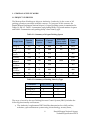
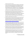
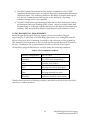
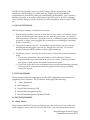
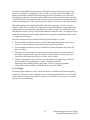
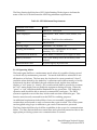
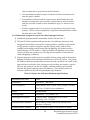
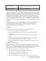
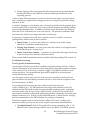

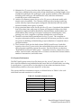


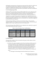


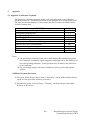
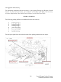

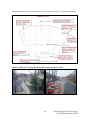
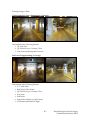
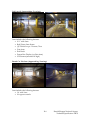
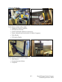
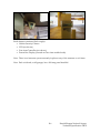
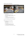
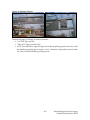
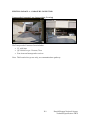
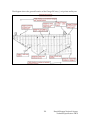
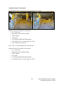
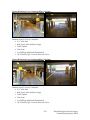
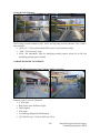
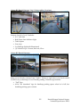
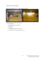
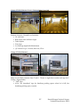
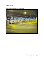
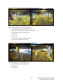
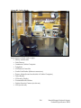
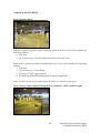
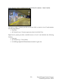
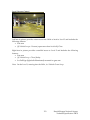
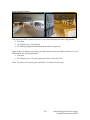
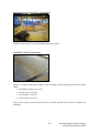
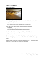
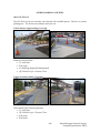
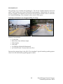
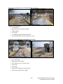
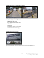
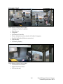
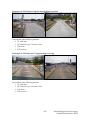
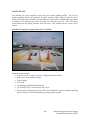

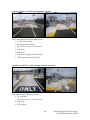

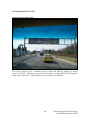
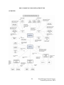
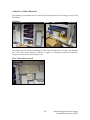
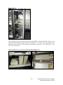
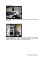

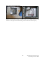

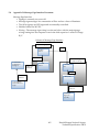

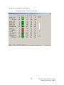

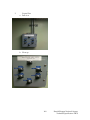


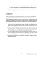
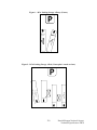
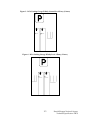
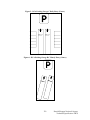

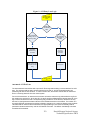
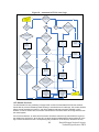

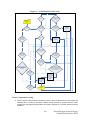


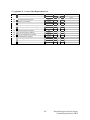
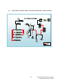


![[1 ] Oracle® Enterprise Manager](http://vs1.manualzilla.com/store/data/005669073_1-0396df232df5e560fdd03210f5126330-150x150.png)