1
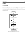
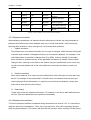
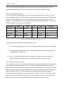
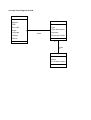
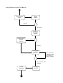
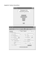
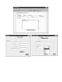
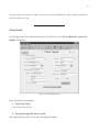
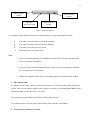
Summary
-I-
Summary
The main aim of this project was to produce an information system for AIS that would handle the
entry and case details for their clients. At the beginning of the project, the minimum requirements,
were defined as having to produce:
•
An executable system
•
Use Case Diagrams
•
Appropriate UML diagrams
•
A user manual
The actual information system was split into two parts, the database and the user interface. The
database was fully implemented and provided a firm basis for the data that AIS needed to record,
but the user interface was only partially accomplished, in that a prototype was produced. However,
a set of Use Case and UML diagrams were produced, as well as the user manual and even though
the user interface was not fully implemented, AIS decided to use the underlying database.
Acknowledgments
- II -
Acknowledgments
I would like to thank all the staff at AIS who have been constantly bugged by my questions and
enquires. I would also like to thank all my friends who had to put up with me stressing out and who
I didn’t see for many weeks due to this project.
Table of Contents
- III -
Table Of Contents
Chapter 1
1.1
Background
1
Introduction to Advocacy and Interpreting Service
1
1.1.1
Definition of Problem
1
1.1.2
Information Technology in the Organisation
2
1.2
Project Proposal
2
1.3
Project Objectives
3
Background Research
5
2.1
Introduction
5
2.2
Brief History of Systems Development Methodology
5
2.2.1
Traditional Systems Development Life Cycle
5
2.2.2
Structured Methodologies
6
2.2.3
Object Oriented Development
7
Chapter 2
2.3
Chosen Methodology
7
2.4
Method
9
Analysis
11
Introduction
11
3.1.1
11
Chapter 3
3.1
Analysis Techniques Used
3.2
Analysis of AIS
12
3.3
Functional Requirements and Non-Functional Requirements
13
Design
14
4.1
Database Design
14
4.2
Conceptual Design: Entity Relationship Modelling
15
4.2.1
Entities and Attributes
15
4.2.2
Relationships
16
Chapter 4
4.3
Logical Design
16
4.3.1
Primary Keys
16
4.3.2
Foreign Keys
16
4.3.3
Database Anomalies
17
4.3.4
Database Normalisation
17
4.3.4.1 First Normal Form
18
4.3.4.2 Second Normal Form
18
4.3.4.3 Third Normal Form
19
Table of Contents
4.3.5
4.4
- IV -
4.3.4.4 Boyce Codd Normal Form
19
Logical Schema
19
User Interface Design
20
Development and Testing
21
5.1
Choice of Development Package
21
5.2
Physical Design of Database
22
5.2.1
Schema Implementation
22
5.2.2
System Output Implementation
22
Chapter 5
5.3 Interface Implementation
5.3.1
5.4
Chapter 6
22
Structured Query Language
22
5.3.1.1 SQL within the system
23
5.3.2
Data Validation
23
5.3.3
Security
24
5.3.4
HCI issues
24
Testing
26
5.4.1
System Testing
26
5.4.2
Real Data Testing
26
Evaluation
27
6.1
Evaluation of Prototype and Recommendations
27
6.2
Evaluation of Objectives
27
References
29
APPENDICES
Appendix A: Reflections
Appendix B: Documentation from AIS
Appendix C: UML Diagrams for Analysis
Appendix D: Initial ER Diagram
Appendix E: Logical Schema
Appendix F: UML Diagrams for Design
Appendix G: Implemented Tables with Attributes
Appendix H: Report Output
Appendix I: Data Validation Table
Appendix J: User Manual
Appendix K: Interface Screen Shots
Chapter 1 – Background
-1-
1 Background
1.1 Introduction to Advocacy and Interpreting Service
Advocacy and Interpreting Service (AIS) is a charitable organisation. It was established in 1993
and is funded by the Health and Social Services. Based in Leeds, they mainly provide a
translation, interpreting and advocacy service to the Chinese, Bangladeshi and Pakistani
community in the Leeds area. They aim to develop greater access to health; social care and
community care services to these communities by liasing with voluntary and statutory
organisations. AIS’s main belief is that,
“everyone is entitled to receive a service in which their religious, cultural and social needs are
respected”.
(AIS Annual Report 1999-2000)
AIS currently holds details on over 700 clients, with over 200 of them being regular clients. They
provide a drop-in service for clients to attend when they need help. Also, members of staff regularly
accompany clients to places where they may need the help of an interpreter, e.g. GP
appointments, hospital appointments and dental appointments. Currently there are seven full time
members of staff, which includes five bi-lingual co-ordinators, the AIS administrator and the service
manager Mussarat Khan. Due to the limited number of staff and the high demand for the service
that AIS provides, they also have a number of volunteers who help the bi-lingual co-ordinators.
These volunteers essentially carry out the same job as the co-ordinators (translation, interpreting
etc.) whilst also handling any day-to-day administration work.
1.1.1 Definition of Problem
I joined AIS in September 2000 as a voluntary worker. After a period of time it became apparent to
me that the majority of administration work was done on paper. I thought that this was a very
cumbersome method. All the client’s details and their case details were held in a file and were
stored alphabetically. Each time a client came to AIS they were marked down in a client entry
book. The staff encountered three major problems with this:
I. Sometimes the files were misplaced making it difficult to find.
II. At the end of every month a client entry sheet had to be filed in, showing the breakdown of
the clients that have come to AIS and their problems. The process of producing this
document was to go through the client entry book and mark down every client along with
Chapter 1 – Background
-2-
his or her case details. This is a slow and tedious task, and sometimes problematic as the
client entry book is never filled in chronologically.
III. When AIS organises events, such as a talk on nutrition and diet, or the Annual General
Meeting, letters need to be sent out to all the regular clients. This involved going through
the client entry book to find the regular clients and then going to each client’s file to find
their address. This again was an extremely slow and cumbersome method.
Therefore after speaking to several members of staff and the service manager, Mussarat Khan,
they agreed that they needed a more efficient method of storing and retrieving client’s data.
1.1.2 Information Technology in AIS
Currently AIS has two computers. However after inspection they were discovered to be very old
and hence extremely slow. The specifications are detailed in figure 1.1
PC 1
PC 2
486 DX, 33Mhz
Pentium 133
HDD: 400MB
HDD: 808.91MB
3½ Floppy Disk Drive
3½ Floppy Disk Drive
5¼ Floppy Disk Drive
4xCD Rom
15 inch VGA Monitor
15inch VGA monitor
Printer: Hewlett Packard Deskjet 500C
Printer: Hewlett Packard Deskjet 870Cxi
Windows 3.1, MS Works
Windows 95, Office 95
Figure 1.1: Specifications of current computers in AIS
As a result of the low specifications of the two computers currently used in the office, they are
treated as ‘glorified typewriters’. They are only used for basic administration work, such as typing
reports and letters, and creating posters. However the organisation is currently in the process of
purchasing a new computer. After advice from me and in respect to the organisation’s budget a
new computer will be purchased. The specifications of this computer are detailed in figure 1.2.
1.2 Project Proposal
This project is the analysis and design of an information system for AIS. This involves two parts:
I. Designing and implementing a database for the clients details and their case details
Chapter 1 – Background
-3-
II. Designing and implementing a user interface to access the database.
Due to the fact that AIS will be purchasing only one reasonable computer, with the other two
computers currently used in the organisation being extremely slow, the database and user
interface will run on the new computer only. This means that the database will be a simple client
side database.
Pentium 3, 800Mhz
128MB Memory
HDD: 20.4 GB
3½ Floppy Disk Drive
48x CD Rom
19 inch Monitor
Graphics Card: Volcano 32MB TNT2 M64 AGP
56K Modem
Iomega Internal 250MB Zip Drive
Windows ME, Office 2000 Premium Edition
Figure 1.2: Specifications of new computer
1.3 Project Objectives
The objectives of the project are as follows:
I. Identify the requirements
The initiation of the project will begin with the analysis of the organisation so that the
requirements of the organisation can be identified.
II. Model the requirements
After studying Unified Modelling Language (UML), I believe that these concepts are
extremely useful in the development of an information system. Therefore a selection of UML
diagrams and entity-relationship diagrams will be used for the database. This will help the
modelling of the requirements for this project.
III. Design and implement an information system
An appropriate development methodology will be chosen and used throughout the project
(see chapter 2). The design of the information system is related to objective II (above) with
special emphasis placed on designing a database using Access 2000. Access 2000 has
Chapter 1 – Background
-4-
been chosen because the new computer will have Access 2000 installed, and also because I
am familiar with this software. The user interface will be developed using Visual Basic 6 (VB).
(There are more details on the two packages used in chapter 5). This is because the
University has VB on their machines and VB is the most widely used software development
package in the world. Also I have chosen VB, as I would like to learn the programming
language.
Chapter 2 – Background Research
-5-
2 Background Research
2.1 Introduction
Before any analysis or design takes place, it is important that a development methodology is
chosen. This chapter will explain the importance of using a development methodology and also
briefly describe three different methodologies, Systems Development Life Cycle (section 2.2.1),
Structured Methodology (section 2.2.2) and Object Oriented Development (section 2.2.3). Finally in
section 2.3, an appropriate methodology will be chosen with the method described in section 2.4.
2.2 Brief History of Systems Development Methodology
Before the use of system development methodologies, systems development was a ‘hit or miss’
affair. Some development projects would succeed whilst some would fail. It was a big risk when an
organisation wanted to implement a systems development project. The main risks involved were:
•
Time
•
Money
•
Probability of Failure
•
Data Loss
Systems development methodologies were introduced in response to the need of reducing the
risks involved with systems development. This gave the designers a set of tools and techniques to
use which provided a more systematic approach, increased predictability in results, better
management of resources (thereby reducing the costs) and improved co-ordination between the
designers and the users. The result of the utilisation of a systems development methodology is that
everybody engaged in the project is working from the same methods, using the same
documentation and therefore no misunderstandings or miscommunication will occur, resulting in
fewer mistakes. This is extremely important in today’s business world as the business environment
is becoming more and more complicated whilst technological advances continue to accelerate.
2.2.1 Traditional Systems Development Life Cycle
One of the first systems development methodologies that were used was the traditional system
development life cycle (SDLC). Avison and Fitzgerald (1995) identify six main stages in the
traditional SDLC, where each stage has an output that leads onto the next stage. The stages are:
•
Feasibility study
•
Systems investigation
Chapter 2 – Background Research
•
Systems analysis
•
Systems design
•
Implementation
•
Review and maintenance
-6-
This methodology has been used for over thirty years, and was considered better than having no
methodology at all. The documentation that accompanies each stage ensures that the original
specifications are correct and also ensures that there is good communication between the users
and the developers. Also, because of this continuous feedback between the user and developers,
the time and cost of the development process can be controlled.
However, the documentation that this methodology produced may become too complex for users
to understand. Also many developers felt that producing the documentation was a chore and
subsequently poor documentation was produced. The way that the outputs for each stage were
defined before the stages were complete made the methodology inflexible. And because the
methodology was step-by-step process with no iteration, if the investigation and analysis stages
were poorly executed, or the requirements of user changed, then the result would be a poor or
incomplete system.
2.2.2 Structured Methodologies
Structured methodologies are one of the most widely used approaches to designing information
systems. It takes a top-down view of an organisation and decomposes it into a set of modules,
which makes a complex organisation more manageable. The methodology is well documented with
a consistent set of procedures at all stages, which the users are also involved with. There are
many structured methodologies, each with it’s own set of procedures. For example SSADM
(Structured Systems Analysis and Design Method) has the following stages:
•
Feasibility
•
Investigation of the current environment
•
Business systems options
•
Definition of requirements
•
Technical options
•
Logical design
•
Physical design
(Clark 1999)
Each of these stages has it’s own set of procedures and techniques that may use a number of
development tools. However these procedures are very strict, with the emphasis placed on the
Chapter 2 – Background Research
-7-
documenting the whole process. This formalises the development process, and gives it structure,
thereby making the development of an information system for a complex organisation more
manageable. Unfortunately, the rigid structure of this methodology means that the development
cannot deviate from its original aim. It assumes that the needs of users can be defined from the
outset, as there is no iterative cycle to reassess the users’ requirements. Also, structured
methodologies tend to produce documentation that is too technical for the users to understand and
hence poor communication can occur between the users and developers.
2.2.3 Object Oriented Development
Object-oriented development (OOD) grew from object-oriented programming languages. Objects
are basically reflections of ‘things’ in the real world, e.g. a chair is an object. It may have different
attributes such as price, colour and weight, and it may belong to a higher class, or a generalisation,
such as ‘furniture’ that may contain other objects such as table and desk. This type of modelling of
the real world is the basic principle that OOD uses.
OOD has many of the principles contained in structured systems development, but with five main
differences:
•
Encapsulation of process within data in both the systems structure and the development
methodology
•
Objects in the system are assigned ‘responsibilities’
•
Modelling of the problem domain throughout development
•
Emphasis on design and code reuse with extensibility
•
Incremental and iterative development
(Booch 1994)
Recently, OOD methodologies have been growing in usage due to the popularity of object-oriented
programming languages. The promises of reusable components, user involvement and a system
that can easily adapt to the users’ ever-changing needs, have enticed many developers. However,
it has been noted that OOD is not suitable for the redevelopment of legacy systems (Bruegge and
Dutoit 2000), where rebuilding them to object-oriented designs and retraining users would cost a
considerable amount of money and time.
2.3 Chosen Methodology
When choosing the methodology needed for this project I needed to consider the following points:
•
Flexibility
•
Time
Chapter 2 – Background Research
•
-8-
User interaction
Dearnley and Mayhew (1983) proposed the inclusion of prototyping into the SDLC. The use of
prototypes gives the user and designers a ‘taste’ of the system to come. Figure 2.1 shows how
prototyping can be integrated into the SDLC.
Maintenance
User
request
Evaluation
Feasibility
Operation
Investigation
Implement
Test
Consider
Prototyping?
Design
prototype
Program
Analysis
Design
Yes
Use
prototype
Final
proposed
design
No
No
No
Refinement
or new
prototype
required?
Investigate
Analyse
Figure 2.1: The revised system life cycle with prototyping [Dearnley and Mayhew 1983]
Use of prototyping can save time, especially for the analysis and design stages of development.
For a user to see and test a prototype gives them a feel for the system and can confirm that the
developers have captured the users requirements correctly. Whilst simply producing a final system
would mean that that would be the first time that they use, or even see, the system, and hence any
dissatisfaction with it, may be too late.
The use of prototypes can generate more information about the users and their requirements than
just analysing them. Also because of the continuous communication between the users and
developers there is increased user interaction.
Chapter 2 – Background Research
-9-
This methodology satisfies all three criterion outlined above. SDLC with prototyping is flexible as it
is an iterative approach to designing an information system. Any changes to the users
requirements or any errors or misunderstandings during the investigation phase can be identified
and rectified with the prototypes.
The limited time available to me means that development should be rapid, and Avgerou and
Cornford (1998) agree that the prototyping approach needs to,
“undertake extremely rapid construction and revision of systems”
I believe that successful user interaction is one of the fundamental aspects of designing a suitable
system. SDLC with prototyping provides this user interaction throughout the development process.
Dearnley and Mayhew also suggest that an added advantage to this approach is that the
developer can learn how to design and develop a system and learn how to overcome technical
problems. This would be ideal for me, as I have never taken on a project of this magnitude before.
2.4 Method
Figure 2.2 shows the stages that I will conduct throughout this project. It is a simplified diagram of
Figure 2.1. Here each of the stages lead onto the next stage, with each stage having a series of
outputs.
Investigation
Design
Development
UML Diagrams
Functional Requirements
UML Diagrams
ER Diagrams
Logical Schema
Physical Schema
Prototype
Test Prototype
Figure 2.2: Stages and outputs for project
Chapter 2 – Background Research
-
- 10
As detailed in figure 2.2, the outputs for the investigation and design phases include UML (Unified
Modelling Language) diagrams. Using UML will help support the development of the system and
also enable documentation of the information acquired for future reuse. It is easy to use and
understand, whilst at the same time, also expressive of the system/organisation that it models.
UML is particularly suitable for object-oriented methodologies, but Priestley (2000) believes that
UML can be,
“… productively used with a wide range of processes”
Booch (1994) also suggests that UML is suitable for a methodology that is….
“…use case driven, architecture-centric, iterative and incremental”
Because of these factors, I believe that incorporating UML, in the prototyping methodology will be
ideal.
Chapter 3 – Analysis
- 11 -
3 Analysis
3.1 Introduction
System analysis is one of the fundamental stages in systems development. Without a proper
understanding of the organisation the information system is intended for, and without proper
consultation of their requirements, the resulting information system may be useless. This chapter
will provide a brief overview of the analysis processes used and a summary of the findings.
3.1.1 Analysis Techniques Used
Investigations into AIS used interviews with the manager, Mussarat Khan, and staff members. Also
my own personal experience of working in the organisation was used to a limited extent. However,
it was important that I did not put too much emphasis on my voluntary work at AIS because I would
not be a long-term user of the system and also because my experience in the organisation was
limited to seven months. Existing documents and paperwork were used (see Appendix B:
Documentation from AIS) as a guideline for how AIS operated and what type of documentation AIS
needs to produce. Observations of how the staff operated also gave an insight into the workings of
AIS.
The information gathered from these investigations produced a number of key processes (section
3.2). These processes were then mapped onto Use Case diagrams and class diagrams. This
provided an abstract view of AIS, which could be developed further in the design stage.
3.2 Analysis Of AIS
Through the analysis techniques above, four key processes were identified:
I. New Clients – New clients need to be created and recorded using an appropriate method.
Currently a New Client Form is completed for any new clients wishing to use AIS.
II. Client Details – Details of clients should be able to be retrieved quickly. The current system
involves each client’s details, along with their case details held in a file. Every client is filed
alphabetically in a filing cabinet with each filing cabinet segregated by origin.
III. Case Details – Clients coming to AIS with problems need to have their case details
recorded along with the appropriate documentation to accompany the case, e.g.
photocopies of letters, forms and bills.
Chapter 3 – Analysis
- 12 -
IV. Management information – monthly reports of client entries and client cases need to be
produced by the workers. Also, an annual report needs to be produced showing the
breakdown of client entries and cases throughout the year. Finally a list of clients name and
addresses need to be produced for mailing purposes.
AIS System
Create New
Client
Generate
Report
Client
Worker
Create Case
Extends
View Client
Details
Uses
Co-ordinator
View Case
Details
Figure 3.1: General Use Case for AIS system
Client List
Includes
Generate
Report
Includes
Worker
Includes
Client Entry
Report
Annual
Report
Figure 3.2: Generate Report Use Case
Volunteer
Chapter 3 – Analysis
- 13 -
These four processes were first drawn up to provide two USE case diagrams (figure. 3.1 and figure
3.2). One represented an abstract representation of the system, whilst the other showed a slightly
lower level of abstraction for the Use Case Generate Reports.
A concept level class diagram was also drawn (Appendix C: UML Diagrams for Analysis). This was
based on the ER Diagram for the database (see Section 4.2.1: Entities and Attributes), where
entities are the same as classes.
3.3 Functional and Non-functional Requirements
From the four key processes detailed above and also the analysis of AIS, the functional and nonfunctional requirements of the information system can be identified:
Functional Requirements
1. Client Details - The system must:
•
Provide a record structure for the clients of AIS, which will include their personal and
case details.
•
Allow client details to be created, modified, deleted, searched and printed.
2. Generation of Reports – The system must:
•
Provide the utilities to preview and print the following reports:
I. Breakdown of overall client entries for the year (for the Annual Report)
II. Clients Monthly Record Sheets
III. Client List according to origin
Non-functional Requirements
1. Provide a user-friendly interface that will be easy to use for novice computer users.
2. Produce all reports automatically and therefore in a shorter period of time than the current
paper based system.
3. Provide a user manual.
4. Provide a security system to prevent unauthorised access.
Chapter 4 – Design
- 14 -
4 Design
4.1 Database Design
Atzeni and Ceri (1999) propose the phases of database design (figure 4.1) that should be followed.
Beginning at the definition of the application of requirements, as detailed in chapter 3, the three
step by step phases can be completed. The following sections will be concerned with the
conceptual and logical design of the AIS database. Whilst the physical design stage will be detailed
in the following chapter.
Application
requirements
Database
design Conceptual Design
CONCEPTUAL SCHEMA
Logical Design
LOGICAL SCHEMA
Physical Design
PHYSICAL SCHEMA
Database structure
and related documents
Figure 4.1: Phases of database design [Atzeni & Ceri 1999]
Chapter 4 – Design
- 15 -
4.2 Conceptual Design: Entity Relationship Modelling
This project used the Entity relationship (ER) model along with ER diagrams to graphically display
the conceptual model of the database. This gives a high level of abstraction of the organisation and
the data it needs to store. The output for this phase is the conceptual schema, which in the case of
ER modelling will be the ER diagram.
There are three main components of the ER diagram:
I. Entities – “a ‘thing’ in the real world with an independent existence” (Elmasri and Navathe
2000). For example, a car can be called an entity.
II. Attributes – these are the properties that describe the entity. For example, for a car the
associated attributes could be the make, model, engine size, colour etc.
III. Relationships – this is the relationship between two or more entities. For example, a person
may own a car.
Appendix D: Initial ER Diagram, shows the ER diagram based on the information in section 4.2.1
and section 4.2.2.
4.2.1 Entities and Attributes
To identify the entities and attributes, documentation from AIS was used along with advice from
staff at AIS. The following three points details the entities and attributes that should be modelled.
•
Each client’s details must be stored; Name, address, date of birth, ethnic origin, language,
partner, children and phone number. The main source of this came from the Client Details
form (Appendix B: AIS Documentation).
(Note that the Client Details form contains extra information, but staff told me that this
information was rarely if ever filled in)
•
Each client’s case details must be stored. The case details include: Case date, case
summary, case type, abbreviation of the case type and if there are any photocopy details
with the case. This information was taken from the client entry book.
•
Workers details must be stored: Name and worker status, that is, is he or she a volunteer or
a co-ordinator. Also, if the worker is a volunteer, who is his or her co-ordinator.
From the above descriptions, the three entities, CLIENT DETAILS, CASE DETAILS and
WORKERS could be identified, along with their associated attributes.
Chapter 4 – Design
- 16 -
4.2.2 Relationships
The relationship between each entity is described below. These relationships are derived from
interviews with the staff and general observation.
•
CLIENT to CASE (one to many) - A client can have many cases, but case can only belong
to one customer
•
WORKER to CASE (one to many) – A worker can work on many cases, but a case is only
handled by one worker
4.3 Logical Design
The next stage in database design is to map the conceptual design of the ER diagram to the actual
database to produce the logical schema (see Appendix E: Logical Schema). As a relational
database will be used, normalisation of the logical schema should be carried out to verify the
integrity of the design.
4.3.1 Primary Keys
It is important when developing a relational database that all tuples within a table are unique. This
is to avoid any ambiguity or confusion. Therefore, primary keys are used to preserve the
uniqueness of tuples. The primary key in a table is the one attribute that must have a value that is
unique for each tuple. Any attribute can be a primary key, however it must be chosen carefully. For
example, people’s names might not always be unique.
For the Client Details Table, the original primary key was intended to be the national insurance
number (NI attribute) as this is unique for every person. However it became apparent after
analysing the current client records that the NI number is not always known. This is a problem as a
primary key can never be a null value. Therefore, separate primary key attributes were created for
each relation to preserve database integrity.
4.3.2 Foreign Keys
As shown in the E-R diagram in Appendix E: Logical Schema, each entity is related to another
entity. To represent this in a database a table must reference another table. The method of
achieving this is to create a foreign key that references the primary key in the appropriate table.
For example, to map the relation Client Details to Case Details, a foreign key called CaseID is
created in Client Details. This references the primary key in the Case Details table , which is also
called CaseID)
Chapter 4 – Design
CaseID
- 17 -
Case Type
Abbreviation
Case Date
Summary
Photocopies
1
Housing
HG
12/01/01
Advice on council
housing
No
2
Benefits
B
01/03/01
Filled in JSA form
Yes
3
Benefits
B
18/04/00
Made enquires about
Income Support
No
4
Immigration
IM
21/3/01
Translated statement
Yes
5
Health
H
30/1/01
Doctor’s appointment
at LGI
No
Figure 4.2 The relation Case Details with anomalies
4.3.3 Database Anomalies
When designing a database it is important that the tables do not contain too many attributes as
problems and inefficiencies of the database may occur. Ullman and Widom (1997) identify the
following three problems; I have used figure 4.2 to illustrate these problems:
I.
Update anomalies
This problem can occur when information for one tuple is changed, whilst the same information
in another tuple remains unchanged resulting in an inconsistent database. For example, if the
case abbreviation for benefits is changed from ‘B’ to ‘BEN’, and only CaseID 2 is changed,
there would be an update anomaly, as the applicable information for CaseID 3 has not been
changed. Also, inserting a new client in this relation may prove problematic as he or she may
not have any case details and so the other attributes in that tuple will need to contain null
values.
II.
Deletion anomalies
When some attributes for a tuple need to be deleted then other information for that tuple may
be lost. For example, if the case details for CaseID1 were to be deleted then the case type,
Housing along with the abbreviation, H, would be removed from the database, unless there
was another case that involved housing.
III.
Redundancy
Tuples may contain the repeated information. For example, in the above table attributes such
as Case Type and Abbreviation are repeated unnecessarily.
4.3.4 Database Normalisation
To limit the problems identified in database design as described in section 4.3.3, it is important to
adopt the process of normalisation. There are six normal forms, each with increasingly stringent
tests to compare tables to. This section will deal with the first three forms and Boyce Codd normal
Chapter 4 – Design
- 18 -
form, as fourth normal form and fifth normal form are for multivalued dependencies and join
dependencies respectively and hence are irrelevant to this project’s database design
4.3.4.1 First Normal Form (1NF)
Elmasri and Navathe (200) describe 1NF as concerned with ‘relations within relations’. That is,
values of attributes within a relation should be atomic and not multivalued. When considering the
design of the AIS database, it came to my attention that client’s may speak more than one
language. For example Chinese clients may speak both Cantonese and Mandarin. Therefore the
situation in figure 4.2 may occur in the database
Client Name
Liu Jia Wen
Simon Chan
Miran Dodd
Lin Biao
Address
DOB
19 Regent Park
167 Bellvue
Road
5 Stanway
View
85 Burley Road
Sex
Origin
Language
12/04/56
F
Chinese
Cantonese, Mandarin
01/06/45
M
Hong Kong
Cantonese
30/9/65
M
Pakistani
Urdu
14/05/72
M
Chinese
Mandarin
Figure 4.3: Client Details Table not in 1NF
To place this relation in 1NF the following steps were taken:
I. A new table, Language, was created. This will hold the languages that each client speaks.
II. The primary key of ClientDetails table, ClientID was referenced in the Language table,
using ClientID as a foreign key.
III. Now, if a client speaks more than one language, the details are simply entered in the
Language table. As both tables cannot contain multiple values, they are in 1NF.
4.3.4.2 Second Normal Form (2NF)
For a relation to be in 2NF, it must be in 1NF and also the non-trivial dependencies in that relation
must be full functional dependencies. That is, the functional dependencies within a relation, if
broken down, should not be able to form other functional dependencies. For the design of the AIS
database, primary keys, with single attributes, were created for each table. Therefore the tables
are automatically in 2NF, as the other attributes in each table depend on that primary key.
Consider the table ClientDetails. Here the primary key is ClientID. Therefore if ClientID is known
then the rest of the Clients Details will be known. Since ClientID can only contain single values,
and there are no other keys that determine the other attributes, this table is in 2NF.
Chapter 4 – Design
- 19 -
4.3.4.3 Third Normal Form (3NF)
3NF tests to see if any attributes in a relation are determined by attributes which are not keys. If
this is true then the relation is not in 3NF. On observation of the current relations it was discovered
that just one relation was not in 3NF.
Case Details relation – here, apart from the primary key determining all the other attributes, the
attribute Case Type also determined the attribute TypeAbbreviation.
To place this table in 3NF it was necessary to decompose them into further tables. This method is
described below:
I. For every dependency that is determined by a nonkey attribute, introduce a new relation.
For the CaseDetails relation a new relation CaseType was created.
II. Place the all the nonkey attributes and the attributes that they determine into the new
relation. The new relation CaseType contained the attributes Type and TypeAbbreviation.
III. Now the original relation (CaseDetails) and the new relation (CaseType) are in 3NF.
4.3.4.4 Boyce Codd Normal Form (BCNF)
This is the strongest normal form as it eliminates all anomalies. If a relation has more than one
attribute that could be the primary key (the candidate key) then each attribute value should depend
on both the primary key and the candidate key.
For the majority of relations in 3NF are also in BCNF. After inspection of my tables all of the
relations were in BCNF.
4.3.5 Logical Schema
Along with the changes made in the above sections, the following changes were also made to the
conceptual schema, to produce the logical schema:
•
The Client entity was renamed ClientDetails to be more descriptive of the information it
contained.
•
The Case entity was renamed CaseDetails to be more descriptive of the information it
contained.
•
The Name attribute of ClientDetails was split into FirstName and Surname. This was to limit
the problems with Chinese names, where people’s surnames come first. It was deemed
more ‘safe’ to explicitly declare a first name and surname. Also these two attributes can be
used as a search criterion separately.
•
The Address attribute of ClientDetails was split into Address1, Address2, Address3, and
Postcode. Splitting this attribute allowed increased consistent input by the users and also
because the postcode was to be one of the search criterions.
Chapter 4 – Design
•
- 20 -
An extra entity MobPhone (mobile phone number) was placed in the ClientDetails table.
This was to reflect the ever-increasing use of mobile phones.
•
TypeAbbreviation in CaseType was shortened to TypeAbbrev as the original name was too
long.
•
Looking at the initial ER diagram there was a problem with the Workers entity. Going back
to the analysis stage, both volunteers and co-ordinators can work on a case, with each
volunteer being supervised by a co-ordinator. There are also reports that are generated for
each Coordinator and their associated case. If a coordinator supervised a volunteer and a
volunteer handles a case, the case also belongs to the volunteer’s coordinator. I decided to
split the Worker entity into Volunteer and Coordinator, each being referenced by the
CaseDetails table. Then a new entity, Vol_Coord, was introduced to map volunteer to the
co-ordinator.
4.4 User Interface Design
In the design stage, class methods need to be identified for the different classes (see Appendix F:
UML Diagrams for Design). Looking at these methods, it was noted that the methods for the class
Client and the class Case were identical. The same functions, such as AddNew() and Save(),
would need to be implemented in both classes. Therefore it was logical to simply create these
functions once and reuse them for different classes.
VB6 provides the encapsulation principles that are associated with object oriented programming
languages. A class module can be created which can contain data types and methods, called
properties in VB, and then instances of this class, called objects, can be created which can access
these methods.
NavigateButtons
MoveFirst()
MovePrevious()
MoveNext()
MoveLast()
Toolbar
AddNew()
Undo()
Edit()
Save()
Print()
Figure 4.4: NavigateButtons and Toolbar class with methods
Therefore two new classes were created, NavigateButtons and Toolbar (see figure 4.4). They had
no attributes, just methods. These methods could then be used on the client details and case
details.Other functions and methods were simply taken from the use cases and activity diagrams
that had been drawn up (see Appendix F: UML Diagrams for Design).
Chapter 5 – Development and Testing
5
- 21 -
Development and Testing
5.1 Choice of development package
As described in Chapter 1, the development of the information system had two sides,
•
The development of the database
•
The development of a user interface for the database.
I
It was decided that separate development packages would be used for the database and the user
interface respectively. The database would be developed using Access 2000 and the interface with
Visual Basic 6.
•
Access 2000
Access 2000 is a powerful, yet easy to use, relational database management system. It
incorporates many functions that were extremely beneficial to the implementation of the AIS
database. For example, primary keys could be automatically created; validation rules and input
masks could be easily created using the wizards; and a large selection of data types could be
used.
•
Visual Basic 6
Visual Basic (VB) is a high level, event driven programming language, which has evolved from
BASIC. VB was chosen mainly because of the limited time available for the development of the
information system and because using the prototyping methodology needed to use a
“powerful, interactive, high level language, which is easy to write and modify”
Dearnley and Mayhew (1983)
The graphical user interface that VB uses, provides the programmer with quick and rapid
response to code. The drag and drop methods of adding objects, saves hours of programming
time, whilst the effects can be seen straight away. Also, one of main objectives of this project
was to use and learn VB.
For my user interface to connect to the Access database, VB provides ActiveX Data Objects
(ADO). This new feature of VB6 has been promoted by Microsoft to become the de facto standard
for accessing data sources. ADO is an application interface that accesses the OLE DB, which in
turn accesses the underlying data. This is shown diagrammatically as a component diagram, in
Appendix F: UML Diagrams for Design
Chapter 5 – Development and Testing
- 22 -
5.2 Physical Design of Database
5.2.1 Schema Implementation
The logical schema (section 4.3) provided the basis for the AIS database. During the physical
design of the database, the logical schema was mapped onto Access to create the database.
However, apart from the actual implementation of the schema, extra details needed to be added,
such as the data type of each attribute and if the attribute is required or not. Appendix G:
Implemented Tables with Attributes, details each table with their attributes and the appropriate
details. Also, with regard to the search function that was detailed as one of the functional
requirements, indexes were created for certain attributes so that when searching for certain details,
quicker access could be gained. Finally, validation rules, for some attributes, were set so that
erroneous values are not entered into the database (for more details see section 5.2.5)
5.2.2 System Output Implementation
As detailed in chapter 3, reports need to be generated on the client entries and their cases. This
was implemented by firstly coding the SQL query in Access and then using the report function in
Access I was able to able to create and format the look of the report. This was then linked to the
appropriate query. VB provided functions to access other Microsoft products such as Access.
Therefore using this function it allowed the interface to access the chosen report, preview it and
print it if necessary. Appendix I: Report Output shows some sample reports and figure 5.1 shows
the SQL query to list all the Bengali client details.
SELECT [ClientDetails].[Surname], [ClientDetails].[Firstname],
[ClientDetails].[Sex], [ClientDetails].[Address1],
[ClientDetails].[Address2], [ClientDetails].[Address3],
[ClientDetails].[Postcode], [ClientDetails].[HomePhone]FROM
ClientDetails WHERE [Origin]=3;
Figure 5.1: Query selecting all the Bengali ClientDetails
5.3 Interface Implementation
5.3.1 Structured Query Language
SQL is currently the standard for RDBMS. It is both a data definition language (DDL) and a data
manipulation language (DML). The former part allowing users to create tables, indexes, constraints
and other database objects. The DML side allows data to be edited, deleted and created. SQL is
used throughout this system to create, edit and delete client details and case details, however this
section deals with the search function within the system.
Chapter 5 – Development and Testing
- 23 -
As detailed in chapter 3, one of the functional requirements was that users of the system would be
able to search the database for specific clients. Without this search function, users would have to
cycle through the entire database until they found the client that they needed.
5.3.1.1 SQL within the System
Currently the system can handle four search criteria, first name, surname, National Insurance
number and postcode. It was originally planned that only one of each criteria could be used by
itself, however after consultation with the staff at AIS, it was suggested that first names and
surnames may not be unique to a particular client, whilst the NI number and postcode may be.
However the NI number and postcode may not always be know. Therefore it was proposed that
any number of combinations of the four criteria could be used to search for a client.
There were two options of implementing the search function. The SQL statements could be
embedded into the code, with one statement for each possible combination of searches, or SQL
statements could be implemented at runtime, constructing an SQL statement dynamically.
With the use of UML, the approach to my information systems design meant that the code must be
reusable, therefore I chose the latter option.
The basic SQL statement, “SELECT * FROM ClientDetails Where…” is created and, depending on
which search criterion are chosen, the appropriate details are added on to the SQL statement to
complete it. Any combination of search criteria can be used and adding extra criteria is simple. If I
used the method whereby each SQL statement is coded into the program then adding extra criteria
would mean that many more SQL statements would need to be added. For example with four
search criteria, fifteen SQL statements would need to be created, if an extra criteria was added
then the total number of SQL statements needed would increase to thirty-one, if two more criteria
were added then sixty-three SQL statements would be need. An activity diagram in Appendix F:
UML diagrams for Design shows how this function works.
5.3.2 Data Validation
It is important that values entered into the database are validated. This is so that data throughout
the database remains consistent and comprehensible to the organisation, as well as avoiding any
user error. For example, a user may, accidentally, enter a client’s date of birth as 12/13/78, or a
user, when entering the ethnic origin of a client, may misspell the origin. Implementing data
validation involved two methods. Firstly, in the underlying database, validation rules were set for
the required attributes. Access had a facility for this, which made the creation of these rules simple.
Chapter 5 – Development and Testing
- 24 -
Secondly, validation rules were implemented in the user interface, through Visual Basic. This was
more complicated as some validation rules need to be coded. However Visual Basic does supply
some facilities that can aid validation. For example, the use of combo lists was used for the origin
and language, to avoid misspelling. Therefore when the user enters the first letter of the origin or
language a drop down list appears to show the possible values. Also the use of a mask box was
used so that only specific values, either letters or numbers, are entered in the correct format. For
some data validation activities, such as checking if a text has been entered, VB provided a Validate
event procedure, which is accessed before the information is passed on to the actual database.
Here the appropriate code was programmed into this procedure and called every time a button was
clicked, e.g. the Save records button.
Appendix I: Data Validation Table, shows the fields that needed data validation rules and how they
were implemented in Access and Visual Basic.
5.3.3 Security
One of the non-functional requirements of the system was that it would prevent unauthorised users
access the system. This was easy to implement, as the ADO control, when accessing the
database can specify a password. This was simply left as a text data type called Password. When
a user opens the program he or she is asked to enter the password. This is then passed to the
ADO control and used to open the database.
5.3.4 HCI issues
IBM produces a document with eleven design principles that a user interface should adopt. These
were followed during the design of the interface as described below.
•
Simplicity: Don’t compromise usability for function
The user interface must not be cluttered and users should be able to access the basic
functions easily and quickly. This was taken into account when implementing the main
command buttons. A toolbar, in the ClientDetails form was created which contained the most
used functions. Also the navigation buttons, for cycling through the client records was placed
below the data so that it was pleasing to the eye and easy to access.
•
Support: Place the user in control and provide proactive assistance
This was not implemented in the prototype but it is hoped that further prototypes can provide a
help function.
•
Familiarity: Build on users’ prior knowledge
Chapter 5 – Development and Testing
- 25 -
Through the analysis stage (chapter 3) it was discovered that all members of staff had previous
working knowledge of the Windows operating system. Therefore I sought to provide an
interface that had the same ‘feel’ to Windows and the programs that ran on this particular
platform. Menus were created in similar orders and graphical representations for icons and
buttons used similar pictures.
•
Obviousness: Make objects and their controls visible and intuitive
Using real world graphical representations for different functions means that users can learn
commands quickly and intuitively. For example in my user interface a picture of a printer for the
command ‘Print’ was used along with the text name of that command. Also the use of message
boxes, with the appropriate icon, e.g. an exclamation mark for a ‘warning message’, a question
mark for a message querying the user, was used so that users can, intuitively, understand the
message that the system is trying to portray.
•
Encouragement: Make actions predictable and reversible
The use of graphical representation, as described above, makes certain commands
predictable. For example, on the toolbar a computer disk icon is used to represent the save
function. As many other applications use the same icon for their save function, a user seeing
this icon would instinctively know it’s function and hence be predictable. Implementation of an
‘Undo’ function whilst editing or creating a client record and the use of message boxes asking
for confirmation of certain actions, makes actions reversible.
•
Satisfaction: Create a feeling of progress and achievement
Feedback from the interface reported on what the user had achieved. For example, after
saving a client’s details, a message box appeared which reported that the client’s details had
been saved.
•
Availability: Make all objects available at all times
It was not possible to implement this principle in the design of the user interface because
certain actions lead on to other actions. For example, you can only save a client’s details after
you have inputted them in.
•
Safety: Keep the user out of trouble
It is a fact that all users may make mistakes. Therefore it is important that user errors should be
reduced to the minimum. Chapter 5.1.3 describes the importance of data validation, and how
user error is controlled when entering data. Also confirmation of some actions, such as print,
save, delete is needed so that the users are sure of what they are doing.
Chapter 5 – Development and Testing
•
- 26 -
Versatility: Support alternate interaction techniques
As well as using the mouse, keyboard shortcuts were created for each button. Also the use of
the tab button could move the user from one control to the other.
•
Personalisation: allow users to customise
This principle was not implemented for the system as it was beyond the scope of what was
required. However, a recommendation for further prototypes would be the choice to change the
display of the interface according to the user’s preference.
•
Affinity: Bring objects to life through good visual design
A toolbar was used to prevent clutter in the main form. Also changes in colour of the input fields
meant that the user new that he or she was in the editing mode.
5.4 Prototypes
5.5 Testing
Even though I was using a prototyping methodology, testing of the system was ongoing throughout
the development process. After implementing a method I would test it to see if the functionality was
what was required.
At the end of the development of the first prototype, system testing and real data testing
(section5.5.1) was conducted (section 5.5.2). This was then compared to the functional and nonfunctional requirements detailed in section 3.3.
5.5.1 System Testing
Some members of staff at AIS tested the system. They essentially ‘played around’ with the system
and also tried to do their day-to-day activities on the system. The problems that they encountered
and the recommendations that they made are detailed in chapter 6.
5.5.2 Real Data Testing
A selection of client details and case details were entered into the system and the underlying
database. This was to trap any errors in the design of the database and the interface and to make
sure that data validation worked on both levels.
Chapter 6 – Evaluation
- 27 -
6 Evaluation
6.1 Evaluation of Prototype and Recommendations
After the testing of the prototype, the staff at AIS agreed that they liked the way that they could
navigate through the client records and client details. Also the save, edit and undo functions
worked fine. However the output of the print function for the client details and case details did not
produce the results that the staff were hoping for. When clicking the print button a print out of the
client or case details screen would be outputted. Staff noted that what needed to be outputted were
a few lines of text, and not the whole screen. One member of staff noted that using this print
function would waste a lot of ink. Also when printing the case details, it was expected that all the
client’s case details would be printed out and not just the case detail that you were currently
viewing.
Generation of reports was adequate, but a preview function should have been incorporated. Also
two types of reports had not been implemented yet, breakdown of overall client entries for the year
and the clients monthly record sheets.
Every body agreed that the search function worked well, but staff suggested that a further search
criterion be implemented. This was to search clients who had been to AIS within certain dates.
6.2 Evaluation of Objectives
Section 1.3 outlined the three main objectives for this project:
I. Identify the requirements.
II. Model the requirements.
III. Design and Implement an information system.
With regard to identifying and modelling the requirements, I believe that a thorough job was carried
out, even though the end prototype had several features that were lacking. I think that this was a
problem of time and a rush to produce the prototype. This was one of the disadvantages of using
the prototyping methodology which I seemed to fall for. However I still believe that the prototyping
methodology was extremely appropriate to this project. However as these objective were outlined
before a methodology was chosen, the third objective changed to “Design and implement a
prototype information systems”. However the minimum requirements did not change:
•
An executable system
Chapter 6 – Evaluation
•
Use case Diagrams
•
Appropriate UML diagrams
•
User Manual
- 28 -
It was originally hoped that at least two iterations of the prototype cycle would be followed.
However due to technical difficulties with Visual Basic on the Computers within Computing
department, the development process was delayed. Many of the components for Visual Basic,
such as the ADO interface, which was essential to the connection of the interface to the database
was inoperable. After inquiring with support about this problem they told me that they were fixing
the problem. Unfortunately the problem took about two weeks to resolve, therefore putting my
project behind schedule.
In the end only one iteration of the prototype was produced. However this prototype has given AIS
and me, a good understand and a good feel for the potential of the system.
References
- 29 -
References
AIS, AIS Business Plan 1999-2004, March 1999
AIS, AIS Annual Report 1999-2000, March 2000.
Angell I.O and Smithson, S, Information Systems Management Opportunities and Risks,
Macmillan, 1991.
Avgerou, C. and Cornford, T., Developing Information Systems Concepts, Issues and Practice,
Macmillan, 2nd edition, 1998.
Avison, D.E., and Fitzgerald, Information System Development: Methodologies, Techniques and
Tools, McGraw-Hill, 2nd Edition, 1995
Booch, G., Object-Oriented Analysis and Design, Addison-Wesley, 2nd edition. 1994.
Bruegge, B. and Dutoit, A.H, Object Orientated Software Engineering – Conquering Complex and
Changing Systems, Prentice Hall, 2000
Clark, M., Introduction to Information Systems (Lecture notes), School of Computing, Leeds
University, 1999.
Conell, J., Beginning Visual Basic 6 Database Programming, Wrox Press, 1998
Dearnley, P.A. and Mayhew, P.J., In favour of system prototypes and their integration into the
systems development life cycle, Computer Journal, Vol. 26 No.1, pp36-42, February 1983
Ekedhal, M. and Newman, W., Programming with Microsoft Visual Basic 6.0 An Object Oriented
Approach, Course Technology, 1999.
Elmasri, R. and Navathe, S.B., Fundamentals of Database Systems, Addison-Wesley, 3rd edition,
2000
IBM, Design Basics, www-3.ibm.com/ibm/easy/eou_ext.nsf/Publish/6
Johnson, O., Object Orientated Analysis and Design (Lecture notes), School of Computing, Leeds
University, 2000.
References
- 30 -
Larman, C., Applying UML and Patterns An Introduction to Object-Oriented Analysis And Design,
Prentice Hall, 1998
Roberts, S.A., Database Principles and Practice (Lecture notes), School of Computing, Leeds
University, 2000.
Stevens, P. and Pooley, R., Using UML Software engineering with objects and components,
Addiso-Wesley, Updated Edition, 2000.
Senn, J.A., Analysis and Design of Information Systems, McGraw-Hill Publishing Company, 2nd
edition, 1989
Ullman, J.D. & Widom, J., A First Course in Database Systems, International Edition, Prentice Hall,
1997
Appendix A: Personal Evaluation
Overall I think that my project was suitable and appropriate to what I wanted to do, but I did not
realise the amount of work that I would need to put in. I have never taken on a project of this size
before and I think that my lack of experience hindered my progress.
Time management is one of the areas that I was severely lacking in. It was not just that I never had
enough time to do a certain stage, but sometimes I spent too long on one stage. For example for
the database design stages, I constantly drew and redrew many ER diagrams.
Also because of my unfamiliarity with VB, I sometimes got stuck. I think that if I were to spend
more time at the beginning learning some VB and playing around with some of it’s controls then
when it comes to the actually development stage I would have been more prepared.
One of the fundamental requirements of using a prototyping methodology was that prototypes
should be created quickly.
Using the UML diagrams was extremely useful to me. I, personally, always seem to see things
more complicated than other people, but the UML diagrams were extremely helpful in providing an
abstract view.
Appendix B: Documentation From AIS
Appendix C: UML Diagrams for Analysis
General Use Case for AIS System
AIS System
Create New
Clients
Generate
Reports
Client
Worker
Create
Cases
Extends
Extends
View Case
Details
Uses
Co-ordinator
View Client
Details
Volunteer
Use Case for View Client Details
Navigate
Client Details
Includes
View Client
Details
Worker
Includes
Includes
Delete Client
Details
Includes
Print Client
Details
Includes
Search Client
Details
Edit Client
Details
Use Case for Generate Reports
Client List
Includes
Generate
Reports
Includes
Worker
Includes
Annual
Report
Client Entry
Report
Concept Class Diagram for AIS
Client
Name
Case
Address
Date
DOB
Phone No
Type
1
Origin
Language
Children
0…*
has a
Type Abbreviation
Summary
Photocopy Details
Partner
0…*
works
on
1
Worker
Name
Status
Co-ordinator Name
Appendix D: Initial ER Diagram
Children
Address
Name
Language
Origin
Client
Partner
Date of Birth
Phone No.
has
works on
Photocopy
details
Case
Name
Worker
Worker Status
Summary
Date
Coordinator
Name
Case Type
Type
abbreviation
Appendix F: UML Diagrams for Design
Activity Diagram for Use Case New Client
Click New
Client Button
Clear fields
Enter
Details
[Click Undo]
Undo
[Click Save]
Save
Error
Check
[Errors]
[No Errors]
Write to
database
Activity Diagram for the Find Method
Enter search
criteria
Error
Check
[errors]
[No errors]
Check no.
of search
criteria
Check which
search
criterion
[1> criteria]
[1 criteria]
Generate
part SQL
[No. part SQL = No.
criterion]
Check
database
Generate
full SQL
[No. of part SQL
statements does
not equal no of
search criterion]
Sequence Diagram for Use Case New Client
:Worker
:Interface
:Database
Create new client
Display New
Client Form
Enter client details
Save client details
Error check
client details
Ask for confirmation
Confirm save new client
Add new client
Save client
details
Component Diagram Showing Runtime Dependencies
User
Interface
ADO
Interface
ODBC
Driver
Database
Appendix G: Implemented Tables with Attributes
Table: CaseType
Name
TypeID
Type
TypeAbbrev
Type
Long Integer
Text
Text
Size
4
50
5
Details
Primary Key
-
Table: CaseDetails
Name
ClientID
CaseID
CaseDate
CaseSummary
VolunteerID
CoordinatorID
TypeID
Photocopies
Type
Long Integer
Long Integer
Date/Time
Memo
Long Integer
Long Integer
Long Integer
Yes/No
Size
Details
Primary Key
Foreign key
Foreign Key
-
Size
4
4
8
4
4
4
1
Table: ClientDetails
Name
ClientID
Surname
Firstname
DOB
Sex
NI
Partner
Children
MobPhone
Address1
Address2
Address3
Postcode
HomePhone
Origin
LanguageID
Type
Long Integer
Text
Text
Text
Text
Text
Yes/No
Yes/No
Text
Text
Text
Text
Text
Text
Long Integer
Long Integer
4
30
30
8
7
9
1
1
10
50
50
50
7
20
4
4
Details
Primary key
Indexed
Indexed
Input mask
Validation rule
Input mask
Indexed
Foreign key
Type
Long Integer
Text
Size
4
50
Details
Primary key
-
Type
Long Integer
Text
Size
Details
Foreign key
-
Table: Co-ordinators
Name
Co-ordinatorID
Co-ordinatorName
Table: Language
Name
ClientID
Language
4
50
Table: Volunteer
Name
Type
Size
Details
VolunteerID
VolunteerName
CoordinatorID
Long Integer
Text
Long Integer
4
50
4
Primary key
-
Table: Coordinator
Name
CoordinatorID
CordinatorName
Type
Long Integer
Text
Size
4
50
Details
Primary key
-
Table: Vol_Coord
Name
VolunteerID
CoordinatorID
Type
Long Integer
Long Integer
Size
4
4
Details
Primary key
Foreign key
Appendix H: Report Output
Appendix I: Data Validation Table
Table
ClientDetails
Field
Sex
Validation Rule
Only allow male or female
Method in Access
"m" Or "M" Or "F" Or "f"
Method in Visual Basic
Code
Or "Male" Or "male" Or
"Female" Or "female"
ClientDetails
DOB
Format should be in the
Input mask: 00/00/00;0;
Mask Box
Input mask: LL00\ 0LL
Mask Box
None
Combo List
None
Combo List
Input mask: 00/00/00;0;
Mask Box
None
Combo List
None
Combo list
form dd/mm/yy
ClientDetails
Postcode
Format should be in the
form
ClientDetails
Origin
Choice from the Origin
table only
ClientDetails
Language
Choice from Language
table only
CaseDetails
Date
Format should be in the
form: dd/mm/yy
CaseDetails
CaseType
Choice from Case table
only
CaseDetails
Worker
Choice from Worker table
only
Appendix K: Interface Screen Shots
Appendix J: User Manual
-1-
Main screen
On opening of the Client Details interface, the main menu screen is displayed (see below).
Figure 3: Main Screen
There are five option buttons that you can choose between, each opening a separate window, apart
from ‘Exit’, which exits the program. The following sections will detail each option button and it’s
associated window.
Create New Client
To add a new client, click the Add button. This will bring up the client details window. Notice that
all the test boxes are yellow and blank. This shows that you can now add a new client. Enter the
details of the client and then click the Save button to add the client to the database.
When entering the details you must:
1. Enter the details for First name, surname, sex, date of birth (DOB), origin and language.
2. Date of Birth must be in the format – day/month/year. For example for someone who was
born on the 18th April 1978 you would enter the details 18/4/78.
-2-
If at any time you decide not to add a new client, click the Undo button. This will take you back to
the Client Details screen.
Client Details
On clicking of the Client Details button, the Client Details screen (Error! Reference source not
found.) will appear.
Figure 2: Client Details Screen
Here you can do several things:
1. Add a new Client
(see Create New Client)
2. Navigate through the client records.
The buttons shown below are the main navigational buttons
-3-
Move to first
record
Move to last
record
Move to
previous record
Move to next
record
Figure 3: Navigation Buttons
You can also use the directional arrows on the keyboard to navigate through the records:
This takes you to the first record on the database
This takes you to the last record on the database
This takes you to the previous record
This takes you to the next record.
Note
•
If you are at the beginning of the database then the move to first record button and
first record button is disabled.
•
If you are at the end of the database then the move to last record button is disabled,
as is the move next record button.
•
Whilst in navigation mode, the save and undo options are disabled on the toolbar.
3. Edit client details
To edit the current client’s details, click the Edit button. You will notice that all the fields turn
yellow. Now you can edit the details of the client as you please. (see Create New Client) for the
input details that you need to have for a client.
If you want to save the edited client details, click the Save button.
If you do not want to save the edited client details, then click the Undo button.
4. View the case details for the client.
-4-
Clicking on Case Details button will take you to the Case Details screen (figure 2). This shows
the case details for the client. The controls are detailed in the Case Details Screen.
5. Print the client’s details
Click on Print will print the current client details screen to the attached printer.
6. Find a client
Clicking on Find will bring up the Find Client screen (see Find Client)
7. Delete the client’s details
This will delete the details of the client that are currently on the screen.
Warning – If you delete a client’s details then you will delete his or her case details as well.
8. Exit the window
Clicking on Done will exit this window and take you back to the Main Screen.
Case Details
On clicking of the Case Details button, the Case Details screen (figure 2) will appear.
Here you can do several things:
1. Add a new case
Clicking on the Add New button will, turn all the fields yellow and blank. Now you can add the
new case details for the client. To save the new case details, click the Save button.
When entering the details you must enter the details for case date, case type and case
abbreviation.
If at any time you decide not to add a new case, click the Undo button. This will take you back
to the first case’s details.
-5-
2. Edit case details
Clicking on the Edit button will, turn all the fields yellow. Now you can edit the current case
details for the client. To save the changes that you have made, click the Save button.
If at any time you decide not to edit the case details, click the Undo button. This will take you
back to the first case’s details.
3. Navigate through the Case records.
The main navigational buttons are exactly the same as the navigation buttons for the Client
Details screen (see Navigate through Client Details for more information).
4. View the client details for the case.
Clicking on Client Details button will take you back to the Client Details screen
5. Print the case’s details
Click on Print will print the current case details screen to the attached printer.
6. Delete the case details
This will delete the details of the case that are currently on the screen.
If there are any further cases for the client, the case details screen will be displayed, with the
next case’s detail.
If there are no more cases for the client, you will be returned to the Client Details screen.
7. Exit the window
Clicking on Done will exit this window and take you back to the Client Details screen.
Find Client
Clicking on the Find Client button on the Main screen, and also the Find button on the Client
Details screen will take you to the Find Client screen.
This screen allows you to search for a client depending on the criteria that you set it.
-6-
Figure 4: Find Client Screen
The criteria that can be used are:
•
First name
•
Surname
•
Postcode
•
NI (National Insurance Number)
Any combination of the above criteria can be used. Simply click on the associated check button(s)
and then enter the details. Next click the Find button. The number of client details matching the
criteria that you specified will be displayed, along with th option to view them. Clicking on Yes will
take you to the Client Details screen. This will only display the results of your search. To return to
the whole list of client details click View All.
Reports
Clicking on the Reports button on the Main screen, will take you to the Reports screen. Here you
can choose which reports you want to create and print.
The available reports are:
•
Client List
•
Client List by origin – this provide you the possible client origins currently in the database.
Select the report that you would like to print and then click the Print button to print out that report.