1
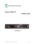
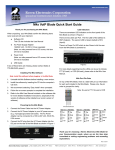
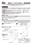
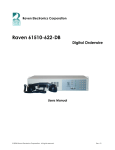
Raven 476-777 M4x VoIP Module
Technical Description
(Revision A.1)
Preface
Copyright Notice
©2011 Raven Electronics Corporation.
Trademarks
Raven Electronics and the Raven Electronics logo are trademarks of Raven Electronics
Corporation. All other brand and product names are trademarks, service marks,
registered trademarks, or registered service marks of their respective companies.
Important Notice
Raven Electronics reserves the right to make changes to its products without notice, and
advises its customers to obtain the latest version of relevant information to verify,
before placing orders, that the information being relied on is current.
Contents
Preface .......................................................................................................................................................... 1
Introduction .................................................................................................................................................. 2
Overview ....................................................................................................................................................... 2
Features Overview ........................................................................................................................................ 3
VoIP Networking Protocols ........................................................................................................................... 5
Raven Sample VoIP Applications................................................................................................................... 6
Networking Performance.............................................................................................................................. 7
Configuring a VoIP Backhaul ......................................................................................................................... 8
Specifications .............................................................................................................................................. 10
Block Diagram and Dimensions .................................................................................................................. 13
Introduction
This document describes the hardware and software of Raven Electronics 476-777 VoIP Module. The
intended audience of this document is technically proficient people who are interested in evaluating
and/or deploying the 476-777 VoIP module and need to understand the design and intention for that
evaluation. Further information and updates may be available on the Raven website at
http://www.ravencomm.com.
The 476-777 VoIP module is a small, low-power processing module which is designed to ease and speed
deployment of VoIP technology for Raven customers. It includes a DSP and support circuits, memory and
analog codec, and is delivered with the software required to create a functional VoIP device, all in a
small expansion module that can be deployed standalone in an M4x Mini-Blade or added to an available
slot in the customer’s existing M4x 8-port Blade.
Static Precautions
The 476-777 VoIP module is a static sensitive electronic device. Proper grounding and static
dissipation techniques must be observed when handling these boards.
Orderable Part Numbers
476-777
M4x VoIP Expansion Module
Overview
The basis of Raven’s M4x technology is the ability to mix different media types within a single
communication system. The 476-777 module adds VoIP capabilities to any of Raven Electronics’ flexible
M4x communication solutions. Based on an industry-leading, field-proven engine, our VoIP solution
provides a new dimension in power for the M4x product line.
Note: The 476-777 VoIP module is an evolving product with
active, on-going development. Please contact us for more
information on the current status of roadmap items.
Initially, our VoIP interface will address most of the basic needs of VoIP backhaul, leased-line
elimination, SIP and RTP endpoint support, and Radio over IP (RoIP) protocols. From there, our objective
is to provide true digital interoperability in both our voting configurations as well as our radio control
station configurations.
A hardware/software combination, the 476-777 module is a solution designed to be dropped into an
existing M4x Blade (See figure 1) or used as the foundation of a new M4x-based application. Based on a
dedicated and powerful Analog Devices Blackfin processor, the 476-777 module includes existing M4x
module interoperability, Ethernet connectivity, and a 48 kHz-capable stereo audio codec. The efficient
embedded operating system, network stack and control software are pre-integrated; out-of –the-box
the 476-777 module is immediately capable of creating digital conference calls or IP backhaul from
disparate analog or digital sources through M4x modules.
The intuitive Raven M4x Communications System Software (M4xCSS) was designed with ease-of-use and
a short learning-curve of paramount concern. Users have the option of physically connecting directly via
USB cable or remotely across Ethernet to a secure configuration web page. There are no POTs and no
DIP switches. Using the M4xCSS all configuration options are controlled in a Windows-familiar interface
with simple drag-and-drop features.
Figure 1- M4x Single Blade
Features Overview
The Raven 476-777 module includes a core set of included features and optional features that enable
further ease of integration into disparate complex systems.
Note: Some of these features may not be present in you
specific application.
Core VoIP Networking Protocols
SIP, SDP, RTP, STUN
Optional: SIPS, SRTP
Call Management
Supported Workflows: SoftPhone, Desktop Phone, POTS FXS , POTS FXO
Actions: place, answer, transfer, and disconnect calls; conference bridge/call;
generate DTMF, attended and unattended call hold; caller ID/message waiting/call
waiting.
Events: incoming call, peer on/off hold, peer disconnect, being transferred, detect
DTMF, registered/unregistered, etc.
Call management control via web page for remote control or M4xCSS for local
control.
Voice Engine
Codecs: G.711 (fully compatible), G.726 (16/24/33/40 kbps), G.722, DVI4
(narrow/HD/Ultra HD), Linear PCM, and iLBC supported with some limitations.
Algorithms: Gain, Automatic Gain Control (AGC), DC Blocker, High-Pass Filter, Voice
Activity Detector (VAD), Acoustic Echo Suppressor, Sample Rate Conversion, DTMF
(Generator/Detector), Call Progress Tone Generator, Custom Ring Tone Generator,
Comfort Noise Generator, Packet Loss Compensation
Optional Algorithms: Custom Tone Generator, Acoustic Echo Canceller , Line Echo
Canceller, Noise Reduction , Frequency Equalizer
Information Subsystem
Configuration Information Management
o File-based by default
o Can integrate with platform’s configuration style
Runtime Information Management (e.g. call status)
Local (M4x) or remote (web service) access configuration and status monitoring
Web-Based Configuration UI
Optional: HTTPS for secure access
Expandable to include specific user-application configurations
Windows-Based Configuration UI
Familiar drag-and-drop functionality
Intuitive interface
Expandable to include specific user-application configurations
Module Only
Industry-leading, field-proven VoIP engine
TCP/IPv4 Networking Stack, optional IPv6
Hardware
o BF516 running at 300MHz, 8MB RAM, 4MB Flash
o SSM2603 high-fidelity stereo audio codec
o 10/100Mbps Ethernet via RMII
o Digital GPIO
All software and hardware already integrated and optimized
VoIP Networking Protocols
Full, scalable implementations of core VoIP networking protocols are available with the 476-777.
These protocols include:
SIP/SDP: The Session Initiation Protocol (SIP) provides the functionality to register with SIP proxy
servers, is used in managing individual calls (connect/disconnect, on/off hold, transfers, etc.),
used for managing presence , and provides event notification (such as message-waiting
indication). The Session Description Protocol (SDP) is used inside of certain SIP messages to
provide details used during the different workflows.
RTP: The Real-time Transport Protocol (RTP) is used to send real-time content (such as audio or
out-of-band data like DTMF). The protocol provides metadata used to help receivers deal with
network conditions such as jitter and lost packets.
IAX: The Inter-Asterisk eXchange (IAX) protocol is an optional protocol used by Asterisk servers
which provides similar services to SIP/RTP. This is used for interoperability with Asterisk-based
environments configured to use this protocol; the significant majority of new implementations
of VoIP will use SIP/RTP.
STUN: The Session Traversal Utilities for NAT (STUN) protocol helps SIP/RTP properly transition
through Network Address Translation (NAT) modification done by most firewalls. This is
important when “external” users need to connect to an “internal” system protected by a
firewall.
SIPS/SRTP: The Secure SIP (SIPS) and Secure RTP (SRTP) protocols are used when
communications must be secure from eavesdropping; to be fully secure both protocols must be
used in conjunction with one another. SIPS by itself is also useful for NAT/firewall traversal.
Raven Sample VoIP Applications
Leased Line Elimination
With public telephone lines being replaced by digital microwave and other technologies, VoIP is
becoming a popular manner in backhauling voice resources from radio receivers. These resources can
be from any M4x supported module. M4x provides a means to do just that while offering backup
options and subscriber control of these backhaul links.
Digital Voting
With the advent of over-the air digital radio technologies, many mobile radio users are upgrading
conventional analog voting systems with new digital technologies. Previously there was no easy answer
to digital talk-in voting for simulcast systems… now there is. With the help of radio manufacturers like
Kenwood, M4x has a flexible method of voting digital radio signals without sacrificing their audio quality
or rich feature set.
Networking Performance
The 476-777 module has a very high performance networking implementation. Below is a graph of TCP
RX & TX throughput for its Ethernet Connection.
476-777 TCP Throughput
Configuring a VoIP Backhaul
The most typical application for the VoIP module is simple 4-wire backhaul of radio resources.
IP ADDR:
192.168.1.21
IP ADDR:
192.168.1.20
Client IP Network or
Satellite IP Backhaul
4W Interface to Radio.
PTT or TRC
4W Interface to
Console
If you are already familiar with the M4x platform you will find the addition of the VoIP interface to be as
intuitive to set up as any device within the system.
Step 1:
Launch the M4x software and connect to the blade according to the quick start guide. When the system
components screen appears click on the resource labeled “Raven VoIP” (figure 2).
Step 2:
The status screen indicates when the VoIP
module is transmitting or receiving valid
voiced RTP packets (using the Voice
Activation Detection algorithm). Click on
the settings button to expand additional
setup options.
Step 3:
In the settings you will find screens to set
local IP addressing, VoIP session type, and
unicast setup. Fill in your IP address
information (click the “Set” button when
done) and select Unicast for the session
type.
Figure 2
Step 4:
Click on the “Unicast Setup” tab (figure 3). This is the form in which you drag analog port resources
from system components window that you want to backhaul. For each resource you want to backhaul
supply peer IP address and, if necessary, RTP port information. The distant end VoIP device RX and TX
RTP port should mirror this setting—for example, RX Port indicates that I am receiving RTP packets being
sent via the TX Port on the distant peer device.
Step 5:
Once you have defined your analog port click the enabled
checkbox and then click the “Submit” button. This will start a VoIP
session and begin sending RTP packets to the peer that you
defined in step 4.
If the VoIP module successfully initiates the sessions the row
associated with the session will be highlighted green (figure 4).
Figure 3
Step 6:
If your analog resources need to key any radios make
those setting changes in the individual port setting
screens for those ports. In most cases setting the
VOX trigger and then either PTT or tone remote
keying is all that is necessary to key a radio.
Figure 4
Once both local and distant end devices are set up you should be able to see status indicators on both
the VoIP module status screen and individual analog port screens (figure 5).
Figure 5
Specifications
476-777 VOIP / LINE INTERFACE
MODULE UNIT DESCRIPTION, ISSUE 02
1.
REVISION
A
DATE
4 OCT 2011
APPROVED
ASSOCIATED DRAWINGS
8476-8777 Block Diagram
2.
APPLICATION
2.1.
The Raven 476-777 VOIP / Line Interface is one of the M4x piggy-back interface boards
that plug into a 47692 or 47698 Line Interface card. The module provides an Ethernet
connection on one port and a complete 4-wire or 2-wire VF interface on the second port.
The VF input and output levels can range from –16 to +7 dBm @ 600 ohms, with 0.1dB
resolution. The VF input can be switched to high impedance. The VF port can be
configured for E&M Lead operation when required.
2.2.
Under computer control the VF Interface can be provisioned to connect to the VOIP port
for 4-wire / 2-wire VF connections. In addition, the VF port can communicate with other
modules in the M4x system, whether within a single blade or in a multiple-blade system.
In addition, the module can do other signal processing such as VOX, notch filtering, time
delay of voice signal, and Tone Remote Control (TRC) for radio applications.
3.
INSTALLATION
3.1.
The VOIP / VF Interface plugs into the 47692 or 47698 Line Interface card as a piggyback board. All electrical connections are made through one 60 pin connector. External
wiring connections to the VOIP port and the VF port are made via RJ-45 connectors
mounted on the Line Interface card.
4.
SPECIFICATIONS
POWER REQUIREMENTS
VOIP PORT
Format
Cable
+5VDC @ 140 mA max.
+12VDC @ 170 mA max.
-12VDC @ 40 mA max.
(3.25 Watts max.)
Supports 10Base-T and 100Base-T
IEEE 802.3u specification full duplex
Straight or cross-over auto detected
Line impedance
Line voltage level
LED Indicators
100 Ω
1.0 V Peak nominal
100Base-T indicated by green LED on RJ-45 connector
Activity indicated by red LED on RJ-45 connector
VF AUDIO PORT
Format
Input & Output Levels
Input impedance
4-wire or 2-wire user selectable
-16 to +7 dBm adjustable in 0.1dB steps
600 Ω or 100K Ω user selectable in 4-wire format
600 Ω only in 2-wire format
Output impedance
Frequency Response
Isolation
Idle Noise
600 Ω, must be loaded with 600 Ω in 2-wire format
300 to 3400Hz +/- 0.5dBm ref. to 1 KHz
>60 dB
<20 dbrnC0
VF PORT M-LEAD RELAY
Maximum contact voltage
Maximum current
60 VDC, 20 VRMS AC
50 mA.
VF PORT E-LEAD INPUT
High input
Low input
True sense
Open circuit or ≥ +1.8 VDC
Ground, negative voltage or ≤ 0.32 VDC
User determined by software
ENVIRONMENTAL
Operating Temperature
Storage Temperature
Relative Humidity
Maximum Altitude
0 to 50°C
-40 to 80°C
0 to 95% non-condensing
15,000 ft. (4572 meters)
PHYSICAL
PC Board Dimensions
Weight
2.65” W X 4.5” L X 0.8” H
(6.73 cm X 11.4 cm X 2.03 cm)
2.3 oz. (67g)
5.
TECHNICAL DESCRIPTION
5.1.
The VOIP Port of the 476-777 VOIP / LINE Interface module utilizes a codec and digital
signal processor with on-board memory to communicate on a VOIP line. The digital
signal processor acts as a buffer and translator between the VOIP signal and the codec or
Line Interface buses. All the functions of the module can be selected by the provisioning
routine. Included in this portion of the module is a complete physical layer driver /
receiver chip for communication on the VOIP line. The VOIP decoded data can be
routed to the companion VF port on the module and/or to the TDM serial data bus on the
47692 or 47698 Line Interface board.
5.2.
The VF Port of the 476-777 VOIP / LINE Interface module is a complete 4-wire or 2wire port, user selectable. In the 2-wire mode the hybrid function is electronic with no
transformers involved. Both the VF input and the VF output is a true differential signal.
The following modes of operation can be selected in the provisioning routine:
5.3.
Power for the VOIP DSP and the physical layer driver / receiver is converted from the +
12 volt supply on the board to + 3.3 volts by a point-of-load converter. Power for the VF
components is provided by the ± 12 Volt supplies.
Block Diagram and Dimensions