1
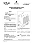
Section 61180212L2-5A
Issue 1, July 2002
CLEI Code: VAL230JA_ _
Total Access® 1500
Dual 4-Wire TO Access Module
Installation and Maintenance
CONTENTS
1. GENERAL .............................................................. 1
2. INSTALLATION ................................................... 2
3. PROVISIONING .................................................... 5
4. TEST FEATURES ................................................. 6
5. MAINTENANCE ................................................... 6
6. SPECIFICATIONS ................................................. 6
7. WARRANTY AND CUSTOMER SERVICE ........ 6
DUAL
TO
1180212L2
1
2
STATUS
FIGURES
Figure 1. Dual 4-Wire TO ........................................... 1
Figure 2. Dual 4-Wire TO Menu Tree ........................5
TABLES
Table 1. Compliance Codes ...................................... 2
Table 2. Time Slot and Wiring Interconnect ....... 3, 4
Table 3. Dual 4-Wire TO Options ........................... 5
Table 4. Front Panel LEDs ....................................... 5
Table 5. Specifications ............................................. 7
1. GENERAL
This practice provides installation and maintenance
procedures for the ADTRAN Total Access 1500 Dual
4-Wire Transmit Only (TO) Access Module. Figure 1
is an illustration of the Total Access 1500 Dual 4-Wire
TO.
Revision History
This is the initial release of this document. Future
revisions to this document will be explained in this
subsection.
General Description
The Dual 4-Wire TO Access Module is intended to be
deployed in the Total Access 1500 Chassis. The Dual
4-Wire TO provides for two individual 4-wire analog
interfaces between a VF transmission facility and the
Total Access 1500 Pulse Coded Modulation (PCM)
backplane. Each TO interface provides 4-wire
voice-grade (analog) data services with no signaling
associated with the circuit, or where signaling is
provided by in-band tones.
61180212L2-5A
Figure 1. Dual 4-Wire TO
Features
The features of the Dual 4-Wire TO (P/N 1180212L2)
include the following:
• Two independent DC-isolated 4-wire VF channel
interfaces
• Extended operating temperature range from
-40ºC to +65ºC
• TLP transmit input range of +5.0 to -16.0 dBm in
0.1 dB increments
• TLP receive output range of +8.5 to -9.5 dBm in
0.1 dB increments
• Supports configurations for Sink, Source or No
Sealing Current
• Provisioning by craft interface or Site Manager
• Digital Loopback and 1004 Hz Digital Reference
Signal (DRS) Tone Tests via craft port or Site
Manager
• NEBS Level 3 and UL 1950 compliant
Trademarks: Any
brand names
and product names
included
Section
61180212L2-5,
Issue
1 in this document are
trademarks, registered trademarks, or trade names of their respective holders.
1
This device complies with Part 15 of the FCC rules.
Operation is subject to the following two conditions:
2. INSTALLATION
1. This device may not cause harmful interference.
2. This device must accept any interference received,
including interference that may cause undesired
operation.
C A U T I O N !
SUBJECT TO ELECTROSTATIC DAMAGE
OR DECREASE IN RELIABILITY.
HANDLING PRECAUTIONS REQUIRED.
Remove the Total Access 1500 Dual 4-Wire TO from
the carton and visually ensure that damage has not
occurred during shipping or handling. If damage has
occurred, file a claim with the carrier, then contact
ADTRAN. Refer to Warranty and Customer Service
section of this practice.
The Dual 4-Wire TO inserts into any Access Module
slot (1 through 24) of the Total Access 1500 chassis.
To install the Dual 4-Wire TO access module, perform
the following steps:
1. Hold the unit by the front panel while supporting
the bottom side.
2. Align the card edges to the guide grooved for the
designated slot.
3. Insert the card until the edge connector seats
firmly into the backplane.
4. Push the ejector in place to ensure the unit is fully
seated.
Compliance
Table 1 shows the Compliance Codes for the Dual
4-Wire TO. The Dual 4-Wire TO complies with UL
1950, third edition. It is intended for installation in
restricted access locations only and in equipment with a
Type “B” or “E” installation code.
Changes or modifications not expressly approved by
ADTRAN could void the user’s authority to operate
this equipment.
Time Slot Assignments
For time slot assignments in the Dual T1 mode and in
the Quad T1 mode, refer to Table 2.
The Total Access 1500 platform can have multiple time
slots in the T1 data stream assigned to each physical
slot in the channel bank. The Total Access 1500 allows
craft selectable time slots using the electronic
provisioning interface. The system will automatically
map DS0s in the T1 as determined by the LIU
operational configuration. Manual mapping is available
via the LIU menu.
Connections
Four 50-pin male amphenol connectors on the rear of
the Total Access 1500 chassis provide the interconnect
wiring for each of the access module physical slots.
The Dual 4-Wire TO requires P1 (T/R) and P2 (T1/
R1) for the odd ports of each access module, while P3
(T/R) and P4 (T1/R1) for the even ports. See Table 2
for wiring interconnect details.
Table 1. Compliance Codes
Code
Power Code (PC)
Telecommunication Code (TC)
Installation Code (IC)
2
Input
Output
C
–
A
C
X
–
Section 61180212L2-5, Issue 1
61180212L2-5A
Table 2. Time Slot and Wiring Interconnect
Physical
Slot
1
2
3
4
5
6
7
8
9
10
11
12
61180212L2-5A
Associated T1/DSO
Port
Dual T1
Quad T1 (D4)
Quad T1 (D1D)
A1
A1
A1
1
A2
A2
A3
2
A3
A5
A9
1
A4
A6
A11
2
A5
A9
A17
1
A6
A10
A19
2
A7
A13
A2
1
A8
A14
A4
2
A9
A17
A10
1
A10
A18
A12
2
A11
A21
A18
1
A12
A22
A20
2
A13
B1
B1
1
A14
B2
B3
2
A15
B5
B9
1
A16
B6
B11
2
A17
B9
B17
1
A18
B10
B19
2
A19
B13
B2
1
A20
B14
B4
2
A21
B15
B10
1
A22
B16
B12
2
A23
B21
B18
1
A24
B22
B20
2
Section 61180212L2-5, Issue 1
Amphenol
Connection
Interconnect
Wiring
P1
P2
P3
P4
-
26/1
26/1
26/1
26/1
T/R
T1/R1
T/R
T1/R1
P1
P2
P3
P4
-
27/2
27/2
27/2
27/2
T/R
T1/R1
T/R
T1/R1
P1
P2
P3
P4
-
28/3
28/3
28/3
28/3
T/R
T1/R1
T/R
T1/R1
P1
P2
P3
P4
-
29/4
29/4
29/4
29/4
T/R
T1/R1
T/R
T1/R1
P1
P2
P3
P4
-
30/5
30/5
30/5
30/5
T/R
T1/R1
T/R
T1/R1
P1
P2
P3
P4
-
31/6
31/6
31/6
31/6
T/R
T1/R1
T/R
T1/R1
P1
P2
P3
P4
-
32/7
32/7
32/7
32/7
T/R
T1/R1
T/R
T1/R1
P1
P2
P3
P4
-
33/8
33/8
33/8
33/8
T/R
T1/R1
T/R
T1/R1
P1
P2
P3
P4
-
34/9
34/9
34/9
34/9
T/R
T1/R1
T/R
T1/R1
P1
P2
P3
P4
-
35/10
35/10
35/10
35/10
T/R
T1/R1
T/R
T1/R1
P1
P2
P3
P4
-
36/11
36/11
36/11
36/11
T/R
T1/R1
T/R
T1/R1
P1
P2
P3
P4
-
37/12
37/12
37/12
37/12
T/R
T1/R1
T/R
T1/R1
3
Table 2. Time Slot and Wiring Interconnect (continued)
Physical
Slot
13
14
15
16
17
18
19
20
21
22
23
24
4
Associated T1/DSO
Dual T1
Port
Amphenol
Connection
Interconnect
Wiring
P1 - 38/13
P2 - 38/13
P3 - 38/13
P4 - 38/13
T/R
T1/R1
T/R
T1/R1
P1 - 39/14
P2 - 39/14
P3 - 39/14
P4 - 39/14
T/R
T1/R1
T/R
T1/R1
P1 - 40/15
P2 - 40/15
P3 - 40/15
P4 - 40/15
T/R
T1/R1
T/R
T1/R1
P1 - 41/16
P2 - 41/16
P3 - 41/16
P4 - 41/16
T/R
T1/R1
T/R
T1/R1
P1 - 42/17
P2 - 42/17
P3 - 42/17
P4 - 42/17
T/R
T1/R1
T/R
T1/R1
P1 - 43/18
P2 - 43/18
P3 - 43/18
P4 - 43/18
T/R
T1/R1
T/R
T1/R1
P1 - 44/19
P2 - 44/19
P3 - 44/19
P4 - 44/19
T/R
T1/R1
T/R
T1/R1
P1 - 45/20
P2 - 45/20
P3 - 45/20
P4 - 45/20
T/R
T1/R1
T/R
T1/R1
P1 - 46/21
P2 - 46/21
P3 - 46/21
P4 - 46/21
T/R
T1/R1
T/R
T1/R1
P1 - 47/22
P2 - 47/22
P3 - 47/22
P4 - 47/22
T/R
T1/R1
T/R
T1/R1
P1 - 48/23
P2 - 48/23
P3 - 48/23
P4 - 48/23
T/R
T1/R1
T/R
T1/R1
P1 - 49/24
P2 - 49/24
P3 - 49/24
P4 - 49/24
T/R
T1/R1
T/R
T1/R1
Quad T1 (D4) Quad T1 (D1D)
B1
C1
C1
1
B2
C2
C3
2
B3
C5
C9
1
B4
C6
C11
2
B5
C9
C17
1
B6
C10
C19
2
B7
C13
C2
1
B8
C14
C4
2
B9
C17
C10
1
B10
C18
C12
2
B11
C21
C18
1
B12
C22
C20
2
B13
D1
D1
1
B14
D2
D3
2
B15
D5
D9
1
B16
D6
D11
2
B17
D9
D17
1
B18
D10
D19
2
B19
D13
D2
1
B20
D14
D4
2
B21
D15
D10
1
B22
D16
D12
2
B23
D21
D18
1
B24
D22
D20
2
Section 61180212L2-5, Issue 1
61180212L2-5A
3. PROVISIONING
There are no hardware options in the Dual 4-Wire TO
access module; its specific options can be provisioned
from the Site Manager or from a DB-9 VT100 craft
port on the Total Access 1500 SCU. The factory
default settings for the Dual 4-Wire TO access module
are noted in Bold Text in Table 3.
Menu Navigation
To traverse through the menus, select the desired entry
and press ENTER. To work backward in the menu
press the ESC (escape) key.
The menu tree in Figure 2 illustrates the path to every
provisioning, performance, and test access point in the
Total Access 1500 Dual FXS/DPO menu.
Password and User ID
Password protection is factory disabled. If password
protection is enabled, then the SCU will display the log
on screen, and a valid user ID and password are
required to access menus. The factory default user ID
is USER, and the default password is PASSWORD
both are in all capital letters. Both the user ID and
password are required.
Table 3. Dual 4-Wire TO Options
Function
Option
Description
Transmit TLP
-16.0 to +5.0 dBm (+0.0)
Transmit channel attenuation in 0.1 dB steps.
Receive TLP
-9.5 to +8.5 dBm (+0.0)
Receive channel attenuation in 0.1 dB steps.
Sealing Current
Mode
None
Sink
Source
Selects mode of sealing current operation.
1. Configuration
Unit Name
CLEI Code
Part Number
Software Revision
1. Circuit 1
1. Circuit
2. Circuit 2
2. Provisioning
2. Transmit TLP
3. Receive TLP
Enter Value
1. None
4. Sealing Current Mode
2. Sink
3. Source
3. Status
Circuit
Transmit TLP
1. Circuit 1
1. Circuit
2. Circuit 2
4. Test
2. 1004Hz Tone Test
Sealing Cur Mode
1. Off
Sealing Cur State
2. To Network
3. To Loop
Signal Bits Tx/Rx
4. To Loop and Network
3. Digital Network Loopback
Receive TLP
Digital Test
1. Off
2. On
Figure 2. Dual 4-Wire TO Menu Tree
61180212L2-5A
Section 61180212L2-5, Issue 1
5
Front Panel LEDs
The Total Access 1500 Dual 4-Wire TO has two front
panel LEDs that provide status information for each
interface. See Table 4 for LED indications.
4. TEST FEATURES
Initiated Tests
The Dual 4-Wire TO supports a Digital Network
Loopback and 1004 Hz Tone Tests for each port to
support circuit turnup and maintenance efforts. These
tests are initiated from the Total Access Site Manager
or the Total Access 1500 Local Craft Port on the SCU,
and are initiated on an individual port basis.
Digital Network Loopback Test
The Digital Network Loopback provides a loopback
path for the DS0 data from the network. Received
data of the selected port is latched in on the appropriate
receive time slot on the receive bus, and then placed on
the transmit bus in the appropriate port’s transmit time
slot.
1004 Hz Tone Test
The 1004 Hz Tone Test generates a 1004 Hz @
0 dBm Digital Reference Signal (DRS) tone, which is
used to send DRS signal to the loop, to the network, or
to both simultaneously.
6. SPECIFICATIONS
Specifications for the Dual 4-Wire TO are detailed in
Table 5.
7. WARRANTY AND CUSTOMER SERVICE
ADTRAN will replace or repair this product within ten
(10) years from the date of shipment if it does not meet
its published specifications or fails while in service.
Refer to ADTRAN U.S. and Canada Carrier
Networks Equipment Warranty, Document
60000087-10.
Contact Customer and Product Services (CAPS) prior
to returning equipment to ADTRAN.
For service, CAPS requests, or further information,
contact one of the following numbers:
ADTRAN Sales
Pricing/Availability
(800) 827-0807
ADTRAN Technical Support
Pre-sales Applications/Post-sales Technical Assistance
(800) 726-8663
Standard hours: Monday-Friday, 7 a.m. - 7 p.m. CST
Emergency hours: 7 days/week, 24 hours/day
5. MAINTENANCE
The Total Access 1500 Dual 4-Wire TO requires no
routine maintenance for normal operation.
ADTRAN Repair/CAPS
Return for Repair/Upgrade
(256) 963-8722
ADTRAN does not recommend that repairs be
performed in the field. Repair services may be obtained
by returning the defective unit to ADTRAN. Refer to
Warranty and Customer Service section for further
information.
Repair and Return Address
ADTRAN, Inc.
CAPS Department
901 Explorer Boulevard
Huntsville, Alabama 35806-2807
Table 4. Front Panel LEDs
Label
6
Condition
Description
1
Green
Yellow
Red
Port 1 is operating normally
Port 1 is in a menu controlled test
Port 1 failure has been detected
2
Green
Yellow
Red
Port 2 is operating normally
Port 2 is in a menu controlled test
Port 2 failure has been detected
Section 61180212L2-5, Issue 1
61180212L2-5A
Table 5. Specifications
Performance
Transmit TLP Range: +5.0 to -16 dBm in 0.1 dB increments
Receive TLP Range: +8.5 to -9.5 dBm in 0.1 dB increments
Frequency Response: ±0.25 dB, 300 to 3000 Hz
Echo Return Loss: ≥ 28 dB
Singing Return Loss: ≥ 20 dB
Longitudinal Balance: ≥ 58 dB @ 200 to 1 kHz; 53 dB @ 3 kHz
Idle Channel Noise: ≤ 23 dBrnC0
PCM Encoding/Decoding: µ-law
Power
Current Draw: 0.050 A maximum @ -48 V
Physical
Dimensions: 3.125 in. H x 0.62 in. W x 10.1 in. D
Weight: < 1 lb.
Environment
Operating Temperature (Standard): -40ºC to +65ºC
Storage Temperature: -40ºC to +85ºC
Relative Humidity: 95% maximum @ 50ºC, noncondensing
Heat Dissipation: 2.4 watts maximum
Compliance
UL 1950
NEBS Level 3
FCC 47CFR Part 15, Class A
Part Number
Total Access 1500 Dual 4-Wire Transmit Only Access
Module
61180212L2-5A
1180212L2
Section 61180212L2-5, Issue 1
7
8
Section 61180212L2-5, Issue 1
61180212L2-5A