1
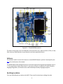
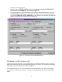
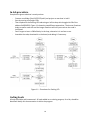
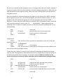
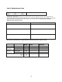
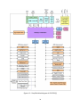
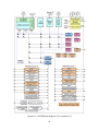
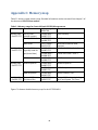
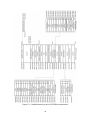
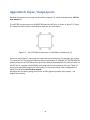
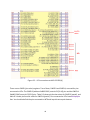
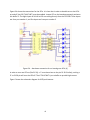
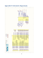
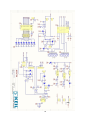
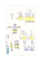
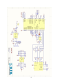
Figure D.4 shows the connections for the LEDs. It is clear that in order to be able to turn the LEDs
on and off, the IC9 (74LVC244T) must be enabled. Jumper LED on the board permanently activates
this buffer IC. The eight inputs of A1~A8 to IC9 are coming directly from the LPC1768. Three inputs
are from port number 1, and five inputs are from port number 2.
Figure D.4 – Hardware connection for on-board green LEDs [4]
In order to turn one LED on (like P1.28), a ‘1’ must be written to the pin P1.28. Similarly, writing a
‘0’ to P1.28 pin will turn the LED off. The IC 74LVC244T is just a buffer to provide high current.
Figure 5 shows the schematic diagram for INT0 push buttons.
47