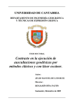
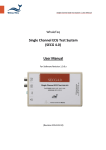
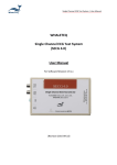
1
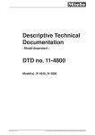
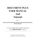
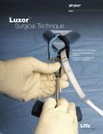
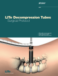
TransDiscalTM System for Disc Biacuplasty User Guide Baylis Medical Company, Inc. 15-August-2006 Version 2.0 © Baylis Medical Company, Inc. 2006 TransDiscal is a trademark of Baylis Medical Company 1. Table of Contents 1. 2. 3. 4. 5. 6. 7. 8. 9. 10. 11. 12. Table of Contents .................................................................................................. 2 Introduction............................................................................................................ 2 Physics of the TransDiscal System ....................................................................... 3 Technical Description of the Equipment.............................................................. 10 Patient Selection ................................................................................................. 12 Setup Instructions................................................................................................ 13 Placement Guidelines ......................................................................................... 19 Procedure Parameters ........................................................................................ 27 Generator Graphs during Treatment ................................................................... 29 Post-Procedural Care...................................................................................... 32 Troubleshooting............................................................................................... 41 References ...................................................................................................... 52 2. Introduction The TransDiscal System, in combination with the Baylis Pain Management GeneratorTD (PMG-TD), is indicated for the coagulation and decompression of intervertebral disc material to treat symptomatic patients with contained herniated discs. The procedure is called intervertebral disc biacuplasty and the equipment used for the procedure is called the TransDiscal System. In this procedure two TransDiscal Introducers are placed within the disc with a bilateral approach. A TransDiscal Probe with an electrode, a.k.a. active tip, on the end is inserted through each introducer and into contralateral sides of the posterior intervertebral disc. Radiofrequency (RF) energy is delivered from and concentrated around and between the two electrodes. The electrodes are internally-cooled with circulating water. RF energy heats the tissue and the cooling moderates the heating in close proximity to the electrodes. This combination creates an ideal heating profile across the posterior disc without excessive heating. A physician using this equipment must be familiar with lumbar spine anatomy, imageguided spine procedures and intervertebral disc pathology. Important Message This guide does not replace the information in the Instructions for Use provided with the components of the TransDiscal System. The Instructions for Use includes important information such as warnings, precautions, contraindications, and trouble shooting. The Instructions for Use for each component must be read prior to use. Page 2 of 53 3. Physics of the TransDiscal System Overview This section briefly explains how the TransDiscal System heats disc tissue. In this section you will learn: • • • • The reason why high frequency alternating current is used to heat tissue. The reason why a bipolar electrode set-up is used during the procedure. The reason why the TransDiscal Probes are internally-cooled. How the physics of the complete TransDiscal System work together to thermally treat the intervertebral disc. Direct Current & Alternate Current Electric current refers to the amount of charge that passes through a surface per measure of time. At an atomic level, current is the flow of electrons. A current that moves in the same direction around a circuit is referred to as Direct Current (DC). A current whose direction alternates continuously back and forth is referred to as Alternating Current (AC) (see Figure 1). The number of times that the current alternates back and forth in a second is known as frequency. Frequency is measured in Hertz. For example 60 Hertz means that the current alternates back and forth 60 times per second. Current Current 0 Time Direct Current (DC) 0 Time Alternate Current (AC) Figure 1: Direct Current (DC) and Alternate Current (AC) signal amplitudes. Resistive Heating with DC In order to understand resistive heating, you must first understand conductance. Electrical conductance is the property of a material that determines the ability of current to flow through it and is based on the availability of loose electrons in the material. Resistance is the opposite of conductance. Copper wire, for instance has high conductance and is a good conductor while rubber has low conductance and is a very poor conductor. Since rubber is a poor conductor, this means that it is a good resistor. In a resistor, as current passes through the material, energy is used. The harder it is to pass current through a material, due to lower conductance, the more energy is used. The energy that is used does not disappear but is converted to a different form of Page 3 of 53 energy, often in the form of heat. The conversion of electrical energy to thermal energy by passing current through a material with resistance is called resistive heating. A good example of resistive heating is an electric toaster. The metal filament in the toaster is made of nickel and chromium, which has an ideal resistance to convert electricity to heat. Biological tissue is not a very good conductor when using direct current. Resistive heat can be generated but the flow of current cannot be controlled easily and it can damage the cells. Using direct current to heat tissue may produce unpredictable tissue temperatures and irregular shaped lesions. Excessive temperatures would lead to burning of tissue, gas formation, and uncontrolled destruction of tissue1. Ionic Heating with AC Another way electrical energy is converted to heat in tissue is by ionic heating. To overcome the drawback of direct current, use of alternating current for medical applications was pioneered by Cushing and Bovie in the 1920s, originally for hemostasis2. Later in the 1950s, Aranow and Cosman deployed alternating current for creating neural lesions3. Alternating current conducts through tissue with less resistance and more control than direct current. The greater the alternating current frequency, the greater the conductance4. Alternating current causes the charged molecules, or ions, in the tissue to follow the directional variation of the alternating current resulting in molecular vibration. The molecular vibration produces heat due to frictional forces5,6. This effect is called ionic heating. The body is a complex system that uses electric current for a wide range of functions from regulating a heart beat to sending the sense of touch from a finger to the brain. If alternating current is applied to the body using frequencies similar to those used by the body, it can interfere with physiological functions causing unwanted effects. This is avoided by using a frequency beyond those used by the body. Alternating current with a very high frequency, in the order of 500 kHz, does not affect physiological functions. RF Generators in the Market Today Today, modern AC generators use a frequency between 400 and 600 kilohertz which is in the radiofrequency (RF) range and are generally referred to as RF generators. RF generators are now equipped with automatic temperature control and impedance monitoring. Temperature control allows for effective lesion formation whereas impedance monitoring detects changes in tissue resistance to electric current. Impedance monitoring also aids in electrode placement because impedance varies between different tissues 1,5. Monopolar and Bipolar Electrode Systems Monopolar System Physics In medical applications RF current is delivered to tissue by an electrode usually on the end of a probe or insulated cannula. Ionic heating of tissue is a function of the current density, or current per unit area. RF current flows out of the electrode radially, and as a result, current density progressively decreases away from the electrode7. This is illustrated in Figure 2, where a circle represents an electrode, and arrows represent the current flowing radially from the electrode. The current, shown by the arrows is denser in areas closer to the electrode. Consequently, ionic heating is greatest at the proximity of the electrode and decreases with increasing distance. RF devices often contain temperature sensors. Note that the electrode itself does not heat up. Instead the tissue Page 4 of 53 heats from ionic heating and the heat conducts back to the electrode1, where the sensor indicates the tissue temperature local to the electrode. This decreasing gradient of current density limits the size of the heat lesion that can be produced. With a constant power a heat lesion will only grow to a limited size because the amount of heat created will come to equilibrium with the heat removed by the surrounding tissue and blood flow. Figure 2: Current density, represented by arrows, around an electrode, represented by the circle. Note how the tail ends of the arrows are more concentrated at the electrode and less dense as the arrows radiate away from the electrode. A way to increase the volume of tissue heated using RF is to increase the power. However, increasing power also has its limitations. It has been demonstrated that tissue impedance (the measurement of tissue resistance to alternating current) decreases as the temperature increases, up to 60 to 70°C; further increase in temperature leads to a rapid increase in tissue impedance8. As tissue impedance increases at high temperatures the further flow of current becomes more difficult and harder to control. The current emanating from the electrode, or pole, in Figure 2 travels through the body completing the circuit at another electrode, or pole. The second electrode, also referred to as a return or passive electrode, determines if the system is a monopolar or bipolar system. Monopolar RF systems deliver current between an active electrode, with a small surface area, and a passive electrode, with a large surface area. Although two poles are present, the term monopolar is used to describe this configuration because only the active electrode (with its small surface area and corresponding high current density) creates a substantial ionic heating effect (Figure 3a). The same amount of current that emanates from the active electrode is dispersed over the much larger surface area of the passive electrode, and current density is very low. This means that ionic heating is not produced around the passive electrode. Bipolar System Physics A bipolar RF system contains two electrodes that have the same surface area. The same amount of current flows through both electrodes, and since the surface area is the same, the current density is the same (Figure 3b). This results in the same ionic heating around each pole. A given amount of current in a bipolar system can heat twice the volume of tissue as the same amount of current in a monopolar system. Page 5 of 53 Figure 3: A representation of monopolar and bipolar systems for RF heating. Ionic heating is limited by decreasing current density and increasing tissue impedance. These effects mean that monopolar systems are good for creating small lesions but are of limited value when attempting to create larger lesions. In general, monopolar systems produce focal ellipsoid lesions less than 1.6 cm in diameter9. For larger lesions, multiple usage of the monopolar RF is inefficient and inconsistent10. Bipolar systems can heat twice the volume of monopolar systems. Furthermore, if the two electrodes are sufficiently close to one another, a “strip” lesion is formed between the two electrodes, as shown in Figure 4. Simultaneous RF ablation using two electrodes in close proximity has been shown to produce a larger lesion compared with two sequential monopolar ablations using single electrodes11. This effect is created because the RF current is concentrated between the electrodes. Page 6 of 53 Figure 4: Creating a strip lesion. A) Two single lesions are formed if the electrodes are too far apart. B) A “strip” lesion that is larger than the sum of the two single lesions can be formed if the electrodes are close enough to each other. Internally-Cooled RF Systems Another means of increasing the volume of the lesion is by using internally-cooled RF electrodes. This technique was first proposed by Wittkamp in 198812. The hollow lumens of internally-water cooled probes permit continuous cooling of the electrode with a fluid. Internally-cooled RF electrodes act as heat sinks that remove heat from tissue adjacent to the electrode. Consequently, time, duration, or power deposition can be increased during the procedure without causing high impedance and tissue charring around the electrodes13. As a result, internally-cooled electrodes can produce much larger lesions compared to non-cooled electrodes14. Furthermore, the tissue in proximity to the electrode does not need to be as hot in order to reach target temperatures at greater distances away from the electrode (Figure 5). Water temperature, in the range of 5°C to 25°C when used for cooled RF, has been shown to not significantly affect lesion size in ex vivo hepatic ablations15. Alternatively, increasing flow rate of the coolant has been demonstrated to significantly affect lesion size16. The combined benefits of cooled RF with a bipolar system allow a “strip” lesion to be created when the electrodes are at even greater distances apart. Page 7 of 53 Figure 5: Temperature distribution of non-cooled and cooled RF electrodes. Benefits of the TransDiscal System The Baylis Medical TransDiscal System is an internally-cooled, bipolar RF system for thermal treatment of the intervertebral disc. The aim of the TransDiscal System is to generate reproducible thermal lesions in the posterior and posterolateral annulus. The system is a cooled bipolar radiofrequency system which combines the principles described above to heat a large volume of the disc. RF Energy Controls Lesion Size Page 8 of 53 The TransDiscal System uses radiofrequency (RF) energy to heat the tissue. Consequently, lesions can be produced accurately, predictably, and safely. Bipolar Arrangement Creates a Large Lesion The TransDiscal System uses a pair of electrodes in a bipolar arrangement. The pair of electrodes concentrates current between the two electrodes and creates a “strip” lesion covering the posterior and posterolateral annulus fibrosus. Other minimally invasive treatments require precise catheter placement to heat the targeted area of the disc. Internally-Cooled for Greater Power Applications The TransDiscal electrodes are internally-cooled which allows for greater power to be used. The water-cooling of the electrodes also prevents charring of tissue adjacent to the electrode. The greater power dissipation also contributes to the creation of a larger “strip” lesion between the electrodes. Other minimally invasive treatments create very high tissue temperatures adjacent to the electrode, which may result in charring of tissue. Tissue charring can result in an irregularly shaped lesion, and increase tissue impedances, preventing power to be dispersed farther into the tissue. Temperature Control Temperature sensors at the electrode tips allow the RF generator to control the power delivery and the rate of internal electrode cooling. The temperatures at the electrode tips are reflective of the surface of the cooled electrodes, and not the maximum lesion temperature. Safe & Easy Placement Placement of the TransDiscal probes is straight-forward and results in minimal disturbance to the disc tissue. Other minimally invasive treatments use a long flexible catheter to treat the entire posterior area. The flexible catheter may take additional time to position correctly, and create extraneous channels within the disc. Impedance Monitoring for Accurate Placement The TransDiscal system is equipped with impedance monitoring that allows for accurate placement, given that impedance varies between different tissue types. Once the TransDiscal System introducer penetrates the annulus fibrosus of the disc, the impedance decreases. If the TransDiscal introducer enters the nucleus pulposus, the impedance decreases further. Thus, impedance monitoring, in addition to fluoroscopic imaging and tactile feel, allow for accurate placement of the electrodes. Other minimally invasive treatments do not offer this additional guide during placement. TransDiscal System Summary The TransDiscal System creates large reproducible lesions in the posterior and posterolateral annulus fibrosus by using the advantages of: • Temperature controlled radiofrequency energy application • Bipolar placement • Internally-cooled electrodes • Impedance monitoring Page 9 of 53 4. Technical Description of the Equipment Overview In this section you are going to learn about all of the components of the TransDiscal System. You will learn the function of each device and the relationship of the device within the system. Baylis Pain Management Generator (Model PMG-TD) Important features: • • • A software-based, computerized radiofrequency generator. Several safety features are incorporated into the control algorithm. For example, the generator can detect broken or improperly set-up equipment and give appropriate error messages. It is designed to power and control the pump unit, and provide automatically controlled parameters designed for the procedure. Pain Management Pump Unit (Model TDA-PPU-1) Important features: • • • The pump unit includes two peristaltic pump heads It circulates sterile water through the TransDiscal Probes. This is achieved via two closed-loop fluid circuits. Each closedloop fluid circuit includes a Pain Management Tube Kit and a TransDiscal Probe. The TransDiscal Pump comes with a connector cable which connects it to the generator (PMG-TD) for power and speed control. Pain Management TransDiscal Y-Connecting Cable (Model TDX-YTSW-TDP) Important features: • • • • Used to connect two TransDiscal Probes to the generator. Transmits RF energy from the generator to the probes. Transmits signals from the temperature sensors in the probes to the generator. Connects an introducer to the generator for impedance guided placement. Page 10 of 53 TransDiscal Probe (Model TDP-17-150-6) Important features: • • • • • Two probes are required for a typical procedure. One probe delivers RF energy to the surrounding tissue and the second probe collects RF energy, acting as the return electrode. The current density surrounding both probes is equal. Sterile water is circulated internally within the electrode during the procedure, which cools the electrode. The sterile water is contained and does not contact patient tissue. Each probe has two temperature sensors, one at the distal end of the electrode and the other a few millimeters away. The two temperature sensors measure temperature and provide control of RF energy delivery throughout the procedure. Each probe includes a 4’ cable and tubing extension to reach out of the sterile field. TransDiscal Introducer (Model TDIB-17-150) Important features: • • • Two introducers are required for a procedure. An introducer is comprised of a fully-insulated cannula and a sharp trocar-tipped stylet. Model TDI-17-150 includes a cable attached to the stylet which allows impedance monitoring by the generator which can be used as a placement aid. The 17-gauge introducer allows for accurate placement of the probe. Pain Management Tube Kit (Model TDA-TBK-1) Important features: • • • Two tube kits are required for a procedure. Each is used for circulation of sterile water through the TransDiscal Probes for the purpose of cooling the electrodes. The Pain Management Pump Unit pumps water through the tube kits. The Tube Kit comprises medical grade tubing and a burette that holds sterile water. Page 11 of 53 5. Patient Selection Candidates for disc biacuplasty using the TransDiscal System must have a history of chronic back pain originating from the disc for greater than 6 months and meet the following selection criteria. Inclusion Criteria Patients must meet all of the inclusion criteria. • Criteria for discogenic pain satisfied, viz. o Predominant axial / mechanical pain. o Demonstration of positive concordant pain of intensity >6/10 during provocative lumbar discography at 1 or 2 disc levels at low pressures (<50 psi) with negative control disc at one and preferably two adjacent levels and sham pressurization. o Physical examination. • Chronic pain (>6 months). • Age greater than 18 years. • At least 50% preserved disc height. • Failure to achieve adequate improvement with comprehensive non-operative treatment including: non-steroidal anti-inflammatory, physical therapy, and fluoroscopically guided epidural steroid injection in and around area of pathology. • Other possible causes of low back pain have been ruled out eg. failure to obtain prolonged improvement (> 14 days) from facet injections, sacroiliac joint injections or RF rhizotomies. Exclusion Criteria Patients will be excluded if they meet any of the following criteria: • Neurological deficit. • Intervertebral disc herniations greater than 4mm. • Extruded/sequestered intervertebral disc herniations. • Spinal pathology that may impede recovery such as spina bifida occulta, spondylolisthesis at the painful segmental level, or scoliosis. • Moderate to severe foraminal or central canal stenosis. • Pregnancy. • Existing endplate damage or Schmorl’s nodes. • Greater than grade 4 annular tear (Modified Dallas Grading). • Systemic infection or localized infection at the anticipated introducer entry site. • History of coagulopathy or unexplained bleeding. Relative Contraindications • • • • • Body Mass Index greater than 29.9 (obese). Irreversible psychological barriers to recovery. Prior lumbar spine surgery. Radiculopathy. Immunosuppressed (eg. AIDS, cancer, diabetes, other surgery within last 3 months). Page 12 of 53 6. Setup Instructions Overview The following section outlines the procedure for setting up the TransDiscal System. We have provided two set-up guides: • Quick Start Equipment Set-Up designed for users who have previously handled the equipment. • Detailed Equipment Set-Up designed for users who are using the system for the first time. Equipment Set-Up Diagram The TransDiscal System consists of: Reusable Equipment: 1. 2. 3. 4. Pain Management Generator-TD Pain Management Pump Unit Pump Connecting Cable TransDiscal Y-Connecting Cable Disposable Kit: 5. two Pain Management Tube Kits 6. two TransDiscal Probes: 7. two TransDiscal Introducers: Quick Start Equipment Set-Up 1. Connect the Generator to the Pain Management Pump Unit 2. Plug in the Generator and turn it on 3. Insert Pain Management Tube Kits into the Pain Management Pump Unit 4. Fill the burettes with sterile water 5. (Optional) Connect the introducers to the generator for impedance guided placement 6. Place the introducers and probes in the patient. 7. Connect probes to Pain Management Tube Kits 8. Connect the probes to the Y-Connecting Cable Figure 6: TransDiscal set up Page 13 of 53 Detailed Equipment Set-Up 1. Connect the Generator to the Pain Management Pump Unit • Connect the male connector of the Pain Management Pump Connector Cable to the generator. • Connect the female connector of the Pain Management Pump Connector Cable to the Pump Unit. • Push the connectors as far in as possible, and then tighten by turning the collar clockwise. 2. Plug in the Generator • Plug the power cord into the Pain Management Generator, and connect the generator directly to a grounded receptacle. • Turn the generator on. Page 14 of 53 3. Insert Tube Kits into the Pain Management Pump Unit • Remove the Pain Management Tube Kits from the sterile package. • Put the burettes into the Pump Unit’s burette holders. • Open the pump head lids and thread the thicker tubing from the bottom of the burette into the pump head tube holders. • Ensure that the tubing is properly placed between the notches. Improper positioning of the tubing can pinch the tube and restrict the water flow. • Close the lid in order to hold the tubing in place. Leave the luer lock caps on the tubing until you are ready to connect the probes so the inner pathway of the tube kit remains sterile. Burette Burette Holder Pump Head Lid Notches Pump Head Thick tubing 4. Fill the burettes with sterile water • Remove the cap of the burette. • Using a sterile syringe, fill the burettes with 70 ml of sterile water or saline at room temperature. • Repeat with the second burette. Page 15 of 53 5. Connect the TransDiscal Introducers to the generator for impedance guided placement (optional) • The TransDiscal Introducers (model TDIB-17-150 sold separately) can be placed using optional Impedance Guided Placement as follows: Connect the 14-pin connector of the Y-Connecting Cable to the generator. Connect the first introducer to the branch of the Y-Connecting Cable labeled “Side A”. Plug a grounding pad in to the generator and attach the pad to the patient. Enter TransDiscal placement mode and the impedance will be displayed and a related tone will sound. Once the first introducer is placed disconnect it from the Y-connecting cable and repeat for the other introducer using only “Side A” of the cable. 6. Place the introducers and probes in the patient • Prepare the patient and place the TransDiscal Introducers and Probes in the disc – See Section 7 for Placement Guidelines. 7. Connect probes to Pain Management Tube Kits • Pass the tubing and electrical connections on the probe out of the sterile field. • Remove the caps from the two luer locks on each of the TransDiscal Probes and the Tube Kits. Connect the luer locks snugly. It does not matter which probe is connected to each tube kit. Maintain sterility of the tubing’s inner pathway so in case water is accidentally spilled in the sterile field, sterility will not be compromised. Luer Lock Cap Luer Lock Page 16 of 53 8. Connect the probes to the Y-Connecting Cable • Connect the male connectors on the TransDiscal Probes to the female connectors on the Y-Connecting Cable. • Connect the Y-Connecting Cable to the generator if you have not already done so for impedance guided placement. It does not matter which side of the YConnecting Cable each probe is connected to. Now the equipment set-up is complete! Page 17 of 53 Schematic Diagrams of the TransDiscal System Set-Up Figure 7: Schematic diagram showing setup for treatment mode. PAIN MANAGEMENT TRANSDISCAL Y-CONNECTING CABLE Figure 8: Schematic showing setup for placement mode. Page 18 of 53 7. Placement Guidelines Overview This section describes the positioning of the introducers and probes within the disc. In this section you will learn: • • • The general safety guidelines for placement Brief lumbar anatomy with fluoroscopic and photographic images Step-by-step placement technique General Safety Guidelines For safe and effective tissue heating and safe anatomical access abide by the following guidelines: • The electrodes should be placed such that the beginning of the electrode, indicated by a dark band on fluoroscopy, is at least 5 mm from the disc’s outer surface. Proper depth can be assured if the distal end of the introducer is at the edge of the disc and the probe is fully inserted into the introducer. • The angle of approach should be between 20° to 30° from the sagittal plane. The same angle as the pedicle is appropriate and allows the pedicle to be used as a landmark. If a smaller angle is used the electrodes may end up too close to the lateral surface of the disc. If a larger angle is used the electrodes may be very close together and too far from the lateral edges of the disc and heating of the lateral regions may be insufficient. • The introducer should pass lateral to the superior articular process but it should not make contact. This is to prevent injury of the zygapophaseal joint. • The electrodes should be placed at approximately the center of the disc height. Ensuring the electrode is far away from either endplate increases the safety of the procedure. With the probe fully inserted into the introducer, the distal opening of the introducer should be at the edge of the disc to ensure proper depth in to the annulus. The introducer passes lateral to the SAP without injuring the z-joint. 20-30° Figure 9: TransDiscal Probe placement guidelines. Page 19 of 53 Lumbar Anatomy Fluoroscopic Image : This is an oblique view of a lumbar spine showing an outline of the ‘’Scotty Dog’’ and some of the boney landmarks. Photograph: Compare the above image with this photograph of a spine model. This photograph is taken at the same angle as the fluoroscopic image and also has an outline of the ‘’Scotty Dog’’. Page 20 of 53 Placement Technique A technique for placing introducers and TransDiscal Probes in the annulus, as suggested by Dr. William Whyte, is described below. 1. Ascertain the disc level to be treated by locating the T12 vertebra with ribs and count the levels moving caudal. Obtain a true AP view of the disc to be treated. This is confirmed by flat endplates and equal distance between the pedicles and the spinous process. 2. While maintaining the sagittal angle, rotate the c-arm obliquely until it is parallel to the pedicle. This angle is approximately 3040° and shows a clear image of the Scotty dog. The Superior Articular Process (SAP) or the ear of the Scotty dog should be seen superimposed over the disc with approximately 1/4 to 1/3 the disc width lateral to the SAP. A path to the entry target of the disc can be seen lateral to the SAP. SAP Page 21 of 53 A note on incorrect oblique angle: If the oblique angle is too large: If the SAP is at more than 1/3 of the disc width, the oblique angle will be too large and the probes might be placed too far from the lateral edges of the disc. A fluoroscopic image of a lumbar spine with the C-arm at approximately 45°. The SAP appears about ½ the disc width. If the oblique angle is too large, the resulting placement of introducers will be too medial and the lateral portions of the disc may not be heated. If the oblique angle is too small: If the SAP is at less than 1/4 of the disc width the oblique angle is not enough and the probes may be placed too close to the lateral edges of the disc. A fluoroscopy image of a lumbar spine with the C-arm at approximately 10°. The SAP appears about 1/5 the disc width. If the oblique angle is too small, the resulting placement of introducers will be too lateral and the tissue lateral to the disc may be heated. Page 22 of 53 3. Under fluoroscopy place a radiopaque tool, such as Kelly’s clamps, on the surface of the skin directly over the entry target of the disc. 4. Mark the entry point on the skin with a sterile marker. 5. Inject local anesthetic along the introducer tract. Avoid anesthetizing the area around the spinal nerve so the patient can respond to any sensations indicating potential injury to the nerve. 6. Maintain the oblique view and advance the introducer to the disc. This can be done by using live fluoroscopy or by using multiple shots of X-ray. When using live fluoroscopy hold the introducer by the hub with clamps and gently advance the introducer to the annulus fibrosus aiming for the middle of the disc height. When using multiple shots of Xray advance the introducer a little at a time until the target is reached. Page 23 of 53 7. Because the annulus is a harder tissue than the soft muscles, the annulus can be felt as the introducer makes contact. Anchor the introducer within the disc. 8. Verify that the introducer is anchored in the disc by using live fluoroscopy while gently flicking the introducer. The introducer can be seen moving in soft tissue but the tip will be held in place in the annulus. B A B A 9. Advance the introducer approximately 1 cm into the disc. The depth markings on the introducer are spaced apart by 1 cm. In an AP view the tip of the introducer is advanced from point A to point B. Notice the position of lines A and B in relation to the pedicles. Page 24 of 53 10. Confirm the position of the introducer in the disc with a lateral view. Depth adjustments can be made later once the probe is inserted. At this time the introducer should be in the disc approximately 1 cm. 11. Place the other introducer in the contralateral side of the disc using the same technique. 12. Remove the stylet from an introducer and insert a probe. Keep the stylet in the sterile field incase the introducer needs to be repositioned. Never reposition an introducer without the stylet inserted. A hollow introducer is not sharp enough or strong enough and will break. The probe will protrude from the introducer by 1 cm when fully inserted. While keeping the probe fully inserted in the introducer pull them back so the distal tip of the introducer is near the edge of the disc and the probe is about 1 cm into the disc. This lateral view shows an introducer that is in the left side of the disc and a probe that is inserted into the introducer on the right side. Page 25 of 53 13. Remove the stylet from the other introducer and insert the second probe. 14. Make slight depth adjustments to both probes in a lateral view. Ideally, the distal tip of the probe is no further than the center of the disc. The radiopaque band denotes the beginning of the electrode and it must be within the disc space. This lateral view shows two probes, one in each introducer. In a true lateral view the probes are almost superimposed on one another. The C-arm is swiveled slightly to reveal both probes. 15. Check the placement on an AP view. Ideally, the distal tips of the probes are inserted to medial edges of the pedicles. The radiopaque bands and the rest of the electrode must be within the disc space. Page 26 of 53 8. Procedure Parameters Overview This section describes the parameters used to control the heating profile during the procedure. In this section you will learn: • • • What the modifiable parameters are How the parameters affect the heating Suggested parameters to use Parameters used to create heating profile The parameters available to control the heating profile are: Ramp Rate Set Temperature Time There are temperature sensors in the TransDiscal Probes. The generator will automatically deliver the required power to raise the temperature of the probes according to the heating profile which is determined by the parameters. At the beginning of the procedure the temperature is lower than body temperature because the pumps are running and cooling has begun. The probe temperature will increase at the Ramp Rate until it reaches the Set Temperature. The temperature will remain at the Set Temperature until the Time is complete. Page 27 of 53 Effect of Parameters Ramp Rate is the rate of increase in temperature (degrees Celsius) of the probe electrodes per minute. A slower Ramp Rate results in better control of heating, larger volumes of heated tissue, and more consistent temperature through the volume. A faster Ramp Rate results in shorter procedure time. In conventional non-cooled RF procedures such as a z-joint rhizotomy, ramp rate is usually about 15 seconds. This rate is much faster that what is needed with the TransDiscal system. It must be understood that a slower Ramp Rate is required when heating a large volume of tissue. Ramp Rate can only be changed in Advanced Settings of the generator. Set Temperature is the maximum temperature of the probe’s electrode surface. The temperature will increase at the Ramp Rate until it reaches the Set Temperature which is then maintained. Due to the cooling of the electrodes, the Set Temperature will be 1015° Celsius lower than the tissue a few millimeters from the electrode. The level of the Set Temperature in combination with the Ramp Rate and Time will affect the temperature throughout the tissue. Set Temperature can be changed at any time before or during the RF delivery. Time is the duration of radiofrequency energy delivery, including the temperature ramp up and plateau. A longer Time will allow a greater volume of tissue to be heated until thermal equilibrium is reached The optimum Time is long enough for adequate volume heating without excessive procedure time. Time can be changed at any time before or during the RF delivery. Suggested Parameters The suggested parameters used for treating a patient with the TransDiscal System are: Set Temperature = 45 ºC Ramp Rate = 2.0 ºC/min Time = 15 minutes These parameters were tested and scrutinized through a series of cadaver experiments. The experiments were designed to map temperatures in the disc and in the surrounding neural structures to ensure that heat was applied in a manner suitable for both efficacy and safety during treatment. For practical use, set the Advanced Settings on the generator as follows: Peripheral Disc Warning Temp = 33°C Ramp Rate: 2°C/min Show Peripheral Disc Temp = MAX Graph Power = YES Number of Probes = 2 Page 28 of 53 9. Generator Graphs during Treatment Overview This section shows images of generator screens to explain what a typical good procedure looks like compared to an abnormal procedure. In this section you will learn: • • Appearance of a typical procedure graph. Appearance of an abnormal procedure graph. The figures in this section represent screens of a Baylis Pain Management Generator (Model PMG-115-TD and PMG-230-TD, V2.0 to 2.1). Refer to the generator’s user manual for complete details. The graph on the generator shows the maximum of the two electrode temperatures (“TRANSDISCAL TEMP” in yellow), the maximum of the two peripheral temperatures (“PERIPHERAL DISC TEMP” in white), and the power (“POWER” in magenta). An ideal procedure graph, as shown in Figure 10, has fairly smooth lines with the TRANSDISCAL TEMP increasing more than the PERIPHERAL TEMP. This indicates that the temperature in the disc is increasing more than at the edge of the disc. The POWER is also a smooth line increasing to a plateau of about 5 to 7 watts. Figure 10: Generator graph of an ideal procedure. Page 29 of 53 The graph in Figure 11 is similar to the ideal graph except there is a small blip in the three lines at about 7minutes. This is commonly seen if the patient moves to get more comfortable or coughs. It may also be seen if the probes are bumped or moved. This is likely not a problem but it is a good idea to check the lateral and AP fluoroscopy views to make sure the probes are still in a desirable position in the disc. Figure 11: Generator graph showing a small blip is okay. Page 30 of 53 An example of a graph that indicates a poor procedure is shown in Figure 12. The PERIPHERAL TEMP is increasing faster than the TRANSDISCAL TEMP and the lines are not smooth but jagged. This indicates that the edge of the disc is heating up more than the inside of the disc. There may be a heat sink in the disc such as a severely degenerated disc containing blood. The power line is also jagged and is increasing to 12 watts in only two minutes. Stop the procedure if this scenario is seen. Figure 12: Generator graph of a poor procedure. Page 31 of 53 10. Post-Procedural Care Overview This section discusses what the patient should do after the procedure. In this section you will learn: • • • Patient discharge instructions. Activity guidelines. Physical therapy. The patient’s physical activity and care after their procedure is crucial to their recovery. A patient who has had chronic low back pain for some time will have weak back muscles and incorrect habits of back care, such as posture and lifting. The patient will need to gradually increase the strength of their stabilizing muscles and learn proper posture. Although pain may be greatly diminished or eliminated after the procedure, the patient must gradually increase activity and strength to allow muscles to develop properly, allow for the disc to recover from the procedure, and avoid injuring the disc or straining back muscles. The patient will be discharged from the clinic and instructed to avoid strenuous activity for a period of six weeks. A brace is necessary for 6-8 weeks and physical activity must be increased gradually. A recommended therapy program, provided by Physical Therapist Marleen Dunfee, is included. The program is directed at gradually increasing activity and practicing proper mechanics of posture and lifting. This physical therapy program is recommended as a guideline and the physician can make modifications at their discretion according to the patient’s physical condition and ability. Page 32 of 53 The following instructions can be given to the patient at the discretion of the physician. Discharge instructions for the day of the procedure Do not drive or operate machinery Do not engage in any strenuous activity Wear the brace all the time for 6-8 weeks except when showering or in bed. Showering is permitted, avoid soaking in the bathtub Eat a regular diet You may remove bandages the following day You may use an ice pack today and warm moist heat tomorrow if you experience discomfort when the local anesthetic wears off. Seek immediate medical attention if…. If you experience severe headache or severe pain at the injection site with swelling and redness. If your pain increases or if you experience fever or chills If you experience shortness of breath or chest pain Activity guidelines after the procedure Rest for 1-3 days after the procedure in a comfortable position (i.e. lying down or reclining). Limit sitting or walking to 10-20 minutes at a time. Return to work If your work is sedentary you may return in roughly one week. For other jobs, especially physically demanding jobs, the decision will be made by your physician. Driving Do not drive for the first 1-5 days, and driving should be limited to 20-30 minutes for the first 6 weeks. Make sure your vehicle has good lumbar support - you may need a pillow. As a passenger, recline the seat and try to limit driving duration to less than 45 minutes for the first 6 weeks. It is okay to recline or lie down in the back seat and be driven home the day of your procedure. Sitting Limit to 30-45 minutes at a time for the first 6 weeks in a chair with good support. Avoid sitting on soft couches or chairs. Stand and walk about for short breaks between sitting periods. Page 33 of 53 Home Exercise Program (0-6 weeks) Page 34 of 53 procedure. Be aware of your sitting restrictions Page 35 of 53 Week 1-6 Page 36 of 53 Page 37 of 53 Week 6-8 Page 38 of 53 Page 39 of 53 Home exercise program provided by Physical Therapist Marleen Dunfee Page 40 of 53 11. Troubleshooting Overview In this section you will learn how to trouble-shoot the TransDiscal System. In this section you will: • • Learn how to identify potential problems with system components Become familiar with the Generator Error and Fault Codes that may appear during a TransDiscal procedure Trouble-Shooting TransDiscal RF System Components Each component of the TransDiscal System, excluding the BMC RF Generator, has a trouble-shooting table in their Instructions for Use to assist the user in diagnosing potential problems. The BMC RF Generator has a section dedicated to the Error and Fault codes that may be seen during a TransDiscal procedure. Page 41 of 53 TransDiscal RF System Component Trouble-shooting Troubleshooting during equipment set up Problem Possible Device Damage to the TransDiscal Introducer, packaging of a sterile TransDiscal Probe and Pain device Management Tube Kit Obvious visual damage to any product. Electrical connectors do not connect TransDiscal Y-Connecting Cable, Pain Management Pump Unit, TransDiscal Probes, TransDiscal Introducers, Pain Management Tube Kits TransDiscal Probe and TransDiscal Y-Connecting Cable Trouble-Shooting Actions Visually inspect the packaging before use. The sterile pouch should not have any holes. Discard the device if packaging has been compromised. Visually inspect the products for any damage. Look for damage such as cuts, cracks, breaks, and bends. Do not use damaged equipment. Check that the connector's keys are lined up in the proper orientation. Turn the connector until it slides in the mating connector. Ensure that the connectors are clean and unobstructed. Fluid connectors do not connect The Pump will not accept the Tube Kit tubing The float ball is stuck on bottom port of the burette when water is injected. Tube Kit breaks, is leaking or is occluded. Pain Management Tube Kit Check that the connectors being connected have the same number of pins and that the pins are not damaged. Ensure each probe and tube kit has one male and one female luer lock. Remove the white luer lock caps. Fully open the cover for the pump and place the tubing coming from the bottom of the burette of the Tube Kit into (i.e. above) the L-shaped tube Guides (see step 3 in the Equipment Set Up section). Shake/flick the burette to loosen the ball until it floats. Pain Management Tube Kit Discard the tube kit. TransDiscal Probe and Pain Management Tube Kit Pump Unit and Pain Management Tube Kit Page 42 of 53 Troubleshooting during treatment Problem Possible Device No Impedance TransDiscal Introducer, measurement TransDiscal Probe and TransDiscal Y-Connecting Cable Trouble-Shooting Actions Impedance guided placement is only available with the TransDiscal Introducer model containing a wire (TDI-17-150) In Placement Mode this is normal until an introducer is inserted into the body. A grounding pad is required and an introducer model with a wire attached to the stylet must be connected to Side A of the Y-Connecting Cable. Ensure the stylet is inserted fully into the introducer cannula. Ensure that all connections are made: - TransDiscal Y-Connecting Cable to PMG-TD - TransDiscal Introducer or TransDiscal Probe to Y-Connecting Cable - Grounding Pad to PMG-TD (in optional placement mode) Check for an error message on the PMG-TD. Possible error codes include W208, W209, W210, E125 and E126. Follow flow chart for trouble-shooting actions. Visually inspect the probes and cables for damage. In Treatment Mode ensure the probes are fully inserted into the introducers. Fluid is not circulating during TransDiscal Treatment Mode Ensure that the devices are dry and at room temperature. Pump, Pain Management Tube Check for an error message on the generator. Possible error codes include E101, Kit, TransDiscal Probe and BMC E103, and E106. Follow flow chart for trouble-shooting actions RF Generator Follow the fluid pathway along the tubing and probes to see if it is pinched or kinked. For example, if clamps are used to hold the tubing they should not pinch it. Check to see that the tubing is properly placed in the L-shaped tubing guides of the Pump Unit and in the correct direction. Page 43 of 53 Problem Possible Device Trouble-Shooting Actions Check to see that burette reservoir has been filled. Check to see that the float in the burette is not stuck at the bottom and occluding the flow of water from the burette. Check to the see that the Tube Kit is correctly connected to the luer locks on the TransDiscal Probes. Ensure that the portion of tubing that is in the pump head is the thick tubing coming out of the bottom port of the burette and NOT the thin tubing coming from the top of the burette. Check for leaks or occlusions in tubing and joints of the Tube Kit. Pump Unit is making abnormal noises Pump heads are running at different speeds One pump head stops during Pretreatment Cooling Only one Pump is Rotating during Treatment Mode. Water is not dripping into the burette. The pump is not working when in TransDiscal Treatment Mode (ready, pre-cooling, on, postcooling states) Pain Management Pump Unit Pain Management Pump Unit Pain Management Pump Unit Ensure that the pump head lid is closed. Check to see that the tube kit is properly inserted in the pump head and in the correct direction. This is normal. The PMG-TD will alter the pump speeds in order to maintain similar TransDiscal Probe tip temperatures. This is normal. The PMG-TD stops the pumps during pretreatment cooling so the generator can identify which probe is associated to which pump head. BMC RF Generator Check to see that you have enabled 2 probes for treatment in the TransDiscal Advanced Settings on the PMG-TD. Pain Management Tube Kit If water is not dripping into the burette check to see if it is running down the wall of the burette. Ensure that the Pump Unit is connected to the PMG-TD. Pain Management Pump Unit Ensure the pump head lids are completely closed. Open and close both pump lids and try again. Page 44 of 53 Problem Possible Device Trouble-Shooting Actions Check for error messages on the generator. Possible error codes include E101, E103, and E106. Follow flow chart for trouble-shooting actions. No temperature measurement TransDiscal Probe, TransDiscal Y-Connecting Cable and BMC RF Generator Or Ensure that all connections are made: probe(s) to Y-Connecting Cable Y-Connecting Cable to the generator. Generator to power outlet Erratic temperature reading Check for an error message on the generator. Possible error codes include E108, E109, E107, E110, E123 and E124. Follow flow chart for trouble-shooting actions. Visually inspect the probe or cable for damage. Ensure that devices are dry and at room temperature. If problem persists discontinue use. Small oscillations or spikes might be seen in temperature during treatment mode. This may be due to the probe or patient moving. Check the fluoroscopy image to confirm the probes have not moved to an unsafe location. If they have moved stop the procedure (press the Output On/Off Button) and reposition the probes. If very large oscillations or spikes (> 15°C) are seen a probe might be damaged. Visually inspect the probes and discard if damaged. Page 45 of 53 BMC Generator Error/Fault Codes for TransDiscal Mode • If an error/fault condition should occur, a pop-up message will display an error /fault code in the center of the screen. • The error/fault event, text message displayed [including possible cause], error/fault code, and recoverable/non-recoverable indications regarding TransDiscal Mode are listed in Table 1. NOTE: For recoverable faults, the error code is displayed for approximately 10 seconds; the Generator will automatically transition back to the previous READY state, or to the POST-COOLING state if generated from the TRANSDISCAL TREATMENT ON state. Page 46 of 53 Table 1: TransDiscal Error/Fault code interpretation. LCD Text Message LCD Text Message ERROR [E80] ERROR [E88] Ì Measured Temperature Exceeds Setpoint Ì Invalid Temperature Reading Possible high impedance or desiccated tissue at probe tip. ERROR [E81] Ì Measured Power Exceeds Setpoint Please check probe and cable connections. Possible defective probe or cable. If problem persists, try new probe and cable. ERROR [E101] Ì Pump Malfunction Please check all probe and cable connections. Possible intermittent cable or poor tissue contact. ERROR [E82] Ì Excessive RF Current Measured Possible short between electrodes, or defective probe or cable. ERROR [E83] Ì Excessive RF Voltage Measured Possible intermittent cable connection or loss of tissue contact. ERROR [E84] Ì Excessive RF Power Measured Ensure pump lids are fully closed, and cable is securely connected. Pump unit may be defective. ERROR [E103] Ì Dynamic Probe-Pump Mapping Failure Check probe and cable connections; ensure fluid circuitry is connected correctly and free from obstruction. Probe(s) or cable(s) may be defective. Contact technical support if problem persists. ERROR [E104] Ì Pump Current Limit ERROR [E85] Check pump unit and ensure cable is securely connected. Contact technical support if problem persists Ì High Impedance Detected ERROR [E106] Possible intermittent tissue contact. Possible defective probe(s) or cable(s). Check probe, cable and dispersive return electrode connections. Possible poor tissue contact. Probe or cable may be defective. ERROR [E87] Ì Unrecognized Probe Type See User Manual for a list of valid probes. Please note error code and contact technical support if problem persists. Ì Cooled Temperature Out-OfRange Outside 18-34°C expected range. Probe(s), cable(s) or pump unit may be defective. ERROR [E107] Ì TDP B Connected But Disabled In Advanced Settings Disconnect TDP B or, if desired, enable 2 PROBES in ADVANCED TRANSDISCAL SETTINGS. Page 47 of 53 LCD Text Message ERROR [E108] Ì TDP A Not Connected Check probe and cable connections. Probe or cable(s) may be defective. ERROR [E109] Ì TDP B Not Connected LCD Text Message ERROR [E126] Ì Low Impedance Detected Possible short circuit between electrodes, or damaged introducer insulation. WARNING [W200] Ì High Impedance Detected Check probe and cable connections. If desired, enable 1 PROBE in ADVANCED TRANSDISCAL SETTINGS. ERROR [E110] Ì TDP A and TDP B Not Connected Check probe and cable connections. Probe(s) or cable(s) may be defective. ERROR [E111] Ì TDP A Connected to Wrong Side of Y-Cable Disconnect probe and attach to other side of Y-cable. ERROR [E123] Ì Invalid TDP A Temperature Reading Check probe and cable connections. Probe or cable(s) may be defective. Try new probe and cable(s) if problem persists. ERROR [E124] Ì Invalid TDP B Temperature Reading Check probe and cable connections. Probe or cable(s) may be defective. Try new probe and cable(s) if problem persists. ERROR [E125] Ì High Impedance Detected Check probe, cable, and dispersive return electrode connections. Possible poor tissue contact. Probe or cable may be defective. WARNING [W205] Ì TDP B Connected But Disabled In ADVANCED SETTINGS Disconnect TDP B or, if desired, enable 2 PROBES in ADVANCED TRANSDISCAL SETTINGS. WARNING [W208] Ì High Impedance Detected Check stylet/probe, cable, and dispersive return electrode connections. Possible poor tissue contact. Stylet/probe or cable may be defective. Stylet/probe may be connected to wrong leg of Y-cable. WARNING [W209] Ì Low Impedance Detected Possible short circuit between electrodes or damaged introducer insulation. WARNING [W210] Ì High Impedance Detected Check probe and cable connections. Possible poor tissue contact. Probe(s) or cable(s) may be defective. Check probe and cable connections. Possible poor tissue contact. Probe(s) or cable(s) may be defective. Page 48 of 53 Trouble-Shooting Flow Chart Legend Error Persists Errors 80 to 88 Error Clears Error 80 to 86 Loose connections Check connections (Not necessary for E80) Reposition probe, ensure probe is fully inserted into introducer Probe may have had poor tissue contact, or not fully inserted in introducer Error 87 to 88 Ensure connectors are dry Independently swap probe and cable. Swap probe and cable at the same time Turn PMG ON/OFF See additional text After drying, if error clears, moisture on the connector caused the error One of the devices is damaged Both of the devices are damaged Internal error resolved by reboot Internal error requires repair Call Clinical Support Page 49 of 53 Trouble-Shooting Flow Chart Legend Error Persists Error Clears Errors 101, 103 and 104 See additional text Error 103 Loose or improper connections Error 101 Check all connections Ensure pump lids are closed Tubing incorrectly placed within pump heads Tube kit incorrectly connected to probes Occluded tube kit Error 104 Ensure tubing is correctly placed within the pump heads Ensure tube kit tubing is connected correctly to the probes Ensure pumpPMG connection cable is secure Pump lids were open Damaged Y Cable Ensure water is flowing through the tube kit and float ball is floating Swap TransDiscal Y Connecting Cable Damaged Probe Independently swap TransDiscal Probes Internal error requires repair Call Clinical Support Page 50 of 53 Loose connection Trouble-Shooting Flow Chart Legend Error Persists Errors 106, 108 to 125 Error Clears See additional text Error 106 Invalid water temperature Improper connections Damaged Y Cable Error 125 Errors 108 – 110, 123 Error 126 Ensure sterile water is > 17°C and < 34°C Check all connections Swap TransDiscal Y Connecting Cable Damaged Probe Swap Probe Damaged Probe Independently swap TransDiscal Probes Internal error requires repair Call Clinical Support Page 51 of 53 12. References 1 Saberski L et al (2000) Cryoneurolysis and Radiofrequency Lesioning (In Practical Management of Pain, Eds Abrams et al, Ch 53), Mosby. 2 O’Connor JL, Bloom DA. William T. Bovie and Electrosurgery. Surgery. 1996; 119(4):390-6. 3 Aranow S. The use of radiofrequency power in making lesions in the brain. J Neurosurg 1960;17:431-438. 4 Gabriel C, Gabriel S, and E Corthout (1996) The dielectric properties of biological tissues: I. Literature surveys. Phys Med Biol 41: 2231-2249. 5 Noe CE and Racz GB (1996) Radiofrequency (In Pain Medicine, Ed Raj PP, ch 28), Mosby. 6 Organ LW (1976/1977) Electrophysiologic principles of radiofrequency lesion making. Appl Neurophysiol 39: 69-76. 7 Borggrefe M, Hindricks G, Haverkamp W, Breithardt G (1990) Catheter ablation using radiofrequency energy. Clin Cardiol 13: 127-131. 8 Dadd JS, Ryan TP, Platt R (1996) Tissue impedance as a function of temperature and time. Biomed Sci Instrum 32:205-14. 9 Goldberg SN, Gazelle GS, Dawson SL, Rittman WJ, Mueller PR, Rosenthal DI (1995) Tissue ablation with radiofrequency: effect of probe size, duration, and temperature on lesion volume. Acad Radiol 2: 670-674. 10 Choi D, Lim HK, Kim MJ, Lee J, Kim SK, Kim EY, Kim S, Kim SH (2003) Overlapping ablation using coaxial radiofrequency electrode and multiple cannulae system: experimental study in exvivo bovine liver. Korean J Radiol 4: 117-123 11 Lee JM, Rhim H, Han JK, Youn BJ, Kim SH, Choi BI. (2004) Dual-Probe Radiofrequency Ablation – An In Vitro Experimental study in Bovine Liver. Invest Radiol 39(2):89-96. 12 Wittkamp FHM, Hauer RN, Robles de Medina EO (1988) Radiofrequency ablation with a cooled porous electrode catheter. J Am Coll Cardiol 11:17 (abstract). 13 Watanabe I, Masaki R, Min N, Oshikawa N, Okubo K, Sugimura H, Kojima T, Saito S, Ozawa Y, and Kanmatsuse K (2002) Cooled-tip ablation results in increased radiofrequency power delivery and lesion size in the canine heart: importance of catheter-tip temperature monitoring for prevention of popping and impedance rise. J Intervent Card Electrophys 6:9-16. 14 Lorentzen T (1996) A cooled needled electrode for radiofrequency tissue ablation: thermodynamic aspects of improved performance compared with conventional needle design. Acad Radiol 3(7):556-563. 15 Haemmerich D, Chachati L, Wright AS, Mahvi DM, Lee FT, Webster JG (2003) Hepatic radiofrequency ablation with internally cooled probes: effect of coolant temperature on lesion size. IEEE Transac Biomed Eng 50(4): 493-499. Page 52 of 53 16 Wong WS, VanderBrink BA, Riley RE, Pomeranz M, Link MS, Homoud MK, Estes III NAM, Wang PJ (2000) Effect of saline irrigation flow rate on temperature profile during cooled radiofrequency ablation. J Interven Card Electrophysiol 4: 321-326. Page 53 of 53