Download EZS/EZC Series Controller
Transcript
HL-0121-4 EZS/EZC Series Controller EZMC36A / EZMC36I USER MANUAL ORIENTAL MOTOR CO., LTD. Notes to the User ● This product must be handled by qualified personnel with expert knowledge of elec- trical and mechanical engineering. Before using the product, please read Chapter 1, “Safety ”, carefully to ensure correct use. ● This product is designed and manufactured for use as an internal component for general industrial equipment. Do not use the product for any other purpose. Oriental Motor shall not be liable whatsoever for any damage arising from a failure to observe this warning. ● Should you require the inspection or repair of internal parts, please contact the Oriental Motor branch or sales office from which you purchased the product. ● The figures and tables provided in this document are intended to help you understand the content of the text. They should not be construed in any way as guaranteeing the resultant operation. ● Oriental Motor shall not be liable whatsoever for any patent-related problem arising in connection with the use of any information, circuit, equipment or device described in this document. ● The technical specifications are subject to change without prior notice for the purpose of improvement in product performance. ● This document is protected under the applicable copyright laws. No part of this document may be reproduced, stored, changed, duplicated or transmitted digitally (via printing, copying, microfilming or any other manner) without prior written consent from Oriental Motor. ● and are trademarks of Oriental Motor Co., Ltd. ● Other product names and company names are the trademarks or registered trademarks of their respective companies. The products by other manufacturers referred to in this installation manual are mentioned for reference purposes only; their use is not enforced in any way. Oriental Motor shall not be liable whatsoever for the performance of another manufacturer’s product or any problem arising from the use thereof. © Copyright ORIENTAL MOTOR CO., LTD. 2003 4 Table of Contents Introduction ………………………………………………………… vi Intended Reader of the Manual …………………………… vi Purpose of the Manual …………………………………… vi Receipt, Storage and Disposal of the Product …………… vi Product Support …………………………………………… vi Technical Assistance Regarding the Product …………… vi Structure and Contents of the Manual …………………… vii Contents of the Manual …………………………………… vii Rules of Notation ……………………………………………viii Chapter 1 Safety ………………………………………………… 1- 1 1.1 Safety Precautions …………………………………… 1- 1 1.2 Potential Dangers ……………………………………… 1- 1 1.2.1 Electric Shock ………………………………… 1- 1 1.2.2 Electrical Fire …………………………………… 1- 1 1.2.3 Danger Posed by the Machine ……………… 1- 2 1.2.4 Electromagnetic Disturbance ………………… 1- 2 1.3 General Safety Guidelines …………………………… 1- 3 Chapter 2 Unpacking, Inspection and Storage …………………………………… 2 -1 2.1 Unpacking the Controller……………………………… 2 -1 2.2 Explanation of Unit Model …………………………… 2 -2 2.2.1 Slider …………………………………………… 2 -2 2.2.2 Cylinder ………………………………………… 2 -2 2.3 Inspection Procedure ………………………………… 2 -3 2.4 Storing the Controller ………………………………… 2 -3 Chapter 3 Controller Overview ………………… 3 -1 3.1 Overview………………………………………………… 3- 1 3.2 Functions ……………………………………………… 3- 3 3.2.1 Operation ……………………………………… 3- 3 3.2.2 Electromagnetic Brake………………………… 3- 3 3.2.3 Position Holding (absolute type) …………… 3- 3 3.2.4 Setting …………………………………………… 3- 4 3.3 Operating Requirements ……………………………… 3- 6 3.3.1 Axis Number (ID) ……………………………… 3- 6 3.3.2 Pendant Switch ………………………………… 3- 6 3.3.3 Power Cutoff During Controller Communication ………………………………… 3- 7 3.3.4 Battery Backup (absolute type) ……………… 3- 8 EZS/ EZC Series Controller EZMC36 USER MANUAL i Chapter 4 Installation and Wiring …………… 4 -1 4.1 Installing the Controller ……………………………… 4 -1 4.1.1 Required Installation Conditions …………… 4 -1 4.1.2 Mounting on a Wall …………………………… 4 -2 4.1.3 Mounting to a DIN Rail………………………… 4 -3 4.1.4 Installing the Battery…………………………… 4 -5 4.2 Front Panel……………………………………………… 4 -7 4.2.1 Connectors ……………………………………… 4 -7 4.2.2 Controller Panel Layout ……………………… 4 -8 4.3 User I / O Specification ………………………………… 4 -11 4.3.1 COM Input ……………………………………… 4 -11 4.3.2 +COM / -COM Inputs ………………………… 4 -11 4.3.3 START Input ……………………………………4 -12 4.3.4 M0 to M5 Input …………………………………4 -12 4.3.5 HOME Input ……………………………………4 -13 4.3.6 STOP Input………………………………………4 -14 4.3.7 PAUSE Input ……………………………………4 -15 4.3.8 ACL Input ………………………………………4 -16 4.3.9 CW / CCW (PLS / DIR) Inputs …………………4 -17 4.3.10 C.OFF Input …………………………………4 -19 4.3.11 RUN0 to RUN2 Input…………………………4 -19 4.3.12 STOP0 to STOP2 Input ……………………4 -20 4.3.13 READY Output ………………………………4 -21 4.3.14 END Output……………………………………4 -21 4.3.15 MOVE Output …………………………………4 -21 4.3.16 AREA Output …………………………………4 -21 4.3.17 T-UP Output …………………………………4 -23 4.3.18 ALM Output ……………………………………4 -24 4.3.19 ALM0 to ALM4 Output ………………………4 -24 4.3.20 TIM Output ……………………………………4 -25 4.4 Sensor I / O Specification ………………………………4 -26 4.4.1 +LS Input ………………………………………4 -26 4.4.2 -LS Input ………………………………………4 -26 4.4.3 HOMELS Input …………………………………4 -26 4.4.4 +24 V / GND Outputs …………………………4 -26 4.4.5 Return-to-Home Operation Sequence ………4 -27 4.5 Emergency Stop Specification ………………………4 -28 4.6 Wiring the Power Cable ………………………………4 -30 4.6.1 Supplied Power …………………………………4 -30 4.6.2 Power-Supply Protection ………………………4 -30 4.6.3 Insulation Resistance Measurement / Dielectric Strength Test………4 -30 4.6.4 Grounding Work ………………………………4 -30 4.7 Wiring the Emergency Stop Cable …………………4 -31 4.8 Wiring / Charging the Battery …………………………4 -31 ii 4.9 Wiring the Slider / Cylinder Cables ……………………4 -32 4.9.1 Connecting the Slider / Cylinder ………………4 -32 4.9.2 Cable Wiring Length……………………………4 -32 4.9.3 Protecting the Motor ……………………………4 -32 4.10 Wiring the Communication Connector Cables ……4 -33 4.10.1 Teaching Pendant …………………………4 -33 4.10.2 Controller ……………………………………4 -33 4.11 Wiring the I / O Cable …………………………………4 -34 4.12 Wiring the Sensor Cables …………………………4 -35 4.13 Compliance with the EC Directives ………………4 -36 4.13.1 EMC Directives (89 / 336 / EEC, 92 / 31 / EEC ) ………………4 -36 4.13.2 Installation / Wiring Methods ………………4 -37 4.14 Wiring Diagrams………………………………………4 -39 4.14.1 Power Wiring Diagram ……………………4 -39 4.14.2 I / O Wiring Diagrams ………………………4 -40 4.14.3 Example of EMC-Compliant Wiring………4 -42 Chapter 5 Startup and Troubleshooting 5.1 5.2 5.3 5.4 Chapter … 5 -1 Turning on the Power to the Controller……………… 5 -1 Starting the Slider / Cylinder (I / O) …………………… 5 -2 Starting the Slider / Cylinder (teaching pendant)…… 5 -3 Troubleshooting………………………………………… 5 -4 6 Controller Operation ………………… 6 -1 6.1 Positioning Operation ………………………………… 6 -1 6.1.1 Single-Motion Positioning Operation ………… 6 -2 6.1.2 Linked-Motion Positioning Operation ……… 6 -2 6.1.3 Sequence-Forward Operation ……………… 6 -3 6.2 Push-Motion Operation ……………………………… 6 -5 6.3 Return-to-Home Operation …………………………… 6 -6 6.4 Manual Operation ……………………………………… 6 -6 6.5 Stop Operation ………………………………………… 6 -7 6.5.1 Pause (PAUSE) ……………………………… 6 -7 6.5.2 Softlimit Stop …………………………………… 6 -7 6.5.3 Stop (STOP) …………………………………… 6 -7 6.5.4 Emergency Stop (EMG) ……………………… 6 -8 6.6 Coordinate Position Management …………………… 6 -8 EZS/ EZC Series Controller EZMC36 USER MANUAL iii Chapter 7 Maintenance …………………………………… 7-1 7.1 External Check ………………………………………… 7-1 Chapter 8 Repair 8.1 8.2 8.3 8.4 Appendix ………………………………………………… 8 -1 Scope of Warranty Repair …………………………… 8 -1 Warranty Period ……………………………………… 8 -1 How to Receive Repair ……………………………… 8 -1 Repair Following Expiration of the Warranty Period … 8 -1 A Specifications …………………………………A -1 A.1 General Specifications …………………………………A -1 A.1.1 Insulation Specifications ………………………A -1 A.1.2 Installation Conditions …………………………A -1 A.1.3 Operating Environment ………………………A -1 A.2 Configuration of Equipment Connected to the EZMC36 …………………………………………A -1 A.2.1 Slider / Cylinder …………………………………A -1 A.2.2 Encoder …………………………………………A -1 A.2.3 Electromagnetic Brake…………………………A -1 A.2.4 Teaching Pendant ………………………………A -1 A.2.5 Battery……………………………………………A -1 A.3 Common Specifications ………………………………A -2 A.3.1 Power Supply, Operating Environment ………A -2 A.3.2 LED Indication …………………………………A -2 A.3.3 Battery……………………………………………A -2 A.4 Control Specifications …………………………………A -2 A.4.1 Mode ……………………………………………A -2 A.4.2 Controller Mode…………………………………A -3 A.4.3 Driver Mode ……………………………………A -4 A.5 I / O Setting ………………………………………………A -5 A.5.1 Area ………………………………………………A -5 A.5.2 Soft limit …………………………………………A -5 A.5.3 Stop ………………………………………………A -5 A.6 Emergency Stop ………………………………………A -5 A.7 Protective Functions……………………………………A -6 A.8 Functions Available in Combination with the Teaching Pendant ……………………………A -8 A.8.1 External Mode …………………………………A -8 A.8.2 Program Mode …………………………………A -9 A.8.3 Parameter Mode ………………………………A -9 A.8.4 Test Mode ………………………………………A -9 iv Appendix B Optional Parts and Accessories B.1 B.2 B.3 B.4 B.5 B.6 B.7 B.8 B.9 ……………………………………B -1 Teaching Pendant ………………………………………B -1 I / O Cable ………………………………………………B -1 Controller Link Cable …………………………………B -1 DIN Rail Mounting Plate ………………………………B -1 Cable Set ………………………………………………B -2 Sensor Set ………………………………………………B -2 Sensor Cable ……………………………………………B -2 Data Editing Software …………………………………B -3 Battery……………………………………………………B -3 EZS/ EZC Series Controller EZMC36 USER MANUAL v Introduction Please read this “Introduction ” section and familiarize yourself with the key aspects of the manual. This section covers the following: ● Intended reader of the manual ● Purpose of the manual ● Receipt, storage and disposal of the product ● Product support by Oriental Motor ● Rules of notation used in the manual Intended Reader of the Manual This manual is intended for qualified personnel with expert knowledge of electrical and mechanical engineering. Those in charge of the design, installation, wiring, setting, maintenance and troubleshooting of EZS / EZC Series products should read this manual. Purpose of the Manual This manual explains the installation, wiring, setting and troubleshooting procedures for EZS / EZC Series controllers. Receipt, Storage and Disposal of the Product The customer should inspect the exterior of the equipment before accepting the product. Check the delivered product by verifying it against the specification on the order sheet. If the product is damaged, please contact the Oriental Motor branch or sales office from which you purchased the product. Leave the product in the packing carton until immediately before installation. If the product is not to be used for an extended period of time, store it in a place that satisfies the following conditions: ● A clean place not subject to excessive humidity or salt ● A place away from direct sunlight ● An ambient temperature of 0°C to +50°C (+32˚F to +122˚F ) (nonfreezing) ● A relative humidity of 85% or below (noncondensing) ● A place not exposed to corrosive gases ● A place not subject to continuous vibration When disposing of the product, treat it as industrial waste. Engage a certified waste-disposal service to carry out the disposal. The product uses nickel-cadmium batteries. Dispose of the used batteries in accordance with local laws and regulations. If you have any questions regarding disposal of the product, please contact any Oriental Motor branch or sales office. Product Support Should you require any of the following services, please contact any Oriental Motor branch or sales office. ● Sales information and assistance for product selection ● Technical support regarding the product ● Warranty repair Technical Assistance Regarding the Product vi Should you require technical assistance from Oriental Motor, first check the applicable information in Chapter 5, “Startup and Troubleshooting ”. If the problem persists after the appropriate measures have been taken, call our Technical Support Line. So that we can promptly respond to your inquiry, please have the product model ready when you call. Introduction Structure and Contents of This Manual This manual serves as a user’s guide for EZS / EZC Series controllers. Operating any EZS / EZC Series slider or cylinder requires the slider/cylinder and the controller, as well as the setup of an optional teaching pendant or data editing software and the programming of operation data. Please refer to the following manuals for the EZS / EZC Series, and follow the instructions: ● EZS / EZC Series Controller User Manual (this document) ● EZS / EZC Series Controller Data Setting Manual This manual explains the process of creating operation data, setting parameters and performing troubleshooting using the teaching pendant. ● EZS / EZC Series Slider/Cylinder Installation Manual This manual explains the installation and troubleshooting of sliders and cylinders. ● Teaching Pendant EZT1 User Manual This manual explains the key layout of the teaching pendant. ● Data Editing Software EZED1 This manual explains the installation and operating method of the data editing software. Contents of the Manual Chapter This manual consists of chapters 1 through 8 and appendixes A and B. The table below gives a brief explanation of the content of each chapter and section. The rules of notation, as well as warnings and precautions specific to the controller, are also explained. Description Chapter 1 Safety Read this chapter carefully in order to understand the safety precautions. The information provided in this chapter is designed to ensure safety at the customer’s site and help protect the controller against damage. Chapter 2 Unpacking, Inspection and Storage This chapter lists the items included in the controller package and explains the basic inspection procedure to be performed prior to installation or storage. Chapter 3 Controller Overview This chapter gives an overview of the controller and explains the functions set by the various switches, as well as the operating requirements. Chapter 4 Installation and Wiring This chapter explains how to install the controller in the machine and connect the slider/cylinder, power supply, emergency stop circuit and I / Os. Chapter 5 Startup and Troubleshooting This chapter explains the procedure to be taken before actually operating the slider/cylinder using the controller, as well as troubleshooting. See the Controller Data Setting Manual for the method used to program operation data. Chapter 6 Controller Operation This chapter explains the operating functions of the controller and how to operate each function. Chapter 7 Maintenance This chapter explains the minimum maintenance required for the controller. Chapter 8 Repair This chapter explains the warranty repair period and scope of repair for the controller. Appendix A Specifications This section explains the specifications of the controller. Appendix B Optional Parts and Accessories This section introduces the optional parts and accessories used with the controller. EZS/ EZC Series Controller EZMC36 USER MANUAL vii Rules of Notation The following symbols are used throughout this manual to indicate safety warnings, precautions, important notes and tips: Warning Handling the product without observing the instructions that accompany a “Warning” symbol may result in death or serious bodily injury. Caution Handling the product without observing the instructions that accompany a “Caution” symbol may result in bodily injury or property damage. Note These notes appear throughout the manual and describe items that must be observed by the user in certain situations to ensure correct use of the product. Notation The description of text in this manual follows the notation rules specified below: ● A sentence starting with a filled circle provides information, not an operating pro- cedure. ● A sentence starting with a number indicates an operating procedure or a step in a procedure. ● Referenced titles are denoted in italics. Terms The meanings of key terms used in this manual are explained below: Active An ON state of the photocoupler in a controller I/O circuit With the ALM output, “active” refers to the OFF state of the photocoupler. Non-active An OFF state of the photocoupler in a controller I/O circuit With the ALM output, “non-active” refers to the ON state of the photocoupler. Profile A positioning operation control using the M0 to M5 (data select) inputs and the START input Motor A motor used to drive the slider/cylinder Rotor A motor part that rotates (and is directly connected to an encoder) Communication connector A general term for the teaching-pendant connector and controller-link connector viii Chapter 1 Safety Chapter 1 Safety Read this manual before installing or wiring the controller. By reading the manual you can better understand the installation methods and procedures and gain an understanding of how to operate the controller and slider / cylinder both safely and effectively. Always observe the items listed under “General Safety Guidelines ” on p. 1-3. Warnings and precautions specific to the controller are explained in connection with the relevant items throughout this manual. 1.1 Safety Precautions The EZS/EZC Series products are designed for use in an electrical system or machine as an internal component. During operation and immediately after the power supply is cut off, the parts continue to operate and remain hot, thus posing a risk of bodily injury or property damage. It is prohibited to start the slider / cylinder (i.e., to operate the device in accordance with the specified purpose) when the machine does not satisfy any relevant safety standards. The factory safety manager or safety personnel in charge of the applicable machine must ensure that the machine is operated only by qualified personnel who are familiar with the operation of electronic equipment, and thereby prevent injury or damage to the equipment. The term “ qualified personnel ” refers to persons who have received the necessary training or education and have pertinent experience; who are familiar with the relevant standards, regulations, accident-prevention rules and inspection conditions; who are authorized by the factory safety manager to engage in the necessary activities; and who have the ability to discern and prevent potential dangers. 1.2 Potential Dangers Dangers that may arise in connection with the use of this product are as follows: ● Electric shock ● Electrical fire ● Danger posed by the machine ● Electromagnetic disturbance These dangers must be controlled properly by providing safety design for the machine, adopting specific local regulations, and observing the standard safety guidelines and specific precautionary notes supplemental thereto. This product poses no danger associated with chemical products or radiation. 1.2.1 Electric Shock To prevent electric shock, as the power supply for your EZS/EZC Series product use only a DC power supply that has passed the necessary tests and provides reinforced insulation on the primary and secondary sides. For maximum safety, provide a protective grounding for the ground terminal of the DC power supply. 1.2.2 Electrical Fire Electrical fire can be avoided by conforming to the general procedures implemented in industrial power-equipment works. It is essential that appropriate qualified personnel conduct the electrical work. Please note that a safe distance must be ensured from the machine in which the slider/cylinder is installed, so that only appropriate qualified personnel can access the slider/cylinder. EZS/ EZC Series Controller EZMC36 USER MANUAL 1-1 1.2.3 Danger Posed by the Machine Danger posed by the machine relates to unexpected movement of the slider/cylinder ( table/ rod) in an uncontrolled situation. If the machine is subject to such an unexpected movement of parts, the slider/cylinder must be electrically disconnected from the controller using an appropriate preventive measure whenever the operating part of the machine is to be accessed by a person. Note that the mounting parts of the slider/cylinder must under all circumstances not be loose. Provide a safety measure external to the controller so that the entire machine will operate safely when an abnormality occurs due to a failure in the controller or slider/cylinder, or due to any other external factor. ● The controller cuts off the motor’s output current and stops the slider/cylinder when its protective function is actuated or upon the occurrence of a CPU error. ● Upon the detection of an EMG (emergency stop) input, the controller cuts off the motor’s output power and stops the slider/cylinder (stop category 0: non-controlled stop). If the motor is equipped with an electromagnetic brake, the electromagnetic brake will be actuated in order to produce the necessary holding brake force. Provide a measure on the machine side so that it will operate safely if the slider/cylinder stops. The stop action is specified in 9.2.2 and 9.2.5.3 of EN60204 -1. The following three stop actions are available: Category 0: The power supply to the drive device is stopped by direct means ( e.g., non-controlled stop ). Category 1: The power supply to the drive device continues during the stopping action and stops when the stopping action is complete. Controlled stop mode. Category 2: The power supply to the drive device continues. Controlled-stop mode. The safety precautions described above are by no means comprehensive. Please contact ORIENTAL MOTOR concerning any question or problem you might have. 1.2.4 Electromagnetic Disturbance Appropriate measures must be taken to suppress the EMI ( Electromagnetic Interference ) caused by the slider/cylinder, controller and teaching pendant in the nearby control systems equipment and to address the EMS (Electromagnetic Susceptibility) of the slider/cylinder, controller and teaching pendant. Failure to do so may result in a serious impairment of the machine’s performance. Provide EMC (Electromagnetic Compatibility) measures when installing/wiring the product. The safety precautions described above are by no means comprehensive. Please contact Oriental Motor concerning any question or problem you might have. 1-2 Chapter 1 Safety 1.3 General Safety Guidelines This section explains the general safety guidelines applicable to the EZS/EZC Series. Safety information specific to the controller is provided in connection with the relevant items throughout the manual. To prevent bodily injury, please observe the following points. Warning ● Be sure that personnel with expert knowledge of elec- trical and mechanical engineering perform the installation, connection, operation, maintenance and troubleshooting. Failure to do so may result in fire, electric shock or injury. ● Always turn off the power supply before connecting or disconnecting the product to/from the machine. Failure to do so may result in electric shock. ● If the controller’s protective function has been actuated, remove the cause and then reconnect the power source. If the slider/cylinder operation is continued without removing the cause, the controller may malfunction and cause injury or equipment damage. ● Always turn off the power supply to the controller before performing maintenance or repair of the machine. Failure to do so may result in injury. ● Do not disassemble or modify the slider/cylinder. When maintaining the slider, do not disassemble parts other than those specified in this manual. Doing so may result in injury. ● When the product is used in a lifting application, choose a type equipped with an electromagnetic brake. Without an electromagnetic brake the slider/cylinder will lose its holding brake force when the power is cut off or upon actuation of the controller’s protective function or emergency stop function. When this happens, the moving part may drop, causing injury or equipment damage. ● Do not use the electromagnetic brake to decelerate, nor use it as a safety brake. The electromagnetic brake is designed to hold the slider/cylinder position. Failure to observe this precaution may result in injury or equipment damage. ● If the product is of the absolute type, perform a returnto-home operation or absolute positioning operation immediately after recovery of the power supply. Failure to do so may result in injury or equipment damage. ● If an incremental positioning operation is performed immediately after recovery of the power supply, the following accidents may occur: ● If the moving part of the slider/cylinder has shifted during the battery backup period due to an external force, the new position of the moving part will be recognized as the origin in the positioning operation and the stopping position will deviate accordingly. EZS/ EZC Series Controller EZMC36 USER MANUAL 1-3 Caution ● Do not use the controller and slider/cylinder beyond their specified values. Doing so may result in injury or equipment damage. ● No one should come close to the slider/cylinder beyond the safety distance, except for qualified personnel. To do so may result in injury. ● When transporting the slider/cylinder, do so by holding the body of the slider/cylinder. Holding the slider/cylinder by the cables, table or rod may result in injury. ● Do not supply power to the machine when the slider/cylinder covers are not installed in their specified positions. Doing so may result in electric shock or injury. ● Do not touch the table or rod while the slider/cylinder is in operation. To do so may result in injury. ● Connect the slider/cylinder cables to the appropriate connectors on the controller. Failure to do so may result in equipment damage. ● Precautionary note on emergency stop When the emergency stop button on the teaching pendant is pressed or an EMG input to the controller is detected, the controller cuts off the motor’s output current and stops the motor. If the slider/cylinder is equipped with an electromagnetic brake, the brake is actuated and the position is held. However, if there is no electromagnetic brake, the holding brake force is lost and it may take longer to stop. If the load installed on the table or rod is likely to contact other equipment during this period, provide a safety mechanism on the machine side. Failure to do so may result in injury or equipment damage. ● Precautionary note on static electricity Static electricity may cause the controller to malfunction or sustain damage. Do not touch the controller while the power is being supplied. When adjusting the controller’s axis-number setting switch, electromagnetic brake release switch, pendant switch or DIP switches while the power supply is active, always use an insulated screwdriver. 1-4 Inspection 2 Unpacking, and Storage Chapter 2 Unpacking, Inspection and Storage Chapter This chapter explains the receiving procedures that must be carried out in order to ensure that the controller will function as specified. These procedures include the following: ● Unpacking the EZS/EZC Series controller ● Inspecting the controller for damage sustained during shipment ● Checking the combination of controller and slider/cylinder ● Storage guidelines for the controller 2.1 Unpacking the Controller Each EZS/EZC Series product comes with a controller and a slider or cylinder packed in the same carton. 1. Remove the EZS/EZC Series controller from the shipping carton and remove all packing materials from around the product. You may keep the packing materials and shipping carton for storage or shipment of the controller at a later time. 2. Check all items in the carton against the packing list. The nameplate on the product indicates the following information: ● Product model number ● Manufacture date code ● Serial Packing list EZS Series ● Slider 1 unit ● Controller 1 unit ● Installation manual 1 copy ● User manual for controller 1 copy ● Hexagonal socket-head screw 4 pcs. (M5) ● I / O connector (plug) 1 set ● Power cable 1 pc. ● Battery 1 pc. (absolute type only) ● Battery holder 2 pcs. (absolute type only) (this document) ● Data setting manual for controller 1 copy EZC Series ● Cylinder 1 unit ● Controller 1 unit ● Installation manual 1 copy ● User manual for controller 1 copy ● Hexagonal nut 1 pc. ● I / O connector (plug) 1 set ● Power cable 1 pc. ● Battery 1 pc. (absolute type only) ● Battery holder 2 pcs. (absolute type only) (this document) ● Data setting manual for controller 1 copy EZS/ EZC Series Controller EZMC36 USER MANUAL 2-1 2.2 Explanation of Unit Model The unit-model codes for the EZS/ EZC Series are shown in figures 2-1 and 2-2. However, a given combination of these numbers and letters does not always provide a valid unit model. Refer to “Combination List ” on p. A-1. 2.2.1 Slider ■ Figure 2-1 Unit Model of Slider EZS4 - 05 M C A EZS3: Maximum transportable mass in the horizontal direction: 5 kg (11 lb.) EZS4: Maximum transportable mass in the horizontal direction: 15 kg (33 lb.) EZS6: Maximum transportable mass in the horizontal direction: 30 kg (66 lb.) Stroke 05: 50 mm (1.97 inch) 10: 100 mm (3.94 inch) 15: 150 mm (5.91 inch) 20: 200 mm (7.87 inch) 25: 250 mm (9.84 inch) 30: 300 mm (11.81 inch) 40: 400 mm (15.75 inch) 50: 500 mm (19.69 inch) Electromagnetic brake None: Without electromagnetic brake M: With electromagnetic brake C: With controller A: Absolute type I: Incremental type 2.2.2 Cylinder ■ Figure 2-2 Unit Model of Cylinder EZC4 - 05 M C A EZC4: Maximum transportable mass in the vertical direction : 4.5 kg (9.9 lb.) EZC6: Maximum transportable mass in the vertical direction : 10 kg (22 lb.) Stroke 05: 50 mm (1.97 inch) 10: 100 mm (3.94 inch) 20: 200 mm (7.87 inch) 30: 300 mm (11.81 inch) Electromagnetic brake None : Without electromagnetic brake M: With electromagnetic brake C: With controller A: Absolute type I: Incremental type 2-2 Chapter 2 Unpacking, Inspection and Storage 2.3 Inspection Procedure It is recommended that you check the following points upon receipt of the product: ● Inspect the controller for any physical damage sustained during shipment. ● Check the combination of the controller and the slider or cylinder. To check the combination, see “Combination List ” on p. A-1 of the Slider/Cylinder Installation Manual and check the unit model and corresponding models of individual controller and slider/cylinder. If the product is found to be damaged during the unpacking process, or if the combination is wrong or the controller does not operate properly when tested, please contact theOriental Motor branch or sales office from which you purchased the product. Report problems to Oriental Motor as soon as possible after your receipt of the product. For the warranty period of the controller and whether or not the applicable defect qualifies for a warranty repair, see “Repair ” on p. 8-1. 2.4 Storing the Controller Use the product packing materials to wrap the controller and put it back into the shipping carton. Store the controller in a place that satisfies the following conditions: ● A clean place not subject to excessive humidity or salt ● A place away from direct sunlight ● An ambient temperature of 0°C to +50°C (+32˚F to +122˚F ) (nonfreezing) ● A relative humidity of 85% or below (noncondensing) ● A place not exposed to corrosive gases ● A place not subject to continuous vibration Note Some of the parts used in the controller are sensitive to static electricity. When touching the controller, provide an antistatic measure. Also, place the metal surface of the controller on a conductive material. A failure to provide an appropriate antistatic measure may damage the controller. EZS/ EZC Series Controller EZMC36 USER MANUAL 2-3 2-4 3 Controller Overview Chapter 3 Controller Overview Chapter This chapter explains the basic controller functions and operating requirements that must be understood and observed in order to ensure correct use of the controller. 3.1 Overview The EZS/EZC Series controller is equipped with a communication function, encoder feedback function, and other functions needed to operate the slider/cylinder using programmed data, and to perform positioning controls such as home-position detection. The data and parameters used in the slider/cylinder positioning control are set in the controller via the teaching pendant (optional). The teaching pendant can set and maintain data for up to 16 controllers. However, in the manual operation mode the teaching pendant can only access one selected controller. Figure 3-1 shows the configuration of a system comprised of EZS/EZC Series controllers and sliders/cylinders, as well as a teaching pendant. The absolute type controller provides a position-remembering function whereby the movement of the slider table or cylinder rod is monitored via the encoder when the power supply to the controller is cut off. ■ Figure 3-1 System Configuration ( incremental type) Teaching pendant EM TEACHING PENDANT EZT1 F1 F2 ESC F3 ER GEN CY S T OP F4 SATART STOP SHIFT Controller link cable (optional) Controller 9 6 7 8A LINK MOTOR BAT I/O I/O DC 24V DC DC EMG 24V 9 6 7 8A 9 6 7 8A 4 DC 3 24V 1 2 ON 24V 9 6 7 8A F 01 Slider/cylinder 2 Slider/cylinder 1 PENDANT EMG ID: 2 ON PENDANT/PC LINK I/O ON ENC PENDANT/PC BAT BAT Slider/cylinder 0 RDY ALM OFF MOTOR EMG ID: 1 E Axis number ID: 0 ON ENC LINK I/O EMG PWR OFF MB PENDANT PENDANT MOTOR BAT I/O 4 BAT EMG OFF ON PENDANT/PC LINK MOTOR ON MB ENC PENDANT/PC LINK MOTOR OFF PENDANT ENC PENDANT/PC 3 PENDANT ENC SW OFF MB ON B CD ID RDY ALM 1 2 ON OFF ON LINEAR mOTION CONTROLLER EZ mC 36 PWR F 01 4 OFF MB ON E SW 3 OFF ON ID RDY ALM 1 2 ON 4 4 OFF PWR F 01 SW 3 3 ON MB LINEAR mOTION CONTROLLER EZ mC 36 B CD B CD ID RDY ALM 1 2 ON 1 2 ON SW OFF LINEAR mOTION CONTROLLER EZ mC 36 PWR E B CD ID RDY ALM F 01 F 01 SW LINEAR mOTION CONTROLLER EZ mC 36 PWR E E B CD ID 9 6 7 8A LINEAR mOTION CONTROLLER EZ mC 36 DC 3 ENT 24V 0 2 3 45 6 2 2 3 45 9 5 1 2 3 45 8 4 2 3 45 7 2 3 45 BS +/- ID: 14 ID: 15 Slider/cylinder 14 Slider/cylinder 15 EZS/ EZC Series Controller EZMC36 USER MANUAL 3-1 The encoder installed in the slider/cylinder constantly feeds back to the controller the position of the moving part ( table/rod ). The controller monitors the encoder signal and controls the motor so as to prevent any deviation in the position of the moving part. There are two controller types: the absolute type, which provides a position-remembering function, and the incremental type without the position-remembering function. If your controller is of the incremental type, always perform a return-to-home operation of the slider/cylinder after turning on the power. The controller operates in two modes: the controller mode, in which the positioning of the slider/cylinder is performed using operation data; and in the driver mode, in which the slider/cylinder is operated via the pulse train input from a user-defined controller. The available I/O functions vary, depending on the operation mode setting. It is recommended that you select the controller mode when performing slider/cylinder operation. The controller cuts off the motor’s output current and stops the slider/cylinder when its protective function is actuated or upon the occurrence of a CPU error. 3-2 Chapter 3 Controller Overview 3.2 Functions 3.2.1 Operation The controller provides the positioning operation, return-to-home operation and pushmotion operation functions. (1) Positioning operation Operation is performed using the set operation data [ distance of movement (mm), speed (mm/s) and direction ]. A maximum of 63 different operation data can be set. Two types of positioning operation are available: single-operation data is executed in the “single-motion positioning operation”, while a succession of multiple operation data is executed in the “linked-motion positioning operation”. (2) Return-to-home operation The slider/cylinder is stopped via automatic detection of the home position limit switch. (3) Push-motion operation This function is suitable for holding the cylinder rod position via pressure contact. When a positioning operation is complete, a push-motion operation ( low-speed) is performed for the set amount of travel. 3.2.2 Electromagnetic Brake When the slider/cylinder is equipped with an electromagnetic brake, the electromagnetic brake is released when the power to the controller is turned on and actuated to provide the necessary holding brake force upon detection of an EMG input or actuation of a protective function. ● To prevent injury or equipment damage, always set Warning the electromagnetic brake release switch on the controller to “ ON ” when the slider/cylinder is equipped with an electromagnetic brake. In a vertical application, when the electromagnetic brake release switch is set to “ OFF ”, the electromagnetic brake cannot hold the load upon an emergency stop or when an alarm is generated, meaning that the load may drop. When the electromagnetic brake release switch is set to “ OFF ” during use, attach a warning label like the one shown below near the electromagnetic brake release switch: 3.2.3 Position Holding (absolute type) A slider/cylinder of the absolute type monitors the table/rod movement via the encoder even when the power supply is cut. Therefore, a positioning operation can be started immediately upon recovery of the power supply without the need to perform a return-to-home operation first. EZS/ EZC Series Controller EZMC36 USER MANUAL 3-3 3.2.4 Setting Figure 3-2 shows a layout of LEDs and setting switches on the front panel of the controller, and their functions are explained in the table that follows it. ■ Figure 3-2 Setting Switches RDY ALM 23 456 1 2 ON SW 4 OFF 7 ON MB OFF 5 ON PENDANT ENC PENDANT/PC LINK MOTOR BAT I/O 24V DC EMG 3-4 2 4 3 6 PWR 01 ID 1 BCD EF 3 789A LINEAR mOTION CONTROLLER EZ mC 36 Chapter 3 Controller Overview No. Name Function 1 POWER LED This LED stays on (green) while power is being supplied. 2 READY/ALARM LED A green light stays on while the controller is operating normally. A red light comes on when an alarm is generated (upon activation of the protective function or emergency stop). 3 Axis-number setting switch Set an axis number for each controller (ID: 0 to 15) when two or more controllers are connected. Each ID must be a unique number. 4 Electromagnetic brake release switch Turn this switch to “ OFF ” when forcibly releasing the electromagnetic brake. Always keep this switch set to “ ON ” during operation. 5 Pendant switch Turn this switch to “ ON ” when a teaching pendant is connected. Always turn the switch to “ OFF ” before disconnecting the teaching pendant. 6 Pulse input mode switch (No. 3) This switch becomes effective when the driver mode is selected as the operation mode. Turning the switch to “ OFF ” sets the 2-pulse input mode, while turning it to “ ON ” sets the 1-pulse input mode. 7 Operation mode switch (No. 4) Turning this switch to “ OFF ” sets the controller mode, while turning it to “ ON ” sets the driver mode. The switch is factory-set to “ OFF ” (controller mode). EZS/ EZC Series Controller EZMC36 USER MANUAL 3-5 3.3 Operating Requirements The following items must be strictly observed when using the EZS / EZC Series controller. 3.3.1 Axis Number ( ID ) When two or more controllers are connected via daisy chain ( up to 16 controllers ), set each controller’s axis-number setting switch while making sure there is no duplication of numbers. When a teaching pendant is connected to the controllers and the pendant switch is set to “ON ”, the teaching pendant starts checking the axis numbers of all connected controllers. Upon detection of an axis number duplication, the teaching pendant displays the error message shown in Figure 3-3; the operation will be disabled thereafter until the axis-number duplication is rectified. The READY / ALARM LED on the controller does not blink when an axis-number duplication is detected. ■ Figure 3-3 Error Message for Axis-Number Duplication The color of the LCD screen changes from green to red. ● Change the duplicated axis numbers to other unique numbers. See Chapter 8, “Troubleshooting”, on p. 8-1 of the Controller Data Setting Manual for details on how to reset an error in the teaching pendant. 3.3.2 Pendant Switch When connecting or disconnecting a teaching pendant to / from the controller, always turn the pendant switch on the controller to “OFF ” first. ● Always confirm that the pendant switch is set to “OFF” Caution 3-6 before connecting or disconnecting the connector. If the connector is connected or disconnected when the pendant switch is set to “ON ”, an emergency stop will be triggered. Chapter 3 Controller Overview 3.3.3 Power Cutoff During Controller Communication Do not cut off the power to the controller while controller data is being written, inserted, deleted or cleared via the teaching pendant. Doing so damages the data written to the controller and results in a nonvolatile memory error. Data is being written, inserted, deleted or cleared under the following conditions: ● The moment the displayed value is confirmed with the ENT key when entering da- ta, etc. ● The moment a data clear is confirmed. ● While any of the data-processing messages in figures 3-4, 3-5, 3-6 and 3-7 is shown on the screen. ( “ XXXXX…. Wait for a moment.” ) ■ Figure 3-4 Data Insertion ■ Figure 3-5 Data Deletion ■ Figure 3-6 Clearing of All Operation Data ■ Figure 3-7 Initialization of All Data ● When a nonvolatile memory error occurs, all data that has been written to memo- ry will be lost. ● If a nonvolatile memory error occurs, “ initialize all data” using the teaching pendant. If the error still persists, please contact the ORIENTAL MOTOR branch or sales office from which you purchased the product and arrange for a repair. EZS/ EZC Series Controller EZMC36 USER MANUAL 3-7 3.3.4 Battery Backup (absolute type) Note Always charge the battery before connecting. The are two types of battery backups as shown below. Select the desired type using the teaching pendant. Standard backup Optional backup Backup type Provides a longer backup period. Provides a better speed-following capability. Data retention period Explanation Charge time An alarm will be generated and the controller will stop operating under the following conditions: ● The slider/cylinder does not stop within two Standard backup Optional backup 96 hours 70 hours seconds after the power supply was cut ( or a power failure occurred ). ● The table or rod moved due to an external force when the power supply was turned on. ● The slider/cylinder began operating again while the system was shifting to the standard backup mode after detecting the stoppage of the slider/cylinder. ● The table or rod moved at a speed exceeding 100 mm/s after the system had shifted to the standard backup mode. ● The stationary slider/cylinder was subjected to impact after the system had shifted to the standard backup mode. 48 hours Movements at speeds and accelerations not exceeding 300 m/s and 2 m/s2, respectively, can be followed. Note Do not move the slider/cylinder (table/ rod) when cutting off the power supply under normal conditions or when turning on the power supply. Doing so may disable the monitoring of table / rod movement. ● To prevent injury or damage to the machine, controller Caution 3-8 or battery, do not use a battery other than the dedicated battery supplied with your absolute type controller. The battery supplied with your absolute type controller is designed exclusively for use with the EZMC36A controller. 4 Installation and Wiring Chapter 4 IInstallation and Wiring Chapter This chapter explains how to install and wire the controller. ● To prevent electric shock, always cut off the power Warning supply before connecting / disconnecting the controller to / from the machine. ● To prevent electric shock, for the power supply for the controller use only a DC power supply that has passed the necessary tests and provides reinforced insulation on the primary and secondary sides. Provide a protective grounding for the ground terminal. ● To prevent fire, do not place flammable objects around Caution the controller. Also ensure that no flammable objects will enter the gaps in the casing. ● To prevent injury or equipment damage, secure the controller and battery using the specified installation method. 4.1 Installing the Controller This section explains the installation conditions and method. 4.1.1 Required Installation Conditions ● The controller is designed for use in an environment with a pollution degree of 2. ● When the controller is used in an environment with a pollution degree of 3, install the controller inside an enclosure that can provide protection confirming to IP54. ● Install the controller vertically onto a flat metal surface satisfying the following con- ditions: Vibration: Altitude: Temperature: Humidity: Atmosphere: Note When ventilating the enclosure, filter the air supply in order to prevent dust and dirt from adhering to the controller. The air must be free from oils or corrosive / conductive pollutants. Not subject to continuous vibration or excessive shock Up to 1000 m (3280 ft.) above sea level 0°C to +40°C ( +32°F to +104°F ) (nonfreezing) 85% or below (noncondensing) Indoor Free from explosive or toxic gases (e.g., sulfuric gas) or liquids Free from contact with water or oil Away from direct sunlight Not exposed to air with high salt content Installation condition: Built-in component Overvoltage category: I Pollution degree: 2 Protection against electric shock: Class III equipment ● Design so that the temperature within the enclosure will not exceed +40°C ( +104°F ). Note Do not install near the controller any equipment that generates large amounts of heat or noise. EZS/ EZC Series Controller EZMC36 USER MANUAL 4-1 ● Install the controller by maintaining the distances specified in Figure 4-1 from the enclosure walls and other equipment. Install the controller vertically with the power-supply connector section facing downward. Provide the minimum distance required to ensure sufficient ventilation and easy access to the controller, and in accordance with the cable’s radius of curvature. ■ Figure 4-1 Controller Clearances Required at Installation Front: 80 mm (3.2 inch) or more (to allow cable connection) Top: 20 mm (0.8 inch) or more LINEAR mOTION CONTROLLER EZmC 36 PWR F01 23 89 67 A E BCD ID RDY ALM 45 1 2 ON 3 SW 4 OFF ON MB OFF ON PENDANT ENC PENDANT/PC Side: 20 mm (0.8 inch) or more Side: 20 mm (0.8 inch) or more LINK MOTOR BAT I/O 24V DC EMG Bottom: 20 mm (0.8 inch) or more 4.1.2 Mounting on a Wall Secure the controller to the enclosure wall using screws (M4, two pieces) and the mounting holes provided at the top and bottom of the controller. Figure 4-2 shows the controller installation method. Figure 4-3 shows the installation dimensions. ■ Figure 4-2 Installation Method Controller m BCD F01 67 E 8 9A m ID PWR 4 23 5 1 2 ON RDY ALM 3 SW 4 OFF ON MB OFF ON PENDANT ENC Mounting hole ø4.5 mm (ø0.18 inch), 2 locations PENDANT/PC LINK MOTOR BAT I/O 24V DC EMG Screw (M4) Tightening torque: 0.5 to 0.6 N·m (71 to 85 oz-in) 4-2 Chapter 4 IInstallation and Wiring 126 mm (4.96 inch) ■ Figure 4-3 Controller Installation Dimensions 4.1.3 Mounting to a DIN Rail When mounting the controller to a DIN rail (rail width: 35 mm (1.38 inch) ), use an optional DIN rail mounting plate (PADP01 ). Figure 4-4 shows the installation method to the DIN rail. ■ Figure 4-4 Installation Method to DIN Rail Controller BCD E PWR F01 23 ID 7 8 9A LINEAR mOTION CONTROLLER EZ mC 36 456 RDY ALM 1 2 ON 3 SW 4 OFF ON MB OFF End plate (not supplied) ON PENDANT ENC PENDANT/PC LINK MOTOR BAT I/O DIN rail (35 mm (1.38 inch) wide) 24V DC EMG DIN rail mounting plate (1) Installation 1. Secure the DIN rail mounting plate to the back of the controller using the supplied screws ( M3, three pieces). The screws are supplied with the DIN rail mounting plate. Note ■ Figure 4-5 Securing of DIN Rail Mounting Plate ● Do not use the mounting holes (M3, three locations) for the DIN rail mounting plate provided in the back of the controller for any purpose other than securing the DIN rail mounting plate. ● Always use the supplied screws when attaching the DIN rail mounting plate. The use of screws that would penetrate 3 mm (0.12 in.) or more through the surface of the controller may cause damage to the controller. Controller Screw (M3; supplied) Mounting holes for the DIN rail mounting plate (M3, three locations) DIN rail mounting plate EZS/ EZC Series Controller EZMC36 USER MANUAL 4-3 2. Hook the upper tab on the DIN rail mounting plate over the DIN rail and push the controller inward. ■ Figure 4-6 Securing to DIN Rail DIN rail DIN lever Secure the controller using an end plate. (2) Removal 1. Pull down on the DIN lever using a flat-head screwdriver. 2. Lift the controller from below and remove. ■ Figure 4-7 Removal from DIN Rail Note Pull down on the DIN lever with a force of approx. 10 to 20 N (2.2 to 4.5 lb.). Excessive force may damage the DIN lever. 4-4 Chapter 4 IInstallation and Wiring 4.1.4 Installing the Battery The battery has a built-in protective circuit. Use the supplied battery holder to secure the battery by avoiding the projected section (protective circuit) on the side face. Figure 4-8 shows the battery installation method. Figure 4-9 shows the battery’s installation dimensions. Warning Always observe the following items when using the battery. Failure to handle the battery correctly may cause the battery to leak or burst, resulting in injury or equipment damage. ● Do not heat the battery or throw it into a fire. ● Never short-circuit the battery or connect the positive and negative terminals in reverse. ● When carrying/storing the battery, do not place it to- gether with metal necklaces, hairpins, coins, keys or other conductive objects. Also, store the battery away from direct sunlight in a place not subject to high temperature or high humidity. ● Do not disassemble or modify the battery. ● Do not apply solder directly to the battery. ● Use a dedicated charger (controller) to charge the battery. ● The battery has a vent structure for the release of internal gas. Do not apply a strong force to the battery, since it may cause this structure to deform. ● When installing the battery into the machine, never place it inside a sealed structure. The battery sometimes generates gas, which, if trapped, may cause a burst or an explosion due to ignition. ● The battery contains an alkali solution. If the alkali solution comes in contact with the skin or clothes, flush the area thoroughly with clean water. If the alkali solution gets into the eyes, do not rub. Flush the eyes thoroughly with clean water and seek immediate medical attention. ● Do not use the battery if there is leakage, discoloration, deformation or another abnormality. ● Do not immerse the battery in water or seawater, nor allow it to become wet. Doing so may cause the battery to generate heat or rust. ● Do not scratch the battery. A scratched battery easily causes shorting, resulting in leakage, heat generation or bursting. EZS/ EZC Series Controller EZMC36 USER MANUAL 4-5 ■ Figure 4-8 Battery Installation Method Projected section (protective circuit) Note Install the battery, being careful to avoid the projected section (protective circuit). Screw (M5) ■ Figure 4-9 Battery Installation Dimensions 0.012 ) 28 (1.102 0.3 2 x M5 tap hole 4-6 Unit: mm (inch) Chapter 4 IInstallation and Wiring 4.2 Front Panel This section describes the layout of the controller’s front panel and connectors. 4.2.1 Connectors Table 4-1 shows the names and types of connectors provided on the front panel and bottom face of the controller. See Figure 4-8 for the layout of connectors, switches and LEDs and the pin assignments of each connector. ■ Table 4-1 Connector Names and Types Name Explanation Connector PENDANT / PC Teaching pendant 8-pin, mini DIN Link Link 4-pin, modular I/O User I / O 36-pin ENC Encoder 10-pin MOTOR Motor / electromagnetic brake 6-pin BAT Battery 2-pin EMG Emergency stop 2-pin, terminal block 24V DC Power supply 3-pin Sensor connector Sensor 8-pin The controller comes with the power-supply connector and the I/O connector (plug). ● The product is shipped with its emergency-stop termi- Warning nal block shorted. To prevent injury or equipment damage, provide an appropriate emergency stop circuit external to the controller and connect it to the emergencystop terminal block. EZS/ EZC Series Controller EZMC36 USER MANUAL 4-7 4.2.2 Controller Panel Layout Figure 4-10 shows the layout of the controller’s front panel and that of the bottom face. ■ Figure 4-10 Layout of Front Panel / Bottom Face POWER LED BCD PWR 01 23 ID EF Axis-number setting switch 789A LINEAR mOTION CONTROLLER EZ mC 36 READY / ALARM LED 456 1 2 ON RDY ALM SW 3 Operation mode switch 4 OFF ON MB OFF Pendant switch ON PENDANT Encoder connector Electromagnetic brake release switch ENC Communication connectors Pendant connector PENDANT/PC Link connector LINK Motor connector Battery connector MOTOR BAT I/O EMG I/O connector Power-supply connector 24V DC Emergency-stop terminal block Sensor connector 4-8 Chapter 4 IInstallation and Wiring (1) Emergency-stop terminal block When the product is shipped, the emergency stop function is disabled using a jumper cable. Table 4-2 shows the pin assignments of the emergency-stop terminal block. ■ Table 4-2 Pin Assignments of Emergency-Stop Terminal Block Pin Signal name Explanation 1 EMG + Emergency stop input + 2 EMG - Emergency stop input - 1 2 (2) Power-supply connector Table 4-3 shows the pin assignments of the power-supply connector. ■ Table 4-3 Pin Assignments of Power-Supply Connector Pin Signal name 1 +24 Controller power input 2 G ND Controller power ground 3 Explanation 1 2 3 Frame ground (3) Battery connector Table 4-4 shows the pin assignments of the battery connector. ■ Table 4-4 Pin Assignments of Battery Connector Pin Signal name 1 + 2 G ND Explanation Battery power input Battery power ground 1 2 (4) Sensor connector The sensor connector is enabled in the controller mode. Table 4-5 shows the pin assignments of the sensor connector. ■ Table 4-5 Pin Assignments of Sensor Connector Pin 1 1 2 3 4 5 6 7 8 2 3 4 Signal name +24 Explanation Sensor power output G ND +LS Flange side (counter-motor side) sensor input 6 -LS Bracket side (motor side) sensor input 7 HOMELS 8 - 5 HOME sensor input - EZS/ EZC Series Controller EZMC36 USER MANUAL 4-9 (5) I / O Connector The pin assignments of the I/O connector vary, depending on the controller’s operation mode. Table 4-6 shows the pin assignments of the I/O connector in the controller mode. Table 4-7 shows the pin assignments of the I/O connector in the driver mode. ■ Table 4-6 Pin Assignments of I / O Connector in Controller Mode 1 18 19 36 Pin Signal name Pin Signal name 1 READY 2 ALM Profile-enable output 19 - Reserved (connection not allowed ) Alarm output 20 - Reserved (connection not allowed ) 3 4 STOP Operation stop input 21 - Reserved (connection not allowed ) END Positioning completion output 22 - Reserved (connection not allowed ) 5 MOVE Pulse / status output 23 +COM Output signal power (+24 V ) 6 START Positioning start input 24 -COM Output signal GND 7 PAUSE Pause input 25 +COM Output signal power (+24 V ) 8 HOME Return-to-home start input 26 -COM Output signal GND 9 AREA Area output 27 COM Input signal power (+24 V ) 10 T-UP Push-motion completion output 28 COM Input signal power (+24 V ) Description Description 11 M0 Positioning data selection input 0 29 - Reserved (connection not allowed ) 12 M1 Positioning data selection input 1 30 - Reserved (connection not allowed ) 13 M2 Positioning data selection input 2 31 ALM0 Alarm code output 0 14 M3 Positioning data selection input 3 32 ALM1 Alarm code output 1 15 M4 Positioning data selection input 4 33 ALM2 Alarm code output 2 16 M5 Positioning data selection input 5 34 ALM3 Alarm code output 3 17 - Reserved (connection not allowed ) 35 ALM4 Alarm code output 4 18 - Reserved (connection not allowed ) 36 ACL Alarm clear input ■ Table 4-7 Pin Assignments of I / O Connector in Driver Mode 1 18 4-10 19 36 Pin Signal name Description Pin Signal name 1 - Reserved (connection not allowed) 19 CCW+ (DIR) CCW pulse input 2 ALM Alarm output 20 CCW- (DIR) (rotation-direction input ) 3 - Reserved (connection not allowed) 21 TI + Timing output + 4 END Positioning completion output 22 TIM - Timing output - 5 - Reserved (connection not allowed) 23 +COM Output signal power (+24 V) 6 - Reserved (connection not allowed) 24 -COM Output signal GND 7 C.OFF Output-current-off input 25 +COM Output signal power (+24 V) 8 - Reserved (connection not allowed) 26 -COM Output signal GND Description 9 - Reserved (connection not allowed) 27 COM Input signal power (+24 V) 10 - Reserved (connection not allowed) 28 COM Input signal power (+24 V) 11 RUN0 Operating current-setting input 0 29 - Reserved (connection not allowed) 12 RUN1 Operating current-setting input 1 30 - Reserved (connection not allowed) 13 RUN2 Operating current-setting input 2 31 ALM0 Alarm code output 0 14 STOP0 Standstill current-setting input 0 32 ALM1 Alarm code output 1 15 STOP1 Standstill current-setting input 1 33 ALM2 Alarm code output 2 16 STOP2 Standstill current-setting input 2 34 ALM3 Alarm code output 3 17 CW+ (PLS) CW pulse input + 35 ALM4 Alarm code output 4 18 CW- (PLS) (pulse input) 36 ACL Alarm clear Chapter 4 IInstallation and Wiring 4.3 User I/O Specification This section describes the controller’s input/output signals. The controller’s input/output functions depend on its operation mode. In the controller mode, 11 photocoupler inputs and 11 photocoupler/transistor outputs are available. In the driver mode, 10 photocoupler inputs and eight photocoupler/transistor outputs are available. Figure 4-11 shows the common input circuit that applies to all inputs except for the CW and CCW inputs. The common output circuit is shown in Figure 4-12. 4.3.1 COM Input This is a 24 VDC common input for input signals, used in both the controller mode and driver mode. However, it doesn’t apply to the CW and CCW inputs in the driver mode. ■ Figure 4-11 Input Circuit PS2801 or equivalent COM 680Ω Input ∗ 4.7kΩ ∗ Controller mode: STOP, START, PAUSE, HOME, M0 to M5, ACL Driver mode: C.OFF, RUN0 to RUN2, STOP0 to STOP2, ACL ( excluding CW and CCW ) 4.3.2 + COM / - COM Inputs These are 24 VDC power inputs for the output signal. The +COM is an output signal power (+24 V), while the -COM is an output signal GND. ■ Figure 4-12 Output Circuit 10kΩ +COM Output ∗ -COM 10kΩ PS2801 or equivalent 2SA1162 or equivalent TD62004AF or equivalent ∗ Controller mode: READY, ALM, END, MOVE, AREA, T-UP, ALM0 to ALM4 Driver mode: ALM, END, ALM0 to ALM4 (excluding TIM) EZS/ EZC Series Controller EZMC36 USER MANUAL 4-11 4.3.3 START Input This input is enabled in the controller mode. If the READY output is active, the positioning operation of the slider/cylinder starts when the START input is activated following input of M0 to M5. During the operation, the MOVE output remains active, while the END output remains non-active. The END output becomes active when the rotor position stabilizes at ±1.8 degrees from the commanded value after the positioning operation ends. ■ Figure 4-13 Input /Output Timing Chart Selection of operation data 2 ms or more 4 ms or more M0 to M5 input 4 ms or more 2 ms or more A START input N.A 5 ms or less A READY output Profile-enable N.A 5 ms or less A MOVE output N.A ∗1 5 ms or less A END output N.A Start of positioning operation Opposite the motor direction Motor operation 10 ms or less Motor direction ∗1 A (active) : ON N.A (non-active): OFF The time after the operation stops until the END output becomes active varies, depending on the load and operating speed. 4.3.4 M0 to M5 Input These inputs are enabled in the controller mode. The six-bit input is used to select positioning operation data set by the teaching pendant. The selected value should be held until an operation based on the selected data is executed. ■ Table 4-8 Signal Statuses of M0 to M5 Input M5 M4 M3 M2 M1 M0 Selected data OFF OFF OFF OFF OFF OFF 0 OFF OFF OFF OFF OFF ON 1 OFF OFF OFF OFF ON OFF 2 : : : : : : : : : : : : : : ON ON ON ON OFF ON 61 ON ON ON ON ON OFF 62 ON ON ON ON ON ON 63 OFF: Non-active, ON: Active 4-12 Chapter 4 IInstallation and Wiring 4.3.5 HOME Input This input is enabled in the controller mode. The return-to-home operation of the slider/cylinder starts when the HOME input is activated while the READY output is active. ■ Table 4-8 HOME Input 4 ms or more 2 ms or more A HOME input N.A 5 ms or less A READY output N.A 300 ms or less A MOVE output N.A ∗1 5 ms or less A END output N.A Opposite the motor direction Start of return-to-home operation 300 ms or less Stopping at home Motor operation Motor direction A (active) : ON N.A (non-active): OFF ∗1 The time after the operation stops until the END output becomes active varies, depending on the load and operating speed. EZS/ EZC Series Controller EZMC36 USER MANUAL 4-13 4.3.6 STOP Input This input is enabled in the controller mode. The STOP input is used to stop the operating slider/cylinder. The input logic of the STOP input, as well as the stop pattern, can be changed using the teaching pendant. When an operation is stopped via the STOP input, the data set for the operation will be cleared so that the non-executed data will not be executed when the operation is resumed via the START input. Input logic : Normally-open (contact A) or normally-closed (contact B) Stop pattern : Immediate stop or deceleration stop ■ Figure 4-15 STOP Input (immediate stop) 4 ms or more A STOP input N.A 7 ms or less A READY output N.A 7 ms or less A MOVE output N.A ∗1 A END output N.A ∗2 Immediate stop Opposite the motor direction Motor operation ∗1 Motor direction A (active) : ON N.A (non-active): OFF ∗2 The time after the STOP input is activated until the END output becomes active varies, depending on the load and operating speed. The time after the STOP input is activated until the motor stops varies, depending on the load and operating speed. ■ Figure 4-16 STOP Input (deceleration stop) 4 ms or more A STOP input N.A A READY output N.A A MOVE output N.A A END output N.A 11 ms or less Deceleration stop Opposite the motor direction Motor operation Motor direction A (active) : ON N.A (non-active): OFF 4-14 
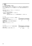
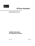
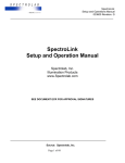
Chapter 4 IInstallation and Wiring 4.3.7 PAUSE Input This input is enabled in the controller mode. The PAUSE input is used to temporarily stop the operating slider / cylinder (operation data is held). To resume the operation, switch the PAUSE input to the non-active state and then activate the START input. When an operation is paused via the PAUSE input, the READY output, MOVE output and END output will change their status as follows: Note If the PAUSE input is active, operation cannot be performed even when the START input is activated. Output Status During Pause READY output: Switches from the non-active to active state MOVE output : Switches from the active to non-active state END output : Remains in the non-active state ■ Figure 4-17 PAUSE Input A START input N.A 4 ms or more A PAUSE input N.A A READY output N.A A MOVE output N.A A END output N.A 10 ms or less 10 ms or less Opposite the motor direction Motor operation Motor direction A (active) : ON N.A (non-active): OFF EZS/ EZC Series Controller EZMC36 USER MANUAL 4-15 4.3.8 ACL Input This input is common to the controller mode and driver mode. The ACL input is used to reset the ALM output to the normal, non-active state, when the ALM output has been activated due to an activation of the controller’s protective function. Note that the ACL input cannot reset the protective functions relating to a failure in the motor or controller, nor to the teaching pendant. ■ Figure 4-18 ACL Input 4 ms or more A ACL input N.A 1.3 s or less A READY output N.A A MOVE output N.A A END output N.A 1.3 s or less A ALM output N.A 10 ms or less A ALM0 to ALM4 output 0x00 N.A Opposite the motor direction Motor operation Motor direction A (active) : ON N.A (non-active): OFF 4-16 Chapter 4 IInstallation and Wiring 4.3.9 CW / CCW ( PLS / DIR) Inputs These inputs are enabled in the driver mode. Input the user-defined controller’s pulse train. Input a signal corresponding to the pulse input mode. See p. 3-5 for details on how to set the pulse input mode. ■ Figure 4-19 Circuit for CW / CCW / PLS / DIR Inputs CW + / PLS CCW + / DIR PC410 or equivalent 220Ω 1kΩ CW- / PLS CCW - / DIR (1) 2-pulse input mode ● The slider/cylinder operates in the opposite the motor direction when a pulse train is input to the CW input. ● The slider/cylinder operates in the motor direction when a pulse train is input to the CCW input. The moving part of the slider/cylinder moves by 0.015 mm (0.0006 inch) per one pulse. ■ Figure 4-20 CW / CCW Inputs A CW input N.A A CCW input N.A 3 ms or less ∗1 3 ms or less ∗1 A END output N.A Opposite the motor direction Motor operation Motor direction A (active) : ON N.A (non-active): OFF ∗1 The time after the pulse train input ends until the END output becomes active varies, depending on the load and operating speed. EZS/ EZC Series Controller EZMC36 USER MANUAL 4-17 (2) 1-pulse input mode ● The slider/cylinder operates in the opposite the motor direction when a pulse train is input to the PLS input while the DIR input is active. ● The slider/cylinder operates in the motor direction when a pulse train is input to the PLS input while the DIR input is non-active. The moving part of the slider/cylinder moves by 0.015 mm (0.0006 inch) per one pulse. ■ Figure 4-21 PLS / DIR Inputs A PLS input N.A A DIR input N.A 3 ms or less ∗1 3 ms or less ∗1 A END output N.A Opposite the motor direction Motor operation Motor direction A (active) : ON N.A (non-active): OFF ∗1 The time after the pulse train input ends until the END output becomes active varies, depending on the load and operating speed. (3) Pulse signal: Waveform The waveform of the input pulse signal must have sharp rises and falls, as shown in Figure 4-22. The figure shows voltage levels of a pulse signal. ■ Figure 4-22 Pulse : Waveform H 90% H: 4 to 5V L: 0 to 0.5V L 10% 1 µ s or more 2 µ s or less 4-18 2 µ s or more 2 µ s or less Chapter 4 IInstallation and Wiring 4.3.10 C.OFF Input This input is enabled in the driver mode. ● To prevent injury or equipment damage, do not acti- vate the C.OFF input while the slider/cylinder is operating. If the C.OFF input switches to the active state during operation, the slider/cylinder will stop and lose its holding brake force. ● To prevent injury or equipment damage, never activate the C.OFF input when the slider/cylinder is installed vertically, whether the slider/cylinder is operating or stopped. The holding brake force will be lost, and the load may drop. Warning When the C.OFF input is activated, the motor output current will be cut off ( the slider/cylinder will lose its holding brake force). When operating the slider/cylinder, keep the C.OFF input in the non-active state. ■ Figure 4-23 C.OFF Input 4 ms or less A C.OFF input N.A 250 ms or less Available Motor’s holding brake force Not available A (active) : ON N.A (non-active) : OFF 4.3.11 RUN0 to RUN2 Input These inputs are enabled in the driver mode. The three-bit input is used to set the motor’s operating current as a percentage of the output current. The factory-set internal value can be changed using the teaching pendant. Decrease the operating current when there is an allowance in the slider/cylinder’s thrust force and you wish to reduce vibration during operation or suppress heat generation from the motor. However, be careful of an excessive decrease in current, since the thrust force and holding brake force will also drop in rough proportion to the operating current. ■ Table 4-9 Signal Statues of RUN0 to RUN2 Input RUN2 RUN1 RUN0 Operating current OFF OFF OFF Internal setting (default : 100%) OFF OFF ON 20 % OFF ON OFF 35 % OFF ON ON 50 % ON OFF OFF 60 % ON OFF ON 70 % ON ON OFF 85 % ON ON ON 100 % OFF: Non-active, ON: Active EZS/ EZC Series Controller EZMC36 USER MANUAL 4-19 4.3.12 STOP0 to STOP2 Input These inputs are enabled in the driver mode. The three-bit input is used to set the motor’s standstill current as a percentage of the output current. If the standstill current (%) is set higher than the operating current (%), the standstill current will revert to the operating current (%). The factory-set internal value can be changed using the teaching pendant. Decrease the standstill current when there is an allowance in the slider/cylinder’s thrust force and you wish to suppress heat generation from the motor. However, be careful of an excessive decrease in current, since the thrust force, holding brake force and starting characteristics will also drop in rough proportion to the standstill current. ■ Table 4-10 Signal Statuses of STOP0 to STOP2 Input STOP2 STOP1 STOP0 Standstill current OFF OFF OFF Internal setting (default : 50%) OFF OFF ON 20 % OFF ON OFF 35 % OFF ON ON 50 % ON OFF OFF 50 % ON OFF ON 50 % ON ON OFF 50 % ON ON ON 50 % OFF: Non-active, ON: Active ■ Figure 4-24 Operating Current and Standstill Current A RUN0 to RUN2 N.A 5 ms or less Motor current Refresh standstill current A STOP0 to STOP2 input N.A 5 ms or less Motor current 4-20 Refresh standstill current Chapter 4 IInstallation and Wiring 4.3.13 READY Output This output is enabled in the controller mode. The READY output is used to indicate whether or not a slider/cylinder operation command can be accepted. When the READY output is active, the M0 to M5 inputs, START input and HOME input are accepted. If the PAUSE input becomes active, the READY output switches from the non-active to active state. The MOVE output switches from the active to non-active state. The END output remains non-active. 4.3.14 END Output This output is enabled in the controller mode and driver mode. The END output is used to indicate that a positioning operation or return-to-home operation of the slider/cylinder is completed. The END output becomes active when the rotor stops at a position less than ±1.8 degrees from the commanded value after the operation ends. When the PAUSE input is active, the END output remains in the non-active state. The minimum operating speed at which an END signal can be output is 3.6 mm/s (0.14 in/sec). An accurate signal may not be output if the operating speed is lower than 3.6 mm/s (0.14 in/sec). 4.3.15 MOVE Output This output is enabled in the controller mode. The MOVE output becomes active when an operation-status signal is output indicating that the slider/cylinder is operating. When the PAUSE input becomes active, the slider/cylinder will stop and the MOVE output will switch from the active to non-active state. 4.3.16 AREA Output This output is enabled in the controller mode. The AREA output is used to indicate that the moving part of the slider/cylinder is staying inside the set area ( between the upper and lower limits). The AREA output is active while the moving part of the slider/cylinder is inside the set area. The area is set via the teaching pendant. An AREA signal is output regardless of whether the slider/cylinder is operating or stopped. ■ Figure 4-25 Explanation of AREA Output Area 2 setting (lower limit) Area 1 setting (upper limit ) Home position Note ● Response of AREA output If the same value is set for areas 1 and 2, the maximum operating speed at which an AREA signal can be output will be 20 mm / s (0.79 in / sec). The maximum operating speed for AREA signal output will increase to 40 (1.57 in/sec), 60 (2.36 in/sec) and 80 mm/s (3.15 in/sec) when the AREA output range is incremented by 0.015 mm (0.0006 inch) to 0.015 (0.0006 inch), 0.03 (0.0012 inch) and 0.045 mm (0.0018 inch), respectively. ● The AREA output generates a maximum delay of 1 ms. Rod limit position (lower limit) Rod limit position (upper limit) A When Area 1 > Area 2 AREA output N.A A When Area 1 < Area 2 AREA output N.A A (active) : ON N.A (non-active): OFF When Area 1 = Area 2, the AREA output becomes active only when the slider/cylinder is at the set position. EZS/ EZC Series Controller EZMC36 USER MANUAL 4-21 ■ Figure 4-26 AREA Output When Area 1 > Area 2 Selection of operation data M0 to M5 input A START input N.A A READY output N.A A MOVE output N.A A END output N.A A AREA output N.A Opposite the motor direction Motor operation Motor direction A (active) : ON N.A (non-active): OFF 4-22 Area 2 setting Area 1 setting Chapter 4 IInstallation and Wiring 4.3.17 T- UP Output This output is enabled in the controller mode. The T- UP output is used to indicate that a push-motion operation has been completed. The T- UP output becomes active when a pushed condition is achieved inside the pushdistance range (Figure 4-27). If the pushed condition is not achieved, the cylinder will move by the set range and the END output will become active when the movement is complete. See 6.2, “Push-Motion Operation ”, on p. 6-5 for details on the push-motion operation. ■ Figure 4-27 T- UP Output ( pushed condition achieved ) A START input N.A A END output N.A 4 ms or less A T-UP output N.A Push distance Opposite the motor direction Motor operation Motor direction A (active) : ON N.A (non-active): OFF ■ Figure 4-28 T- UP Output ( pushed condition not achieved ) A START input N.A A END output N.A 4 ms or less A T-UP output N.A Push distance Opposite the motor direction Motor operation Motor direction A (active) : ON N.A (non-active): OFF EZS/ EZC Series Controller EZMC36 USER MANUAL 4-23 4.3.18 ALM Output This output is common to the controller mode and driver mode. The ALM output is used to indicate an actuation of the controller’s protective function. When the ALM output becomes active, an ALM code (ALM0 to ALM4) explained below will also be output. The ALM0 to ALM4 output is enabled when the ALM output is active. ■ Figure 4-29 ALM Output Occurrence of alarm A READY output N.A 5 ms or less A MOVE output N.A A END output N.A 4 ms or less A ALM output N.A 4 ms or less A ALM0 to ALM4 output N.A 0x00 Opposite the motor direction Motor operation ∗1 Motor direction A (active) : ON N.A (non-active): OFF ∗1 The time until the motor stops varies, depending on the load and operating speed. 4.3.19 ALM0 to ALM4 Output These inputs are common to the controller mode and driver mode. The five-bit code comprised of ALM0 to ALM4 signals is output simultaneously with an ALM output and indicates the number of LED blinks corresponding to the protective function that has triggered the ALM output. See 5.4, “Troubleshooting ”, on p. 5-4 for details. ■ Table 4-11 Signal Statuses of ALM0 to ALM4 Output ALM4 ALM3 ALM2 ALM1 ALM0 OFF OFF OFF OFF OFF 0 (normal state) OFF OFF OFF OFF ON 1 OFF OFF OFF ON OFF 2 OFF OFF OFF ON ON 3 OFF OFF ON OFF OFF 4 OFF OFF ON OFF ON 5 OFF OFF ON ON OFF 6 OFF OFF ON ON ON 7 OFF ON OFF OFF OFF 8 OFF ON OFF OFF ON 9 OFF: Non-active, ON: Active 4-24 Number of LED blinks Chapter 4 IInstallation and Wiring 4.3.20 TIM Output This output is enabled in the driver mode. The TIM output is used to indicate that the rotor has turned 7.2 degrees. The TIM output is enabled when it is active. The active range is determined by the operating speed of the slider/cylinder. (A TIM signal is output when the operating speed is 7.5 mm / s (0.30 in / sec) or below.) ■ Figure 4-30 TIM Output A 16 1 32 Pulse train input N.A A TIM output N.A Rotor rotation by 7.2 degrees, movement by 0.24 mm (0.0094 inch) Motor operation Operating A (active) : ON N.A (non-active): OFF ■ Figure 4-31 TIM Output Circuit 21 TLP181 or equivalent 22 EZS/ EZC Series Controller EZMC36 USER MANUAL 4-25 4.4 Sensor I / O Specification This section describes the controller’s sensor input. The sensor input is enabled in the controller mode. Use an optional sensor set ( PAEZ-S ) for the sensors. For the sensor power supply, always use the +24 V and GND outputs provided for sensor I / O. ■ Figure 4-32 Input Circuit PS2801 or equivalent COM 680Ω Input ∗ 4.7kΩ ∗ +LS, -START, HOMELS 4.4.1 +LS Input This is the sensor input on the flange side (opposite the motor side). During operation other than return-to-home: Detects a mechanical limit and stops the slider/cylinder. During return-to-home operation: Supports home-position detection in accordance with the return-to-home operation pattern. The input logic can be set to normally-open (contact A) or normally-closed (contact B). However, the logic must be the same for both the + LS and -LS. 4.4.2 -LS Input This is the sensor input on the bracket side (motor side). During operation other than return-to-home: Detects a mechanical limit and stops the slider/cylinder. During return-to-home operation: Supports home-position detection in accordance with the return-to-home operation pattern. The input logic can be set to normally-open (contact A) or normally-closed (contact B). However, the logic must be the same for both the + LS and -LS. 4.4.3 HOMELS Input This input detects the mechanical home position when a return-to-home operation is executed in the 3 - sensor mode. The input logic can be set to normally-open (contact A) or normally-closed (contact B). 4.4.4 +24 V / GND Outputs These are power outputs used for sensors. Two output circuits having the same power supply are provided. 4-26 Chapter 4 IInstallation and Wiring 4.4.5 Return-to-Home Operation Sequence Return-to-home is an operation in which the sensor placed at the reference point of positioning (mechanical home position) is detected automatically. The home position can be detected in two modes: the 2-sensor mode (constant-speed operation) and 3-sensor mode (high-speed operation). The starting direction of home-position detection is determined by the direction of movement. In both the 2-sensor mode and 3-sensor mode, the operation sequence depends on the starting direction of home-position detection and the current position. In the 2sensor mode, a rectangular operation is performed at the starting speed. ■ 2 - Sensor Mode Broken line indicates a home offset Starting position of Starting direction of return-to-home operation: Starting direction of return-to-home operation: return-to-home Opposite the motor side Motor side operation -LS -LS +LS Opposite the motor side Opposite the motor side Motor side Motor side -LS +LS +LS Opposite the motor side Opposite the motor side Motor side Motor side -LS Between -LS and +LS +LS Opposite the motor side Opposite the motor side Motor side Motor side ■ 3 - Sensor Mode -LS +LS -LS +LS -LS +LS Broken line indicates a home offset Starting position of Starting direction of return-to-home operation: Starting direction of return-to-home operation: return-to-home Opposite the motor side Motor side operation -LS -LS Motor side Motor side Motor side Motor side HOMELS +LS Opposite the motor side Opposite the motor side Motor side Motor side HOMELS +LS Opposite the motor side Opposite the motor side Motor side Motor side -LS Between HOMELS and +LS +LS Opposite the motor side -LS Between HOMELS and -LS HOMELS Opposite the motor side -LS HOMELS +LS Opposite the motor side -LS +LS HOMELS Opposite the motor side HOMELS +LS Opposite the motor side Opposite the motor side Motor side Motor side -LS HOMELS +LS -LS HOMELS +LS -LS HOMELS +LS -LS HOMELS +LS -LS HOMELS +LS EZS/ EZC Series Controller EZMC36 USER MANUAL 4-27 4.5 Emergency Stop Specification The emergency stop function is designed under the following specification: ● Design and risk evaluation of the safety circuit is the responsibility of the customer that manufactures the machine. Refer to the safety standards EN954-1 and EN602041 and observe the requirements. Warning Detection condition : An opening of input is detected [ normally-closed (contact B) input ]. Action upon detection: The motor power is forcibly cut off using a hardware circuit rather than through CPU instruction, in order to stop the slider/cylinder (via a coasting stop). If the slider/cylinder is equipped with an electromagnetic brake, the electromagnetic brake will be actuated to provide the necessary holding brake force. To move the slider/cylinder’s moving part, turn the electromagnetic brake release switch to “OFF ” and release the electromagnetic brake. The load may drop if the slider/cylinder is installed vertically. Table 4-12 shows the safety category and stop category of emergency stop and the applicable standards. ■ Table 4-12 Categories and Applicable Standards Note Provide a measure on the machine side so that the machine will operate safely when the slider/cylinder is stopped. 4-28 Item Category Safety category 1 EN954-1 Stop category 0 EN60204-1 Applicable standard Chapter 4 IInstallation and Wiring Figure 4-33 shows a timing chart of the EMG (emergency stop) input. ■ Figure 4-33 Timing Chart of EMG (Emergency Stop) Input Motor is operating A Emergency stop in process EMG input N.A 700 ms or less A READY output N.A 6 ms or less A MOVE output N.A A END output 4 ms or less 700 ms or less 6 ms or less 10 ms or less A ALM output N.A A ALM0 to ALM4 output 0x00 0x00 N.A Opposite the motor direction Motor operation Motor direction 600 ms or less 25 ms or less Motor s holding brake force Available Not available 650 ms or less 30 ms or less Electromagnetic brake Released Holding Released Motor is stopped A EMG input N.A A READY output Emergency stop in process 6 ms or less 700 ms or less N.A A (active) : ON N.A (non-active): OFF EZS/ EZC Series Controller EZMC36 USER MANUAL 4-29 4.6 Wiring the Power Cable Connect a 24 VDC power supply to the power cable. ● Use a DC power supply providing reinforced insulation on the primary and secondary sides. ● Use a three-core shield cable of AWG20 (0.5 mm2 ) or larger to wire the power sup- ply. ● Connect the shield cable to the FG lead of the power cable. ● Keep the wiring between the power supply and controller to a distance of 3 m (9.8 ft.) or less. Note ● Do not connect the power supply in reverse polarity. Check the connections again once the power supply is wired. ● Prevent the connector from receiving mechanical stress such as bending force or tensile force. Table 4-13 shows the pin assignments of the power-supply connector. ■ Table 4-13 Pin Assignments of Power-Supply Connector Color of power cable lead 1 Brown 2 Controller power ground Blue 3 Frame ground White Pin Signal name 1 +24V Controller power input 2 GND 3 Explanation 4.6.1 Supplied Power 1. Provide a dedicated power source, not one shared with other equipment. 2. Use a power supply with an overcurrent protection circuit. 3. Connect a mains filter on the input side of the power supply. 4. Connect a surge absorber on the input side of the power supply. 4.6.2 Power-Supply Protection The controller’s power supply has a built-in 7 A fuse of fixed type. In the event the fuse blows, call our Technical Support Line. 4.6.3 Insulation Resistance Measurement / Dielectric Strength Test Measure insulation resistance and test dielectric strength by shorting all terminals of the controller, including the power, motor, encoder, I / O and communication terminals. Conduct the measurement / test on an individual controller. ● Conducting the test without shorting all terminals will Warning damage the controller. ● To prevent electric shock, do not touch the terminals when conducting the test. 4.6.4 Grounding Work ● Provide protective grounding for the mains filter and DC power supply. ● Provide a dedicated ground circuit. ● Use a wire of AWG16 (1.5 mm2 ) or larger for the ground lead. 4-30 Chapter 4 IInstallation and Wiring 4.7 Wiring the Emergency Stop Cable Connect the emergency stop circuit to the emergency-stop terminal block (EMG). (Remove the jumper cable installed at the factory.) ● The emergency stop input of the controller is a normally-closed (contact B) input. Table 4-14 shows the pin assignments of the emergency-stop terminal block. Table 4-15 shows the specifications of conforming and usable wires. ● Design and risk evaluation of the safety circuit is the Warning responsibility of the customer that manufactures the machine. Refer to the safety standards EN954-1 and EN602041 and observe the requirements. ■ Table 4-14 Pin Assignments of Emergency-Stop Terminal Block Pin Signal name Explanation 1 EMG + Emergency stop input + 2 EMG - Emergency stop input - 1 2 ■ Table 4-15 Conforming / Usable Wires Conforming wire Usable wire Solid wire : ø1.2 mm (ø0.05 inch) Stranded wire : AWG16 (1.25 mm2 ) Solid wire : ø0.4 mm to ø1.2 mm (ø 0.02 inch to ø 0.05 inch) Stranded wire : 0.3 mm2 to 1.25 mm2 (AWG22 (0.3 mm2 ) to AWG16 (1.25 mm2 )) [strand diameter: ø 0.18 mm (ø 0.01 inch) or more ] Standard strip length 6 to 8 mm (0.24 to 0.33 inch) Conforming tool for button operation Flat-head screwdriver [ shaft diameter: ø3 mm (ø 0.12 inch), blade tip width: 2.6 mm (ø 0.10 inch) ] 4.8 Wiring / Charging the Battery If the controller is of the absolute type, connect the battery to the battery connector (socket) on the controller. Follow the procedure below when charging the battery for the first time: 1. Connect the battery to the controller. 2. Supply the power to the controller. The battery starts charging. It takes approx. 48 hours to fully charge the battery [at an ambient temperature of 20°C (68°F) ]. Once the battery is fully charged, turn off the power to the controller after removing the battery. Note The product is shipped with an uncharged battery. Always charge the battery before use. Connect all cables to the controller, supply the power to the controller, and then connect the battery. The battery is always charging while the power is being supplied to the controller. EZS/ EZC Series Controller EZMC36 USER MANUAL 4-31 4.9 Wiring the Slider / Cylinder Cables This section explains the wiring of the motor cable and encoder cable of the slider/cylinder. 4.9.1 Connecting the Slider / Cylinder Plug the connectors (plugs) at the ends of the motor cable and encoder cable of the slider/cylinder into the corresponding connectors (sockets) on the controller. ■ Figure 4-34 Slider / Cylinder Connection Controller Encoder connector (ENC) LINEAR mOTION CONTROLLER EZmC 36 PWR F01 89 67 A E BCD 4 23 5 ID RDY ALM 1 2 ON 3 4 Slider /cylinder Encoder cable SW OFF ON MB OFF ON PENDANT ENC PENDANT/PC LINK MOTOR BAT I/O EMG Motor connector (MOTOR) 24V DC Motor cable 4.9.2 Cable Wiring Length Always use an optional cable set when extending the slider/cylinder wiring. Keep the overall extension length to 10 m (32.8 ft.) or less. Note ● Do not modify the motor/encoder ca- bles in any way. Do not extend the motor/encoder cables by connecting two or more extension cables or allow the overall extension length to exceed 10 m (32.8 ft.). Doing so may cause a malfunction. ● Secure the cable so the connector joint will not move. ● Prevent the connectors (sockets) on the controller side from receiving mechanical stress such as bending force or tensile force. Cable set : Motor / encoder cables (set of two cables) Model Cable length CC02EZ1 2 m (6.6 ft.) CC05EZ1 5 m (16.4 ft.) CC10EZ1 10 m (32.8 ft.) Flexible cable set : Motor / encoder cables (set of two cables) Model Cable length CC02EZ1R 2 m (6.6 ft.) CC05EZ1R 5 m (16.4 ft.) CC10EZ1R 10 m (32.8 ft.) 4.9.3 Protecting the Motor The controller provides motor protection functions that operate under the conditions specified below: Overheat Protection When actuated, the overheat protection function stops the motor (cuts the power to the motor). ● When a signal from the encoder’s built-in temperature sensor has been output to the controller. Overload Protection When actuated, the overload protection function stops the motor (cuts the power to the motor). ● When a load exceeding the maximum torque has been applied for five seconds or more during an operation other than push-motion operation or sensor-less, returnto-home operation. 4-32 Chapter 4 IInstallation and Wiring 4.10 Wiring the Communication Connector Cables A maximum of 16 controllers can be connected to the teaching pendant in a “ daisy chain ” using controller link cables (optional). 4.10.1 Teaching Pendant Plug the connector (plug) at the end of the teaching pendant cable into the pendant connector (PENDANT/PC) on the controller. ■ Figure 4-35 Connection of Teaching Pendant Controller Teaching pendant BCD E PWR F01 23 ID 7 8 9A LINEAR mOTION CONTROLLER EZ mC 36 RDY ALM 456 1 2 ON 3 SW 4 ER G E N C Y ST O ON MB Connector (plug) P EM TEACHING PENDANT EZT1 OFF OFF ON PENDANT F1 F2 ESC F3 F4 ENC SATART STOP PENDANT/PC SHIFT BS 7 8 9 +/- 4 5 6 1 2 3 0 Pendant connector (PENDANT/PC) LINK MOTOR ENT BAT I/O 24V DC EMG Pendant cable Note ● Turn the PENDANT switch to “ON” after connecting the teaching pendant. When disconnecting the teaching pendant from the controller, always turn the PENDANT switch to “OFF ”. Disconnecting the teaching pendant while the PENDANT switch is set to “ON” will cause the controller to execute an emergency stop. ■ Figure 4-36 PENDANT Switch OFF ON 4.10.2 Controller Follow the procedure below when connecting two or more controllers via a daisy chain. ● Use optional controller link cables [ CC002EZ1-L: 0.2 m (0.7 ft.) ] for the connec- tion. 1. Determine the controller to which the teaching pendant is directly connected. ( The emergency stop button on the teaching pendant will be enabled when the teaching pendant is connected to the controller. ) 2. Connect the link connector ( LINK ) on the controller directly connected to the teaching pendant, to the pendant connector ( PENDANT / PC ) on the second controller. 3. When three or more controllers are connected, follow the same procedure to connect the link connector ( LINK ) on each subsequent controller to the pendant controller ( PENDANT / PC ) on the next controller. Warning ● The emergency stop button on the teaching pendant will be effective only for the controller directly connected to the teaching pendant. EZS/ EZC Series Controller EZMC36 USER MANUAL 4-33 ■ Figure 4-37 Connection of Communication Connectors EM TEACHING PENDANT EZT1 F1 F2 ESC F3 ER P Teaching pendant G E N C Y ST O F4 Controller link cable SATART STOP SHIFT Controller Controller LINEAR mOTION CONTROLLER EZmC 36 LINEAR mOTION CONTROLLER EZmC 36 4 ON RDY ALM 3 OFF PWR OFF MB ON OFF ON OFF PENDANT ENC PENDANT/PC LINK PENDANT/PC LINK MOTOR BAT LINK DC 24V DC 24V Link connector (LINK) BAT I/O EMG 1st controller Pendant connector (PENDANT/PC) MOTOR BAT I/O EMG ON PENDANT ENC PENDANT/PC MOTOR ON MB 2nd controller I/O EMG DC 456 PENDANT ENC Pendant cable BCD 1 2 ON SW MB OFF ID RDY ALM F01 ON 4 4 OFF PWR 3 3 SW E BCD 1 2 ON 1 2 ON SW ID RDY ALM F01 F01 PWR E BCD E ID 7 8 9A Controller LINEAR mOTION CONTROLLER EZmC 36 24V ENT 7 8 9A 0 7 8 9A 3 23 6 2 456 9 5 1 23 8 4 456 7 23 BS +/- 3rd controller 4.11 Wiring the I / O Cable Use the supplied connector set to plug the connector (socket) on the cable into the I / O connector on the controller. Use a shield cable of AWG28 (0.09 mm2 ) or larger for the I / O cable, and keep the wiring distance as short as possible. Shielded cable is available as an option. A half-pitch connector (socket) is provided at one end of the cable. ■ Figure 4-38 Connection of I / O Connector Controller BCD EF PWR 01 23 ID 7 8 9A LINEAR mOTION CONTROLLER EZmC 36 RDY ALM 456 1 2 ON 3 SW 4 OFF ON MB OFF ON PENDANT ENC PENDANT/PC LINK 4-34 BAT I/O EMG DC The input/output functions of the controller vary, depending on the controller’s operation mode. Before wiring the cables, determine the mode in which the controller will be operated and set the “ operation mode switch ” accordingly. 24V Note MOTOR I/O connector Chapter 4 IInstallation and Wiring 4.12 Wiring the Sensor Cables Plug the connector (socket ) of an optional sensor cable (CC02EZ1-S ) into the sensor connector on the controller’s bottom surface. ■ Figure 4-39 Connection of Sensor Connector Controller Mode Note Controller controller mode is selected. The input is disabled in the driver mode. ● In the 2-sensor mode, use the +LS and -LS sensors, with the -LS sensor as the HOME sensor. LINEAR MOTION CONTROLLER EZmC 36 BCD EF PWR 01 23 ID 7 8 9A ● The sensor input is enabled when the 456 RDY ALM 1 2 ON 3 SW 4 G OFF ON MB OFF The pink lead (broken line) is connected to the brown lead if the sensor logic is N.C. (normally-closed). If the sensor logic is N.O. (normally-open), the pink lead is not connected. ON PENDANT ENC PENDANT/PC LINK MOTOR Pink Red BAT I/O Purple DC EMG 24V Gray DC24V +LS GND Brown Black +LS sensor Blue Pink Brown Sensor connector Yellow Blue Connector on bottom surface DC24V - LS GND Brown Black -LS sensor Blue Pink Orange Green Sensor connector White DC24V HOME GND Brown Black HOME sensor Blue The 24 VDC output from the controller is used to drive the sensors. Do not use it as a power supply for any item other than the sensors. Bottom surface Driver Mode Sensor power +5 to +24 V The pink lead (broken line) is connected to the brown lead if the sensor logic is N.C. (normally-closed). If the sensor logic is N.O. (normally-open), the pink lead is not connected. User-defined controller Pink DC24V +5 to +24 V +LS +LS sensor GND CC02EZ1-S 2 m ( 6.6 ft.) -LS sensor - LS Black R0 GND HOME sensor R0 ● Sensor Set Model PAEZ-S +LS sensor Blue Pink DC24V ● Sensor Cable Cable length Black Black R0 Model Brown Black Sensor wire connection The power supply must be 5 VDC or more and 24 VDC or less. The current must not exceed 100 mA. If the current exceeds 100 mA, connect an external resistance R0. Brown Black -LS sensor Blue Pink DC24V HOME GND Brown Black HOME sensor Blue EZS/ EZC Series Controller EZMC36 USER MANUAL 4-35 4.13 Compliance with the EC Directives The EZS / EZC Series controllers and sliders/ cylinders bear the CE mark indicating their compliance with the following EC directives. The installation conditions needed to satisfy the EC directives are as follows: 1. For the power supply to the controller, use an EMC-compliant DC power supply with reinforced insulation provided on the primary and secondary sides. 2. Install an AC line filter on the input side of the DC power supply. When a power transformer is used, always connect an AC line filter on the AC input side of the power transformer. 3. Use optional cables for slider/cylinder connection. 4. Install the slider/cylinder and controller in an industrial-grade enclosure so that only appropriate qualified personnel can access these parts. The EZS / EZC Series controllers, sliders/ cylinders and the teaching pendant use an input power-source voltage of 24 VDC and thus are excluded from the scope of the Low-Voltage Directive. However, it is recommended that the following precautions be observed when installing and wiring the product. ● Protect the product within an enclosure during use. ● For the controller’s power supply, use an EMC-compliant DC power supply with re- inforced insulation provided on the primary and secondary sides. 4.13.1 EMC Directives (89/336/EEC, 92/31/EEC) The EZS / EZC Series controllers, sliders/ cylinders and the teaching pendant have been confirmed to comply with the standards below by conducting EMC measurements in accordance with 4.14.3, “ Example of EMC - Compliant Wiring ”, on p. 4-42. The degree of EMC compliance with respect to a given machine depends on the configuration, wiring, installation conditions and hazard level of other control systems equipment and electrical parts used with the controller and slider/cylinder. Therefore, it is the customer’s responsibility to perform EMC measurements and confirm EMC compliance with respect to a given machine. Applicable Standards EMI Emission Tests Radiated Emission Test EN50081-2 EN55011 EMS Immunity Tests Radiation Field Immunity Test Electrostatic Discharge Immunity Test Fast Transient / Burst Immunity Test Conductive Noise Immunity Test EN61000-6-2 IEC61000-4-3 IEC61000-4-2 ∗1 IEC61000-4-4 ∗2 IEC61000-4-6 ∗1 Pendant: 10 kV both in air and in the contact state Controller: Malfunction or damage may occur due to static electricity. When touching the controller, cut off the power supply or provide an antistatic measure. Always use an insulated screwdriver when adjusting the controller’s axis - number setting switch, electromagnetic brake release switch, pendant switch or DIP switches. ∗2 Injection to pendant cable through clamp: 1 kV Injection to the encoder, motor, power and I / O cables through clamp: 2 kV 4-36 Chapter 4 IInstallation and Wiring 4.13.2 Installation / Wiring Methods Appropriate measures must be taken to suppress the EMI (Electromagnetic Interference) caused by the EZS / EZC Series slider/cylinder and teaching pendant in the nearby control systems equipment and to address the EMS (Electromagnetic Susceptibility) of the EZS / EZC Series controller, slider/cylinder and teaching pendant. Failure to do so may result in a serious impairment of machine functions. The basic wiring requirements for the EZS / EZC Series controller, slider/cylinder and teaching pendant are described below: (1) Power supply The EZS/EZC Series products are specified for DC power input. Use a DC power supply compliant with the EMC directives. (2) Mains filter Connect a mains filter on the input side of the DC power supply in order to prevent noise generated in the controller from being transmitted outward via the power line. When a power transformer is used, always connect a mains filter on the AC input side of the power transformer. Oriental Motor recommends the mains filters shown in the table below, based on our internal measurement results. Manufacturer Model CORCOM 10ESK1 TDK ZAG2210-115 ● Install the mains filter in a position as close as possible to the DC power supply or power transformer. Also, secure the input and output cables using cable clamps, etc., so the cables won’t lift from the surface of the enclosure. ● Use as thick a cable as possible for the ground terminal of the mains filter, and connect the terminal to the ground point over the shortest possible distance. ● Do not wire the cable on the AC input side and the output cable of the mains filter in parallel. Wiring these cables in parallel connects the noise inside the enclosure to the power cable via stray capacitance, thus reducing the effect of the mains filter. (3) Grounding method When grounding the controller, mains filter and DC power supply, use as thick a cable as possible and connect to the ground point over the shortest possible distance so as not to generate potential difference at the grounded section. Use a wide, thick and uniform conducting surface for the ground point. Install the slider/cylinder onto a grounded metal surface. (4) Wiring the I/O and encoder cables Use a shielded cable with a conductive cross-sectional area of AWG28 (0.09 mm2 ) or larger for the controller I/O cable, and wire the cable over as short a distance as possible. (A shielded cable is available as an option.) Use a metal cable clamp that contacts the shielded cable along its entire circumference to secure/ground the I/O cable or encoder cable. Attach a cable clamp to the tip of the shielded cable, and connect the clamp to an appropriate ground point. ■ Figure 4-40 Cable Clamp Shielded cable Cable clamp EZS/ EZC Series Controller EZMC36 USER MANUAL 4-37 (5) Wiring other cables ● Connect the cable directly to the ground point so as not to generate a differ- ence in ground potential between the controller and any surrounding control systems equipment. ● When using a regular or electromagnetic relay in the same circuit, apply a mains filter or CR circuit in order to absorb any surge current. ● Wire the cable over as short a distance as possible, and do not roll up or bundle the extra length. ● Divide the cables into power cables—such as the motor cable and power-supply cable—and signal cables, and wire them separately by maintaining a clearance of around 100 to 200 mm (4 to 8 inch). If a power cable must cross a signal cable, let them cross at relative right angles. Keep a distance between the AC input-side cable and output-side cable of the mains filter. (6) Precautionary note on static electricity Static electricity may cause the controller to malfunction or sustain damage. Do not touch the controller while power is being supplied. When adjusting the controller’s axis-number setting switch, brake-release switch, pendant switch or DIP switches while power is being supplied, be sure to use an insulated screwdriver. 4-38 Chapter 4 IInstallation and Wiring 4.14 Wiring Diagrams This section gives power and I/O wiring diagrams for the EZS/EZC Series controller and an example of EMC-compliant wiring. 4.14.1 Power Wiring Diagram An example of wiring the DC input and slider/cylinder cables to the EZMC36 controller is shown below: ■ Figure 4-41 Example of Standard Power Wiring for EZMC36 Controller Slider Controller m m Teaching pendant Encoder cable Motor cable Emergency stop switch Mains filter DC power supply AC100V 50/60Hz Normally-closed (contact B) Surge absorber Protective ground Enclosure ground Conforming cable Application of cable Solid wire Stranded wire AWG18 (0.75 mm2 ) Grounding DC power supply Emergency stop ø1.2 mm (ø0.05 inch) (AWG18) AWG20 (0.5 mm2 ), shielded cable AWG18 (0.75 mm2 ) ● Motor / Encoder Cables (optional) Length Motor cable model Encoder cable model Set model 2 m (6.6 ft.) CC02EZ1-M CC02EZ1-E CC02EZ1 5 m (16.4 ft.) CC05EZ1-M CC05EZ1-E CC05EZ1 10 m (32.8 ft.) CC10EZ1-M CC10EZ1-E CC10EZ1 ● Recommended Mains Filters Manufacturer Model TDK ZAG2210-115 CORCOM 10ESK1 ● 24 VDC Power Supply Input voltage 100 VAC, 50/60 Hz Output voltage 24 VDC ±10% Output current 4.0 A or more Other Reinforced insulation type EZS/ EZC Series Controller EZMC36 USER MANUAL 4-39 4.14.2 I / O Wiring Diagrams Examples of wiring the user I / Os to the EZMC36 controller are shown below: ■ Figure 4-42 Example of Standard I / O Wiring for EZMC36 Controller (controller mode) Controller Mode I/O connector LINK MOTOR PAUSE +COM HOME -COM AREA COM T-UP COM M0 I/O connector BAT I/O M1 M2 24V DC EMG ALM0 M3 ALM1 M4 ALM2 M5 19 ENC PENDANT/PC 36 34 32 30 28 26 24 22 20 35 33 31 29 27 25 23 21 19 +COM -COM 36 MOVE START ON PENDANT 1 456 4 MB OFF 18 16 14 12 10 8 6 4 2 17 15 13 11 9 7 5 3 1 23 3 END ON OFF Viewed from the soldered surface STOP RDY ALM 1 2 ON Set the operation mode switch to OFF. Connector (plug) pin assignments 19 PWR 01 SW 1 ALM BCD EF ID 7 8 9A LINEAR mOTION CONTROLLER EZmC 36 18 READY ALM3 ALM4 18 36 ALM ■ Figure 4-43 Example of Standard I / O Wiring for EZMC36 Controller (driver mode) Driver Mode I/O connector -COM +COM C.OFF PENDANT/PC -COM LINK COM COM MOTOR RUN0 I/O connector BAT I/O 24V DC EMG RUN1 RUN2 ALM1 STOP1 ALM2 STOP3 ALM3 CW+(PLS) ALM4 CW-(PLS) 18 4-40 ALM0 STOP0 36 ALM 19 ON PENDANT 36 34 32 30 28 26 24 22 20 35 33 31 29 27 25 23 21 19 4 OFF ENC 36 3 TIM+COM MB 1 456 1 2 ON END ON Viewed from the soldered surface 18 23 7 8 9A TIM+ RDY ALM OFF Connector (plug) pin assignments CCW-(DIR) PWR 01 SW Set the operation mode switch to ON. ALM CCW+(DIR) BCD EF ID 19 18 16 14 12 10 8 6 4 2 17 15 13 11 9 7 5 3 1 1 LINEAR mOTION CONTROLLER EZmC 36 Chapter 4 IInstallation and Wiring ■ Figure 4-44 Example of User-Defined Controller Connection (controller mode) Controller Mode EZMC36 controller User-defined controller 24 VDC 23,25 27,28 +COM COM 24 VDC inputs 11 M0 12 M1 13 M2 14 M3 Data selection inputs 15 M4 16 M5 3 STOP 6 START 7 PAUSE 8 HOME Control inputs 36 ACL 24,26 -COM V0 (5 VDC to 24 VDC) R0 1 READY R0 2 ALM 4 END 5 MOVE 9 AREA R0 R0 R0 R0 R0 R0 R0 R0 R0 10 T-UP Control outputs 31 ALM0 32 ALM1 33 ALM2 34 ALM3 35 ALM4 Note V0 must be inside a range of 5 to 24 VDC. The current must not exceed 25 mA. If the current exceeds 25 mA, connect an external resistance R0. EZS/ EZC Series Controller EZMC36 USER MANUAL 4-41 ■ Figure 4-45 Example of User-Defined Controller Connection (driver mode) Driver Mode EZMC36 controller User-defined controller 24 VDC 23,25 27,28 + COM COM 24 VDC inputs 11 RUN0 12 RUN1 13 RUN2 14 STOP0 Motor-current setting inputs 15 STOP1 16 STOP2 5 VDC 17 CW+ 18 CW- 5 VDC 19 CCW+ Motor pulse inputs 20 CCW7 C.OFF Control inputs 36 ACL 24,26 -COM V0 (5 VDC to 24 VDC) R0 2 ALM R0 4 END R0 R0 R0 R0 31 ALM0 32 ALM1 33 ALM2 34 ALM3 R0 35 ALM4 R0 21 TIM+ 22 TIM- Connect the home-position detection sensors to the user-defined controller. Note V0 must be inside a range of 5 to 24 VDC. The current must not exceed 25 mA. If the current exceeds 25 mA, connect an external resistance R0. 4-42 Control outputs Chapter 4 IInstallation and Wiring 4.14.3 Example of EMC-Compliant Wiring An installation/wiring example of the controller, slider/cylinder and teaching pendant used in the EMC measurement conducted by Oriental Motor is shown below: ■ Figure 4-46 Example of Installation/Wiring Compliant with EMC Directives Teaching pendant F2 ESC F3 ER G P EM TEACHING PENDANT EZT1 F1 EN C Y S T O F4 SATART STOP SHIFT BS 7 8 9 +/- 4 5 6 1 2 0 3 ENT Slider / cylinder Pendant cable: 5 m (16.4 ft.) (Shielded cable) Controller BCD RDY ALM (Shielded cable) 23 45 3 SW User-defined controller PWR 1 2 ON 4 Encoder cable (Shielded cable) F01 67 E ID 8 9A LINEAR mOTION CONTROLLER EZ mC 36 OFF ON I/O cable MB A OFF ON PENDANT ENC Motor cable (Shielded cable) PENDANT/PC LINK MOTOR DC power supply A BAT I/O ∗ 24V A EMG DC Mains filter AC PE PE Grounded panel A: Cable clamp ∗ Use braided shielded cable to wire the power supply. Note Some of the parts used in the controller are sensitive to static electricity. When touching the controller, first cut the power or provide an antistatic measure. Touching the controller without cutting off the power or providing an antistatic measure may damage the controller. Note See Appendix B, “Optional Parts and Accessories,” for the cables shown in gray. EZS/ EZC Series Controller EZMC36 USER MANUAL 4-43 4-44 5 Startup and Troubleshooting Chapter 5 Startup and Troubleshooting Chapter Note This chapter explains the procedures used to turn on the power to the controller and start the slider/cylinder, as well as the steps to take in troubleshooting. Some of the parts used in the controller are sensitive to static electricity. When touching the controller, first cut the power or provide an antistatic measure. Touching the controller without cutting off the power or providing an antistatic measure may damage the controller. ● To prevent injury or equipment damage, confirm that all of the controller’s input signals are set to the nonactive state before turning on the power. Also, confirm the emergency stop method of the machine beforehand and operate the slider/cylinder in a condition where an emergency stop can be executed at any moment if necessary. Warning 5.1 Turning on the Power to the Controller The procedure explained in this section assumes that the controller is properly wired and that the slider/cylinder operation data has been set via the teaching pendant. Turn on the power to the controller according to the following procedure: LINEAR mOTION CONTROLLER EZ mC 36 PWR 01 ID BCD EF 789A POWER LED Axis-number setting switch READY/ ALARM LED RDY ALM 456 1 2 ON SW 4 Operation mode switch 3 When the controller is of the absolute type, an alarm will be generated if power is supplied to the controller under the following conditions. Take an appropriate action by referring to “Alarm Codes ” on p. 5-5. ● The battery is not connected ● The battery is not charged ● The battery is used for the first time ■ Figure 5-1 Controller 23 Note ON OFF MB OFF Pendant switch ON PENDANT ENC Note Always connect the battery after the power supply to the controller has been turned on. When connecting the battery, connect all cables to the controller and turn on the power supply to the controller first. ■ Table 5-1 Controller Settings Item Setting Axis-number setting switch ID: 0 Operation mode switch ( No. 4 ) OFF: Controller Pendant switch OFF: Not used 1. If the teaching pendant is not connected, confirm that the pendant switch is set to “OFF ”. Confirm that no external force is applied to the load or moving part of the slider/cylinder, and then turn on the power. 2. Turn on the DC power supply to the controller and check the lighting condition of the two LEDs on the front panel. Figure 5-2 shows the I / O output statuses at power-on. ■ Table 5-2 LED Statuses POWER LED READY/ALARM LED Procedure On (green) On (green) Go to 5.2, “Starting the Slider / Cylinder ”. Off Off Confirm that the input power supply is connected, and then reconnect the power. On (green) On (red) Go to 5.4, “Troubleshooting ”. On (green) Blinking (red) Count the number of blinks and go to 5.4, “Troubleshooting ”. EZS/ EZC Series Controller EZMC36 USER MANUAL 5-1 ■ Figure 5-2 Output Statuses at Power-On (controller mode) Power on Power off Reconnection of power 10 s or more ∗2 ON Power supply OFF 1.5 s or more∗1 A READY output N.A A MOVE output Undetermined N.A 1.5 s or more∗1 A END output Undetermined N.A 1.5 s or more∗1 A ALM output N.A ∗1 ∗2 A (active) : ON N.A (non-active): OFF The time varies, depending on the power supply. The time varies, depending on the power supply. Reconnect the power after confirming that there is no residual supply voltage. ■ Figure 5-3 Output Statuses at Power-On (driver mode) Power on Power off Reconnection of power 10 s or more ∗2 ON Power supply OFF 1.5 s or more∗1 A END output Undetermined N.A 1.5 s or more∗1 A ALM output N.A Pulse train input (PLS) 1.5 s or more∗1 Input not possible A (active) : ON N.A (non-active): OFF ∗1 ∗2 Input possible The time varies, depending on the power supply. The time varies, depending on the power supply. Reconnect the power after confirming that there is no residual supply voltage. 5.2 Starting the Slider / Cylinder (I / O) To perform a positioning operation via user I/Os, start the slider/cylinder according to the following procedure: 1. Activate the HOME input and cause the slider/cylinder to return to home. 2. Select the positioning data using the M0 to M5 inputs. 3. Activate the START input. A positioning operation of the slider/cylinder is executed. 5-2 Chapter 5 Startup and Troubleshooting 5.3 Starting the Slider/Cylinder (teaching pendant) To perform a manual operation using a teaching pendant, start the slider/cylinder according to the following procedure: 1. Confirm that the emergency stop button on the teaching pendant is not pushed in. 2. Plug the connector (plug) of the teaching pendant cable into the pendant connector on the controller. 3. Turn the pendant switch to “ ON ”. 4. Press the F1 key and set the teaching pendant to “ TST mode ”. 5. Press the F3 key and select [Mnu] to call the manual-operation function. 6. Operate the and keys to manually operate the slider/cylinder. “Controller Data Setting Manual ” for details on setting the operating data. See ■ Figure 5-4 Connection of Teaching Pendant Controller BCD E PWR F01 ID 7 8 9A LINEAR mOTION CONTROLLER EZ mC 36 23 Teaching pendant RDY ALM 456 1 2 ON 3 SW 4 ER G E N C Y ST ON MB P EM TEACHING PENDANT EZT1 OFF O OFF ON PENDANT F1 F2 ESC F3 F4 ENC SATART STOP PENDANT/PC SHIFT BS 7 8 9 +/- 4 5 6 1 2 LINK MOTOR 3 ENT BAT I/O DC EMG 24V 0 Pendant connector (PENDANT/PC) EZS/ EZC Series Controller EZMC36 USER MANUAL 5-3 5.4 Troubleshooting When a controller alarm has been detected, perform troubleshooting with reference to the information provided in this section. If the controller does not operate normally after the appropriate action has been taken, call our Technical Support Line. Table 5-3 shows the number of LED blinks and alarm code corresponding to each controller, wiring or operation-related problem. Figure 5-5 shows the blink pattern of the READY/ALARM LED. When an alarm is detected, the READY/ALARM LED turns on or blinks in red. ( The number of blinks varies, depending on the alarm.) At the same time, the ALM output becomes active, a five-bit code is output via the ALM0 to ALM4 signals to indicate the number of LED blinks corresponding to the protective function that has triggered the alarm, and an alarm code is displayed on the pendant. To clear the alarm code, activate the ACL input (one-shot) or reconnect the power. ● When the alarm is cleared with the ACL input, the system will reset itself in the pow- er-on state. ● If the alarm cannot be cleared with the ACL input, reconnect the power. Note that an alarm arising from a failure in the motor or controller itself cannot be cleared. Should you encounter any such alarm, call our Technical Support Line. ● Following an actuation of the overheat-protection function in the controller or mo- tor, reconnect the power after the controller/motor temperature has dropped to below 40°C (104°F). ■ Figure 5-5 Blink Pattern of READY / ALARM LED Example of blink pattern: Overvoltage-protection function (three blinks) 1 0.25s 5-4 2 3 0.25s 1 1.5s 2 3 Chapter 5 Startup and Troubleshooting ■ Table 5-3 Numbers of LED Blinks and Alarm Codes Alarm No. of LED code blinks Phenomenon Slider/cylinder action Cause Action ACL input 21 Overheat protection Coasts to a stop Power is cut off The driver’s heat-sink temperature reached approx. 85°C. Review the ventilation conditions within the enclosure. Can be used 26 Motor overheat protection Coasts to a stop Power is cut off The motor temperature reached approx. 85°C. Reduce the load. Review the ventilation condition of the surroundings. Can be used 30 Overload Coasts to a stop Power is cut off A load exceeding the maximum thrust force was applied for five seconds or more. Reduce the load or decrease the acceleration. Can be used 31 Overspeed Coasts to a stop Power is cut off The motor speed exceeded 3000 rpm. Set the motor speed to 3000 rpm or less. Can be used 2 22 3 Overvoltage protection Coasts to a stop Power is cut off The driver’s inverter voltage exceeded the allowable value. Reduce the load or decrease the acceleration. Can be used 10 4 Excessive position deviation Coasts to a stop Power is cut off The deviation between the command position and actual position exceeded three motor-shaft revolutions. Reduce the load or decrease the acceleration. Can be used 20 5 Overcurrent protection Coasts to a stop The motor cable was shorted. Check the motor cable and its connection to the controller. Cannot be used 68 6 EMG input detection Coasts to a stop An emergency stop input was detected. Reset the EMG input or the emergency stop button on the teaching pendant. Cannot be used Battery was not connected. Connect the battery to the controller after power supply to the controller has been turned on. Make a return-to-home operation after operate the ACL input to reset the alarm. Power was turned on for the first time after the battery was connected. Make a return-to-home operation after operate the ACL input to reset the alarm. Power was turned on for the first time after the battery was connected. Remove the battery from the controller. Connect the battery and charge it after reconnect the power into the controller. Make a return-to-home operation after operate the ACL input to reset the alarm. See page 3-8 about charging time for the battery and data retention time. Unplugged the encoder cable when the main power supply was off. Connect encoder cable. Reconnect the power into the controller. And Make a return-to-home operation after operate the ACL input to reset the alarm. Battery cable disconnection, meltdown of built-in fuse by the short circuit, life of the battery. Purchase interchangeable battery which model is PAEZ-BT. Absolute position loss (absolute type only) 33 Stops Can be used 60 LS logic error Stops Both the -LS and +LS sensors were detected in the sensor-enable mode. Make the -LS and +LS sensors non-active and operate the ACL input. Can be used 61 LS reverse-connection error Stops The LS sensor opposite to the operating direction was detected during a return-to-home operation. Make the detected LS sensor non-active and operate the ACL input. Can be used 62 Return-to-home error Coasts to a stop Power is cut off A return-to-home operation didn’t complete normally. An unanticipated load may have been applied during the return-to-home operation. Check the load. Can be used 66 LS detection error Stops Either the -LS or +LS sensor was detected in the sensor-enable mode. Make the detected LS sensor non-active and operate the ACL input. Can be used 67 Softlimit detection Stops The table or rod reached a softlimit position. Check the operation data ( position, speed) and possible linked data. Can be used 70 Abnormal operation data Stops There is an abnormality in the operation data. Check the operation data. Operation data may not be set or data of different directions may be linked. Can be used 7 EZS/ EZC Series Controller EZMC36 USER MANUAL 5-5 Alarm No. of LED code blinks C1 7 42 43 Phenomenon Slider/cylinder action ACL input Stops The push range was exceeded during a push-motion operation. Adjust the push distance and push current. Can be used Sensor error Coasts to a stop There is an abnormality in the encoder. Check the encoder cable and its connection to the controller. If the controller is of the absolute type, reconnect the battery. Cannot be used Coasts to a stop Initialization failed because the motor was rotating when the power was turned on, or for another reason. Check the load. An external load or a load exceeding the specified value has been applied to the moving part of the slider/cylinder when the power was turned on. Cannot be used An EZMC36-compatible slider/cylinder was connected to the EZMC36A. Connect an EZMC36A-compatible slider/cylinder and reconnect the power. Cannot be used The stored data was damaged. When alarm code 41 is displayed, initialize the controller using the teaching pendant. Check the load. Cannot be used Rotation at initialization Motor combination error Stops (absolute type only) 41 Action Push range error 8 45 Cause Nonvolatile memory error Coasts to a stop Power is cut off 44 Reconnect the power. 9 5-6 C0 Startup error Coasts to a stop Power is cut off Initialization failed. When the power was turned on, an external load or a load exceeding the specified value has been applied to the moving part of the slider/cylinder. Cannot be used 28 Motor communication error Stops Communication cannot be established with the encoder. Cut the power and check the encoder cable and its connection to the controller, and then reconnect the power. Can be used 6 Controller Operation Chapter 6 Controller Operation Chapter This chapter describes the positioning operation, push-motion operation, return-tohome operation and manual operation/stopping in the controller mode, as well as the management of coordinate positions in the controller. The controller operates in the controller mode and driver mode. The operations that can be performed in these modes are listed below: ■ Table 6-1 Operation Modes The slider/cylinder can be operated using the operation data/parameters set by the teaching pendant. Controller mode Driver mode ● Positioning operation (single-motion, linked-motion, sequence-forward) ● Push-motion operation ● Return-to-home operation ● Manual operation (via the teaching pendant ) The slider/cylinder can be operated using the pulse train input from the userdefined controller. 6.1 Positioning Operation Positioning operation can be performed in the following three modes: ● Single-motion positioning operation ● Linked-motion positioning operation ● Sequence-forward operation Operation data can be set from Nos. 01 to 63. When each operation data is set, one of single-motion, linked-motion and push-motion is selected as the operation function. ■ Figure 6-1 Operation-Mode Selection Screen Function selection SingleMotion: Single-motion positioning operation LinkedMotion: Linked-motion positioning operation PushMotion: Push-motion operation To start a positioning operation, select the number in which the operation data you wish to execute is set, using the input M0 to M5. If a number between 01 and 63 is selected, it means either the single-motion positioning operation or linked-motion positioning operation has been selected. In the “single-motion positioning operation”, positioning operation is performed for single-operation data. In the “linked-motion positioning operation”, positioning operation is performed continuously for two or more operation data. “Sequence-forward operation” is a positioning operation mode that becomes effective when No. 00 is selected. In this mode, positioning operation is performed sequentially, beginning with No. 01 in ascending order. This function is useful when the operation data is set in the order of execution. EZS/ EZC Series Controller EZMC36 USER MANUAL 6-1 6.1.1 Single-Motion Positioning Operation When an operation data is chosen for which “single-motion” is selected as the operation function, positioning operation is performed only once using the single operation data. Figure 6-2 shows the operation profile of single-motion positioning operation when operation data is set as shown in Table 6-2. ■ Table 6-2 Example of Data Setting No. Operation function 01 Single-motion 02 Single-motion 03 Single-motion 04 Single-motion ■ Figure 6-2 Operation Profile of Single-Motion Positioning Operation Speed Started after selecting No. 03 Started after selecting No. 04 No.03 No.04 0 Time START input END output An END signal is output when the positioning operation is complete. 6.1.2 Linked-Motion Positioning Operation Note ● When the operation data of different operation directions are “linked-motion”, an error message will be displayed on the teaching pendant. ● Operation data can be set from No. 01 to No. 63. However, data No. 63 can only be set to “single-motion”. Even if “linked-motion” is set for data No. 63, the data will be processed as single-motion data. When an operation data is chosen for which “linked-motion” is selected as the operation function, positioning operation is performed continuously over successive “ linkedmotion” data, without stopping the slider/cylinder, until an operation data for which “single-motion ” is selected is reached. The position achieved by a single linked-motion positioning operation is the sum of positions set in the successive “ linked-motion” operation data. The speed and acceleration/deceleration can be changed during the positioning operation. Note that only operation data of the same direction can be linked. Figure 6-3 shows the operation profile of concatenated positioning operation when operation data is set as shown in Table 6-3. ■ Table 6-3 Example of Data Setting No. Operation function 01 Single-motion 02 Linked-motion 03 Linked-motion 04 Single-motion ● When No. 02 is selected, operation data Nos. 02, 03 and 04 are executed in a linked- motion positioning operation. ● When No. 04 is selected, only No. 04 is executed in a single-motion positioning op- eration. 6-2 Chapter 6 Controller Operation ■ Figure 6-3 Operation Profile of Linked-motion Positioning Operation Speed Speed Started after selecting No. 02 No.02 No.03 Started after selecting No. 04 No.04 No.04 Time 0 Time 0 START input END output An END signal is output when the positioning operation is complete. 6.1.3 Sequence-Forward Operation In this mode, the positioning operation is performed continuously by automatically incrementing the operation data number by one. If the numbers of the set operation data are continuous, selective control of the operation data number can be omitted. Note When no operation data is set in No. 01, the sequence-forward operation cannot be performed. ● Positioning operation is performed based on the next operation data number each time a START signal is input. ● The sequence-forward operation will end when an operation data number is reached in which no operation data is set. The sequence-forward operation will resume from No. 01. (1) Operation profile Figure 6-4 shows the operation profile of sequence-forward operation when operation data is set as shown in Table 6-4. ■ Table 6-4 Example of Data Setting No. Operation data setting - 00 01 Set, single-motion 02 Set, linked-motion 03 Set, linked-motion 04 Set, single-motion 05 Not set 11 Set, single-motion 12 Set, single-motion 13 Not set ■ Figure 6-4 Operation Profile Speed Selecting No. 00 for the first operation No.01 0 No.02 No.03 No.04 Time START input END output EZS/ EZC Series Controller EZMC36 USER MANUAL 6-3 Selecting No. 00 for the first operation ● When a START signal is input with No. 00 selected, a single-motion operation is performed based on data No. 01. When a START signal is input again, a linkedmotion operation is performed based on data Nos. 02, 03 and 04, in that order. Then, when a START signal is input again with No. 00 selected, the controller returns to No. 01 and performs a single-motion operation based on data No. 01, since no data is set in No. 05. Selecting No. 00 after executing No. 11 ● When a START signal is input with No. 11 selected, a single-motion operation is performed based on data No. 11. When a START signal is input again with No. 00 selected, a single-motion operation is performed based on data No. 12. When a START signal is input again with No. 00 selected, the controller returns to No. 01 and performs a single-motion operation based on data No. 01, since no data is set in No. 13. Selecting No. 00 when no operation data is set in No. 01 ● No operation is performed and an “operation data error ” is generated. Selecting No. 00 after executing No. 11 and No. 12 when no operation data is set in No. 01 ● After single-motion operations based on data No. 11 and No. 12 are complete, no operation is performed and an operation data error is generated. (2) Pause When a PAUSE signal is input, the current linked-motion positioning operation pauses. When the PAUSE signal is reset and a START signal is input, the linked-motion positioning operation resumes and a sequence-forward operation is performed from the operation data number that was being executed when the PAUSE signal was input. (3) Stop When a STOP signal is input, the current positioning operation stops and the sequence-forward operation ends. 6-4 Chapter 6 Controller Operation 6.2 Push-Motion Operation An operation in which the load is continuously subjected to pressure is called “pushmotion operation ”. Push-motion operation is performed when “push-motion ” is selected as the operation function when the operation data is set. Figure 6-6 shows the operation profile of push-motion operation. ● To prevent injury or equipment damage, check and set Warning an appropriate push current for the machine when operating the cylinder in the push-motion mode. ● To prevent injury or equipment damage, do not operate the slider in the push-motion mode. ■ Figure 6-5 Operation-Mode Selection Screen Note If the load is pushed before the set “push distance” range is reached, an excessive position deviation alarm is generated and the motor will stop. ● In a push-motion operation, the following operations are performed successively: ● First, a positioning operation is performed to the position set in the operation data number. ● Then, the load is pushed during a low-speed movement within the set push-dis- tance range. The push distance and push current are set via parameters. Set the speed of push-motion operation to 6 mm/s (0.24 in/sec) or less. ■ Figure 6-6 Operation Profile of Push-Motion Operation Speed 0 Push distance Time START input END output T-UP output Note If the cylinder rod has moved beyond the push-distance range due to the application of external force in the push or pull direction of the load, an out-of-pushrange alarm will be generated and the motor will stop. ● A T-UP signal is output when a push condition is achieved within the push-distance range. ● If a push condition is not achieved before the movement to the push-distance end position is complete, an END signal will be output and the motor will stop. EZS/ EZC Series Controller EZMC36 USER MANUAL 6-5 6.3 Return-to-Home Operation When a HOME signal is input, a return-to-home operation is started in the preset direction. The mechanical home is set at the specified position (internal setting) to which the slider/cylinder returns after contacting the stopper end. The position away from mechanical home by the amount of set home offset is called “softhome.” The softhome becomes the reference point in coordinate management, and is reset to “0000.000.” Figure 6-7 shows the operation profile of return-to-home operation. ■ Figure 6-7 Return-to-Home Operation Mechanical home Effective stroke Softhome Table limit position Stopper end Table limit position Stopper end Return-to-home operation Offset movement Softhome Stopper end Mechanical home 6.4 Manual Operation The following operations can be performed manually using the teaching pendant. The wiring condition and operation of the controller and slider/cylinder can be checked in the manual operation mode. ■ Table 6-5 Manual Operation Manual operation The slider / cylinder moves at low speed while the is pressed. Return-to-home operation A return-to-home operation is executed when the F4 key is pressed. Positioning operation 6-6 or key A positioning operation is executed when the START key is pressed after selecting an operation data number or numbers using the , , and keys. If the SHIFT key is pressed together and held, the slider/cylinder will accelerate and operate at high speed. When the SHIFT key is released, the slider/cylinder decelerates and operates at low speed. Chapter 6 Controller Operation 6.5 Stop Operation 6.5.1 Pause (PAUSE) When a PAUSE signal is input while the slider/cylinder is operating, the slider/cylinder will stop temporarily. To resume the operation, reset the PAUSE signal and input the START signal. The operation will resume until the position set for the operation during which the pause was executed. Figure 6-8 shows the operation profile for the pausing and resumption of operation. ■ Figure 6-8 Operation Profile Speed 0 Time START input PAUSE input 6.5.2 Softlimit Stop The movement range of the slider/cylinder is an area limited by the “upper softlimit ” and “ lower softlimit ” set by the teaching pendant. If the upper or lower softlimit is exceeded during a positioning operation, the table/rod will return to the softlimit and an alarm signal will be output. Escape from the softlimit by executing the following operations: ● Return-to-home operation ● Manual operation 6.5.3 Stop (STOP) When a STOP signal is input while the slider/cylinder is operating, the slider/cylinder will stop according to a preset stop pattern. If the operation is stopped via the STOP input, the operation data will be cleared and the unexecuted data will not be executed when the operation is resumed via the START input. The input logic of the STOP signal and the stop pattern of the slider/cylinder can be changed using the teaching pendant. Input logic: Normally-open ( contact A ) or normally-closed (contact B) Stop pattern: Immediate stop or deceleration stop EZS/ EZC Series Controller EZMC36 USER MANUAL 6-7 6.5.4 Emergency Stop (EMG) When the controller’s EMG signal is input or the emergency stop button on the teaching pendant is pressed, the power to the motor will be cut and the slider/cylinder will stop (via a coasting stop). If the slider/cylinder is equipped with an electromagnetic brake, the electromagnetic brake will be actuated to provide the necessary holding brake force. To move the slider/cylinder’s moving part, turn the electromagnetic brake release switch to “ OFF ” and release the electromagnetic brake. The load may drop if the slider/cylinder is installed vertically. ● Design and risk evaluation of the safety circuit is the responsibility of the customer that manufactures the machine. Refer to the safety standards EN954-1 and EN602041 and observe the requirements. Warning ● Before connecting or disconnecting the teaching pen- Warning dant, always turn the pendant switch to “OFF ”. Connecting / disconnecting the teaching pendant while the pendant switch is set to “ON” will trigger an emergency stop. 6.6 Coordinate Position Management Table 6-6 shows the coordinate position management condition used as the controller’s position information. ■ Table 6-6 Coordinate Position Management Condition Item 6-8 Coordinate position management Power on ● The table/rod position at power-on is set as the coordinate zero position. ● Once return-to-home operation has been performed, the softhome position is set as the zero position. Occurrence of error 1 (Excluding the four errors below) ● After the error is reset via the ACL input, the relative position from the softhome to the current table/rod position is used as the coordinate value. Occurrence of error 2 ● Motor communication error ● Overspeed ● Sensor error ● Motor overheat protection ● Perform a return-to-home operation after resetting the error via the ACL input. ● The softhome position is set as zero. Emergency stop Once the emergency stop is reset, the relative position from the softhome to the current table/rod position is used as the coordinate value. Chapter 7 Maintenance Chapter 7 Maintenance This chapter explains the maintenance items that must be performed to ensure safe, efficient operation of the controller. Should you encounter any abnormality, immediately stop using the controller and call our Technical Support Line. 7.1 External Check Check the items specified in Table 7-1 on a regular basis. ■ Table 7-1 Inspection Items and Contents Item Controller Cables What to check Action if problem is found Are there any loose mounting screws? Tighten the screws securely. Are there any deposits of dust or dirt? Remove dust and dirt using a soft cloth. Are there any scratches or areas under stress, or is the cable slack at the controller connection? Disconnect and reconnect the connector or replace the cable. Note Some of the parts used in the controller are sensitive to static electricity. When touching the controller, provide an antistatic measure. Touching the controller without providing an antistatic measure may damage the controller. EZS/ EZC Series Controller EZMC36 USER MANUAL 7-1 7-2 Chapter 8 Repair Chapter 8 Repair Any problem with the controller will be repaired free of charge if the following conditions are met. 8.1 Scope of Warranty Repair If a breakdown occurs during the warranty period specified in 8-2 and Oriental Motor is clearly responsible for such a breakdown, the affected product or part will be repaired free of charge. However, this warranty does not cover any loss ( including lost profit ) arising indirectly or consequently from the breakdown of a delivered product. 8.2 Warranty Period The warranty period shall be one year from the delivery of the product. 8.3 How to Receive Repair Contact the Oriental Motor branch or sales office from which you purchased the product and arrange a return. 8.4 Repair Following Expiration of the Warranty Period Once the warranty period has expired, Oriental Motor will perform repair for a fee only when the product function can be recovered / maintained through such a repair. EZS/ EZC Series Controller EZMC36 USER MANUAL 8-1 8-2 Appendix A Specifications Appendix A Specifications A.1 General Specifications A.1.1 Insulation Specifications Standard Measuring location Condition Dielectric strength∗ Item Leakage current to be 10 mA or less Between heat sink and power terminal Apply 500 VDC for 1 minute Insulation resistance∗ 100 MΩ or more Between heat sink and power terminal Apply 500 VDC ∗ Tested with all input/output terminals and connectors shorted. Values were measured following rated operation at normal temperature and humidity. A.1.2 Installation Conditions ● Built-in component ● Overvoltage category: I ● Pollution degree: Class 2 ● Protection against electric shock: Class ΙΙΙ equipment A.1.3 Operating Environment Ambient temperature 0 to 40°C (32 to 104°F ) ( nonfreezing ) Relative humidity 85% Relative Humidity or below ( noncondensing ) Altitude Up to 1000 m (3280 ft.) above sea level Atmosphere Free from corrosive gases or dust. Does not come in direct contact with water or oil. A.2 Configuration of Equipment Connected to the EZMC36 A.2.1 Slider / Cylinder Product Stroke mm (inch) EZS3 Series 50 (1.97), 100 (3.94), 150 (5.91), 200 (7.87), 250 (9.84), 300 (11.81), 400 (15.75), 500 (19.69) ( Total 8 types ) EZS4 Series 50 (1.97), 100 (3.94), 150 (5.91), 200 (7.87), 250 (9.84), 300 (11.81), 400 (15.75), 500 (19.69) ( Total 8 types ) EZC4 Series 50 (1.97), 100 (3.94), 200 (7.87), 300 (11.81) ( Total 4 types ) EZS6 Series 100 (3.94), 150 (5.91), 200 (7.87), 250 (9.84), 300 (11.81), 400 (15.75), 500 (19.69) ( Total 7 types ) EZC6 Series 50 (1.97), 100 (3.94), 200 (7.87), 300 (11.81) ( Total 4 types ) A.2.2 Encoder All sliders / cylinders are equipped with encoders. A.2.3 Electromagnetic Brake All sliders / cylinders are available with or without electromagnetic brakes. A.2.4 Teaching Pendant It is possible to perform data / parameter setting, I / O monitoring and manual operation by connecting a teaching pendant (only one unit can be connected ). A.2.5 Battery A battery is required only for the absolute type. EZS/ EZC Series Controller EZMC36 USER MANUAL A-1 A.3 Common Specifications A.3.1 Power Supply, Operating Environment Power-supply voltage 24 VDC ±10% ( Power to the teaching pendant and electromagnetic brake is supplied by the controller.) Current consumption 4.0 A or less Ambient temperature 0 to 40°C (32 to 104°F ) ( nonfreezing ) Ambient humidity 85% Relative Humidity or below ( noncondensing ) ( excluding battery ) External dimensions 135 (5.31) [ H ] x 45 (1.77) [ W ] x 100 ( 3.94) [ D ] Weight 0.45 kg (0.99 lb.) A.3.2 LED Indication POWER A green light turns on when the controller has started normally. READY / ALARM A green light turns on when a profile operation can be started, while a red light turns on or blinks when an alarm is generated. The type of alarm can be checked from the number of blinks ( the LED blinks at intervals of 0.2 second ). A red light turns on when a system error has occurred. A.3.3 Battery Battery backup type Standard backup Battery type Optional backup Nickel Cadmium Battery Nominal voltage 1.2 V Rated capacity 10000 mAh Weight 0.43 kg (0.946 lb.) Life Approx. 4 years ∗1 48 hours ∗1 Charge time Data retention period ∗1∗2 96 Ambient temperature 70 0 to 40°C (32 to 104°F ) (nonfreezing ) Ambient humidity 20 to 85% Relative Humidity ( noncondensing ) ∗1 At an ambient temperature of 20°C (68°F) ∗2 After the power is cut off with the battery fully charged A.4 Control Specifications A.4.1 Mode The controller has two modes set by the DIP switches on the front panel and four modes set via the teaching pendant. The modes set via the teaching pendant are effective in the controller mode. Setting by DIP switches Controller mode The controller functions as a stored-data controller. Driver mode The controller functions as a driver that operates in the pulse-train input mode. The I / O details vary between the controller mode and driver mode. Setting via Teaching Pendant A-2 External (EXT) mode Operation mode based on I / O Program (PRG) mode Data setting mode Parameter (PAR) mode Parameter setting mode Test (TST) mode Test operation mode Appendix A Specifications A.4.2 Controller Mode Language setting Positioning operation mode Operation mode that can be set for 63 sets of data from No. 01 to No. 63 ● Japanese /English ● Absolute mode, incremental mode ● Single-motion positioning operation In the case of a data number for which “single-motion” is set, only that data is executed. ● Linked-motion positioning operation Linked data is executed continuously from the selected data number until a data number for which single-motion has been set is reached. Only data of the same movement direction can be linked. ● Push-motion operation The load is pushed for the set distance immediately upon the completion of a positioning operation. Positioning operation ● Operation via positioning data selection Data is selected using six bits from M0 to M5. ● Sequence-forward operation When data No. 00 is selected, operation is performed sequentially from data No. 01 until the last number in which data is set. Sequence-forward operation ends at a data number in which no data is set. Push-motion operation ● Push distance: 0.015 to 9999.990 mm (0.0006 to 393.70 inch) The distance can be set in units of 0.001 mm (0.00004 inch) on the teaching pendant, but the value to be recorded is the largest multiple of 0.015 not exceeding the setting range. ● Push current: 10 to 45% The current can be set in units of 1% on the teaching pendant. ● Push-motion operating speed: 0.015 to 6.000 mm /s (0.0006 to 0.24 in/sec) The speed can be set in units of 0.001 mm (0.00004 inch) on the teaching pendant, but the value to be recorded is the largest multiple of 0.015 not exceeding the setting range. Return-to-home operation ● Starting direction: Opposite the motor side / Motor side ● Home offset: -9999.990 to +9999.990 mm (-393.70 to +393.70 inch) The offset can be set in units of 0.001 mm (0.00004 inch) on the teaching pendant, but the value to be recorded is the largest multiple of 0.015 not exceeding the setting range. ● Return mode: Push-motion, 2-sensor, 3-sensor ● Starting speed of return: 0.015 to 300 mm/s (0.0006 to 11.81 in/sec) [up to 6.000 mm/s (0.24 in/sec) in the case of a push-motion return] ● Operating speed of return: 0.015 to 300 mm/s (0.0006 to 11.81 in/sec) [up to 6.000 mm/s (0.24 in/sec) in the case of a push-motion return] Positioning data ● Number of data points: 63 (No. 01 to No. 63) Set by the teaching pendant. Travel amount setting range ● Absolute: -9999.990 to +9999.990 mm (-393.70 to +393.70 inch) ● Incremental: -9999.990 to +9999.990 mm (-393.70 to +393.70 inch) ● Minimum setting: 0.015 mm (0.0006 inch) The travel amount can be set in units of 0.001 mm (0.00004 inch) on the teaching pendant, but the value to be recorded is the largest multiple of 0.015 not exceeding the setting range. Starting speed ● Setting range: 0.015 to 249.990 mm/s (0.0006 to 9.84 in/sec) ● Minimum setting: 0.015 mm/s (0.0006 inch) The starting speed can be set in units of 0.001 mm/s (0.00004 in/sec) on the teaching pendant, but the value to be recorded is the largest multiple of 0.015 not exceeding the setting range. Operating speed ● Setting range: 0.015 to 300.000 mm/s (0.0006 to 11.81 in/sec) ● Minimum setting: 0.015 mm/s (0.0006 inch) The operating speed can be set in units of 0.001 mm/s (0.00004 in/sec) on the teaching pendant, but the value to be recorded is the largest multiple of 0.015 not exceeding the setting range. EZS/ EZC Series Controller EZMC36 USER MANUAL A-3 Common operating speed ● Setting range: 0.015 to 249.990 mm/s (0.0006 to 9.84 in/sec) ● Minimum setting: 0.015 mm/s (0.0006 in/sec) The common operating speed can be set in units of 0.001 mm/s (0.00004 in/sec) on the teaching pendant, but the value to be recorded is the largest multiple of 0.015 not exceeding the setting range. Acceleration / deceleration ● Setting range: 0.015 to 150.000 m/s2 (0.05 to 492 ft/sec2) ● Minimum setting: 0.015 mm/s2 (0.05 ft/sec2) The acceleration/deceleration can be set in units of 0.001 m/s2 (0.003 ft/sec2) on the teaching pendant, but the value to be recorded is the largest multiple of 0.015 not exceeding the setting range. PIO input section ● 24 VDC photocoupler insulation input, input resistance 4.7 kΩ Input current 5 mA or less (per signal) PIO output section ● 24 VDC photocoupler-connected transistor/open-collector output External power supply 30 VDC or less, 25 mA or less ( per signal) Operating current ● Setting range: 10 to 100% ● Minimum setting: 1% Standstill current ● Setting range: 10 to 50% ● Minimum setting: 1% Backup mode ● Standard/optional ∗ Absolute type only A.4.3 Driver Mode Language ● Japanese / English Maximum response frequency A-4 ● 20 kHz [ 300.000 mm / s (11.81 in / sec) ] Pulse input mode ● Switchable between 1-pulse input mode and 2-pulse input mode (Set via DIP switches on front panel) Operating current ● Setting range: 20 to 100% (seven levels) Standstill current ● Setting range: 20 to 50% (three levels) Appendix A Specifications A.5 I / O Setting A.5.1 Area Set the output range of AREA signal. The AREA output remains active while the moving part is positioned between the upper and lower limits. Area 1 ● Setting range: -9999.990 to +9999.990 mm (-393.70 to +393.70 inch) Area 1 can be set in units of 0.001 mm (0.00004 inch) on the teaching pendant, but the value to be recorded is the largest multiple of 0.015 not exceeding the setting range. Area 2 ● Setting range: -9999.990 to +9999.990 mm (-393.70 to +393.70 inch) Area 2 can be set in units of 0.001 mm (0.00004 inch) on the teaching pendant, but the value to be recorded is the largest multiple of 0.015 not exceeding the setting range. A.5.2 Soft limit If the value shown on the command-position counter exceeds the softlimit+ or softlimit- during operation (except for return-to-home operation), the stop action set by the STOP input in A.5.3 will be executed. Softlimit+ ● Setting range: -9999.990 to +9999.990 mm (-393.70 to +393.70 inch) Softlimit+ can be set in units of 0.001 mm (0.00004 inch) on the teaching pendant, but the value to be recorded is the largest multiple of 0.015 not exceeding the setting range. Softlimit- ● Setting range: -9999.990 to +9999.990 mm (-393.70 to +393.70 inch) Softlimit- can be set in units of 0.001 mm (0.00004 inch) on the teaching pendant, but the value to be recorded is the largest multiple of 0.015 not exceeding the setting range. A.5.3 Stop Set how the slider/cylinder should stop when a STOP signal is input. Stop action ● Setting range 0: Immediate stop 1: Deceleration stop Stop logic ● Setting range 0: Normally-open (contact A) 1: Normally-closed (contact B) A.6 Emergency Stop When the EMG input becomes open or when the emergency stop button on the teaching pendant is pressed, the motor power is forcibly cut off using a hardware circuit rather than through CPU instruction, in order to stop the slider/cylinder (via a coasting stop). If the slider/cylinder is equipped with an electromagnetic brake, the electromagnetic brake will be activated to provide the necessary holding brake force. Input logic ● Normally-closed (contact B) input Categories and Applicable Standards Item Category Applicable standard Safety category 1 EN954-1 Stop category 0 EN60204-1 EZS/ EZC Series Controller EZMC36 USER MANUAL A-5 A.7 Protective Functions When the controller’s protective function is activated, the ALM output becomes active, a five-bit code is output via the ALM0 to ALM4 signals to indicate the number of LED blinks corresponding to the protective function that has triggered the alarm, and an alarm code is displayed on the pendant. At the same time, the READY / ALARM LED turns on or blinks in red. ( The number of blinks varies, depending on the alarm.) Excessive position deviation The deviation between the command position and actual position exceeded three motor-shaft revolutions. ● Motor action: The power is cut off, and the motor coasts to a stop. ● Number of LED blinks: 4 ● Alarm code: 10 ● Alarm reset method: ACL input or cycling of power Overcurrent protection The motor cable was shorted. ● Motor action: The motor coasts to a stop. ● Number of LED blinks: 5 ● Alarm code: 20 ● Alarm reset method: ACL input or cycling of power Overheat protection The driver’s heat sink temperature reached approx. 85°C. ● Motor action: The power is cut off, and the motor coasts to a stop. ● Number of LED blinks: 2 ● Alarm code: 21 ● Alarm reset method: ACL input or cycling of power Overvoltage protection The driver’s inverter voltage exceeded the allowable value. ● Motor action: The power is cut off, and the motor coasts to a stop. ● Number of LED blinks: 3 ● Alarm code: 22 ● Alarm reset method: ACL input or cycling of power Motor overheat protection The motor temperature reached approx. 85°C. Motor communication error Communication cannot be established with the encoder. Overload A load exceeding the maximum thrust force was applied for five seconds or more. ● Motor action: The power is cut off, and the motor coasts to a stop. ● Number of LED blinks: 2 ● Alarm code: 26 ● Alarm reset method: ACL input or cycling of power ● Motor action: Stops. ● Number of LED blinks: 9 ● Alarm code: 28 ● Alarm reset method: ACL input or cycling of power ● Motor action: The power is cut off, and the motor coasts to a stop. ● Number of LED blinks: 2 ● Alarm code: 30 ● Alarm reset method: ACL input or cycling of power A-6 Appendix A Specifications Overspeed The motor speed exceeded 3000 rpm. ● Motor action: The power is cut off, and the motor coasts to a stop. ● Number of LED blinks: 2 ● Alarm code: 31 ● Alarm reset method: ACL input or cycling of power Nonvolatile memory error The stored data is damaged. Sensor error An abnormality occurred in the encoder. ● Motor action: The power is cut off, and the motor coasts to a stop. ● Number of LED blinks: 9 ● Alarm code: 41, 44 ● Alarm reset method: Alarm code 41: Initialization of controller Alarm code 44: None ● Motor action: The motor coasts to a stop. ● Number of LED blinks: 8 ● Alarm code: 42 ● Alarm reset method: Cycling of power, reconnection of battery Rotation at initialization Initialization failed because the motor was rotating when the power was turned on, or for another reason. ● Motor action: The motor coasts to a stop. ● Number of LED blinks: 8 ● Alarm code: 43 ● Alarm reset method: Cycling of power Return-to-home error A return-to-home operation did not complete normally. ● Motor action: The power is cut off, and the motor coasts to a stop. ● Number of LED blinks: 7 ● Alarm code: 62 ● Alarm reset method: ACL input or cycling of power Soft limit detection The moving part reached a soft limit position. ● Motor action: Stops. ● Number of LED blinks: 7 ● Alarm code: 67 ● Alarm reset method: ACL input or cycling of power Absolute position loss (absolute type only) The battery was not connected when the power was turned on, the battery capacity is not sufficient, or the encoder cable is disconnected. ● Motor action: Stops. ● Number of LED blinks: 7 ● Alarm code: 33 ● Alarm reset method: ACL input EZS/ EZC Series Controller EZMC36 USER MANUAL A-7 EMG input detection An emergency stop input was detected or the emergency stop button on the teaching pendant was pressed. ● Motor action: Stops. ● Number of LED blinks: 6 ● Alarm code: 68 ● Alarm reset method: Resetting of EMG input Abnormal operation data There is an abnormality in the operation data. Startup error Initialization failed because the moving part was fixed when the power was turned on, or for another reason. ● Motor action: Stops. ● Number of LED blinks: 7 ● Alarm code: 70 ● Alarm reset method: ACL input or cycling of power ● Motor action: The power is cut off, and the motor coasts to a stop. ● Number of LED blinks: 9 ● Alarm code: C0 ● Alarm reset method: Cycling of power Push range error The push range was exceeded during a push-motion operation. ● Motor action: Stops. ● Number of LED blinks: 7 ● Alarm code: C1 ● Alarm reset method: ACL input or cycling of power Motor combination error An EZMC36-compatible motor was connected to the EZMC36A and the power was turned on. ● Motor action: Stops. ● Number of LED blinks: 8 ● Alarm code: 45 ● Alarm reset method: Connect an EZMC36A-compatible motor and reconnect the power. A.8 Functions Available in Combination with the Teaching Pendant A.8.1 External Mode A-8 Display in normal condition ● Display of return to home ● Display of push motion ● Display of error occurrence I / O monitor The current input / output statuses are displayed. ● Input port monitor: STOP, START, HOME, EMG, PAUSE, ACL, M5 to M0, and in sensor-enabled mode +LS, -LS, HOME ● Output port monitor: ALM4 to ALM0, ALM, READY, END, MOVE, T-UP, AREA ● Input/output monitor: I / O status is indicated by bit. Alarm display ● Current alarm information ● Alarm history ● Alarm history clear ● Alarm clear upon occurrence Operation data display ● Operation data: ABS/INC, POS, operation function, acceleration, deceleration Appendix A Specifications A.8.2 Program Mode ● ABS / INC, position, operating speed, acceleration, deceleration, operation function Operation data setting Operation data clear Data insertion Data deletion All operation data clear A.8.3 Parameter Mode I / O setting ● Pause logic, stop action, stop logic, sensor enable / disable, LS logic, HOME logic, overtravel logic Motor setting ● Operating current, standstill current, backup Return-to-home setting ● Return direction, home offset, return mode, starting speed of return, operating speed of return All data initialization Speed setting ● Starting speed, acceleration, deceleration, common operating speed, push-motion operating speed Common item setting ● Push distance, push current, upper soft limit, lower soft limit, area 1, area 2, coordinate setting A.8.4 Test Mode Manual operation ● Positioning operation ● Manual operation ● Return-to-home operation EZS/ EZC Series Controller EZMC36 USER MANUAL A-9 A-10 B Optional Parts and Accessories Appendix B Optional Parts and Accessories B.1 Teaching Pendant The teaching pendant is a human interface essential to the EZS/EZC Series products in the execution of positioning control. It provides data setting functions and position/alarm monitoring functions. The teaching pendant can be used to program operation data, perform manual operation and monitor the operation data, current position and I/O status in real time. Model EZT1 EM TEACHING PENDANT EZT1 F1 F2 ESC F3 ER P Appendix GEN CY ST O F4 SATART STOP SHIFT BS 7 8 9 +/- 4 5 6 1 2 0 3 ENT B.2 I/O Cable These shielded cables are used with the controller’s I/O connector. Model CC36D1-1 1 m ( 3.3 ft.) CC36D2-1 2 m ( 6.6 ft.) B.3 Controller Link Cable This cable is used to connect two or more controllers via a daisy chain. Model CC002EZ1-L 0.2 m ( 0.7 ft.) B.4 DIN Rail Mounting Plate This plate is used to mount the controller onto a DIN rail (35 mm (1.38 inch) ). Model PADP01 EZS/ EZC Series Controller EZMC36 USER MANUAL B-1 B.5 Cable Set These cables are used to extend the wiring length between the slider/cylinder and controller. Flexible cables offering excellent elasticity are also available. A motor cable and an encoder cable are provided as a set. Each cable can also be purchased individually. ● Cable Set Motor cable/encoder cable: Set of two cables Model CC02EZ1 Cable length 2 m (6.6 ft.) CC05EZ1 5 m (16.4 ft.) CC10EZ1 10 m (32.8 ft.) ● Individual Motor Cable Model Cable length ● Individual Encoder Cable Model Cable length CC02EZ1-M 2 m (6.6 ft.) CC02EZ1-E CC05EZ1-M 5 m (16.4 ft.) CC05EZ1-E 5 m (16.4 ft.) CC10EZ1-M 10 m (32.8 ft.) CC10EZ1-E 10 m (32.8 ft.) 2 m (6.6 ft.) ● Flexible Cable Set Motor cable/encoder cable: Set of two cables Model Cable length CC02EZ1R 2 m (6.6 ft.) CC05EZ1R 5 m (16.4 ft.) CC10EZ1R 10 m (32.8 ft.) ● Individual Motor Cable Model Cable length ● Individual Encoder Cable Model Cable length CC02EZ1R-M 2 m (6.6 ft.) CC02EZ1R-E 2 m (6.6 ft.) CC05EZ1R-M 5 m (16.4 ft.) CC05EZ1R-E 5 m (16.4 ft.) CC10EZ1R-M 10 m (32.8 ft.) CC10EZ1R-E 10 m (32.8 ft.) B.6 Sensor Set These sensors are used to detect the position of the slider table. They can be used when the controller is operated in the controller mode or driver mode. ● Set of three sensors Model PAEZ-S B.7 Sensor Cable Use this cable to connect each sensor and the controller when the controller mode is selected and sensors are used. Model CC02EZ1-S B-2 Cable length 2 m (6.6 ft.) Appendix B Optional Parts and Accessories B.8 Data Editing Software A PC-based software to edit data. Model EZED1 B.9 Battery A replacement battery for the absolute type. Model PAEZ-BT EZS/ EZC Series Controller EZMC36 USER MANUAL B-3