1
24/02/2015
24148
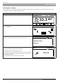
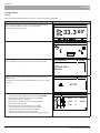
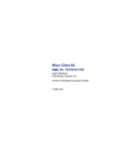
INSTALLATION & OPERATING MANUAL
PELLUX 100/20
PELLUX 100/30
AP
H
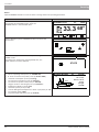
To Users
Information for the User
Information for the User
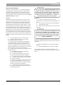
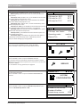
We recommend the following steps after the consumption of 300 kg of pellets:
1.
Check both ash pans and the combustion chamber. Empty the ash from them and clean, if necessary.
2.
Check the burner grate. If you find ash or deposits there, clean the grate (including air holes).
3.
Check the bottom of the pellet tray. If dust has accumulated there clean it.
4.
Remove the cleanout top cover, remove the turbulators and clean them (repeat this step every month).
5.
Use only high quality wood pellets of a diameter from 6 to 10 mm and a maximum length of 30 mm.
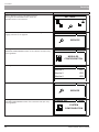
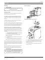
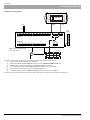
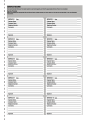
Dataplates are located on the right side of the boiler and under the cover of the front panel, also on the right side of the burner.
Symbol
Description
Symbol
Description
PELLUX 100/20
Type of boiler
PBMAX 20.1
Type of burner
IP 21
Degree of protection
IP 21
Degree of protection
Q
Range of electric power
Q
Power Rating
PQN
Power consumption at nominal power
Pmax
Maximal electrical power
PQmin
Power consumption at minimum power
Pmin
Minimal electrical power
Tmax
The maximum operating temperature
Tmax
The maximum operating temperature
PMS
Maximum working pressure
M
Weight
V
Water storage capacity
wood pellets
The required pellet size
class (EN 303-5) Boiler class according to the EN 303-5
wood pellet
Serial number
Basic fuel
The CE marking
The CE marking
Sign electro recycling - waste
Sign electro recycling - waste
Sign indicating the need to read the
manufacturer’s information
Sign indicating the need to read the
manufacturer’s information
“The Clean Air Act 1993 and Smoke Control Areas”
Under the Clean Air Act local authorities may declare the whole or part of the district of the authority to be a smoke control area. It is an offence to emit smoke from a chimney of a building, from
a furnace or from any fixed boiler if located in a designated smoke control area. It is also an offence to acquire an "unauthorised fuel" for use within a smoke control area unless it is used in an
"exempt" appliance ("exempted" from the controls which generally apply in the smoke control area).
The Secretary of State for Environment, Food and Rural Affairs has powers under the Act to authorise smokeless fuels or exempt appliances for use in smoke control areas in England.
In Scotland and Wales this power rests with Ministers in the devolved administrations for those countries. Separate legislation, the Clean Air (Northern Ireland) Order 1981, applies
in Northern Ireland. Therefore it is a requirement that fuels burnt or obtained for use in smoke control areas have been "authorised" in Regulations and that appliances used to burn
solid fuel in those areas (other than "authorised" fuels) have been exempted by an Order made and signed by the Secretary of State or Minister in the devolved administrations.
Further information on the requirements of the Clean Air Act can be found here : http://smokecontrol.defra.gov.uk/
Your local authority is responsible for implementing the Clean Air Act 1993 including designation and supervision of smoke control areas and you can contact them for details of Clean Air Act requirements.
Pellux 100/20 and Pellux 100/30 have been recommended as suitable for use in smoke control areas when burning wood pellets.
The product is not intended for use by persons with reduced physical fitness/mental efficiency or without experience and knowledge, if they are not supervised or instructed by a person
responsible for their safety. Operation of the product by children is strictly prohibited.
We reserve the right to make product design changes and changes in the manual.
©NIBE Energy Systems Limited 2014
2
PELLUX 100/20, PELLUX 100/30
To Users
Contents
To Users
Information for the User...........................................2
General..........................................................................4
Installation. ..................................................................5
Control panel...............................................................6
Control Panel Features......................................................... 6
Start-Up and Shutdown........................................................ 7
Control.................................................................................. 8
Simple Menu........................................................................ 9
Heating........................................................................ 11
General............................................................................... 11
Basic Modes of Operation of the Boiler............................. 11
Setting the Automatic Control of the Heating System........ 11
Basic parameters for Automatic Control of the Heating
System................................................................................ 11
Adjustment of the Factory Set Parameters........................ 11
Manual Temperature Change in the Rooms....................... 11
Maintenance and Troubleshooting. ..................... 12
General............................................................................... 12
Failure Causes and Corrective Measures............................ 13
To Installers
General Information for Installers. ............................ 14
Location of the Boiler......................................................... 14
Chimney – Requirements................................................... 14
Pellet – Requirements........................................................ 14
Distance to Walls................................................................ 15
Installation.......................................................................... 15
Connection to the System........................................... 16
Electrical Connections.................................................... 17
Connection......................................................................... 17
Internal Overvoltage Protection......................................... 17
Control Panel Connection................................................... 17
Direct Connection of Devices............................................. 18
Burner Connection............................................................. 19
External Temperature Sensor Connection.......................... 19
Heating Medium Temperature Sensor............................... 19
External Control.................................................................. 19
Tables of the Sensor Resistances........................................ 19
Boiler installation. .................................................... 20
Burner................................................................................ 20
PELLUX 100/20, PELLUX 100/30
Fuel Tank and Screw Feeder............................................... 20
Other Types of Fuel Dispensers.......................................... 20
Draught Regulator.............................................................. 21
Boiler Regulator Settings.................................................... 22
Burner Deafult Settings...................................................... 24
Servicing...................................................................... 25
Service Menu...................................................................... 25
Extended Menu.................................................................. 32
Service Settings.................................................................. 39
Alarm Codes....................................................................... 43
Example of Time Programming.......................................... 44
Connection of Optional Accessories................................... 45
Boiler and Burner Temperature Limiters............................ 56
Cleaning.............................................................................. 57
Wiring Diagrams. ...................................................... 59
Boiler.................................................................................. 59
Burner................................................................................ 60
Location of Components......................................... 61
Boiler.................................................................................. 61
Burner................................................................................ 62
Electrical Components........................................................ 63
Dimensions................................................................. 64
Quick Start Guide...................................................... 65
Standard Start-Up Without Oxygen Metering.................... 65
Procedure in the Case of Pellet Jamming........................... 66
Check of Settings................................................................ 66
Measuring Parameters Without the Exhaust Fan............... 66
Measuring Parameters with the Exhaust Fan
Installed/Switched ON........................................................ 66
Specifications............................................................. 67
Accessories Provided and Optional...................... 68
Connection of Modules........................................... 69
Lambda Probe.................................................................... 69
Weather Sensor.................................................................. 69
Hot Water Circulating Pump . ............................................ 70
Exhaust Fan........................................................................ 71
Installation of the Exhaust Fan........................................... 72
Declaration of conformity.................................................. 73
Commissioning Report for Biomass Boilers........ 74
PELLUX 100 Boiler Complaint Protocol...................... 81
3
To Users
General
General
Thank you for your confidence in us and our product, we also congratulate you on your choice of the PELLUX 100 boiler. It is
a high quality universal boiler, designed and manufactured by:
NIBE Energy Systems Limited
Unit 3c, Broom Business Park, Bridge Way
S41 9QG Chesterfield
Tel: +44 (0)845 095 1200
Fax: +44 (0)845 095 1201
In order to achieve the highest efficiency and safe working conditions, please read this Installation & Operating Manual carefully and comply with the recommendations and observations contained in it.
The PELLUX 100 boiler is designed to operate in open or closed systems. Please note that the system has to be protected in
accordance with the applicable regulations. For the boilers operating in an open and closed systems, protection of the system
must be in accordance with local regulations. PELLUX 100 boiler’s can be used in residential single and multi-family buildings,
guest houses, department stores, etc.
The PELLUX 100 boiler fitted with PBMAX burner is a device with high energy efficiency, up to 92 %, a significant functionality
and modern design. The design of the product refers to the long tradition and experience of the Swedish company NIBE in
the production of solid fuel fired boilers.
The basic boiler fuel is a modern, eco-friendly fuel in the form of wood pellets. A burner used in the unit ensures minimum
pellet consumption in relation to the thermal power received, resulting in fuel-efficient and comfort operation of the boiler.
The PELLUX 100 boiler has a compact design and operational solutions adapted to streamline its operation. With the enhanced electronic control, you can control many parameters of the unit, adjusting it to different installation conditions and individual needs.
This Manual applies to the PELLUX 100/20 boiler with the PBMAX 20 burner and the PELLUX 100/30 boiler with the
PBMAX 30 burner.
ATTENTION
PELLUX 100 boiler may only be installed by competent and qualified personnel, in accordance with applicable regulations, standards and manufacturer’s recommendations. Failure to follow these instructions may void your warranty.
ATTENTION
Use only original spare parts and accessories. NIBE takes no responsibility for damages resulting from the use of parts
from other manufacturers.
4
PELLUX 100/20, PELLUX 100/30
To Users
Installation
Installation
Intended Use
PELLUX 100 boiler is designed to heat homes and small
buildings.
Product Description
The boiler is designed to burn wood pellets.
Vertical convection system and the system of automatic
soot removal from the combustion tubes facilitate its
cleaning. This ensures a high and equal level of energy
efficiency. A large ash box facilitates the daily maintaining
of cleanliness and extends the time between subsequent
ash removals.
Burner installed in the PELLUX 100 boiler is provided with
automatic fuel feeding system. The boiler regulator is responsible for the process of the fuel supply and the burner
operation. Thanks to its modular design, it is possible to
expand the control system.
The system can be expanded up to: 16 heating circuits,
including 2 circuits for the hot water treatment, heating
system control with heat accumulation tank – a buffer
and control of the solar heating system operating with the
boiler.
Heating
The heating medium is discharged to the heating system through a nozzle located on the top of the boiler via
a 3-way valve. The three-way valve mixes the heating
medium flowing from the boiler with a colder medium
returning from the instalation, which maintains the preset
temperature in the instalation.
Hot Utility Water Treatment
The boiler allows connection of an external hot water heat
exchanger, and an external circulating pump of the hot
water system.
System Diagram
M
ATTENTION
This is a schematic representation only. The actual diagram of the system should be developed by an individual
qualified to do so, in compliance with all standards and regulations.
PELLUX 100/20, PELLUX 100/30
5
To Users
Control Panel
Control Panel
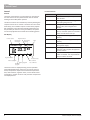
Control panel
Push buttons
ON/OFF switch
ON/OFF
ESC
TURNED OFF
Fr
12:35
33.3 65
ON
0
38
ENTER
INFO
Display
Status indicating LED
Two types of menu are available in the unit: a simple menu
and Home menu.
Simple menu – allows quick access to the basic control
panel features. You can access the simple menu by pushing
the UP or DOWN buttons on the main display.
Home menu – allows access to all control panel functionalities. You can access the Home menu by pushing the
ENTER button on the Home screen.
You can return to the Home screen from any screen by
pushing the ESC button several times.
Control Panel Features
Status Indicating LED
Green LED lights on
Control panel switched OFF
Green LED flashes
Control panel switched ON,
burner switched ON
Orange LED lights on
Control panel switched ON,
burner switched ON
Orange LED flashes
Burner works
Red LED lights on
An alarm exists, which
requires acknowledgment
Red LED flashes
Indicates an active alarm
ON/OFF. To switch the control panel ON or OFF,
press and hold the ON/OFF button for at least 3
sec.
Heating. Quick access to the complete configuration of the central heating settings.
Hot Water. Quick access to the complete configuration of the hot utility water settings.
INFO. It displays navigation data and descriptions
of the controlled parameters. Opens alarm list if
any active alarms exists.
ESC. Return a level up in the menu; skipping a
parameter change.
Up. Navigating the menus, increasing the value of
the parameter being edited. On the Home display,
entering the simple menu.
Down. Navigating the menus, decreasing the value of the parameter being edited. On the Home
display, entering the simple menu.
ENTER. Accessing menus. Acceptance of changes
in the value of the parameter being edited. Alarm
acknowledgement.
6
PELLUX 100/20, PELLUX 100/30
To Users
Control Panel
ATTENTION
Start-Up and Shutdown
The standard ignition process takes approx. 5 min.
If within that time the photocell does not detect a
flame the igniter retries this process 5 times. When
the fire still cannot be detected after 5 attempts, the
fire alarm procedure is initiated (No. 2 - No flame or
fuel) and the ignition process is interrupted.
The burner is fully automatic, i.e. it automatically ignites
and extinguishes, and does not require manual start-up
and adjustment during operation. The process of firing
pellets in the PBMAX burner is initiated by the boiler. For
more information about the settings, see the section Boiler
Regulator Settings on page 23.
Start-Up
Shutdown
Before the first start-up of the burner (or if you run out
of fuel), fill the auger with pellets. Fill the dispenser with
pellets, and then connect the feeder power cable to the
wall outlet, or run the Simple menu function FEED FUEL.
Complete filling of the feeder tube takes about 10 - 30 minutes (depending on the feeder model). When the pellets
reach the feeder outlet, leave the feeder running for approximately 2 minutes in order to optimize the feeder tube
filling and ensure uniform fuel supply. During the filling,
let the pellets fall into a container (e.g. a bucket) so that
you can throw them back into the dispenser. Then shift the
plug into the burner socket and install the corrugated hose
between the feeder and the burner (securing it with a hose
clamp).
1. Push the ON/OFF switch to start the boiler.
2. In order to start the burner, push and hold the ON/OFF button for 3 seconds.
3. Before turning the burner ON, two-step grate and heat exchanger cleaning process takes place.
(The default settings allows for adjustments in the range of 1-5.) Display of the control panel shows the status of CLEANING. The heat exchanger is cleaned for 30 seconds during the grate cleaning process.
4. Ignition process starts after the completion of the cleaning process.
A The FIRING UP command is displayed on the control panel display.
B The pellet is supplied to the burner for a preset time (70-80 sec by default, editable).
C The heater and air blower are switched ON.
D A photocell detects the flame and switches the electric heater OFF.
E Ignition process starts. Control panel display indicates the INCANDESCING command. This
procedure takes approx 5 mins within which the air blower speed increases gradually.
F At the end of the start-up procedure, the
boiler shifts to the preset program (threshold or modulating operation).
PELLUX 100/20, PELLUX 100/30
1. In order to shutdown the burner, do the
following: push and hold down the ON/OFF button for 3 sec.
2. The control panel display indicates TURNED OFF.
3. The pellet feeder stops.
4. The air blower operates until the no-flame status detection.
ATTENTION
The burner may still operate after switching the Control Panel OFF (damping a fire), depending on the
previous status. Do not interrupt this condition. If the
unit is to be disconnected from mains, wait until the
fire extinguishing process ends and the burner status
shifts to TURNED OFF.
You can also switch off only the burner alone, without switching the heating system OFF. In order to do this, proceed
as follows:
1. Enter the BURNER menu, and select SETTINGS option.
2. Select the Burner on option and set it to NO.
The shutdown sequence is initiated immediately. The
boiler regulator still controls the heating system circulating
pumps.
7
To Users
Control Panel
Control
Furnace statuses
General
Status
Description
The boiler Control Panel is a state-of-the-art microprocessor that controls not only the boiler but also the central
heating and hot utility water systems.
TURNED OFF
Burner does not operate. Operation is
not allowed.
CLEANING
Blowing of burner with strong jet air
and sliding the grate out.
FIRING UP
Fuel ignition. Administering an initial
dose of fuel, start of lighter and
blower.
INCANDESCING
After detecting the flame ignition
phase, air blower speed is increased in
order to heat the furnace up.
POWER 1
Stage 1 of the burning operation (MIN
power).
POWER 2
Stage 2 of the burning operation (MAX
power).
MODULATION
Burner operates with power modulation (power range).
BURNING OFF
Damping of the furnace. Air blower
operates until complete disappearance of the flame.
STOP
Burner does not operate but its operation is allowed. The required boiler
temp has been achieved.
The device controls the combustion process by feeding the
required amount of air and fuel. Thanks to the use of solid
state relays, the air blower output is continuously adjustable and thanks to the advanced operating algorithm and
the possibility of control of many parameters, the system
can be easily adjusted to the needs of the heating system.
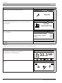
LCD Display
Furnace status
Day of the week
Boiler temp.
Boiler temp.
measured
setpoint
TURNED OFF
Time
Mo 12:05
33.3 60
OFF
0
Regulator status
38
Processor temp.
Furnace program
Heating program
Hot water
program
No. of alarms
not confirmed
The Home screen is displayed during normal operation
of the PELLUX 100 boiler, where you can see the furnace
status, temperature setpoint and measured temperature.
Also, date and time, regulator status, current boiler mode
of operation, number of alarms and processor temperature
are displayed here.
8
PELLUX 100/20, PELLUX 100/30
To Users
Control Panel
Simple Menu
Main Menu
BOILER TEMPERATURE
BOILER TEMPERATURE
HOT WATER TEMPERATURE
HOT WATER TEMPERATURE
HEAT NOW
HEAT NOW -YES/NO
HOT WATER PROGRAM
HOT WATER PROGRAM - time/manual/turn off
HEATING TEMPERATURE
HEATING TEMPERATURE
HEATING PROGRAM
HEATING PROGRAM - time/permanent/turn off/econom.
BURNER WORK
BURNER WORK - YES/NO
FEED FUEL
FEED FUEL - YES/NO
Navigation through the simple menu by clicking on UP and DOWN arrows. Value of any selected menu or submenu item can
be edited by pushing ENTER button.
Menu
Description
BOILER TEMPERATURE
65.3 70
M
HOT WATER TEMPERATURE
40.2 40
Displays the current furnace temp (large fonts) and furnace temp setpoint
(small fonts). ‘M’ means operation in manual mode. ‘A’ means operation in
the boiler auto temp mode.
After pushing ENTER, you can access the boiler setpoint setting.
Displays current hot water temp (large fonts) and temperature setpoint
(small fonts).
After pushing ENTER, you can access the hot utility water temp setpoint
setting.
This menu applies to the hot utility water circuit No. 1.
ATTENTION
Temperature is only displayed when a temp sensor is connected and
the hot utility water circuit activated in the menu settings.
HEAT NOW
YES
HOT WATER PROGRAM
manual
PELLUX 100/20, PELLUX 100/30
Heats up hot water to the comfort temp once regardless of the program
selected.
This menu applies to the hot utility water circuit No. 1.
Hot water program No. 1:
a) Time – acc. to the preset time intervals
b) Manual – comfort temperature is maintained regardless of time intervals
c) Turn off – heating OFF
This menu applies to the hot utility water circuit No. 1.
9
To Users
Control Panel
Menu
Description
HEATING TEMPERATURE
20.6 21.0
HEATING PROGRAM
permanent
BURNER WORK
YES
FEED FUEL
NO
10
Displays current temp in room No. 1 (large fonts) and setpoint value (small
fonts). After pushing ENTER, you can access the settings of the room temp
setpoint
This menu applies to the central heating circuit No. 1.
Program for heating circuit No. 1:
a) Time – according to the preset time intervals
b) Permanent – comfort temperature is maintained regardless of time
intervals
c) Turn off – heating OFF
d) Economy – temperature setpoint outside the heating period
This menu applies to the central heating circuit No. 1.
Burner operation allowed. If this option is deactivated, the Control Panel
controls the heating system, but does not fire the burner (even when temperature drops below the values, which would ignite the burner under normal
operation conditions)
Manual activation of the fuel feeder from the dispenser.
This feature is useful when running out of fuel from the dispenser, or at the
first start-up.
After refilling the dispenser with fuel, start the FEED FUEL option until the
fuel starts to discharge from the feeder tube to the burner
PELLUX 100/20, PELLUX 100/30
To Users
Heating
Heating
General
The internal temperature is dependent on several factors.
• The sun rays and heat emitted by humans and domestic appliances are sufficient to maintain the proper temperature in the house for a warmer part of the year.
• When it gets colder outside, the heating system should be turned on. The lower the outdoor
temperature the higher the temperature of radiators (if an outside temperature sensor and mixing valve
are installed.)
After entering the operating parameters of the system
from the control panel, the boiler starts automatic operation providing optimal and comfortable conditions of use.
Basic Modes of Operation of the Boiler
Controlling of heat production is based on the read out of
indications of two temperature sensors, external and internal (for the room temp). Both are optional and available as
accessories.
Outside Temperature Sensor
The boiler heats the water to the desired temperature
when the outside temperature drops to a preset value. This
is done automatically on the basis of information
obtained from the external sensor, and the sensor on the
lines supplying the radiators (a sensor behind the mixer,
one per circuit.)
The temperature sensor (installed on the outside North/
North-West facing wall of the house) detects the temperature variations, which makes the boiler able to respond
automatically to the drops in outside temperature before
the rooms in the house cool down.
Setting the Automatic Control of the Heating
System
In order to preset various temperatures, enter the
CENTRAL HEATING menu. You can select the desired values
in the SETTINGS and SERVICE tabs. For more detailed
information, see the Boiler Regulator Settings on page 23.
ATTENTION
Wait a day between successive settings to allow the
temperature to stabilize.
Basic Parameters for Auto Control of the
Heating System
Flow temperature of floor heating should be dependent on
the material of the floor. For floors made of wood, you can
increase the flow temperature. Adhere to the manufacturer’s recommendations.
Adjustment of the Factory Set Parameters
If the temperature setpoints in the rooms cannot be
obtained, adjustment of the preset parameters may be
required.
Manual Temperature Change in the Rooms
In order to change the room temperature temporarily or
permanently, select Comfortable temp, or Programme, or
Economical temp options in the CENTRAL HEATING/C.H.
SELECT/SETTINGS/ submenu (only if the room temp sensor
is installed, which is optional.)
ATTENTION
Temperature increase in the room can be limited by
a thermostat installed on the radiator or in underfloor
heating. In such a situation, you should increase its
setpoint.
Room Temperature Sensor (Option)
This sensor measures the temperature in the room and balances the flow temperature. If the temperature exceeds or
falls below the setpoint, the flow temperature is reduced
or increased by the mixing valve accordingly.
Manual control of the boiler working temperature (system without mixing valve)
The user can set the boiler to operate at a preset temperature, which translates directly to the temperature of
radiators.
PELLUX 100/20, PELLUX 100/30
11
To Users
Maintenance and Troubleshooting
Maintenance and Troubleshooting
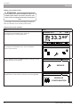
General
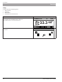
Alarm
The LED indicator light will light continuously red, if an
alarm which has not been acknowledged is present.
The LED indicator light will flash red, if an alarm which has
been acknowledged is still present.
If the chimney draught regulator is installed, close it
before cleaning. This is to prevent the spread of soot into
the boiler-room during cleaning. After cleaning, open the
regulator again. For detailed information, see Cleaning on
page 58.
ATTENTION
When you open the door of the combustion chamber,
the burner supply is automatically cut off. In order to
restart the burner, close the door carefully.
In order to check the alarm, enter the ALARMS menu,
where you can see the alarm code and description. For the
table with the alarm codes and descriptions, see page 44.
ON/OFF
ESC
TURNED OFF
Fr
12:35
33.3 65
ON
INFO
0
AP H
38
ENTER
Burner
In order to ensure the economical and ecological operation
of the system, the burner should be always optimized. Inspection and regulation should be carried out before each
heating season by a specialist in this field.
Circulating Pump
Even if the circulating pump is OFF for a longer period of
time, the computer controlling the boiler will run it twice a
day for 3 minutes. This is to prevent jamming of the pump
when starting the heating system.
Soot box and ash box are located under the combustion
chamber. Empty them at least once a month.
ATTENTION
You can only begin cleaning after damping a fire and
after the furnace temperature drops to the ambient
temp Use the adequate personal protective equipment when cleaning.
Soot and Ash Removal
Clean the chimney regularly at the intervals described in
the relevant fire regulations. The frequency of cleaning
of the boiler depends on the mode of its operation and
requires monitoring.
ATTENTION
Always disconnect the power supply when performing servicing or maintenance of the boiler and
burner.
The boiler features an automatic removal of soot from the
flues (smoke tubes), which facilitates maintaining cleanliness and efficiency of the boiler during its operation. In
order to achieve an optimal level of energy efficiency of the
work of the modern and properly adjusted pellet burner,
remove soot regularly from the other boiler surfaces
exposed to the flame (recommended: every 7 days). Clean
the furnace chamber of the boiler, flue gas turbulators and
flues at least once a month. It’s the user’s responsibility to
perform these operations and is not covered by warranty
services.
12
PELLUX 100/20, PELLUX 100/30
To Users
Maintenance and Troubleshooting
Failure Causes and Corrective Measures
In the event of malfunction or breakdown, please check
the following points.
ATTENTION
Boiler must be filled with water during start-up!
Low temperature in the rooms
• Faulty set/installed mixing valve
• Boiler’s temperature limiter has tripped. This may have tripped during transportation
• Air in the boiler or radiator system
• Shut-off valve in the heating system closed
• Circulating pump switched OFF or jammed. For more informaction, see Emergency start of the
circulating pump on page 13.
• Burner failure
• Circuit breaker tripped
• Max. flow temperature set too low
• Boiler is not switched ON
• Burner could be switched OFF by an external controller
• Stop the circulating pump
• Remove the air-vent screw. There can be a water
leakage from the pump
• Using a screwdriver, rotate the pump vanes by
hand
• Screw venting screw back into place
• Start the pump and check if it operates correctly
Usually, it is easier to start the pump when it is switched
ON. If you carry out the test with the circulating pump
ON, be prepared to the screwdriver jamming in the pump
impeller vanes.
High temperature in the rooms
• Heating automation settings incorrect
Resetting of temperature limiters in the burner and boiler
(STB)
The unit has two temperature limiters installed. One of
them is installed in the boiler and the other in the burner.
The temperature limiter in the burner (which should not be
confused with the STB in the boiler) cuts off supply to the
boiler and feeder when the temperature rises to 90 °C +/-5
°C.
The temperature limiter in the boiler (STB) cuts off supply
to the feeder and air blower and activates alarm when the
temperature rises to 99 °C -10 °C.
Before the burner and pellet feeder can be restarted, you
have to switch the temperature limiters ON manually. For
more details, see page 57.
Emergency start of the circulating pump
HEJSAN
IP 44
TF 110
Class H
M a x . 1 0 ba r
DK
Low temperature of the hot utility water
• Abnormally large hot water usage
• Wrong setpoint of the mixing valve
• Shut-off valves at the heat exchanger throttled or fully closed
• Boiler’s temperature limiter has tripped, this can occur during transportation
• Circulating pump set to lower speed or switched OFF
• Too large flow of the hot utility water
• Burner failure
• Burner could be switched OFF by an external controller
• Circuit breaker tripped
• Boiler is switched OFF
• Incorrect parameters set in the controller settings
• Shut-off valve in the cold water supply line to the heat exchanger throttled or closed
• Too low hot water temp setpoint
ATTENTION
P, ( W )
1 m( A )
45
0.20
65
0.30
90
0.40
Ty pe U P S 2 5 - 6 0
2 3 0 V50Hz
2.5uF
LEK
130
dor ka c l p
P/N:59526447
P C ; 0017N IB
Air-vent
screw
Luftningsskruv
If it is an electronic circulating pump and there is not any
automatic regulator of the return temp in the system installed, switch the auto mode in the pump OFF, which will
prolong the life of the boiler.
PELLUX 100/20, PELLUX 100/30
Tripping of the STB temperature limiter is a warning.
If the situation repeats, call the installer.
13
To Installers
General Information for Installers
General Information for Installers
Location of the Boiler
The boiler should be installed in accordance with local regulations. Installation of the boiler and pellet feeder on an
even and levelled concrete foundation with a height of at
least 5 cm and the edges protected by steel kerbs is recommended.
The boiler-room should have adequate air exchange. Correctly designed and constructed supply and exhaust ducts
should be made in the room. Boiler room must have air intake of an accumulative 200 cm2
Ventilation ducts shall be made of non-combustible materials. Adequate lighting, as far as possible covered by natural
light, should be ensured, but also the artificial lighting installation should be provided.
The floor must not be flammable or must otherwise be covered by a 0.7 mm thick steel sheet that extends 0.5 m out
from the boiler in each direction
Chimney – Requirements
Pellet – Requirements
The PBMAX 20/PBMAX 30 burners installed in the boiler
are designed to burn high quality wood pellets of 6-10 mm
diameter and maximum moisture of 10 %, according to
ISO 17225-2. We recommended Class A1 pellets. When using pellets of poorer quality, the boiler and the burner have
to be cleaned more frequently.
Use of any other fuels in the burner is prohibited.
Pellets must be stored in a dry and clean place.
ATTENTION
It is recommended to use high quality fuel, coming
from reliable sources. Fuel should have adequate
moisture and not contain mechanical impurities (e.g.
sand, stones, metal chips, etc.), which may deteriorate
the combustion process and cause failure of the unit.
ATTENTION
NIBE shall not be liable for any malfunction and improper
combustion resulting from the use of improper fuel.
ATTENTION
Ensure that the chimney cleaning is carried out in accordance with the procedures in force. If doubt, please contact a chimney sweep.
Chimney with the appropriate draught and with the right dimensions is a primary condition for the proper functioning
of the boiler. To a large extent, the productivity and efficiency of work depends on it. The boiler may only be connected
to the chimney with the appropriate draught (see Specifications page 68). It is important that the flue diameter (cross
section) and height are such, that no overpressure could be
created in the boiler and in the flue.
The PELLUX 100 boiler has a flue (circular cross section)
with an outside diameter of Ø133 mm. Flue must be tightly
connected (e.g. by means of a connection made of adequately thick sheet) to the flue pipe. The connection should
be made with a slope towards the boiler (recommended)
or in a straight boiler-chimney line. Do not reduce the diameter of the connection. Any bends and elbows increase
the resistance of flue gas flow, which may cause improper
operation of the boiler.
ATTENTION
Before installing, the flue pipe has to be tested and
approved by a chimney sweep.
14
PELLUX 100/20, PELLUX 100/30
To Installers
General Information for Installers
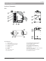
Distance to Walls
Set the boiler while maintaining the minimum distances to
the walls. When installing the unit, pay special attention to a
convenient access to the boiler, burner and chimney during
maintenance, cleaning and servicing.
B
Boiler
Feeder
A
A
C
The heating system of the closed layout shall meet the
requirements of local regulations and shall be fitted with
the system safety devices, such as:
• safety valve with the inlet and outlet pipe
• diaphragm expansion vessel
• expansion pipe
• protection of the heat source against exceeding the allowable temperature of the system water
• accessories: measuring and control devices, indicating at least the temperature of the system
water inflow and pressure in the system; fittings for automatic venting of the expansion pipe; blowdown fittings that allow draining of the expansion vessel water tank.
If the system has the open expansion vessel installed, then,
the difference in height between the highest positioned
radiator and the expansion vessel shall not be less than 2.5
m.
Fundation
Dimension
Distance [m]
A
0,2
B
0,5
C
1,5
Min 2,5 m
Minimum distances to the building walls, PELLUX
100/20, PELLUX 100/30.
ATTENTION
There is a risk of carbon monoxide poisoning, when
the boiler is installed in a not-adequately ventilated
room.
Installation
Comply with the applicable laws when installing the boiler.
The heating system and the boiler-room shall be made in
accordance with local regulations.
PELLUX 100/20, PELLUX 100/30
ATTENTION
Before connecting the boiler, flush the system to
remove small debris that can damage the boiler or
pump.
15
To Installers
Connection to the System
Connection to the System
The following diagrams show the connection of the PELLUX 100 boiler with hot utility water exchanger, multivalent vessel,
solar heating system, and a cascade of boilers.
PELLUX 100 boiler connected to hot water tank
M
PELLUX 100 boiler with multivalent vessel and solar heating system
T1
M
Can I/O 5
T3
Tbufg
T2
Tbufc
PELLUX 100 boiler in cascade arrangement
PELLUX
Can I/O 5 *
PELLUX
Can I/O 5
*
PELLUX
Can I/O 5
*
* additional accessory required
ATTENTION
These are schematic representations only. The actual diagrams of the system should be developed by an individual
qualified to do so, in compliance with all standards and regulations.
16
PELLUX 100/20, PELLUX 100/30
To Installers
Electrical Connections
Electrical Connections
Connection
The boiler is equipped with a regulator that controls the
burner and circulating pumps. Electrical connection of
external devices shall be made by an appropriately authorized and qualified electrician. Outputs suppying external
devices shall be connected in accordance with the relevant
indications.
• Power supply: 1/N/PE 230 V 50 Hz
• Outputs to external devices: 230 V/50Hz
For the detailed wiring diagram, see page 60.
ATTENTION
Only an appropriately authorized and qualified electrician may connect the electrical installation and perform its servicing. The electrical installation and cable
routing must be done in accordance with applicable
regulations.
ATTENTION
No other electrical equipment may be connected to
the boiler power supply line.
Internal Overvoltage Protection
Connect the sensors and actuators to the controller, as
required for the correct boiler operation, according to the
individual configuration. Some adjustments in the system
are required before the boiler start-up. For more details,
see Boiler Regulator Settings on page 23.
Connection of additional accessories sometimes requires
installation of additional modules.
Connection is to be made through additional CAN communication modules, allowing installation of additional
accessories, such as:
• up to 16 heating circuits
• two hot utility water treatment circuits
• buffer tank
• solar heating system
• exhaust fan
• Lambda probe
• GSM module
• Internet module
• room temperature sensor
• external temperature sensor
• wireless room temperature sensor
Connect the control panel to the CAN communication
module and power supply in accordance with the following
diagram.
Automatic controller of the heating system, pump, burner
and the system of supply for these devices are internally
protected by a 10 A miniature circuit breaker (MCB).
Control Panel Connection
ATTENTION
Power supply of the heating system must be disconnected when connecting the control panel.
L
H
GND
CAN
+12V
GND +12V
ATTENTION
Connection may only be performed with power supply disconnected and only by an individual appropriately authorized to do it.
ATTENTION
Always remember to install the termination at the
end of each CAN communication path. This is required
even when connecting a single communication
module.
PELLUX 100/20, PELLUX 100/30
17
To Installers
Electrical Connections
Direct Connection of Devices
The diagram below shows connection of module No. 6 and module for cleaning the grate to the control panel as well as the
accessories that do not require any additional modules.
ATTENTION
Never connect the PE conductor with neutral conductor (N).
ON/OFF
ESC
TURNED OFF
Fr
12:35
33.3 65
BURNER SAFETY CIRCUIT
ZPP
38
ON
INFO
M
4
TB
THW TCH TRT
TEXT Fotocell
CAN
6
MOTOR OUT 24V
- +
ENTER
ANALOG
IN1
IN2 IN3
IN4 IN5
IN6 IN7
IN8 IN9
IN10IN11
IN12 L
27 28 29 30 31 32 33 34 35 36 37 38 39 40 41 42 43 44
OUT GND
GND
GND
GND
GND
GND
H
12V
T 4 2 1
45 46 47
GND
GND
12V
PE
51 52
ADRES
GND
INPUTS
OUTPUTS
DO2
L1 L2 N
MOTOR CONTROL 230V
N L
1
230~
1
2
DO1
DO4
3
DO3
4
DO6
5
6
DO5
2 3
AO2
7
8
AO1
5
AO4
POWER
9 10 11 12 13 14 15 16 17 18
AO3
7
N1 N1 STBSTB N
8
9
N N
10
M
24 25 26
N
PE
N
L
1. Circulating pump, circuit No. 1
2. Open valve, circuit No. 1
3. Closed valve, circuit No. 1
4. Grate cleaning „-”
5. Igniter
6. Grate cleaning „+”
7. Fan
8. Boiler cleaning
9. Pellet feeder
10. Hot utility water supply pump
Item
Description
Designation
TB
Boiler temp sensor
IN1, GND
Burner safety circuit
Safety circuit (open door, burner overheating, wrong installation)
IN2, GND
THW
Hot utility water sensor
IN3, GND
TCH
Central heating sensor
IN4, GND
TRT
Room temp sensor
IN5, GND
TEXT
External temp sensor
IN11, GND
Foto
Brightness sensor in the burner
IN12, GND
ZPP
External control; burner operation allowed when closed
IN8, GND
GND
Electronic earth for the connection of sensors
GND
1 - CO 1 pump
Central heating circulating pump
DO1, N
2 – Opening of the CO 1 mixing valve
Opening of the central heating mixing valve
DO2, N
3 - Closing of the CO 1 mixing valve
Closing of the central heating mixing valve
DO3, N
4 – Cleaning of the + - grate
Grate cleaning control to the module
DO4, N
5 - Igniter
Igniter control
DO5, N
6 - Cleaning of the + - grate
Grate cleaning control
DO6, N
7 – Air blower
Burner air blower
AO1, N1
8 – Cleaning of heat exchanger
Cleaning of heat exchanger
AO2, N
9 – Dispenser feeder
Dispenser feeder, e.g. control of the feeder gear-motor
AO3, N1
10 – Hot utility water pump No. 1
Hot utility water circulating pump (circuit No. 1)
AO4, N
STB
Boiler temperature limiter (STB)
--
N
Neutral permanent
--
N1
Neutral, switching contact (by STB)
PE
Protective earth
18
PELLUX 100/20, PELLUX 100/30
To Installers
Electrical Connections
Burner Connection
Outdoor temperature sensor, CTZ-01
Connect the boiler’s power supply cable to the socket in
the burner.
Temperature
(°C)
Resistance
Min. (kΩ)
Resistance
Nom. (kΩ)
Resistance
Max. (kΩ)
External Temp Sensor Connection
-40
329.927
345.275
361.300
Install the external temperature sensor on the external
wall from the north, or north-west side in such a way that
the morning sun does not affect the temperature read
outs. The sensor is connected to the CAN communication
module with two-wire conductor. Minimum area of the
conductor is 0.4 mm2, and length max 50 m.
-30
173.153
180.031
187.164
-20
95.009
98.187
101.460
-10
54.247
55.745
57.278
0
32.101
32.813
33.537
10
19.621
19.956
20.296
Heating Medium Temp Sensor
20
12.351
12.504
12.657
The boiler is supplied with temperature sensor. Connect it
to the Cam communication module and install on the central heating circuit, directly behind the mixing valve. The
sensor must tightly fit to the circut and be well insulated.
25
9.900
10.000
10.100
30
7.952
8.050
8.148
40
5.227
5.314
5.401
50
3.517
3.589
3.662
60
2.418
2.476
2.536
70
1.695
1.743
1.791
80
1.211
1.249
1.288
90
0.881
0.911
0.943
100
0.651
0.675
0.701
110
0.488
0.508
0.529
120
0.372
0.388
0.405
External Control
Burner
Operation of the burner can be stopped by an external
signal (heat pump, external control system, etc.) from a
non-potential relay connected to the CAN communication
module, input No. IN8. For the wiring diagram, see page
18.
External circulating pump output
External circulating pump (e.g. hot utlity water pump) is
connected to the CAN communication module. Operation
of the pump depends upon output values from the boiler
controller. For the wiring diagram, see page 18.
Internal boiler temperature sensor, CT2a
Temperature
(°C)
Resistance
Min. (kΩ)
Resistance
Nom. (kΩ)
Resistance
Max. (kΩ)
3-way valve with actuator output
-40
329.927
345.275
361.300
Connect the 3-way valve for the heating medium temperature control to the CAN communication module. This
valve operates basing on the values entered on the control
panel. For the wiring diagram, see page 18.
-30
173.153
180.031
187.164
-20
95.009
98.187
101.460
-10
54.247
55.745
57.278
Tables of the Sensor Resistances
0
32.101
32.813
33.537
10
19.621
19.956
20.296
20
12.351
12.504
12.657
25
9.900
10.000
10.100
30
7.952
8.050
8.148
40
5.227
5.314
5.401
50
3.517
3.589
3.662
60
2.418
2.476
2.536
70
1.695
1.743
1.791
80
1.211
1.249
1.288
90
0.881
0.911
0.943
100
0.651
0.675
0.701
110
0.488
0.508
0.529
120
0.372
0.388
0.405
130
0.306
0.321
0.346
140
0.237
0.259
0.271
150
0.153
0.177
0.194
Internal temperature sensor, CTP-02 (room)
Temperature (°C)
Resistance (kΩ)
0
32.56
10
19.87
20
12.49
30
8.06
40
5.33
50
3.6
60
2.49
70
1.75
80
1.26
90
0.91
100
0.68
PELLUX 100/20, PELLUX 100/30
19
To Installers
Boiler Installation
Boiler Installation
ATTENTION
We recommend disconnecting the feeder pipe from
the burner before each opening of the boiler door.
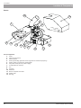
Burner
AP H
PBMAX burner is to be installed in the boiler door mounting opening. Install the burner using the knobs provided
with the burner. After installation, ensure that the burner
tightly fits to the boiler door.
ATTENTION
In case of improper installation of the burner, the
burner safety circuit alarm can be activated.
After installing the burner, do the following:
1. Install the corrugated hose on the burner feed pipe and secure it with a hose clamp.
2. Connect the electrical cables from the boiler to the burner and from the pellet feeder to the burner.
3. Switch the boiler regulator and ensure that the burner safety circuit alarm is not displayed.
Otherwise, check if the connection is correct and acknowledge the alarm.
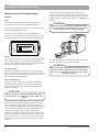
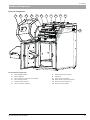
1. Set the fuel dispenser in a convenient place near the
boiler and remove the plug for the feeder pipe.
2. Install the pellet feeder in the fuel dispenser opening.
3. Secure the feeder pipe with clamps.
4. Adjust the length of the flexible hose. the hose must
not have any kinks in order to ensure free falling of the
pellets and avoid collection of sawdust.
5. Secure the flexible hose to the burner and fuel dispenser with hose clamps.
6. Before the first start-up of the burner (or if you run out
of fuel). Fill the dispenser with pellets, and then connect the feeder power cable to the wall outlet, or run
the function Feed fuel. Complete filling of the feeder
tube takes about 10 - 30 minutes (depending on the
feeder model).
7. When the pellets reach the feeder outlet, left the feeder
running for approx. 2 minutes in order to optimize the feeder tube filling and ensure uniform fuel supply. During
the filling, let the pellets fall into a container (e.g. a bucket)
so that you can throw them back into the dispenser.
8. Then shift the plug into the burner socket and install
corrugated hose between the feeder and the burner
(securing it with a hose clamp).
Other Types of Fuel Dispensers
The fuel dispenser should have a cover installed protecting
the pellets against moisture and the feeder components
against possible mechanical damage (e.g. due to entering
ahard object that might damage the feeder).
For the correct connection, see the drawing below.
Fuel Dispenser and Feeding Screw (Auger)
The pellet feeder supplies the burner with fuel coming
from the external fuel dispenser. Install the auger at an angle of 45 ° +/- 5°. During its operation, the auger installed
should supply approx. 10-11 kg/h of pellets for
PELLUX 100/20 and 12-13 kg/h for PELLUX 100/30.
Additional
opening
LE K
The pellet dispenser and feeder are available as optional
accessories. The recommended models are as follows:
•
ZP350 kit + PP12/PPL12 and ZP600 + PP15/PPL15
(pellet dispenser with auger)
•
PP15 & PP25 augers (1.5 m & 2.5 m)
Hose
clamps
that are dedicated to the PELLUX 100 boiler.
ATTENTION
To connect the burner with the pellet feeder only use
self-extinguishing corrugated hose provided. Using
charging lines of other type is not permitted!
20
ATTENTION
FUEL: PBMAX burner is installed in the boiler, is suitable only for burning high quality pellets, of 6 - 10 mm
diameter, 30 mm of length, and max 10% humidity.
We recommend DIN PLUS/EN A1 Pellet- according to
BS-EN 14961-2.
PELLUX 100/20, PELLUX 100/30
To Installers
Boiler Installation
Draught Regulator
ATTENTION
The chimney draught should be at least 18 Pa
(20 kW) and 22 Pa (30 kW). If such parameters
cannot be ensured, disassemble a couple of turbulators or use an exhaust fan.
Swing axle adjustment
After the installation, slightly loosen two lock screws and
turn the swing axle so, that it would be in horizontal position after closing the draught regulator. Retighten the lock
screws.
The chimney draught depends upon its diameter, height,
building location, wind conditions, external temperature,
boiler power output, flue gas temperature and soot accumulation in the chimney.
Most boilers operated currently are connected to older
types of chimneys. Sometimes, their diameters and insulation are not adequate for the new types of fuel.
Large fluctuations in draught can cause some disturbances
in the boiler combustion chamber operating conditions. In
order to minimize these deviations and the risk of damage
caused by condensation in the chimney, we recommend
the installation of a draught regulator in the boiler flue.
Lock screws
LEK
Draught regulator installation
Design of the draught regulator allows its installation in the
flues in any orientation: vertical, horizontal or inclined. The
controllers are installed on an adapter plate that replaces
the existing cleanout.
Draught control
Adjust draught with the throttle opened by holding the clip
with a weight and shifting it along the guide. Each shifting
of the weight of 2 mm corresponds to 1 Pa. These are
approximate values and you should measure them with a
micro pressure gauge.
X
By default, the controller is set to 10 Pa.
LEK
Correct adjustment should ensure smooth and even opening of the throttle when the boiler is switched OFF.
LEK
PELLUX 100/20, PELLUX 100/30
21
To Installers
Boiler Installation
Boiler Regulator Settings
The first boiler start-up requires enabling some features and entering some parameters. E.g. heating temperature sensor
should be activated and the flow temperature set.
Step
1. Push ENTER on the Home screen to enter the Home menu.
Menu
TURNED OFF
Fr
12:05
33.3 60
M
OFF
2. The Home menu contains the CENTRAL HEATING option. Open it
by pressing ENTER.
3. By means of UP and DOWN arrows, select the desired section.
4. After selecting the desired section, open with ENTER.
0
38
CENTRAL HEATING
C.H. SELECT
20:54
CIRCUIT NO: 1
Kitchen
5. By means of UP and DOWN arrows select the SERVICE option.
6. Open the SERVICE option by pressing ENTER.
The SERVICE menu is password-protected.
The password consists of the boiler temperature setpoint and the
letters EST (e.g. If the boiler tempearture is preset to 70 °C, then
the password is: 70EST).
For more details on using password, see page 26.
22
CH 1
20:54
SERVICE
PELLUX 100/20, PELLUX 100/30
To Installers
Boiler Installation
Step
7. By means of UP and DOWN arrows, select the following:
• MIN Tch pump, press ENTER and set the lowest possible flow
temp (+20 °C)
• CH temp for -20 °C, default: 70 °C, press ENTER and set the flow
temp at the external temp equal to -20 °C
• CH temp for 0 °C, default: 50 °C, press ENTER and set the flow
temp at the external temp equal to -0 °C
• CH temp for 10 °C, default: 40 °C, and set the flow temp at the
external temp equal to +10 °C
• CH temp corr. factor, press ENTER and set the flow temp change
value, when the external temp increments in 1 °C intervals
• Operating mode, press ENTER and select weather if the system
operates with the external temp sensor
• CH temp sensor, press ENTER and select YES if the system contains the flow temp sensor
• Permanent pump, press ENTER and select YES if the system is
controlled by an external temp sensor and flow temp sensor
Accept all above settings by pressing ENTER.
8. Press ESC repeatedly until you reach the Home menu.
9. By means of UP and DOWN arrows, select SETTINGS.
10. Press ENTER in order to open the SETTINGS submenu.
Menu
CH 1
CH temp for -20°C
70°C
CH temp for -0°C
50°C
CH temp for 10°C
40°C
CH 1
CH temp. corr. factor
Operating mode
5°C
weather
Manual Tch
35°C
SETTINGS
11. By means of UP and DOWN arrows, select SERVICE.
12. Press ENTER in order to open the SERVICE submenu.
The password consists of the boiler temperature setpoint and the
letters EST (e.g. If the boiler tempearture is preset to 70 °C, then the
password is: 70EST).
For more details on using password, see page 26.
TURNED OFF
13. By means of UP and DOWN arrows, select
SYSTEM CONFIGURATION.
14. Press ENTER in order to open the SYSTEM CONFIGURATION
submenu.
TURNED OFF
15. By means of UP and DOWN arrows, select Outside temp sensor.
16. Press ENTER in order to open the Outside temp sensor option.
17. Set the Outside temp sensor to YES.
TURNED OFF
20:54
Number of HW circuits
Number of buffers
Outside temp. sensor
1
0
YES
PELLUX 100/20, PELLUX 100/30
20:54
SERVICE
20:54
SYSTEM
CONFIGURATION
23
To Installers
Boiler Installation
Step
Menu
18. Ensure that the burner is installed. Using UP and DOWN arrows,
select BURNER.
19. Open this option by pressing ENTER.
20. Using UP and DOWN arrows, select SETTINGS.
21. Open this option by pressing ENTER.
BURNER
BURNER
20:54
SETTINGS
22. Set the BURNER to YES.
BURNER
Feed fuel now
20:54
NO
Burner on
YES
Fuel type
These are the minimum settings that are to be entered in
order to begin safe operation of the boiler.
Depending on the accessories connected to the boiler,
some other parameters require to be set and activated in
the controller, such as number of heating circuits, number
of hot utility water treatment circuits, buffer tank, solar
units etc.
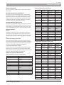
Burner Deafult Settings
Set the following parameters in the BURNER/SERVICE
menu.
Menu
20 kW
30 kW
Air MIN (30%)
9
Air MAX (100%)
40
Feeding MAX (100%)
7,6
10,2
Power MIN (FL2)
30
Power MAX (FL2)
100
Modulation type
FL2
FL2
Photo threshold
50
50
11,3 kg
13,5 kg
Test fuel mass
Fuel calorific value
5,3
Oxygen MIN (30%)
13
Oxygen MAX (100%)
8
Fuel pre-dose
24
pellets
70 s
100 s
Cleaning period
180 minutes
Cleaning cycles
2
PELLUX 100/20, PELLUX 100/30
To Installers
Servicing
Servicing
Service Menu
ATTENTION
Only authorized personnel may use the service menu!
Service menu is password-protected. The password consists of the boiler temperature setpoint and the letters EST.
If it’s in manual mode (letter M next to temperature) You
can read the temperature setpoint from the control panel
display. It is displayed in small digits next to the current
boiler temperature.
If it’s in auto mode (letter A next to temperature) Go to
BOILER/SETTINGS/Boiler temp set to check the temperature that has been set.
Example: If the boiler tempearture is preset to 70 °C, then
the password is: 70EST.
The password is only required in the service menu. After
approx. 10 min from pressing any button, the servicing
password is cancelled and you have to enter it again when
accessing the SERVICE menu.
Example of entering a password in the service menu:
Step
1. Begin from checking the temp setpoint on the Home screen. The
temperature must be ‘manual’ (M).
2. The temperature setpoint is displayed in small digits; here, it is
70 °C (default: 65 °C.)
3. Press ENTER to open the Home menu.
4. Use the UP and DOWN arrows to select the desired menu section.
ATTENTION
In the auto mode, check the temperature setpoint
(for the password) in the BOILER/SETTINGS/Boiler
temp set menu.
Menu
TURNED OFF
20:54
65.3
70M
Temperature setpoint
5. After selecting the desired menu section, e.g. SETTINGS, press
ENTER to open the desired section of the submenu.
6. Use the UP and DOWN arrows to select the SERVICE section.
7. Open the submenu by pressing ENTER.
SETTINGS
TURNED OFF
20:54
SERVICE
PELLUX 100/20, PELLUX 100/30
25
To Installers
Servicing
8. Using the UP and DOWN arrows, enter the password and confirm it
with ENTER.
(Password = boiler temperature setpoint + EST. Password example:
70EST.)
TURNED OFF
20:54
Password
*****
A B C D E F G H I J K L M
9. After you enter the correct password, the SETTINGS/SERVICE screen
is displayed.
10. Press ENTER and open a tab.
TURNED OFF
20:54
SERVICE
For the detailed information on menus and their contents,
see Extended Menu on page 33.
You can navigate the menu using the UP and DOWN
arrows.
Home Menu
Main menu
CENTRAL HEATING
HOT WATER*
BUFFER*
BOILER
SETTINGS
BURNER
ALARMS
SOLAR*
INFO
*Optional accessories required
26
PELLUX 100/20, PELLUX 100/30
To Installers
Servicing
Heating
CENTRAL HEATING
C.H. SELECT
STATE
State overview
SETTINGS
Comfortable temp
Programme
Economical temp
TIME PROG.
Time programme settings
SERVICE
Password
Comf. MAX pump temp
Econ. MAX pump temp
MIN Tch pump
Source
Temperature MAX
Mixer time
Hot water priority
Pump test
Mixer test
Circ. name
CH temp for -20 °C
CH temp for 0 °C
CH temp for 10 °C
CH temp corr. factor
Operating mode
Manual Tch
Room temp sensor
CH temp sensor
Permanent pump
PELLUX 100/20, PELLUX 100/30
27
To Installers
Servicing
Utility Water
HOT WATER*
H.W. SELECT
STATE
State overview
SETTINGS
Comfortable temp
Programme
Heat now
Hysteresis
Economical temp
TIME PROG.
Time programme settings
SERVICE
Password
Source delta
Source
Temperature MAX
Delta MIN temp
Pump test
Circ. name
Buffer
BUFFER*
BUFFER 1
STATE
State overview
SETTINGS
Upper set temperature
Lower set temperature
Programme
TIME PROG.
Time programme settings
SERVICE
Password
Minimal pump temp
Auto upper temp
*This feature requires optional accessory and activation
28
PELLUX 100/20, PELLUX 100/30
To Installers
Servicing
Boiler
BOILER
STATE
State overview
SETTINGS
Boiler temp set
SERVICE
Password
MIN pump temp
Mode
Hysteresis
MIN return temp
Return mixer time
Boiler pump test
Return mixer test
Heat Ex. clean begin t.
Heat Ex. clean end time
HeatEx. clean. out.test
Settings
SETTINGS
TIME AND DATA
Time and date settings
LANGUAGE
Choice of language
GENERAL SETTINGS
Alarm buzzer
SERVICE
Password
MODULES CONFIGURATION
Module 0
Module 1
Module 2
Module 3
Module 4
Module 5
Module 6
Module 7
Module Lambda
SYSTEM CONFIGURATION
Number of CH circuits
Number of HW circuits
Number of buffers
Outside temp sensor
Return temp sensor
Solars
Blower control
Blower with Hall
RESTORE FACTORY SETTINGS
PELLUX 100/20, PELLUX 100/30
Save changes?
29
To Installers
Servicing
Burner
BURNER
STATE
State overview
SETTINGS
Feed fuel now
Burner on
Fuel type
SERVICE
Password
Air MIN (30%)
Air MAX (100%)
Feeding MAX (100%)
Power MIN (FL2)
Power MAX (FL2)
Modulation type
Photo threshold
Igniter test
Storage feeder test
Blower test
Test fuel mass
Fuel calorific value
Lambda control
Oxygen MIN (30%)
Oxygen MAX (100%)
Fuel pre-dose
Cleaning period
Cleaning cycles
Exhaust fan
Grid cleaning test
Grid silent cleaning
30
PELLUX 100/20, PELLUX 100/30
To Installers
Servicing
Alarm
Alarms
Alarms list (displays 20 most recent alarms)
Solar
SOLAR*
STATE
State overview
SETTINGS
Turn on delta
Turn off delta
SERVICE
Password
Schematic
Flow [l/min]
Fluid specific heat
MAX HW temp
Solar alarm temp MAX
Solar alarm temp min
Solar pump test
*This feature requires optional accessory and activation
Info
INFO
Information on the current software version
PELLUX 100/20, PELLUX 100/30
31
To Installers
Servicing
Extended Menu
Heating
Open the CENTRAL HEATING menu to check or change the heating parameters.
Step
1. Press ENTER in the Home menu to open the extended menu.
2. Use UP and DOWN arrows to select the CENTRAL
HEATING submenu in the menu.
Menu
TURNED OFF
Fr
33.3 60
M
OFF
3. Press ENTER to open the CENTRAL HEATING submenu.
4. Use UP and DOWN arrows to select the desired section.
5. Press ENTER to open the submenu of the section selected.
12:05
0
38
CENTRAL HEATING
C.H. SELECT
20:54
CIRCUIT NO: 1
Kitchen
6. Here, you can select various options by means of the UP and
DOWN arrows.
7. Confirm your selection by pressing ENTER; here, it is the STATE
submenu.
CH 1
8. You can check the following parameters:
• Circuit number (on pic CH 1) and name (on pic KITCHEN)
• Measured (on pic 22.1 °C) and preset (on pic 21.0)
temperatures for a room/section
• Measured (on pic 44.1 °C) and preset (on pic 43.0)
temperatures for radiators.
• Measured external temperature (on pic -7.5 °C)
• Time of operation of the mixing valve (on pic 10)
• Heat source temperature setpoint (on pic 43)
• Indication of operation of the mixing valve
• Indication of operation of the central heating system pump
CH 1
32
20:54
STATE
KITCHEN
22.1
44.1
-7.5
43
10
˚C
˚C
˚C
21.0
43.0
PELLUX 100/20, PELLUX 100/30
To Installers
Servicing
Heating Settings
Feature
Description
Feature
Description
Comfortable temp
Temperature setpoint in the
room within the heating
period.
CH temp for 10 °C
Point on the heating curve
for the external temp equal
to 10 °C.
Programme
1. Time – operation acc. to
the preset time intervals.
2. Permanent – the setpoint
comfort temperature is
maintained all the time,
regardless of the set time
intervals.
3. Turn off – switches the
heating OFF.
4. Econom. – economic
temperature is maintained
in the rooms all the time.
CH temp corr. factor
Central heating temp setpoint correction in relation
to the room temp setpoint
per each 1°C. Example: if
the correction factor is set
to 6 °C, the temp setpoint
for a room is 20 °C, and
temp measured in the
room is 20.5 °C, then the
CH calculated temp will be
decreased of 3 °C.
Economical temp
Desired temperature in the
room outside the
period of heating.
Operating mode
Sets mode of the CH
temperature presetting;
manual – the CH temp is set
manually;
weather – the CH temp is
calculated from the heating
curve.
Manual Tch
CH temperature setpoint
when the mode of operation is set to Manual.
Room temp sensor
Indicates whether the internal sensor is used in the
system.
CH temp sensor
Indicates whether the central heating sensor is used
in the system.
Permanent pump
Yes – the pump starts after
the room temp setpoint is
reached. The CH calculated
temp is decreased (only if
the internal and CH sensors
are used).
No – the pump stops after
the room temp setpoint is
reached.
Service Heating Settings
Feature
Description
Comf. MAX pump temp
Maximum external temperature at which the circulating pump operates in the
comfort temp mode.
Econ. MAX pump temp
Maximum external temperature at which the circulating pump operates in the
economic temp mode.
MIN Tch pump
Minimum calculated central
heating temp at which the
CH circulating pump can
operate.
Source
Specifies the source of power for the central heating
circuit.
Temperature MAX
Maximum calculated temp
for the CH system.
Mixer time
Time of full opening of the
mixing valve.
Hot water priority
Hot utility water priority for
a given CH circuit. When
heating HUW, the CH pump
does not operate.
Pump test
Starts the circulating pump
regardless of other settings.
Mixer test
Activates the mixing valve
actuator regardless of other
settings.
Circ. name
Gives a name for the
central heating circuit.
CH temp for -20 °C
Point on the heating curve
for the external temp equal
to -20 °C.
CH temp for 0 °C
Point on the heating curve
for the external temp equal
to 0 °C.
PELLUX 100/20, PELLUX 100/30
33
To Installers
Servicing
Utility Water
In order to check the hot utility water parameters, open the HOT WATER submenu.
Step
1. Press ENTER in the Home menu to open the extended menu.
2. Using the UP and DOWN arrows, select the HOT WATER section in
the extended menu.
Menu
TURNED OFF
Fr
33.3 60
M
OFF
3. Press ENTER to open the HOT WATER submenu.
4. Using the UP and DOWN arrows, select the desired
section.
5. Press ENTER to open the section selected.
12:05
0
38
HOT WATER
H.W. SELECT
20:54
H.W. NO:1
BATHROOM 1
6. In this menu, you can select various options using the UP and
DOWN arrows.
7. Confirm your selection by pressing ENTER; here, the
STATE submenu has been selected.
HW 1
8. You can check the following parameters:
• Circuit number (on pic HW 1) and name (BATHROOM 1)
• Hot utility water temperature setpoint (on pic 50)
• Hot utility water measured temperature (on pic 45)
• Heat source temperature setpoint (on pic 60)
• Indication of operation of the hot utility water
circulating pump (operating when symbol is flashing).
HW 1
34
20:54
STATE
BATHROOM 1
45.0 50
PELLUX 100/20, PELLUX 100/30
To Installers
Servicing
Hot Utility Water Settings
Feature
Description
Comfortable temp
Hot utility water temp
setpoint within the heating
period.
Programme
1. Time - operation acc. to
the preset time intervals.
2. Manual - the setpoint
comfort temperature is
maintained all the time,
regardless of the set time
intervals.
3. Turn off – switches the
heating OFF.
Heat now
Heats up hot water once
up to the comfort temp
regardless of the program
selected.
Hysteresis
Value of which the HUW
temp can decrease.
Economical temp
HUW temp setpoint outside
the heating period.
Hot Utility Water Service Settings
Feature
Description
Source delta
Source temp increase
in relation to the HUW
temp setpoint throughout
heating period. Mode of
operation.
Source
Sets the HUW heating
source.
Temperature MAX
Maximum hot utility water
temperature.
Delta MIN temp
Minimum temp difference
between the source and
HUW at which pumps can
operate.
Pump test
Starts the circulating pump
regardless of other settings.
Circ. name
Gives a name to the HUW
circuit.
PELLUX 100/20, PELLUX 100/30
35
To Installers
Servicing
Boiler
Boiler operation statistics for the last 24 hours.
Step
1. Press ENTER in the Home menu to open the extended menu.
2. Using the UP and DOWN arrows, select the
BOILER section in the extended menu.
Menu
TURNED OFF
Fr
M
60
33.3
OFF
0
3. Press ENTER to open the BOILER submenu.
4. In this menu, you can select various options using the UP and
DOWN arrows.
5. Confirm your selection by pressing ENTER; here, the
STATE submenu has been selected.
6. You can check the following parameters:
• Operating status (last 24 h)
• No. of hours
• Boiler temp within the last two hours
• % of the burner power
• Average power
38
BOILER
BOILER
12:35
STATE
TURNED OFF
6
Fr
20:54
4
90
60
30
100
20
1h
36
12:05
1h
PELLUX 100/20, PELLUX 100/30
To Installers
Servicing
Boiler Settings
Feature
Description
Boiler temp set
The heating medium temp,
which will be maintained
by the regulator. This menu
is only active in the continuous mode of operation.
Boiler service settings
Feature
Description
MIN pump temp
Temp above which the regulator can start pumps.
Mode
1. Auto – the temp set in
auto mode.
2. Permanent – the temp
is maintained all the time/
preset by the user.
Hysteresis
The boiler temp has to
decrease of this value from
the temp setpoint in order
to start the burner.
MIN return temp
Minimum temp of the heating medium returning to
the boiler.*
Return mixer time
Sets time of full opening of
the return mixing valve.
Boiler pump test
Starts the boiler pump
regardless of other conditions.
Return mixer test
Manual activation of the
return mixing valve actuator regardless of other
conditions.
Heat Ex. clean begin t.
Sets time of the heat exchanger cleaning.
Heat Ex. clean end time
HeatEx. clean. out. test
Manual start of the test
cleaning of the heat exchanger.
* Optional accessories required
PELLUX 100/20, PELLUX 100/30
37
To Installers
Servicing
Settings
To check and set the following items:
• Date and time
• Language
• Alarm buzzer
• Connection of new accessories
Step
1. Press ENTER in the Home menu to open the extended menu.
2. Using the UP and DOWN arrows, select the
SETTINGS section in the extended menu
Menu
TURNED OFF
Fr
M
60
33.3
OFF
3. Press ENTER to open the SETTINGS submenu and select the desired item.
38
12:05
0
38
SETTINGS
PELLUX 100/20, PELLUX 100/30
To Installers
Servicing
Service Settings
System Configuration
Configuration of Modules
This menu allows configuration of the heating system
(hydraulic). Setting options depend upon number of the
extension modules set.
This menu allows configuration of the CAN bus.
ATTENTION
You have to configure the modules before entering
any new settings. For the configuration details, see
page 46.
In this menu, check the modules connected to the CAN.
Module
Description
Module No. 0
3 heating circuits No. 2, 3
& 4.
External temp sensor.
Module No. 1
3 heating circuits No. 5, 6
& 7.
Module No. 2
3 heating circuits No. 8, 9
& 10.
Module No. 3
3 heating circuits No. 11, 12
& 13.
Module No. 4
3 heating circuits No. 14, 15
& 16.
Module No. 5
Buffer.
Solar panels.
CWU No. 2.
Return temp sensor.
External temp sensor.
Module No. 6
Main boiler module.
Module No. 7
Additional exhaust fan
module.
Lambda module
Lambda probe module.
PELLUX 100/20, PELLUX 100/30
Feature
Description
Number of CH circuits
Sets No. of CH circuits in the
heating system.
Number of HW circuits
Sets No. of HUW circuits in
the heating system.
Number of buffers
Sets No. of buffers in the heating system (Module No. 5).
Outside temp sensor
Specifies whether the external temp sensor is installed
in the system (Module No.
0).
Return temp sensor
Specifies whether the return
temp sensor is installed in
the system (Module No. 5).
Solars
Specifies whether solar
panels are installed in the
system (Module No. 5).
Restoring the Factory Settings
This option allows you to restore the factory settings of the
regulator.
ATTENTION
All factory settings will be restored, which can cause
malfunctioning of the system. New configuration of
the regulator settings may be required after restoring
the factory settings.
39
To Installers
Servicing
Burner
Open the BURNER submenu in order to check or change the burner operating parameters.
Step
1. Press ENTER in the Home menu to open the extended menu.
2. Using the UP and DOWN arrows, select the
BURNER section in the extended menu.
Menu
TURNED OFF
Fr
M
60
33.3
OFF
0
3. Press ENTER to open the BURNER submenu and select the
desired item.
38
BURNER
4. In this menu, you can select various options using the UP and
DOWN arrows.
5. Confirm your selection by pressing ENTER; here, the
STATE submenu has been selected.
BURNER
6. You can check the following parameters:
• Burner operating status (in the pic TURNED OFF)
• % of the current burner power (in the pic Power=100 %)
• Total fuel consumption (in the pic 11.5 kg)
• Current fuel consumption (in the pic 2.6 kg/h)
• Current burner power in kW (in the pic 12.0 kW)
• Oxygen content in the flue gas (in the pic O2=8.0 %)
• Brightness of flame (in the pic 215)
• Air blower power (in the pic 13)
• Time of refilling the fuel dispenser in 20 sec. cycle (in the pic 7.6)
• Fan speed (in thepic 1600)
• Day of the week and time (in the pic Fr 20:54)
MODULATION
40
12:05
20:54
STATE
Fr
7.6
215
13
1600
20:54
O2 = 8.0 %
Power = 100 %
11.5 kg
2.6 kg/h
12.0 kW
PELLUX 100/20, PELLUX 100/30
To Installers
Servicing
Burner Settings
Feature
Description
Feature
Description
Feed fuel now
Activates continuous fuel
feeding, regardless of
settings.
Oxygen MAX (100%)
Oxygen setpoint at max
burner power, 100 %.
Burner on
Allows the regulator to start
the burner.
Fuel pre-dose
Time of fuel feeding during
the ignition process.
Fuel type
Sets the type of fuel used.
Cleaning period
Intervals between the subsequent burner cleaning.
Cleaning cycles
No. of the burner cleaning
cycles.
Burner Service Settings
Feature
Description
Exhaust fan**
Exhaust fan settings.
Air MIN (30%)
Minimum amount of air at
modulation, if the burner
power is 30 % or at power
threshold 1.
Grid cleaning test
Activation of the grate
cleaning test.
Grid silent cleaning
Grate cleaning only during
cleaning of the exchanger.
Air MAX (100%)
Maximum amount of air at
modulation, if the burner
power is 100 % or at power
threshold 2.
Feeding MAX (100%)
Maximum time of fuel feeding at modulation, if the
burner power is 100 %, per
each 20 sec.
Power MIN (FL2)
Minimum burner power at
modulation (power 1).
Power MAX (FL2)
Minimum burner power at
modulation (power 2).
Modulation type
Burner mode of operation,
modulated power (Fuzzy
Logic 2) or two power
stages (in steps). Power 2
outside the hysteresis and
power 1 within the
hysteresis.
Photo threshold
Brightness in the burner
above which the regulator
considers that the flame
exists.
Igniter test*
Starts the igniter for testing.
Heater feeder test*
(function not available)
Starts the fuel feeder for
testing.
Storage feeder test*
Starts the dispenser feeder
for testing.
Blower test*
Starts the air blower for
testing.
Test fuel mass
Amount of the fuel fed by
the dispenser feeder during
normal operation for 1
hour.
Fuel calorific value
Calorific value of the fuel
used (kWh/kg.)
Lambda control
Sets whether the regulator
should consider oxygen
content from the Lambda probe in the control
process.
Oxygen MIN (30%)
Oxygen setpoint at min
burner power, 30 %.
PELLUX 100/20, PELLUX 100/30
* Testing of the devices in the BURNER menu is only allowed when the regulator is in OFF mode.
** The exhaust fan has to be connected to the additional
module (Module No. 7).
41
To Installers
Servicing
Alarms
This menu contains the history of up to twenty alarms that occured during the controller operation.
Step
1. Press ENTER in the Home menu to open the extended menu.
2. Using the UP and DOWN arrows, select the ALARMS
section in the extended menu.
Menu
TURNED OFF
Fr
M
60
33.3
OFF
3. Press ENTER to open the ALARMS submenu.
4. Using the UP and DOWN arrows, select the alarm No.
5. Press Enter to confirm the selected alarm.
42
12:05
0
38
ALARMS
PELLUX 100/20, PELLUX 100/30
To Installers
Servicing
Alarm Codes
Main alarms
Code
Brief description
Possible cause
1
Processor overheating.
Repeated overheating of the boiler.
Boiler door has been opened during the boiler operation.
Poor chimney draught.
Improper setting of the oxygen dose for firing at MIN and MAX power.
2
No fire/fuel.
Ran out of fuel. Photocell failure. Too low, or too high fuel dose.
Extinction of flame.
3
Burner safety circuit.
Burner temp reached the max value.
Boiler door has been opened during the boiler operation.
Poorly mounted burner. Contaminated burner Poor chimney draught.
Improper setting of the oxygen dose for firing.
4
Boiler sensor shorting.
Sensor failure.
Sensor cable broken.
5
Break at boiler sensor.
Sensor failure.
Sensor cable broken.
6
Burner sensor shorting.
Sensor failure.
Sensor cable broken.
7
Break at burner sensor.
Sensor failure.
Sensor cable broken.
8
Boiler overheating.
Boiler temp has exceeded the max value.
9
Processor reset.
Controller probably damaged!
Power loss possible. Circulation pumps demage. Lack of heat reception.
10
STB.
--
11
Communication with Module No. 0. Problem with CAN bus or power supply.
12
Communication with Module No. 1. Problem with CAN bus or power supply.
13
Communication with Module No. 2. Problem with CAN bus or power supply.
14
Communication with Module No. 3. Problem with CAN bus or power supply.
15
Communication with Module No. 4. Problem with CAN bus or power supply.
16
Communication with Module No. 5. Problem with CAN bus or power supply.
17
Communication with Module No. 6. Problem with CAN bus or power supply.
18
Communication with Module No. 7. Problem with CAN bus or power supply.
19
HUW sensor shorting.
HUW sensor failure.
Sensor cable broken.
20
Break at HUW sensor
HUW sensor failure.
Sensor cable broken.
21
Room temp sensor shorting.
Room temp sensor failure.
Sensor cable broken.
22
Break at room temp sensor.
Room temp sensor failure.
Sensor cable broken.
23
Fire damping error.
Pellets accumulated in the flexible hose or burner. Feeder failure.
24
Communication with Lambda
module.
Problem with CAN bus or power supply.
25
Overheating of solar panels.
Pump or power cord failure.
26
Freezing of solar panels.
Pump or power cord failure.
37
Grate cleaning error.
Burner may not close or open the grate, which can be cuased by contaminated grate or loose screws. Grate cleaning modul damege.
38
Air blower error.
Air blower damaged, connection issues, power loss.
249
Temperature limiter (STB).
Boiler overheating. Reset the STB manually. Circulation pumps demage. Lack of heat reception.
PELLUX 100/20, PELLUX 100/30
43
To Installers
Servicing
Example of Time Programming
Info
This menu contains information on the unit, which may be
useful for the user, such as the controller software version.
ATTENTION
The comfort and economic temperatures may differ
from the temperatures set for various circuits. Therefore, to ensure the correct functioning of the schedule,
set a schedule for the comfort and economic temperatures.
INFO
KITCHEN
Setting Date and Time
The control panel contains a calendar and clock that allow
setting of various time-based features.
The controller has a battery (CR2032) installed that
supplies the clock in case of current decay.
44
0
6
Fr
12
18
24
0 :00
1. Press ENTER in the Home menu.
2. Using the UP and DOWN arrows, select the
CENTRAL HEATING submenu.
3. Press ENTER to open it.
4. Using the UP and DOWN arrows, select the
C.H SELECT submenu.
5. Press ENTER to open it.
6. Using the UP and DOWN arrows, select the
desired circuit (here: Kitchen).
7. Press ENTER to open it.
8. Using the UP and DOWN arrows, select the TIME PROG. submenu.
9. Press ENTER to open it.
10. Names of weekdays start flashing.
11. Using the UP and DOWN arrows, select the
desired weekday to be programmed.
12. Confirm your selection with ENTER.
13. Indicator above the time axis starts flashing.
14. Use the UP arrow to select time when the boiler starts heating + indicator jumps to the next time.
15. Use the DOWN arrow to select time when the boiler stops heating + indicator jumps to the next time.
16. After the completion of programming the
selected day, confirm your settings with ENTER.
17. After the confirmation or rejection of new
settings, the name of the weekday starts flashing
again.
18. Select the next weekday to be programmed with the UP and DOWN arrows.
19. In order to program all weekdays, repeat the steps from 6 to 18 above.
PELLUX 100/20, PELLUX 100/30
To Installers
Servicing
Connection of Optional Accessories
Connection of modules
All optional accessories need to be connected through
additional modules. Seven additional communication
modules are required to connect all optional accessories
available for the PELLUX 100 boiler.
The switches are numbered from 1 to 4. The switches No.
1, 2 and 3 assign a unique number for the module (i.e.
address). Switch No. 4 is a termination ending the address.
Value of switch No. 1 is 1, of switch No. 2 is 2, and of switch
No. 3 is 4. For example, if you wish to address Module No.
5, turn DIP-switches 1 and 3 ON and turn the DIP-switch 2 OFF.
1 2 4 T
Modules No. 0 - 4 are used for the heating circuits. Various
accessories can be connected to the Module No. 5, such
as solar panels, buffer, return temp sensor or external hot
utility water circulating pump.
1 2 3 4
ON
Example: for Module No. 5
Module No. 6 is a standard module, which is always installed in the boiler in order to ensure direct connection with
various features of the unit.
The Lambda module is factory set to control the Lambda
sensor only.
Individual optional accessories are connected to the proper
modules and then, via the CAN bus, to the Module No. 6
and boiler regulator.
Modules No. 0-5 should be installed in a separate box near
the boiler. Module No. 6 is inside the boiler.
ATTENTION
Only one module may be installed inside the boiler.
All the remaining modules should be installed in a separate box with the separate power supply.
In order to connect a module to an optional accessory, you
should assign it a new address using a DIP-switch (this does
not apply to the jumper in the Lambda module) to allow
the boiler to control the new device or use information
provided by it.
DIP-switch
Switch No.
(value)
Module No.
Description
1 (1) 2 (2) 3 (4)
OFF
OFF
OFF
Module No. 0
3 heating modules
No. 2, 3 & 4
ON
OFF
OFF
Module No. 1
3 heating modules
No. 5, 6 & 7
OFF
ON
OFF
Module No. 2
3 heating modules
No. 8, 9 & 10
ON
ON
OFF
Module No. 3
3 heating modules
No. 11, 12 & 13
OFF
OFF
ON
Module No. 4
3 heating modules
No. 14, 15 & 16
ON
OFF
ON
Module No. 5
Buffer, solar panels
& HUW No. 2. Return temp sensor
OFF
ON
ON
Module No. 6
(standard module)
Primary boiler
module installed
inside the boiler.
External temp
sensor
ON
ON
ON
Module No. 7
Auxiliary boiler
module
Lambda module Lambda probe
module
27 28 29 30 31 32 33 34 35 36 37 38 39 40 41 4243 44 45 46 47 48 49 50 51 52
ATTENTION
DIP-switch No. 4 is a termination!
1 2 3 4 5 6 7 8 9 10 11 12 13 14 15 16 17 18 19 20 21 22 23 24 25 26
PELLUX 100/20, PELLUX 100/30
The system requires to have two termination switches switched ON. One in the control panel, and one in the farthest
modul, or accessory that is installed. The Lambda module,
and internet module has a terminating jumper and does
not require a DIP-switch.
45
To Installers
Servicing
Master
Master
T=On
T=ON
I/O
00
T=Off
T=OFF
I/O
1
T=Off
T=OFF
I/O
2
T=Off
T=OFF
I/O
66
T=On
T=ON
Connection of Various Modules
IN1
IN2 IN3
IN4 IN5
IN6 IN7
IN8 IN9
IN10IN11
IN12 L
27 28 29 30 31 32 33 34 35 36 37 38 39 40 41 42 43 44
GND
GND
GND
GND
GND
H
T 4 2 1
45 46 47
GND
GND
12V
51 52
GND
ADRESS
INPUTS
OUTPUTS
DO2
1
2
DO1
DO4
3
DO3
4
DO6
5
DO5
6
AO2
7
AO1
8
AO4
POWER SUPPLY
9 10 11 12 13 14 15 16 17 18
AO3
N1 N1 STB STB N
Modules No. 0 - 4 are connected in the same way, but
support various circuits.
Module No. 0 – full control of 3 heating circuits with circulating pump and mixing valve; heating circuits No. 2, 3 &
4 – measurement of the external temperature
Module No. 1 – full control of 3 heating circuits with circulating pump and mixing valve; circuits No. 5, 6 & 7
N N
N
24 25 26
PE
N
L
Module No. 2 – full control of 3 heating circuits with circulating pump and mixing valve; circuits No. 8, 9 & 10.
Module No. 3 – full control of 3 heating circuits with circulating pump and mixing valve; circuits No. 11, 12 & 13.
Module No. 4 – full control of 3 heating circuits with circulating pump and mixing valve; circuits No. 14, 15 & 16.
No.
INPUT signal
No. OUTPUT signal
27
IN1 - CH temp sensor, circuits # 2, 5 & 8.*
1
DO1 - opening of CH mixing valve, circuits # 2, 5 & 8.*
28
GND.
2
DO2 - closing of CH mixing valve, circuits # 2, 5 & 8.*
29
IN2 - room temp sensor, circuits # 2, 5 & 8*
3
DO3 - opening of CH mixing valve, circuits # 3, 6 & 9.*
30
IN3 - CH temp sensor, circuits # 3, 6 & 9.*
4
DO4 - closing of CH mixing valve, circuits # 3, 6 & 9.*
31
GND.
5
DO5 - opening of CH mixing valve, circuits # 4, 7 & 10.*
32
IN4 - room temp sensor, circuit # 3.*
6
DO6 - closing of CH mixing valve, circuits # 4, 7 & 10.*
33
IN5 - CH temp sensor, circuits # 4, 7 & 10.
7
AO1 - CH pump output, circuits # 2, 5 & 8.*
34
GND.
8
AO2 - CH pump output, circuits # 3, 6 & 9.*
35
IN6 - room temp sensor, circuits # 4, 7 & 10.*
9
AO3 - CH pump output, circuits # 4, 7 & 10.*
36
IN7 - spare.
10
AO4 - spare.
37
GND.
38
IN8 - spare.
39
IN9 - spare.
40
GND.
41
IN10 - spare.
42
IN11 - Tzew – external temp sensor (only in Module # 0, comm for all CH circuits).
43
GND.
44
IN12 - spare.
* One circuit No. is per one extension module, e.g. circuit No. 2 is if for Module No. 0, circuit No. 5 is for Module No. 1, etc.
46
PELLUX 100/20, PELLUX 100/30
To Installers
Servicing
Module No. 5 is for the pump supplying the heat buffer – the pump that controls the mixing in the boiler together with mixing
valve, maintaining the minimum temperature of the boiler return water – control of solar panels – control of the hot utility
water pump.
No.
INPUT signal
No.
OUTPUT signal
27
IN1 – HUW sensor, circuit # 2.
1
DO1 – opening of return mixing valve (increases return flow from the boiler).
28
GND.
2
DO2 – closing of return mixing valve (decreases return
flow from the boiler and increases return flow temp).
29
IN2 – upper buffer temp sensor.
3
DO3 – spare.
30
IN3 – lower buffer temp sensor
4
DO4 – spare.
31
GDN.
5
DO5 – solar panel mixing valve, LHS.
32
IN4 – boiler return temp sensor
6
DO6 – solar panel mixing valve, RHS.
33
IN5 – spare
7
AO1 – HUW pump output, circuit No. 2.
34
GND.
8
AO2 – boiler pump output (buffer).
35
IN6 – T1 solar panel sensor
9
AO3 – spare.
36
IN7 – T2 solar panel sensor
10
AO4 – solar panel No. 1 output. Solar panel pump.
37
GND.
38
IN8 – T3 solar panel sensor
39
IN9 – T4 solar panel sensor
40
GND.
41
IN10 – spare
42
IN11 – spare
43
GND.
44
IN12 – spare
The Lambda module is already preset. By default, its
termination is OFF (jumper installed). Connect the Lambda
probe in the ‘plug and play’ manner.
Activation of the optional acessories
ATTENTION
Remember, in all additional modules always use dedicated temperature sensors or equivalent sensors.
Table with sensor resistances You will find at page 19
You can activate each of the optional accessories connected from the control panel.
Buffer
ATTENTION
The buffer tank is available as option. It can be controlled from the control panel when connected to the
heating system.
Activation of the buffer tank from the control panel
Step
1. Press ENTER in the Home menu to open the extended menu.
2. Using the UP and DOWN arrows, select the
SETTINGS section in the extended menu.
Menu
TURNED OFF
12:05
33.3 60
M
OFF
PELLUX 100/20, PELLUX 100/30
Fr
0
38
47
To Installers
Servicing
Step
Menu
3. Press ENTER to open the SETTINGS submenu.
4. Using the UP and DOWN arrows, select the
SERVICE section in the submenu.
5. Press ENTER to open the SERVICE submenu and log in. For the
logging instructions, see page 26.
SETTINGS
TURNED OFF
20:54
SERVICE
6. Using the UP and DOWN arrows, select the
MODULES CONFIGURATION section in the submenu and open it by
pressing ENTER.
TURNED OFF
20:54
MODULES
CONFIGURATION
7. Using the UP and DOWN arrows, select Module 5 and set it to YES.
8. Press ESC to return to the SERVICE submenu.
TURNED OFF
Module 4
20:54
NO
Module 5
YES
Module 6
YES
TURNED OFF
20:54
SERVICE
9. Using the UP and DOWN arrows, select the
SYSTEM CONFIGURATION section in the submenu and open it by
pressing ENTER.
48
TURNED OFF
20:54
SYSTEM
CONFIGURATION
PELLUX 100/20, PELLUX 100/30
To Installers
Servicing
Step
10. Using the UP and DOWN arrows, select Number of
buffers in the submenu and set it to 1.
Menu
TURNED OFF
20:54
Number of HW circuits
1
Number of buffers
1
Outside temp. sensor
YES
11. Now, the buffer tank is active and is controlled by the boiler controller.
Setting and checking the buffer tank parameters
In order to set and check the buffer tank parameters, open the BUFFER section of the menu.
Step
1. Press ENTER in the Home menu to open the extended menu.
2. Using the UP and DOWN arrows, select the
BUFFER section in the extended menu.
Menu
TURNED OFF
Fr
M
60
33.3
OFF
3. Press ENTER to open the BUFFER submenu and select the desired
option.
4. In this submenu, you can select various options with the UP and
DOWN arrows.
5. Confirm your selection with ENTER; here, it is the STATE submenu.
12:05
0
38
BUFFER
BUFFER 1
20:54
STATE
6. You can check the following parameters:
• Current and preset buffer tank temperatures in its upper part
(on pic 70.0)
• Current and preset buffer tank temperatures in its bottom part
(on pic 34.4)
• Buffer tank operating temperature (on pic 50M and 65)
• Return temperature (on pic 56)
• Heat source temperature (on pic 69)
• Indication of the CH circulating pump operation (operating when
symbol is flashing).
PELLUX 100/20, PELLUX 100/30
BUFFER
69
20:54
70.0
50 M
34.4
65
56
49
To Installers
Servicing
Buffer tank settings
Feature
Description
Upper set temperature
Charging process begins in
the upper part of the buffer
tank at this temp
Lower set temperature
Charging process ends in
the bottom part of the buffer tank at this temp
Programme
1. Time – operation acc. to
the preset time intervals.
2. Manual – buffer tank is
charged regardless of the
preset time intervals.
3. Turn off – buffer tank
charging OFF.
Buffer tank service settings
ATTENTION
Service settings of the buffer tank may only be set by
a qualified installer. Improper setting may cause damage to the system.
Feature
Description
Minimal pump temp
Minimum temp in the buffer tank upper part at which
the CH circulating pumps
may operate.
Auto upper temp
Sets whether the upper
buffer tank temp (min) is
to be set in manual or auto
modes. Auto mode sets the
temp on the basis of the
demand of other consumers of the buffer tank
energy.
50
PELLUX 100/20, PELLUX 100/30
To Installers
Servicing
Solar panels
ATTENTION
The solar unit is available as an option. The solar
panels connected to the boiler automatically can be
controlled from the boiler control panel level.
Solar unit activation
Step
1. Press ENTER in the Home menu to open the extended menu.
2. Using the UP and DOWN arrows, select the
SETTINGS section in the extended menu.
Menu
TURNED OFF
Fr
33.3 60
M
OFF
3. Press ENTER to open the SETTINGS submenu.
4. Using the UP and DOWN arrows, select the
SERVICE section in the submenu.
5. Press ENTER to open the SERVICE submenu and log in. For the
logging instructions, see page 26.
12:05
0
38
SETTINGS
TURNED OFF
20:54
SERVICE
6. Using the UP and DOWN arrows, select the
MODULES CONFIGURATION section in the submenu and open it by
pressing ENTER.
TURNED OFF
20:54
MODULES
CONFIGURATION
7. Using the UP and DOWN arrows, select Module 5 and set it to YES.
PELLUX 100/20, PELLUX 100/30
TURNED OFF
Module 4
20:54
NO
Module 5
YES
Module 6
YES
51
To Installers
Servicing
Step
8. Press ESC to return to the SERVICE submenu.
Menu
TURNED OFF
20:54
SERVICE
9. Using the UP and DOWN arrows, select the
SYSTEM CONFIGURATION section in the submenu and open it by
pressing ENTER.
TURNED OFF
10. Using the UP and DOWN arrows, select Solars in the submenu
and set it to YES.
TURNED OFF
Outside temp. sensor
20:54
YES
Return temp. sensor
Solars
YES
YES
20:54
SYSTEM
CONFIGURATION
11. Now the solar unit is active and is controlled by the boiler
controller.
Solar unit
In order to set and check the solar unit parameters, open the SOLAR submenu.
Step
1. Press ENTER in the Home menu to open the extended menu.
2. Using the UP and DOWN arrows, select the
SOLAR section in the extended menu.
Menu
TURNED OFF
Fr
33.3 60
M
OFF
3. Press ENTER to open the SERVICE submenu and select the desired
option.
52
12:05
0
38
SOLAR
PELLUX 100/20, PELLUX 100/30
To Installers
Servicing
Step
Menu
4. In this submenu, you can select various options with the UP and
DOWN arrows.
5. Confirm your selection with ENTER; here, it is the STATE submenu.
SOLAR
20:54
STATE
6. You can check the following parameters:
• Operating status of the solar panels (on pic STOP)
• Currently supplied power (on pic P=638 W)
• Flow rate in l/min (on pic F=4.0 l/min)
• Temp of the T1 solar panels (on pic 56.3)
• Temp of the T2 solar panels (on pic 46.9)
• Temp of the T3 solar panels (on pic 35.0)
• Pump operation status (operating when symbol is flashing)
Solar unit settings SOLAR
STOP
56.3
46.9
P=638W
F=4.0l/min
35.0
Solar unit service parameters
Features
Description
Turn on delta
Temp difference between
the solar collector and heated up water required to
start the solar pump.
Turn off delta
Temp difference between
the solar collector and heated up water required to
stop the solar pump.
PELLUX 100/20, PELLUX 100/30
ATTENTION
Service settings of the solar unit may only be set by a
qualified installer. Improper setting may cause damage to the system.
Feature
Description
Schematic
Specifies type of the solar
unit.
Flow [l/min]
Fluid flow rate in the solar
circuit during the pump
operation. This parameter
is required to calculate the
power of the solar
collectors.
Fluid specific heat
Specific heat of the fluid
used in the solar circuit
expressed in kJ/(kg * °C)
MAX HW temp
Maximum temp of the
water being heated up.
Solar alarm temp MAX
Maximum temp of the solar
collectors, above which the
safety system starts and
alarm is generated.
Solar alarm temp min
Minimum temp of the solar
collectors, below which the
safety system starts and
alarm is generated.
Solar pump test
Starts the solar unit pump,
regardless of other settings.
53
To Installers
Servicing
Settings of the Lambda module
ATTENTION
The Lambda probe module is available as option. The
Lambda probe module connected to the boiler automatics can be controlled from the boiler control panel
level.
Some changes in the control panel settings are required
after the installation of the Lambda probe module.
Lambda probe module activation
Step
1. Press ENTER in the Home menu to open the extended menu.
2. Using the UP and DOWN arrows, select the
SETTINGS section in the extended menu.
Menu
TURNED OFF
Fr
33.3 60
M
OFF
3. Press ENTER to open the SETTINGS submenu.
4. Using the UP and DOWN arrows, select the SERVICE
section in the submenu.
5. Press ENTER to open the SERVICE submenu and log in. For the
logging instructions, see page 26.
12:05
0
38
SETTINGS
TURNED OFF
20:54
SERVICE
6. Using the UP and DOWN arrows, select the MODULES CONFIGURATION section in the submenu and open it by pressing ENTER.
TURNED OFF
20:54
MODULES
CONFIGURATION
54
PELLUX 100/20, PELLUX 100/30
To Installers
Servicing
Step
Menu
7. Using the UP and DOWN arrows, select Module Lambda in the
submenu and set it to YES.
8. The, select the BURNER option. Enter the SERVICE submenu.
TURNED OFF
20:54
Module 6
YES
Module 7
NO
Module Lambda
YES
BURNER
20:54
SERVICE
9. Using the UP and DOWN arrows, select Lambda control in the
submenu and set it to YES.
BURNER
Test fuel mass
20:54
0.0
Fuel calorific value
0.0
Lambda control
YES
10. Now, the Lambda probe module is active.
ATTENTION
Remember about termination switches.
PELLUX 100/20, PELLUX 100/30
55
To Installers
Servicing
Boiler (STB) and Burner Temperature Limiters
Resetting of the boiler temperature limiter (STB)
5. Push the temperature limiter button on the
left side of the thermostat.
ATTENTION
Tripping of the boiler’s temp limiter warns of incorrect operation of the System, which requires investigation.
1. The STB temp limiter and door sensor are
available behind the boiler’s front panel.
Temperature limiter
Door opening
sensor
2. Disconnect the boiler power supply cables.
3. Open the boiler door and remove two screws retaining the front panel.
RESET button
(on the inside)
6. Reinstall the front panel.
7. Thoroughly close the boiler door. The door has a sensor installed, which prevents the boiler starting if the door is ajar.
8. Connect the boiler power supply cables.
9. Activate the control panel.
Resetting of the burner temperature limiter
This temperature limiter is available behind the burner
housing.
Photocell
Temp. limiter
Screws
4. The front panel is installed on clips. Pull it in your direction while taking care of the control panel wiring.
1. Disconnect the burner power supply cables.
2. Remove 4 screws fixing the burner housing.
3. Push the metal switch on the burner
temperature limiter.
4. Reinstall the burner housing.
5. Connect the power supply cables.
6. Activate the control panel.
ATTENTION
You may only reset the STB after the boiler cools
down. If the temperature remains high, the STB will
not reset. This applies both to the boiler STB and burner temp limiter.
56
PELLUX 100/20, PELLUX 100/30
To Installers
Servicing
Cleaning
Removing the trays
ATTENTION
Always disconnect the boiler power supply before its
inspection and cleaning!
Remove soot and ash from the boiler on a regular basis.
Cleaning procedure
Before cleaning, ensure that the boiler has cooled down
and is disconnected from the mains!
If installed, close the chimney draught regulator. This is
to prevent the spread of soot to the boiler-room during
cleaning. Don’t forget to open the regulator again after
cleaning.
AP H
Disassembly of the flue gas turbulators
The PELLUX 100 boiler cleaning is automatic; however, it
also requires regular cleaning by hand.
Automatic cleaning is performed by the motion of the turbulators in the convection section. This motion is forced by
the soot removal unit motor. Soot layer deposited on the
convection duct walls is scraped down to the soot tray.
Manual cleaning consists of pulling the soot removal
brush through the boiler convection ducts (smoke tubes)
after having removed the turbulators previously. The flue
gas turbulators need to be removed before cleaning the
convection ducts (smoke tubes). In order to do it, proceed
as follows:
• open the cleanout (by removing the outer knobs and using the inner ones as handles)
• pull away the movable arm under the pair of tur
bulators in such a way that they remain in their
uppermost positions
• remove the flue gas turbulators holding them by the connectors
• after removing the turbulators from the boiler flues, remove any contamination deposited on them
Soot removed from the boiler passes accumulates in the
soot tray at the bottom of the boiler, behind the ash pan. In
order to empty the soot tray, open the door first, remove
and empty the ash pan and finally, remove and empty the
soot tray.
AP H
1. Open the cleanout by removing the outer knobs
2. Pull away the movable arm under the pair of turbulators in such a way that they remain in their uppermost positions
3. Remove the flue gas turbulators holding them by the connectors
After the completion of cleaning, insert the ash pan and
soot tray to their original positions and close the door.
Reinstall the flue gas turbulators and close the cleanout.
ATTENTION
The ash may still contain smoldering fuel particles.
When emptying the ash, wear protective clothing and
store the ashes in a nonflammable container.
PELLUX 100/20, PELLUX 100/30
57
To Installers
Servicing
Feeder tube
Top fire grate
AP H
Cleaning
mechanism
Extraction of ash
APH
Flue
Scheduled maintenance
For user’s safety and proper operation of the burner, the
device shall be subjected to annual maintenance.
Combustion chamber
Ash box
Ceramic insert
Soot box
The figure above shows the areas requiring cleaning.
Cleaning of burner
In order to clean the burner manually, do the following
steps:
• begin the flame extinguishing procedure and wait until it ends up and the text TURNED OFF appears on the regulator
• disconnect the power supply and let the burner cool down in order to avoid burns
• clean the corrugated hose
• clean the feeder tube
• scrape the igniter plate and grate and clean holes in the grate
• remove the ash from the burner and boiler
58
Extinguish the flame and switch the boiler main switch OFF
when the grate is in its outer position (i.e. grate is extended) and then:
1. Remove the housing (see Fig. on page 57) and clean the flame sensor with a cloth and soft abrasive agent (such as toothpaste)
2. Clean the air blower vanes. You can clean them carefully with compressed air
3. Remove the grate sides and igniter plate and loosen the pipes of the igniter heating element
4. Clean the space behind the igniter plate and the grate
5. Reinstall all of the previously removed
components
6. Remove small particles from the pellet dispenser and feeder
7. Check the condition of the corrugated hose
8. Start the pellet feeder by inserting the plug into the burner’s socket, then go to Simple menu/FEED FUEL and set it to YES. It takes approx. 10-20 min to fill the feeder tube completely.
9. Adjust the burner
PELLUX 100/20, PELLUX 100/30
LV cable
PELLUX 100/20, PELLUX 100/30
Microswitch
C1 1,5uF
HV cable
brown
8
29
Tco
Temperature limiter
blue
18
white
(6) (5)
4 6 18
L1L2 N
- +
Induction motor + capacitor
13
14
Fire grate cleaning module
OUTGND
41 40
Plug + round socket
STB
M
25
26
N L
(2)
12V
GND
L
white
(4) (5)
51
52
45
46
47
H GND
(5)
(6)
(2)
(1)
(3)
(4)
(PE)
1 2 3 4 5 6 7 8 9 101112131415161718
Main module
PE N
L
5152
12V GND
242526
(1)
brown
black
272829303132333435 363738394041424344 454647
(3)
Control panel
L
H
GND
PE connector
white
brown
25
26
MCB
L
L
FP-250/5
Rocking breaker
N
N
C,047uF
Power supply 230V
To Installers
Wiring Diagrams
Wiring Diagrams
Boiler
59
To Installers
Wiring Diagrams
Burner
Housing earth
Heating
element
Socket
green-yellow
Fan
Wall sensor cable
green-yellow
Electric motor
green
black
white
brown
brown
blue
black
brown
blue
white
black
white
Photocell
blue
blue
black
white
brown
blue
brown
brown
white
grey
blue
green-yellow
Temperature limiter
blue
Microswitch
1
5
2
4
3
blue
Plug connector
Plug connector
60
PELLUX 100/20, PELLUX 100/30
To Installers
Location of Components
Location of Components
Boiler
10
1
2
15
3
16
9
4
17
6
7
8
18
14
19
11
12
20
13
21
List of components
1.
2.
3.
4.
6.
7.
8.
9.
10.
11.
Cleanout, male.
Smoke tube cleaning mechanism.
Convection ducts (smoke tubes).
Flue gas turbulators.
Soot box.
Ceramic insert.
Ash box.
Burner.
Circuit breaker, 10 A.
Cleanout cover.
PELLUX 100/20, PELLUX 100/30
12.
13.
14.
15.
16.
17.
18.
19.
20.
21.
CH heating water supply connection.
Boiler regulator (operator panel).
Main ON/OFF switch.
Throttle for burner supply lines.
Sight glass for burner flame checks.
Boiler door.
Auxiliary CH heating water supply connection.
Duct for cables, ID 26.
CH heating water return connection.
Blowdown connection.
61
To Installers
Location of Components
Burner
12
13
11
1
2
3
10
4
5
6
7
9
8
14
List of components
62
1.
2.
3.
4.
5.
6.
7.
8.
9.
10.
11.
12.
13.
Grate
Cleaning mechanism
Electric heater
Switch (protecting against the burner ignition if installed improperly)
Power outlet to connect the pellet feeder
HV power outlet (burner power supply)
LV outlet (burner control)
Fan
Actuator
Photocell
Burner temperature limiter
Feeder tube
Housing
PELLUX 100/20, PELLUX 100/30
To Installers
Location of Components
Electrical Components
1
2
3
4
5
6
7
8
9
10
11
12
List of electrical components
1.
2.
3.
4.
5.
6.
Main ON/OFF switch
Boiler regulator
Burner power supply and control cable
Door opening sensor
Grate cleaning module
Duct for electric cables LV
PELLUX 100/20, PELLUX 100/30
7.
8.
9.
10.
11.
12.
Boiler temperature limiter
Capacitor
Gear-motor connection
Boiler power supply connection
Duct for electric cables HV
Boiler primary module
63
To Installers
Dimensions
Dimensions
E
D
A
F
R25
B
C
R
O
J
O
H
P
N
M
G
L
K
I
R25(x3)
R15
PELLUX 100/20
A
B
C
D
E
G
H
I
64
PELLUX 100/30
942 mm
526 mm
597 mm
801 mm
595 mm
342 mm
1151 mm
350 mm
296 mm
PELLUX 100/20 PELLUX 100/30
J
K
L
M
N
O
P
R
120 mm
792 mm
710 mm
210 mm
65 mm
133 mm
128 mm
20-40 mm
133 mm ext.
PELLUX 100/20, PELLUX 100/30
To Installers
Quick Start Guide
Quick Start Guide
Standard Start-Up without Oxygen Metering
These are the basic start-up instructions. The unit requires
adjustment after the start-up. Perform the flue gas analysis,
if access to the chimney is difficult or any operation issues
arise (this option is not described here.)
Connect the chimney, without the draught regulator at the
beginning, unless there are some problems with differential/strong draught.
• Connect the electrical installation in accordance with the local regulations (with proper earthing and RCD)
• Install the flues in accordance with the
regulations in force and proper installation practices, with correctly dimensioned expansion vessel and protecting fittings
• Fill the boiler with water and vent the system well
• IMPORTANT: ensure that the burner is correctly tightened, and in particular its cover, when assembling the boiler
ATTENTION
Due to the requirements of BS EN 303-5 Class 5, the
gasket is very strong and you have to tighten it pretty
much the first few times. If this is not done, the boiler goes into alarm mode and a code 03 appears i.e.
the burner safety circuit. There are three factors that
may activate alarm: the door opening sensor, contact
between the cover and the burner, or actual burner
overheating when the bimetallic sensor at the pipe
elbow is switched OFF due to secondary combustion
(90 °C).
• Set Air MIN to 8 (on the right)
• Then, set Air MAX to 35
• Now, you have completed the main settings in the
menu
• Return to the Home page by pressing ESC several
times
• Switch the red ON/OFF button on the left hand side OFF and hold it for at east 3 sec until the ON text
appears in the lower left corner
After circa 15 min of operation: thoroughly check the chimney draught when the inspection window is open and at the
lowest power. ATTENTION: the area can be very hot. When
you move your hand gently over the sight glass opening, hot
air should not blow on your hand when the appliance is on.
If there is no draught, hot air escapes to the outside. Draught should be good when no hot air escapes to the outside
through the inspection window. To be sure that the draft is
good we recommend, however, draught and flue gas temperature measurement.
ATTENTION
We recommend the draught between 20-25 Pa (2.0
-2.5 mm HG) at 100% capacity, as long as the external
conditions allow it (depending on the weather conditions). If the sufficient draught cannot be achieved,
remove the central set of turbulators and repeat the
test. If the problem persists, you should improve conditions in the chimney, e.g. through the installation of
an air exhaust fan.
Flue gas temperature should neither drop below 110 °C nor
exceed 200 °C for the most of the boiler operation time.
Maintaining the high temperature at the bottom may be
difficult, in particular with the older chimneys. This means
the lower capacity of the boiler.
• Fuse and boiler ON/OFF switch are switched ON
• Press ENTER once
• Select BOILER using the UP and DOWN arrows
• Press ENTER to access the boiler menu
• Use the UP and DOWN arrows to select
SETTINGS
• Press ENTER to access the SETTINGS submenu
• Select the Boiler temp set and set it to min
65 °C. Press ENTER twice to confirm your setting (you can decrease the temp to 60 °C in the summer when the boiler is only used to heat up the hot utility water)
• Press ESC twice
• Use the UP and DOWN arrows to select the
BURNER option in the submenu and confirm your
selection with ENTER
• Go down with the arrow to the SERVICE option and press ENTER
• Enter the passoword (i.e. temp setpoint + letters
EST)
• Press ENTER again
PELLUX 100/20, PELLUX 100/30
65
To Installers
Quick Start Guide
Procedure in the Case of Pellet Jamming
Many customers are struggling with pellet jamming. Jams
should generally occur only at a very weak draught or too
low ventilation setting.
We have some proposals how to deal with the pellet jamming.
• Pellets are maybe too long. The max length is 35 mm.
• Pellets should have a compact consistency and should not crumble up when it pours through the fingers.
• Do not store pellets in too dry or too wet
conditions, since it critically changes its calorific value.
• Remove the ash from burning pellets from the ash pan, auger and flexible hose once or twice a year. Pay attention to avoid the accumulation of ash at the screw feeder motor.
• Length of the flexible hose is min 50 cm. It should be routed so, that pellets might not accumulate inside the hose.
• The screw feeder may not be inclined of more than 45° vertically downwards.
• Adjust the pellets sieve (mainly, by using the short hose provided). You can see the so called‚
pellets sieve’ consisting of 3 layers, when you
remove the burner and the cover. In the low models, you can cut the bottom sive away or remove it, but you should set the metering to 80 sec at the beginning (in the BURNER submenu.)
• Select the BURNER/Fuel pre-dose option. Then,
check whether two semicircular sockets in the plate are
covered with pellets at the burner ignition, otherwise,
increase pellet metering (up to 100 sec). Remove the pipe
elbow from the burner. If the centering plate is in the opening, push it completely to the boiler/burner head so, that
it is no longer in the opening.
If all the above conditions are met and pellets are still jamming, you should shift to another type of pellets.
Check of Settings
66
• Check the chimney draugt – it should be
between 20-25 Pa at 100 % load and approx. 5-10 Pa at 30 % load (manufacturer’s requirements are: 18 Pa at 100 % capacity). Boiler may be operated at
pressures from 15 -> 45 Pa. This value shall be
5-10 Pa at 100 % load when measured in the
inspection opening.
• Too high draught may cause some issues. If this is the case, install a throttle in the chimney/flue.
• Check the flue gas temperature on a regular basis. Consider the values above 200 °C as faulty and as the boiler malfunction. However, it is
sometimes necessary, if the chimney conditions are not good enough or installation of the exhaust fan is required. If the temperature is maintained below
110 °C, then high risk of soot formation exists, which forms peeling off overhangs at the final stage.
• Use proper measuring tools for the boiler
adjustments or when pellets jamming or other issues occur during the equipment operation. Sometimes, you have to find a compromise since the conditions in chimneys may vary significantly.
Measuring Parameters without the Exhaust Fan
Parameters at 100 % load:
• Draught 20-25 Pa (possibly 15-45 Pa)
• Temperature 130-180 °C (possibly 110-250 °C)
• CO (carbon monoxide) <500 ppm (it should be maintained below 1500 ppm and max 3000 ppm acc. to the requirements)
• OXYGEN 8-10 %
Parameters at 30 % load:
• Draught approx. 5 Pa (possibly 3-10 Pa)
• Temperature 100-150 °C (possibly 80-200 °C)
• CO (carbon monoxide) <1000 ppm (it should be maintained below 1500 ppm and max 3000 ppm acc. to the requirements)
• OXYGEN 12-15 %
Measuring Parameters with the Exhaust Fan
Installed/Switched ON
Parameters at 100 % load:
• Draught 12-15 Pa (possibly 10-30 Pa)
• Temperature 130-180 °C (possibly 110-250 °C)
• CO (carbon monoxide) <500 ppm (it should be maintained below 1500 ppm and max 3000 ppm acc. to the requirements)
• OXYGEN 8-10 %
Parameters at 30 % load:
• Draught approx. 2-3 Pa (possibly 1-10 Pa)
• Temperature 100-150 °C (possibly 80-200 °C)
• CO (carbon monoxide) <1000 ppm (it should be maintained below 1500 ppm and max 3000 ppm acc. to the requirements)
• OXYGEN 12-15 %
ATTENTION
Never allow overpressure in the boiler. You can check
this by opening the inspection opening at the boiler –
hot air must not escape from the inspection window.
PELLUX 100/20, PELLUX 100/30
To Installers
Specifications
Specifications
IP 21
PELLUX 100/20
PELLUX 100/30
Rated power
20 kW
30 kW
Net weight
202 kg
245 kg
60 l
70 l
Type
Water capacity
Power supply
230 V NAC 50 Hz
Boiler efficiency
90 - 92 %
Operating temp max
85 °C
Return temp min (at the boiler inlet)
60 °C
Flue gas temp
80 ÷ 150 °C
Noise level
Outlet
48 dB
ø133 mm ext. / ø125 mm int.
Pressure max
Flue gas draught required
0.25 MPa (2.5 bar)
18 ÷ 20 Pa
Length of combustion chamber
22 ÷ 25 Pa
320 mm
Degree of protection
IP 21
Chimney diameter
Ø150 mm
Chimney height (recommended)
6m
Power consumption in standby mode
13 W
Power consumption at nominal power
43 W
54 W
Power consumption at min power
20 W
26 W
42 kg/h
64 kg/h
Flue gas mass flow – at rated power
Flue gas mass flow – at min power
18 kg/h
28 kg/h
Pressure drop at the boiler – Δ10 °C
2 (1) mbar
6 (2) mbar
Pressure drop at the boiler – Δ20 °C
6 (3) mbar
17 (4) mbar
(1) at Q = 0,8 m3/h, (2) at Q = 1,3 m3/h, (3) at Q = 1,6 m3/h, (4) at Q = 2,5 m3/h
PBMAX20/30 Burner Specifications
Type
PBMAX 20
PBMAX 30
Burner capacity
6 ÷ 20 kW
9 ÷ 30 kW
Fuel
Wood pellets 6 ÷ 10 mm
Power supply
230V NAC 50 Hz
Electric power
40 W
Electric power at start-up
650 W
Degree of protection
Net weight
PELLUX 100/20, PELLUX 100/30
IP 21
14,5 kg
17 kg
67
To Installers
Accessories Provided and Optional
PELLUX 100 Boiler Equipment
Optional Accessories
Ramrod handle (1 pce)
CT2 temperature sensor, L=600 mm (2 pcs)
Chimney connection - vertical / cleanout (1 pce)
User’s Manual (1 pce)
PBMAX burner (1 pce)
Side pack kit (envelope)
• Draft regulator Tigex (1 pce)
• Round cleaning brush ø68 (1 pce)
• Gasket adapter - draught (1 pce)
• Plug 1/8” (1 pce)
• Draining Valve G15 (1 pce)
• Plug 3/8” (1 pce)
• Wing nut M8 (1 pce)
Pellets dispenser + feeder
ZP350
ZP600
VIDE GSM communications module
Wireless room temperature controller
CAN communications cable, 5.0 m
CAN communications cable, 0.45 m
CTP-02 room temperature controller
CAN 1/0 MC-1 expansion module
ML-2 CAN Lambda probe module assembly
Internet module
68
PELLUX 100/20, PELLUX 100/30
To Installers
Connection of Modules
Connection of Modules
Lambda probe
ON/OFF
ESC
TURNED OFF
Adress
1 (1)
2 (2)
3 (4)
Fr
12:35
33.3 65
T
38
ON
OFF
Lambda probe
ON
ON
OFF
INFO
JUMPER
ENTER
CAN
12V
CAN
6
5
4
3
2
1
IN1
ANALOG
6
5
4
3
2
1
OUT GND
L
H
IN2 IN3
IN4 IN5
IN6 IN7
IN8 IN9
IN10IN11
IN12 L
27 28 29 30 31 32 33 34 35 36 37 38 39 40 41 42 43 44
GND
GND
GND
GND
GND
GND
H
T 4 2 1
45 46 47
GND
GND
12V
PE
51 52
ADRESS
GND
INPUTS
OUTPUTS
DO2
N L
1
2
DO1
230~
DO4
3
4
DO3
DO6
5
DO5
6
AO2
7
8
AO1
230V
AO4
POWER SUPPLY
9 10 11 12 13 14 15 16 17 18
AO3
N1 N1 STBSTB N
N N
24 25 26
N
PE
N
L
Activation of the Lambda probe module requires the following changes in SETTINGS:
1. Enter the SETTINGS menu and then SERVICE.
2. Open the MODULES CONFIGURATION submenu and set Module Lambda to YES.
3. Go to the BURNER submenu and select the SERVICE menu item.
4. In the SERVICE submenu, find Lambda control and set it to YES.
5. In the SERVICE submenu, find Oxygen MIN (30%) and set it to 14.0.
6. In the SERVICE submenu, find Oxygen MAX (100%) i and set it to 8.0.
For the detailed configuration, see page 54.
Weather Sensor
ON/OFF
1. Central heating circulating
pump
2. 3-way valve opening
3. 3-way valve closing
ESC
TURNED OFF
Fr
12:35
33.3 65
38
ON
INFO
TCH
IN1
IN2 IN3
CAN
TEXT
IN4 IN5
IN6 IN7
IN8 IN9
IN10IN11
IN12 L
27 28 29 30 31 32 33 34 35 36 37 38 39 40 41 42 43 44
GND
GND
GND
GND
GND
ENTER
GND
H
T 4 2 1
45 46 47
GND
TCH – CH temp sensor
TEXT – External temp sensor
12V
PE
12V
51 52
GND
ADRESS
INPUTS
OUTPUTS
DO2
1
DO1
1
CH
2
DO4
3
DO3
4
DO6
5
DO5
6
AO2
7
AO1
8
230V
AO4
POWER SUPPLY
9 10 11 12 13 14 15 16 17 18
AO3
N1 N1 STBSTB N
N N
N
24 25 26
PE
N
L
2 3
M
N
Adress
1 (1)
2 (2)
3 (4)
T
OFF
ON
ON
ON
N
Activation of the weather sensor requires the following changes in SETTINGS:
1. Enter the SETTINGS menu and then SERVICE.
2. Open the SYSTEM CONFIGURATION submenu and set Number of CH circuits to 1.
3.Find Outside temp sensor and set it to YES.
4. Return to the Home menu and open the CENTRAL HEATING submenu.
5. Enter the SERVICE submenu, find Operating mode and set it to weather.
6.Find CH temp sensor and set it to YES.
PELLUX 100/20, PELLUX 100/30
69
To Installers
Connection of Modules
Hot Water Circulating Pump
ON/OFF
ESC
TURNED OFF
Fr
12:35
33.3 65
38
ON
ENTER
INFO
CAN
THW
IN1
IN2 IN3
IN4 IN5
IN6 IN7
IN8 IN9
IN10IN11
IN12 L
27 28 29 30 31 32 33 34 35 36 37 38 39 40 41 42 43 44
GND
GND
GND
GND
GND
GND
H
12V
PE
12V
T 4 2 1
45 46 47
51 52
GND
GND
ADRESS
INPUTS
OUTPUTS
DO2
1
DO1
2
DO4
3
DO3
4
DO6
5
DO5
6
AO2
7
AO1
HW – HW circulating pump
THW – HW sensor
8
230V
AO4
POWER SUPPLY
9 10 11 12 13 14 15 16 17 18
AO3
N1 N1 STBSTB N
N N
24 25 26
N
PE
N
Adress
10
HW
L
N
1 (1)
2 (2)
3 (4)
T
OFF
ON
ON
ON
Activation of the HUW circulating pump requires the following changes in SETTINGS:
1. Enter the SETTINGS menu and then SERVICE.
2. Open the SYSTEMS CONFIGURATION submenu and set Number of HW circuits to 1.
3. Return to the Home menu and open the CENTRAL HEATING submenu.
4. In the SERVICE tab, find the Hot water priority parameter and set it to YES.
5. Return to the Home menu and open the BOILER submenu.
6. In the SETTINGS tab, find the Boiler temp set parameter and set min. to 60°C.
(the boiler temperature setpoint must be of at least 10 °C higher than the hot utility water temperature.)
70
PELLUX 100/20, PELLUX 100/30
PELLUX 100/20, PELLUX 100/30
PE
IN2 IN3
IN4 IN5
IN6 IN7
IN8 IN9
IN10IN11
2
DO3
3
4
DO5
5
6
7
AO1
8
FAN
AO3
jumper
N1 N1 STBSTB N
N N
N
9 10 11 12 13 14 15 16 17 18
AO4
GND
GND
PE
N
L
24 25 26
POWER SUPPLY
ADRESS
GND
L1 L2 N
MOTOR CONTROL 230V
Connect the exhaust fan between outputs No. 7-11.
Activation of the exhaust fan requires the following changes in SETTINGS:
1. Enter the BURNER submenu and then SERVICE.
2. You can set the fan speed in the Exhaust fan option
DO1
1
DO4
AO2
GND
ANALOG
OUT GND
N L
IN2 IN3
230~
IN4 IN5
IN6 IN7
IN8 IN9
IN10IN11
GND
4
5
6
7
8
AO4
GND
GND
GND
N N
N
230V
2 (2)
ON
OFF
N
1 (1)
PE
L
ON
3 (4)
24 25 26
POWER SUPPLY
ADRESS
Adress
GND
Fr
ENTER
ESC
OFF
T
GND
51 52
12V
38
12:35
33.3 65
T 4 2 1
CAN
ON
TURNED OFF
The fan power should be set to at east 30 %,
otherwise, it can be damaged. This does not apply to the integrated air blower at the burner.
If the fan modul is the outermost address the
DIP-switch with all switches ON.
N1 N1 STBSTB N
9 10 11 12 13 14 15 16 17 18
AO3
AO2
AO1
DO6
DO5
DO4
DO3
3
GND
ATTENTION
2
DO2
DO1
1
GND
H
INFO
ON/OFF
45 46 47
IN12 L
27 28 29 30 31 32 33 34 35 36 37 38 39 40 41 42 43 44
IN1
OUTPUTS
DO2
DO6
GND
- +
MOTOR OUT 24V
CAN
OUTPUTS
GND
51 52
12V
ON
T
INPUTS
GND
T 4 2 1
ON
3 (4)
INPUTS
GND
H
ON
ON
45 46 47
IN12 L
27 28 29 30 31 32 33 34 35 36 37 38 39 40 41 42 43 44
IN1
2 (2)
1 (1)
Adress
12V
To Installers
Connection of Modules
Exhaust Fan
71
To Installers
Connection of Modules
Installation of the Exhaust Fan
1.
2.
3.
ATTENTION
Check and clean the fan blades on a regular basis.
Cleaning interval depends on the degree of contamination.
72
PELLUX 100/20, PELLUX 100/30
Declaration of conformity
declare under our sole responsibility that the product
• PELLUX 100/20
3
• PELLUX 100/20
To which this declaration relates is in conformity is in conformity with requirements of following directives
EC directive on:
Electromagnetic Compatibility (EMC): 2004/108/EC
Low Voltage Directive (LVD) (LVD): 2006/95/EC
Pressure Equipment (PED): 97/23/EC
Machinery Directive (MD): 2006/42/EC
Restriction of Hazardous Substances (RoHS): 2002/95/EC.
These pressurized equipments are covered by Article 3 in EU Directive 97/23/ EC. As prescribed in item 3 of
this article, the equipments are designed and manufactured in accordance with the sound engineering
practice of a member state in order to ensure safe use. Such pressurized equipments must not bear the CE
marking referred to in Article 15 in EU Directive 97/23/ EC
The conformity was checked in accordance with the following EN-standards
* EN 60335-1:2012 Household and similar electrical appliances - Safety - Part 1: General requirements
* EN 60335-2-102:2006+A1:2010 …. Safety. Particular requirements for gas, oil and solid-fuel burning
appliances having electrical connections
* ISO 12100:2010. Safety of machinery. General principles for design. Risk assessment and risk reduction
* EN 303-5: 2012. Heating boilers for solid fuels... Terminology, requirements, testing and marking
* EN 50366:2003+A1:2006. Household and similar electrical appliances. ... Methods for evaluation and measurement
* EN 55014-1:2012 Electromagnetic compatibility. Requirements for household … Emission
* EN 55014-2:1999 +A1:2004 Electromagnetic compatibility. Requirements … Immunity. ….
* EN 61000-3-2:2007 + A1:2010 + A2:2010 EMC… Limits for harmonic current emissions (equipment input
current ≤ 16 A per phase)
* EN 61000-3-3:2013 EMC… Limitation of voltage changes, voltage fluctuations and flicker in public lowvoltage supply systems, for equipment with rated current ≤ 16 A per phase …..
* PN-EN 62233 2008. Measurement methods for electromagnetic fields of household appliances and similar
apparatus with regard to human exposure
* EN ISO 3834-2:2005 Quality requirements for fusion welding of mattalic material -- ...
* EN ISO 15614-1:2004 + A1:2008 + A2:2012 Welding procedure tests for the arc welding...
* EN ISO 9606-1:2013 Qualification testing of welders -- Fusion welding -- Part 1: Steels
* EN ISO 14732:2013 Welding personnel -- Qualification testing of welding operators and weld setters …
* EN 10204:2004 Metallic products - type of inspection documents...
Markaryd 2014-09-29
Kenneth Magnusson
Quality and Environmental
Manager Peter Jocic´
Product Management Manager
Commissioning Report for NIBE Biomass Boilers Page 1 /3
Commissioning Report for Biomass Boilers
Name of Instaler
Name of Commissioner:
(if Different From Instaler)
Registration ID:
(HETAS/MCS etc.)
Registration ID:
(HETAS/MCS etc.)
Name of Homeowner:
Address:
Postcode:
Phone:
(If available)
Model Identification:
Wood Pellet
Wood Gasifier
Serial No.:
Instalation Details
Date of Completion
(1)Size of system
Pre-existing heating system?
Age of Dwelling:
Buffer storage volume:
Blending valve (Laddomat):
Dwelling floor area:
Output:
25kW
35kW
35 kW
________/________/________
Yes
No
_______ years
_______Litres (m3)
Yes
No
_______ m2
(2) Commission Data (Appliance should be commissioned at 100% firing rate):
__________ %
CO2
Fuel Gas Temp.
________oC
Is the system for:
Space heating only
Space and hot water heating
CO
__________ppm
Draught
____________Pa
Boiler Combustion
____________ %
Efficiency Test Result
Commissioning Report for NIBE Biomass Boilers Page 2 /3
Commissioning Report for Biomass Boilers
3) Chimney/Flue (Refer to TGD Part J)
Diameter (cm)
Height(m) (above roof/eves)
Distance from Adjacent
Buildings (m)
Distance from
combustible material (cm)
Address:
Construction:
Twin Wall:
Stainless Steel
Masonry
Other
Yes
No
Installation Checklist
1. Installation Complete N/A Comments
a) Constructional Hearth complies with Building Regulation Technical Guidance Document:
2. Chimney and appliance flue pipe Complete N/A Comments
a) Size of flue complies with NIBE requirements:
b) Flue outlet position complies with Building Regulation Technical Guidance Document:
c) Joints and seams of the flue pipes properly sealed to avoid flue gas leakage in the room:
d) Chimney sweeping position / debris collection space adequate:
e) Existing chimney swept:
f) Chimney visually checked and smoke tested:
3. Controller and Electrical Work Complete N/A Comments
a) Electrical wiring correctly installed:
b) Class 1 electrical equipment is earthed:
c) All wiring is supported and routed correctly:
d) Temperature sensors installed correctly:
Commissioning Report for NIBE Biomass Boilers Page 3 /3
Commissioning Report for Biomass Boilers
4. Boiler and system pipes/vessels Complete N/A Comments
a) System is sealed:
b) System is open vent:
c) System pressure has been correctly set at (bar):
d) Overflow from safety valve sent to the drainage:
e) Pressure relief valve and circulating pump operating correctly:
f) No valve between boiler and safety valve:
g) Fill and Expansion cistern complies with BS 5449:
h) Hot water pipes insulated properly:
i) Method of system drainage from lowest point present:
j) Can heat from new appliance flow through existing appliance and/or vice versa:
k) Safety controls are independent of other systems (e.g. gas or oil boiler)
l) System heat dissipation capacity adequate:
5. Commissioning and Handover Complete N/A Comments
a) Commissioning of Biomass system completed and ready for handover:
b) Maintenance instructions and schedules provided to customer/end user:
c) Customer/end user has been instructed in correct operation of system:
d) System documentation and operating manual supplied to end user:
e) Warranty documentation provided to customer:
f) End user has been fully informed of correct fuel for system, fuel moisture requirements and
relevant storage information:
Other Comments:
Signed by Commissioning Engineer:
Name in Block Capitals:
Date:
NIBE Energy Systems Limited
Unit 3c, Broom Business Park, Bridge Way
S41 9QG Chesterfield
Tel: +44 (0)845 095 1200
Fax: +44 (0)845 095 1201
[email protected]
www.nibe.co.uk
INITIAL START-UP REPORT
MANUFACTURER’S COPY (PLEASE RETURN)
CUSTOMER
INSTALLER
NAME: ..........................................................................................................
COMPANY: ....................................................................................................
STREET & BUILDING No: ...............................................................................
STREET & BUILDING No: ...............................................................................
POSTAL CODE & PLACE: ................................................................................
POSTAL CODE & PLACE: ................................................................................
TEL: ...............................................................................................................
TEL: ...............................................................................................................
EQUIPMENT AND BUILDING
TYPE OF BURNER:........................................................ BOILER MODEL:........................................................... TYPE OF FEEDER:....................................................
BURNER No.:............................................................... BOILER No.:................................................................. FEEDER No.:...........................................................
DATE OF BURNER INSTAL.:........................................... DATE OF BOILER INSTAL.:............................................. BOILER-ROOM VENTILATION:.................................
DATE OF PURCHASE:.................................................... DATE OF PURCHASE:.................................................... HEATED AREA:........................................................
BOILER PARAMETERS, COMBUSTION PROCESS AND SYSTEM DATA
PARAMETER SETTINGS
CHIMNEY PARAMETERS
COMBUSTION PARAMETERS (OPTIONALLY)
POWER MAX/MIN [%]:................................................ DIAMETER:.................................................................. FLUE GAS Temp [°C]:...............................................
AIR MAX/MIN:............................................................. HEIGHT:....................................................................... CO2:.........................................................................
BOILER Temp SETPOINT [°C]:....................................... INSULATION:................................................................ λ:.............................................................................
HYSTERESIS:................................................................. HEIGHT ABOVE ROOF RIDGE :.................................... CO ppm :.................................................................
FUEL FEEDING TIME [s]:..............................................
O2:...........................................................................
PELLETS DIA.:...............................................................
Pa:...........................................................................
SYSTEM
OPTIONAL ACCESSORIES
No. OF CIRCUITS:......................................................... LAMBDA MODULE:......................................................
No. OF HUW CIRCUITS:................................................ EXT. Temp SENSOR:.....................................................
No. OF MIX. VALVES:.................................................... ROOM Temp SENSOR:.................................................
RETURN PROTECTION:................................................. EXPANSION MODULES:................................................
BUFFER TANK VOL.:..................................................... OTHER:........................................................................
DATE OF INITIAL START-UP
STAMP AND LEGIBLE SIGNATURE OF THE PERSON
RESPONSIBLE FOR THE INITIAL START-UP
I ACCEPT THE WARRANTY TERMS & CONDITIONS
STATED IN THE OPERATING MANUAL
LEGIBLE SIGNATURE OF THE CUSTOMER
NIBE Energy Systems Limited
Unit 3c, Broom Business Park, Bridge Way
S41 9QG Chesterfield
Tel: +44 (0)845 095 1200
Fax: +44 (0)845 095 1201
[email protected]
www.nibe.co.uk
PELLUX 100 BOILER COMPLAINT PROTOCOL
Type of boiler. ....................................................................................
Factory No.
Date of purchase. ............................................................................
BOILER: ..........................................................................................................
BURNER: ........................................................................................................
Date of installation. .......................................................................
Vendor
Customer
NAME:............................................................................................................
NAME: ...........................................................................................................
ADDRESS: . .....................................................................................................
ADDRESS: . .....................................................................................................
TEL:.................................................................................................................
TEL.:................................................................................................................
Installer
NAME: ...........................................................................................................
ADDRESS:........................................................................................................
TEL.:................................................................................................................
Fault description
In the case of complaining, please attach a copy of the Initial Start-Up Report to the Complaint Protocol. In the event of
unwarranted service call, the customer agrees to cover the costs of arrival.
REQUESTOR’S DATE AND SIGNATURE
NOTES:
...............................................................................................................................................................................................................
...............................................................................................................................................................................................................
...............................................................................................................................................................................................................
...............................................................................................................................................................................................................
...............................................................................................................................................................................................................
...............................................................................................................................................................................................................
...............................................................................................................................................................................................................
...............................................................................................................................................................................................................
...............................................................................................................................................................................................................
...............................................................................................................................................................................................................
...............................................................................................................................................................................................................
...............................................................................................................................................................................................................
...............................................................................................................................................................................................................
...............................................................................................................................................................................................................
...............................................................................................................................................................................................................
...............................................................................................................................................................................................................
...............................................................................................................................................................................................................
...............................................................................................................................................................................................................
...............................................................................................................................................................................................................
...............................................................................................................................................................................................................
...............................................................................................................................................................................................................
...............................................................................................................................................................................................................
...............................................................................................................................................................................................................
...............................................................................................................................................................................................................
...............................................................................................................................................................................................................
...............................................................................................................................................................................................................
...............................................................................................................................................................................................................
...............................................................................................................................................................................................................
...............................................................................................................................................................................................................
...............................................................................................................................................................................................................
...............................................................................................................................................................................................................
...............................................................................................................................................................................................................
...............................................................................................................................................................................................................
...............................................................................................................................................................................................................
...............................................................................................................................................................................................................
...............................................................................................................................................................................................................
...............................................................................................................................................................................................................
...............................................................................................................................................................................................................
...............................................................................................................................................................................................................
...............................................................................................................................................................................................................
...............................................................................................................................................................................................................
...............................................................................................................................................................................................................
...............................................................................................................................................................................................................
...............................................................................................................................................................................................................
...............................................................................................................................................................................................................
...............................................................................................................................................................................................................
...............................................................................................................................................................................................................
...............................................................................................................................................................................................................
...............................................................................................................................................................................................................
...............................................................................................................................................................................................................
...............................................................................................................................................................................................................
...............................................................................................................................................................................................................
...............................................................................................................................................................................................................
...............................................................................................................................................................................................................
...............................................................................................................................................................................................................
...............................................................................................................................................................................................................
...............................................................................................................................................................................................................
...............................................................................................................................................................................................................
...............................................................................................................................................................................................................
...............................................................................................................................................................................................................
...............................................................................................................................................................................................................
...............................................................................................................................................................................................................
NIBE Energy Systems Limited
Unit 3c, Broom Business Park, Bridge Way
S41 9QG Chesterfield
Tel: +44 (0)845 095 1200
Fax: +44 (0)845 095 1201
[email protected]
www.nibe.co.uk