1
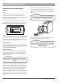
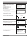
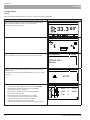
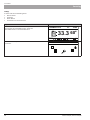
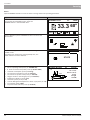
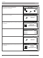
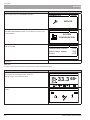
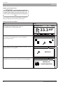
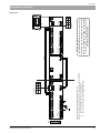
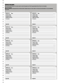
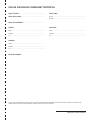
To Installers
Electrical Connections
Burner Connection
Outdoor temperature sensor, CTZ-01
Connect the boiler’s power supply cable to the socket in
the burner.
Temperature
(°C)
Resistance
Min. (kΩ)
Resistance
Nom. (kΩ)
Resistance
Max. (kΩ)
External Temp Sensor Connection
-40
329.927
345.275
361.300
Install the external temperature sensor on the external
wall from the north, or north-west side in such a way that
the morning sun does not affect the temperature read
outs. The sensor is connected to the CAN communication
module with two-wire conductor. Minimum area of the
conductor is 0.4 mm2, and length max 50 m.
-30
173.153
180.031
187.164
-20
95.009
98.187
101.460
-10
54.247
55.745
57.278
0
32.101
32.813
33.537
10
19.621
19.956
20.296
Heating Medium Temp Sensor
20
12.351
12.504
12.657
The boiler is supplied with temperature sensor. Connect it
to the Cam communication module and install on the central heating circuit, directly behind the mixing valve. The
sensor must tightly fit to the circut and be well insulated.
25
9.900
10.000
10.100
30
7.952
8.050
8.148
40
5.227
5.314
5.401
50
3.517
3.589
3.662
60
2.418
2.476
2.536
70
1.695
1.743
1.791
80
1.211
1.249
1.288
90
0.881
0.911
0.943
100
0.651
0.675
0.701
110
0.488
0.508
0.529
120
0.372
0.388
0.405
External Control
Burner
Operation of the burner can be stopped by an external
signal (heat pump, external control system, etc.) from a
non-potential relay connected to the CAN communication
module, input No. IN8. For the wiring diagram, see page
18.
External circulating pump output
External circulating pump (e.g. hot utlity water pump) is
connected to the CAN communication module. Operation
of the pump depends upon output values from the boiler
controller. For the wiring diagram, see page 18.
Internal boiler temperature sensor, CT2a
Temperature
(°C)
Resistance
Min. (kΩ)
Resistance
Nom. (kΩ)
Resistance
Max. (kΩ)
3-way valve with actuator output
-40
329.927
345.275
361.300
Connect the 3-way valve for the heating medium temperature control to the CAN communication module. This
valve operates basing on the values entered on the control
panel. For the wiring diagram, see page 18.
-30
173.153
180.031
187.164
-20
95.009
98.187
101.460
-10
54.247
55.745
57.278
Tables of the Sensor Resistances
0
32.101
32.813
33.537
10
19.621
19.956
20.296
20
12.351
12.504
12.657
25
9.900
10.000
10.100
30
7.952
8.050
8.148
40
5.227
5.314
5.401
50
3.517
3.589
3.662
60
2.418
2.476
2.536
70
1.695
1.743
1.791
80
1.211
1.249
1.288
90
0.881
0.911
0.943
100
0.651
0.675
0.701
110
0.488
0.508
0.529
120
0.372
0.388
0.405
130
0.306
0.321
0.346
140
0.237
0.259
0.271
150
0.153
0.177
0.194
Internal temperature sensor, CTP-02 (room)
Temperature (°C)
Resistance (kΩ)
0
32.56
10
19.87
20
12.49
30
8.06
40
5.33
50
3.6
60
2.49
70
1.75
80
1.26
90
0.91
100
0.68
PELLUX 100/20, PELLUX 100/30
19