1
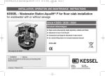
WRC Approval. Nr. UC7982
DIBt Approval Nr. Z-42.3-374
Operators Manual
Revision 2 from 04.12.2009
Sales and Distribution:
Kanaltechnik GmbH
List of Contents
1. System description
1.1 Definition
2.2 System description and Installation Procedures
1.3 Materials
1.3.1 Stainless steel
1.3.2 EPDM-rubber
1.4 Range of applications
1.4.1 Trouble shooting and failure modes
2. Using Quick-Lock
2.1 Inspection and preparation of the damaged Pipe section
2.1.1 Inspection
2.1.2 Preparation of the damaged Pipe section
2.2 Equipment, material and preparation for the Quick-Lock Installation
2.2.1 Equipment
2.2.2 Material
2.2.3 New! Quick-Lock sleeves with End crimping
2.2.4 Preparation of the Quick-Lock sleeve
2.3 Quick-Lock Installation
2.3.1 Positioning of the Quick-Lock sleeve
2.3.2 Procedure for single Installations
2.3.3 Procedure for Serial Installation
2.3.3 Serial installation with non crimped sleeves- version 1
2.3.3 Serial installation with crimped sleeves- version 2
2.3.4 Installation using laser positioning
2.3.5 Quick-Lock sleeve for joint displacement
2.3.6 Ground water infiltration
2.3.7 Root Infiltration
2.3.8 Concrete pipes with exposed reinforcement
2.3.9 Rehabilitation of plastic pipes
2.3.10 Quick-Lock in sealed pipe systems
2.3.11 Removal of Installed Quick-Lock sleeves
2.3.12 Air Cushion Release by means of Fast venting
Technical data sheet for Quick-Lock
Table of Installation pressures (compression pressures)
Product recommendations
3
3
3
4
4
4
4
4
5
5
5
5
6
6
6
6
7
8
8
9
11
12
13
14
15
16
17
17
18
18
19
19
Annex 1
Annex 2
Annex 3
1
Stand: 04.12.2009
Foreword
Dear Quick Lock user,
We have produced this Manual with the intention of providing you with all the
necessary information and operating instructions for installation of the Quick Lock
Local Patch repair system.
It contains pictures, diagrams and information that is based on extensive testing and
field experience, collected over the 10 years of daily use by our long term installation
partners.
Quick Lock is one of the most user-friendly Local Patch repair systems.
Still, the installer is required to have fundamental knowledge in sewer construction and
background experience gained in sewer renovation.
This user manual cannot replace the individual “hands on experience” gained by the
installer, but it does provide helpful tips and hints that will facilitate your work with the
Quick Lock system.
Uhrig as manufacturer provides schooling and practical training for their installation
partners.
We would appreciate any feedback concerning your experience made with the Quick
Lock system during installation. Together we can so develop and advance the Quick
Lock technology.
Should you have any queries or require further information, please contact us.
Geisingen, December 2009.
Uhrig Kanaltechnik GmbH
Am Roten Kreuz 2
D-78187 Geisingen
Germany
Mark Biesalski
Division Manager
Telefon +49 (0) 7704 / 806-33
Fax +49 (0) 7704 / 806-50
e-mail [email protected]
2
Stand: 04.12.2009
1. System description Quick-Lock
1.1 Definition
Quick-Lock is a local patch Sleeve made of made of V4A
stainless steel and an EPDM compression seal.
The system uses a purely mechanical locking system.
It is very variable, adapting to all pipe sizes from
DN 150 to DN 700 and can be extended almost limitlessly
in length.
fig. 1.1-(1): Quick-Lock.
The Quick-Lock system can be used for all normal
Sewer networks, fountain and drinking water pipe systems.
1.2 System description and Installation procedure
Quick-Lock consists of a rolled V4A Stainless steel sleeve
covered with an EPDM rubber seal.
The repair and seal of the damaged areas in the pipe network
is achieved by means of permanent pressure contact of the
EPDM rubber seal to the pipe, wall held in place through the
expanded stainless steel sleeve.
fig. 1.2-(1): compression principle
The stainless steel sleeve compressed / rolled is approx.
40 mm smaller than the nominal diameter of the pipe
to be rehabilitated.
Two parallel toothed “rails” have been stance into the sleeve. In
each toothed rail is a lock and gear mechanism, which
guides the sleeve plate when expanding.
Upon reaching the end position and pressure contact at the
pipe wall has been achieved, the gear mechanism locks the
sleeve permanently in place.
During the expanding procedure the „click“ sound of the gear
fig 1.2 (2): rolled-up stainless steel sleeve with
wheels in the locking Mechanism is apparent.
toothed strips and locking mechanism
The distance between tooth notch and tooth head is one click.
This means that the max. possible reduction after expansion is the return of a tooth head to
the next lower groove a which is approx. 0,65 mm in diameter depending on the nominal width
of pipe.
The geared locking mechanism moves in a constant fluid motion.
Distance from gear wheel top to
gear wheel top: 4 mm
Direction of
rotation During
expansion
process
Tooth Strip
direction
of rotation
during expansion
Gear wheel
Crown
Gear wheel
groove
Tooth Strip
Stand: 04.12.2009
Return stop
(locking function by means
of the middle gear wheel)
3
1.3 Materials
1.3.1 Stainless steel
The Quick-Lock sleeve is made of V4A stainless steel, grade 1.4404.
Stainless steel in this quality is characterised by its high resistance to corrosion.
Quick-Lock is designed for the use in municipal sewage networks.
Before using Quick lock in industrial sewage networks the affluent in the network should be
analysed and the corrosion resistance of the stainless steel checked.
1.3.2 EPDM-rubber
The thermoplastic EPDM rubber seal has also been designed for use in municipal sewage.
EPDM has excellent physical characteristics and resistance to deterioration, ozone,
atmospheric and environmental influences, alkali and different base chemicals.
Under certain circumstances the EPDM rubber can react with some substances:
• solvents
• ether, ester, keton, methyl chloride
• animal and vegetable fats, oils, fuels
• concentrated fruit juices, oxidizing acids
Note: Before using Quick-Lock in industrial, non municipal sewage networks, the
concentration and resistance of the V4A stainless steel and EPDM rubber must be
checked!
1.4 Range of applications
1.4.1 Forms of Common damage in Sewer pipe networks
• Cracking
(longitudinal, radial and traverse cracks)
• Shard formation
• Infiltration and leaking Joints
• Settling sagging / Joint displacement
• Closing / sealing dormant unused laterals
• Corrosion / flaking / wear
(Reinforced concrete pipes with exposed steel)
• Ground water Infiltration
(Silt build up)
• Weakened pipe static
(Cracks and shard formation, pipe deformation)
• Root infiltration
(Reduction of pipe diameter)
4
Stand: 04.12.2009
2. Quick-Lock Installation
2.1 Inspection and preparation of the damaged section.
2.1.1 Inspection
• Before installation of the Quick-Lock Local Patch system, the damaged Pipe section
should be inspected and the accessibility for the Quick-Lock installation Trolley checked.
• At least one possible access through a manhole or revision opening is required for
installation.
• The sewer manhole should have at least a nominal width of DN 800, to allow the
camera and installations system to be fed into the pipe. The sewer channel must also
have sufficient room to move the installations trolley with sleeve into position.
2.1.2 Preparation of the damaged section
• All Pipe Sections must be cleaned through high pressure jetting before every
Quick-Lock installation.
• Hardened deposits, root infiltration, protruding pipe connections must all be mechanically
removed by means of appropriate milling tools.
There should be no obstacles hindering access to the damaged pipe section.
Example for the space required, allowing installations trolley + sleeve into the damaged section:
Pipe Centre
Trolley centre
Note: The original installation trolleys run with their centres approx. 0,5 cm under the pipe
centre.
Example of Required Space calculation:
Ø Pipe :
Ø Q.L. rolled, incl. EPDM rubber :
300 mm
263 mm (see technical data sheet)
300 mm – 263 mm = 37mm top and bottom in total
Top:
37 mm / 2 = 18.5 mm + 5 mm (Centre is offset pipe / packer) = 23.5 mm
Bottom: 37 mm / 2 = 18.5 mm – 5 mm (Centre is offset pipe / packer) = 13.5 mm
• There should be no solid matter such as sand or gravel in the damaged sections.
• Joint displacements of more than 1,5 cm need to be milled before installing single sleeves
or two Quick-Lock sleeves in serial. [see chapter 2.3.4].
• Normally Quick Lock can be installed in live or running sewer operations.
The back build up height should not amount more than approx. 20 % of the sewer cross
section. If too many solid parts are washed in during sewer operations, the damaged section
will need to be closed off with bungs or packers.
In this case over pumping or tankering is advisable.
5
Stand: 04.12.2009
2.2 Equipment, material and preparations for the Quick-Lock installation.
2.2.1 Equipment
The following Equipment is required for the economic Quick-Lock installation:
• Standard sewer camera (CCTV), matching the pipe diameter
of the damaged section.
Ideally the camera should have pivoting and zoom functions.
• Quick-Lock installation trolley acc. to pipe dia
• Quick-Lock connecting rod for connecting camera and trolley
• Quick release valve [see 2.3.12]
• Standard compressed air system onboard vehicle or
Compressor with an output of at least 5,0 bar.
• At least 100 m. of compressed air hose on a reel.
• A suitable milling robot for job preparation.
2.2.2 Material
Depending on the form of pipe damage, the following materials are
necessary for preparation of the Quick-Lock sleeve installation;
fig.. 2.2.1 (1): equipment
• Sharp knife
• Talcum powder
• Superglue
• Biodegradable contact spray or food lubricant
• Swelling rubber
(ground water infiltration)
• Mineral Flex-adhesive
(root infiltration, corrosion reinforced concrete pipes)
2.2.3 New! Quick-Lock sleeves with Crimped End
One end of the sleeve has been mechanically widened to form a “lip” closing the distance
between the wall of the existing pipe network and the Quick Lock Sleeve.
The reason for this new development is to ensure a smoother water flow and a higher
mechanical resistance to jetting nozzles during high pressure cleaning of the pipe network.
This also ensures a tighter seal at the sleeve end to the wall of the existing pipe.
The crimping size is between 3 to 5 mm in respect to the standard width and dimensions of
the non compressible EDPM rubber Sealing Gasket used.
The crimped end closes the gap between the Quick Lock Sleeve and the existing Pipe wall,
but does not exert any pressure on the walls of the damaged existing pipe.
fig. 2.2.3 (1): sleeve without crimping
fig. 2.2.3 (2) sleeve with crimping
This technical modification affects the old installation procedure.
6
Stand: 04.12.2009
The correct procedure is described in the following pages.
2.2.4 Preparation of the Quick-Lock sleeve
a) Transportation Strip
The white adhesive strip with the Quick Lock Logo attached to the
sleeve joint overlap, prevents any movement during transport.
Before installation, cut half of the adhesive strip in the area of
the sleeve overlap.
If the adhesive strip is cut completely through, the risk is that the
sleeve can start to expand prematurely during transport into position
in the damaged pipe. If the sleeve expands prematurely then this
will hinder movement through the pipe section.
If the adhesive strip is not cut halfway through, the risk is that the
Sleeve expands too abruptly after snapping the adhesive strip
fig. 2.2.4 (1): cut adhesive strip only halfway through
during the expansion procedure, and the geared locking
mechanism can be damaged or destroyed.
b) Fitting the EPDM rubber
• For better handling sprinkled inside the EPDM rubber with talcum
powder. This enables the EPDM rubber to be slipped more easily
over the stainless steel sleeve and friction between rubber and
sleeve are reduced during the expansions process.
• With the Sleeve on its end, Slip the EPDM rubber over the sleeve
so that the rubber overlap for serial installation is at the top.
New! For fitting the EDPM rubber on the crimped sleeve, make
sure that the crimped end of the sleeve is at the bottom (Sleeve
standing upright the crimped end on the ground)
And the rubber pushed over the uncrimped end. As normal
Photo. 2.2.4 (2): Sprinkle Talc inside
the rubber overlap for serial installation is at the top.
The opposite rubber edge should sit behind the start of the
crimping.
EPDM rubber
• The rubber overlap is cut off for single Quick Lock installations.
Check first that the distance between the sealing profiles is sufficient to cover the length of the
damaged section. If the distance is not sufficient then a serial installation is required to seal
the damaged pipe section. In this case the rubber overlap should not be cut off.
• For single installations the EPDM rubber is to be cut and set on the sleeve so that
the rubber edge is approx. 3 mm behind the edge of the stainless steel sleeve. [photo.2.2.4 (5)]
c) Fixing EPDM rubber
approx 3 mm
Photo 2.2.4 (3):slip EPDM rubber over
Stand: 04.12.2009
Photo 2.2.3 (5): distance of EPDM rubber
from sleeve edge
Photo2.2.4 (4): EPDM rubber. Cut overlap
7
• To avoid movement of the EPDM rubber seal on the stainless steel sleeve during the
transport to the damaged pipe section, fix the rubber to the stainless steel sleeve above the
lock positions on both sides and opposite ends with a dot of superglue.
• The superglue should in no way be allowed into the plate overlap, otherwise due to
the superglue adhesion, the expansion of the sleeve is no longer possible.
• If the EPDM rubber is not fixed, there is the possibility that it can slide off during transport
and before reaching the damaged pipe section.
fig.2.2.4 (6): fix EPDM rubber
fig.2.2.4 (7): fix EPDM rubber
d) Spray toothed rail and locks with a lubricant spray
• During the Quick-Lock expansions process friction can
occur in the Sleeve overlap. To enable a smooth and
constant running of the toothed rails and gear wheels
spray the area lightly with a biodegradable lubricant
spray.
To avoid any complications during installation, take care
that the lubricant spray does not come into contact with
the inside or outside of the EPDM rubber seal.
fig. 2.2.4 (8): spraying of the toothed rail
2.3 Quick-Lock installation
2.3.1 Positioning of the Quick-Lock sleeve on the installations trolley
Middle of toothedtrail at
12. o’clock position
• The Quick-Lock sleeve is positioned on the installations
trolley so that the middle of the tooth rail is seated at the
12.00 o’clock position. The lock, depending then on line
of sight, is seated then in the 11.00 or 01.00 position.
During the installation process the lock “wanders” and
sits after completing the installation process in the
12.00 o’clock position [fig.2.3.1 (1)].
fig. 2.3.1 (1): position of the locks
Stand: 04.12.2009
8
• Due to the reduced space with serial installations and also
depending on the type of camera and attachment method of
the connection rod, it may be necessary to position the sleeve
on the installations trolley with the lock in the 12.00 o’clock
position.
This is to avoid any snagging of the installations trolley
when passing through a pipe section where a Quick Lock
has already been installed.
This can also apply if during serial installation the view of
the expanding lock is hindered by a sleeve lock that has
already been installed. After the installation the locks should
then sit, depending on the direction of viewing, in the
11.00 or 01.00 o’clock position.
end of
toothedtrail
fig.. 2.3.1 (2): wheel sets
• During preparation for installation one should be
accustomed to setting the sleeve on the installations trolley
with tooth rails always facing in the same direction.
This ensures a regular lock alignment with serial installation.
• Select the correct wheel set for the Pipe diameter where
the Quick Lock is to be installed. Position the Q.L. sleeve as
far to the front of the trolley so that one has good visibility of
the edge of the sleeve through the CCTV camera.
• The positioning of the sleeve on the trolley should
normally be carried out in the sewer pipe.
fig.. 2.3.1 (3): Pos. on the Installation trolley
2.3.2 Installation procedure for single Sleeves
It is more economical to use the camera robot to position the
installations trolley.
The process can also be carried out with rods or other means,
but the camera is required to observe the correct positioning
of the trolley and installation in the damaged area.
• If there is lack of space but 2 manholes are available, it can be
advisable to feed the camera in from one manhole drive
through
and collect the sleeve in the second manhole.
fig. 2.3.2 (1): connection camera-Installations trolley
• Connect the camera to the installations trolley with the coupling rod, connect the compressed
air supply and lightly inflate the cushion of the installations trolley to secure the sleeve on the
trolley with a pressure of approx. 0,5 bar. The sleeve is now secured from slipping off the
trolley. The attachment pressure of approx. 0,5 bar can vary depending on the compressed air
system, nominal width and the installations trolley used.
9
Stand: 04.12.2009
We recommend that you first test and determine the correct pressure for your own system.
fig. 2.3.2(2): inflate cushion lightly and secure sleeve in position
• Position the Trolley with the Quick-Lock sleeve in the centre of the damaged area.
New! When installing crimped sleeves the crimped side must always be set
against direction of flow [fig. 2.3.2 (2)].
• The correct position can be either calculated from previous calibration of the damaged area
or live viewing through the CCTV camera. The distance from camera head to sleeve centre
must also be taken into account.
• Attach the Quick-Lock sleeve with a pressure of approx. 1,5 bar to 2,0 bar to the damaged
pipe wall. Make sure that the sleeve is at first only „lightly“expanded against the pipe wall. This
allows a possible position correction should this be necessary. Deflate the cushion slightly and
release the trolley, so that it can move forward and recentre again in the middle of the QL
sleeve.
• If the sleeve position is correct, the installation pressure of 2,5-3,5 bar is then applied.[See
Diagram. 2] (Depending on damage and type of pipe) Repeat the procedure once again. Make
sure that the trolley cushion is positioned in the centre of the sleeve and then apply the
installation pressure. The necessary installation pressure and compression of the EPDM
seal rubber has then been carried out.
Note: Where the pipe damage is in the form of longitudinal cracks or shard formations,
mainly in vitrified clay pipes, do not over expand the sleeve after the locking and
sealing of the damaged area has been achieved, otherwise the existing pipe could be
further damaged. Torsion forces can damage the lock or the tooth rails if the sleeve is
eccentrically expanded (out of centre)
fig. 2.3.2 (3) positioning and installation pressure
Stand: 04.12.2009
10
• Check the correct position of the sleeve with the camera. For this purpose, pivot the camera
lens along the edges of the sleeve. This should show that the sleeve is now pressed equally
against the pipe wall. [Photo.2.3.2 (4)].
• During installation or repositioning it can occur that one end of the sleeve needs to be
retightened.
• In glazed vitrified clay pipes the camera spotlights can cause a reflection of the sleeve edge
on the pipe wall. [Photo. 2.3.2 (5)]. The client could misinterpret this as a gap and believe that
the sleeve is not sitting correctly. This optical illusion disappears after pivoting and changing
the camera angle.
Reflections
on
pipe wall
Dia. 2.3.2 (4): Installed sleeve compressed
against the pipe wall
dia. 2.3.2 (5): reflections
2.3.3 Procedure for serial installation
The serial installation should be used when the damaged section is longer than the distance
between the two sets of double rings on the EDPM rubber. Cut the rubber overlap only from
the last sleeve to be installed. The installation process and the installation pressures are the
same for single and serial installation.
Distance between sealing rings
• Slide the EPDM rubber over the stainless steel sleeve so that
the distance between the sealing rings and sleeve edge is the
same or larger than the distance between lock and sleeve
edge. Only then can a seal within the rubber overlap be certain.
• Always make certain that the seal rings under the rubber
overlap are not sitting too close to the sleeve edge.
and sleeve edge
Distance between the
lock and sleeve egde
• The EPDM rubber can also be shortened by approx. 1,5 cm
This means that the rubber strip between sealing rings and
sleeve edge is cut, in order to reduce the thickness of the offset
in the sleeve overlap.
fig. 2.3.3. (1): distances
• The first sleeve is installed with at least one set of ring seals in an intact
pipe area
• Ideally the installation should always be carried out against the direction of flow.
The small offset in the area of overlap should cause no obstruction for the pipe flow.
New! Quick Lock with crimped and non crimped ends can be used together for serial
installation. The leading sleeve against direction of flow should always be a crimped
sleeve.
We strongly recommend that the installation be carried out according to the
Diagram as in version 1 shown.
11
Stand: 04.12.2009
Version 1: Installing non crimped sleeves against direction of flow
fig. 2.3.3 (2): Install QL sleeve without crimping first the second sleeve slots inside, metal overlapping
• The area between lock and sleeve edge of the first sleeve can be fully used for setting the
following sleeves. In no case set the following sleeve on the lock of the first sleeve.
When possible use the laser for guiding as described in the following chapter.
fig. 2.3.3 (3): photo Sleeve overlaps Sleeve in Sleeve
fig. 2.3.3.(4): photo A finished serial installation. All locks in row
dia. 2.3.3 (5): serial installation in sleeve without crimping last sleeve installed with crimping
12
Stand: 04.12.2009
• The rubber overlap of the last sleeve to be set is cut; the crimping is aligned against the
direction of flow.
Version 2: Installation of crimped sleeves in direction of flow
Disadvantages:
The Pipe cross section is reduced in size
The overlapping against the direction of flow forms a “stepping” which
disturbs the flow and natural hydraulics
Installed sleeves and smaller cross sections are less accessible for machines
fig 2.3.3 (7): Sleeve in Sleeve serial Installation with Sleeve crimping.
In diagram 2.3.3(7), the Pipe cross Section is reduced by approx. 2 to 4 mm, compared to
diagram 2.3.3(5), and is caused by the crimped ends installed inside another sleeve.
In small pipe dimensions and where existing pipes are deformed, the installed sleeves not
only reduce the pipe diameter but make it also more difficult to access or drive through with
the installation trolley and additional sleeves.
If it is necessary to install further sleeves in the same pipe network, it is advisable to carry out
the installation from an alternative second manhole or access point.
Drive the installations trolley, with sleeve, through the rubber overlap of the last sleeve that
was installed, by a full sleeve length.
In doing so the rubber overlap of the already installed Sleeve folds inwards over the Trolley
that is passing through.
Now the sleeve is positioned in flow direction, whereby the rubber overlap of the last Sleeve
springs forward folding out again to the normal position, the installations trolley can then be
moved into the correct position and the sleeve installed.
13
Stand: 04.12.2009
2.3.4 Working with the laser positioning marker
The Quick Lock Sleeves can be installed much faster and accurately using the laser positions
marker, which is installed on the end of installations trolley.
Here we explain two methods for serial installation „sleeve in sleeve“:
Method 1
• The laser position marker is mounted on the front end of the
installations trolley, either next to the air connector [fig.
2.3.4 (1)] or seated directly above. The laser must not
protrude over the top of the end plate.
If there is there is no predrilled and threaded hole in the end
plate of the installations trolley for fitting the laser head, then
drill a hole into the front end plate and tap thread for max M4
and a max. depth of 13 mm.
• The Quick-Lock sleeve is positioned on the trolley so that the
laser beam and sleeve edge are both visible when in the pipe to
be rehabilitated.
• The installations trolley and sleeve are positioned
in the sewer so that the laser beam shines on the back
lock edge of the sleeve already installed. [fig. 2.3.4 (1)].Ca. 0,5 –
• After the installations process the sleeve edge should
Sit approx. 0,5 – 1,0 cm behind the lock of the already
installed sleeve [fig. 2.3.4 (2)].
Note:
With this method the installations trolley is not
sitting in the middle of the sleeve during expansion.
Before installation, grease the overlapping area of the
stainless steel faces of the Quick Lock sleeve to avoid
the sleeve expanding eccentrically.
fig. 2.3.4(1): Positioning of the Sleeve with laser aid
fig. 2.3.4 (2): Distance of sleeve end to lock
Method 2
For the second method the installation is carried out using distance measurement.
• Position the sleeve in the centre of the installations trolley. Measure the distance
between sleeve end and laser. Use the same distance measurement when positioning the
other sleeves to be installed. (Tip:) Mark the position on the trolley top and inside of all the
Sleeves with a marker to so that the laser beam can be matched into position in the pipe
system and the following sleeve edges always sit in the same position.
Always make sure that the sleeves are facing in the same/ right direction.
The installation can then begin.
Transfer difference
Difference
Installations trolley
!!Always follow the safety instructions for „target lasers“!!
14
Stand: 04.12.2009
2.3.5 Installing Quick-Lock at displaced joints
Displaced or offset joints with openings up to 1, 5 cm can be rehabilitated with a single
Quick-Lock sleeve.
If the joint offset exceeds 1,5 cm then they should be milled. The offset can also be overcome
by installing 2 Quick-Lock sleeves in serial installation.
The installations process with two sleeves is the same process as used in serial Installations.
[Diagram 2.3.5.], The only difference is in installing the first Sleeve.
fig. 2.3.5 (1): joint seating repair
• The first Quick-Lock sleeve is placed approx. 30 cm in the offset joint. The rubber overlap is
not cut off.
• The second Quick-Lock sleeve is installed with approx. 1,5 cm, of the Quick Lock
Sleeve [Diagram 2.3.5.] inserted into the first sleeve. The double sealing rings grip inside
the rubber overlap of the first sleeve installed creating a seal. So jointing, the two sleeves
form a flexible area that compensates for any slight movement or uneven levels in the pipe
joint.
fig. 2.3.5 (2): detail Joint seating with Quick Lock
15
Stand: 04.12.2009
2.3.6 Ground water infiltration
When installing Quick Lock in pipes where the pipe inner surface structure is extremely rough,
strongly corroded surfaces, or there is evidence of a strong ground water infiltration, we
recommend that the blue swelling rubber strip is used to insure that a seal is always achieved.
This is attached over the EDPM rubber seal. We have found from experience that the use of
the swelling rubber is indispensable when working with such worn and damaged pipes.
• The blue rubber strip is fitted as described in following diagrams.
The swelling rubber strip is fitted between the double sealing rings of the EDPM rubber.
• Cut the required length from the roll. The length should fit snugly around the sleeve and
EDPM rubber after jointing.
• Joint the ends of the swell rubber with a dot of superglue.
• Slip the swell rubber over the double sealing ring of the EDPM rubber.
Make sure that swell rubber ring fits tightly around the EDPM rubber.
fig. 2.3.6 (1): Cut the Swelling Rubber to the correct length
fig. 2.3.6 (2): join the ends of the swelling rubber with super glue
i
g
.
2
.
3
.
6
fig. 2.3.6 (3): Finished Sleeve with Swell rubber fitted
(
1
)
:
s
h
o
r
t
e
n
t
h
e
Stand: 04.12.2009
e
x
p
a
n
s
i
v
e
r
u
16
2.3.7 Root infiltration
Follow the special procedure to stop the root growth finding a way through and along the
length of the quick lock seal and to avoid reclamation or repeat installations when installing
Quick Lock in pipe networks with root infiltration.
We find that even after extensive long term trials, that continued root growth cannot be totally
excluded.
• All root infiltration must be mechanically removed before rehabilitation can begin.
• The area between the double sealing rings of the EPDM rubber seal is coated with high
alkaline, mineral Flex adhesive
The coating thickness should be to the top of the sealing rings [photo: 2.3.7 (1)].
• To avoid loss of coating in the pipe during movement to the damaged pipe section, it is
important to use a product with adhesive qualities. The Flexible qualities ensure that the
coating does not tear and can expand with the EDPM rubber during installation.
[photo. 2.3.7 (2) and photo.2.3.7 (3)].
fig. 2.3.7 (1): Sleeve with coating
fig. 2.3.7 (2): The coatings flexible qualities
fig. 2.3.7 (3): The coating stretched
2.3.8 Surface erosion of Reinforced concrete pipes.
The procedure described under [2.3.7 root infiltration] can also be used for concrete pipes with
exposed reinforcing steel. The coating with high alkaline content forms a protective
environment around the exposed steel reinforcing. The alkaline content found in concrete is
the normal corrosion protection for the steel reinforcing.
• Exposed or protruding steel reinforcing must be removed before rehabilitation.
fig. 2.3.8 (1): Exposed protruding steel reinforcing
fig 2.3.8 (2): after rehabilitation
17
Stand: 04.12.2009
2.3.9 Rehabilitation of plastic pipes
The same Quick-Lock installations procedure can be used to rehabilitate Plastic pipes in
single or serial installation.
The following points should be taken into account before installation:
• The stated diameter of a plastic pipe often refers to outer diameter.
The stated size e.g. DN 250 does not mean that it has an inside diameter of 250 mm.
•It is common to find that plastic pipes with deformations, can limit the access for robots and
trolleys through the pipe network.
If the Quick-Lock sleeve can still be installed at the damaged section with the trolley in spite of
the deformations, then the sleeve adapts automatically to the deformation and increases the
pipe strength statically stabilising the area again.
•If you are unsure that a certain pipe size can be rehabilitated with Quick-Lock,
please feel free to contact us.
Our technical department can cross check if a quick Lock Sleeve can be supplied for the pipe
section concerned.
An adapted set of wheels for the installations trolley can be supplied for the project and can be
returned to us upon completion of the installation.
• Round drainage pipes can also be rehabilitated with Quick Lock without the function being
impaired.
Quick lock can also be used to rehabilitate damaged vertical pipes.
We would be happy to advise you with any project queries that you have.
fig. 2.3.9 (1): drain pipe before repair
fig. 2.3.9 (2): drain pipe after repair
18
Stand: 04.12.2009
2.3.10 Quick Lock in Sealed Pipe systems
The Quick Lock sleeve sealing takes place by compression of the EPDM rubber.
This method has achieved excellent sealing results.
If Quick Lock is used in sealed pipe systems, it is possible that pressure can build up in the
space between the EDPM double sealing rings and the old pipe.
This occurs especially in pipe systems with smooth walls (pipe/hose) and a dense structure
(e.g. plastic hoses, GRP pipes and glazed stoneware pipes)
This enclosed cushion of air (Hoover effect) may influence the purge stability and safety.
Figure 2.3.10 (1):Experimental Over pressure Setup
If the high-pressure jet or nozzle has contact with the sleeve edge, it is possible that the Quick
Lock sleeve may move, or the high-pressure water jet could penetrate the area between
sleeve and old pipe, increasing the already existing pressure pocket.
Trials have shown that the existing pressure pocket will, through diffusion, slowly dissipate.
2.3.11 Removal of Installed Quick-Lock sleeves
Quick-Lock is often used to seal dormant or unused laterals.
Many clients require only a temporary sealing. This means
that Quick Lock sleeves used as a temporary seal, then
need to be removed.
The same applies in the case of a misplaced or dislocated
Sleeve. The locking mechanism must be removed for this
purpose.
• To remove an installed Quick-Lock sleeve, a milling robot
with a metal cutting disk is required.
Depending on the type of milling robot used by your
Company the mounting pin for the cutting disk may need to
be specially made.
Photo. 2.3.11 (1): milling robot with Steel cutting disk
19
Stand: 04.12.2009
• Two cuts are required to dismantle each locking mechanism.
The locking gear wheel is destroyed with the first cut, set
just behind the two centre rivets.
2nd cut
With the second cut the centre rivets holding the gear
wheels in place and in the toothed rails are removed
[photo. 2.3.11 (2)].
1st cut
Rivets
The cover plate should now fall away, the sleeve tension
should release and unlock.
• The Quick-Lock sleeve should contract due to the tension
release and the EPDM rubber shrinking back.
The stainless steel sleeve can then be picked up with the
milling robot head in the centre of the sleeve and removed
from the damaged pipe section.
Photo 2.3.11 (2): Locking Mechanism with Cover plate
2.3.12 Faster venting of the installations cushion with an air release valve
To vent the expansion cushion faster after installation, a quick release valve can be installed
on the camera robot, between the pressure hose and the rod connecting the installations
trolley.
This bypasses the long hose leading to the manual release valve above ground.
Inlet Connection for compressed air
Connection for Installations trolley
Inlet Connection from Compressed-air System
Hose connecting to installations trolley
connection for
vent/ release
Photo. 2.3.12 (1): air Venting / release valve
Photo. 2.3.12 (2): example for valve installation
20
Stand: 04.12.2009
Technical Data Sheet
Quick-Lock
Sleeves
V4A Sleeve
Pipe DN
Sleeve Length
Wall
Thickness s
mm
Description:
mm
L
400
mm
s
1
mm
da
120
150
400
1
151
188
400
1,2
161,5
200
400
1,2
184
225
400
1,2
191
238
400
1,2
203
250
400
1,2
222
276
400
1,2
245
300
400
1,2
252
315
400
1,5
290
350
400
1,5
300
380
400
1,5
322
400
500
2
362
450
500
2
424
500
500
2
515 (*490)
600 (600 NL)
485
2
570
700
485
2
695**
800**
* Special dimension for shaft manhole (Netherlands)
State: 20.11.2008
Sealing Rubber
V4A Pipe, rolled, dia
max. Mounting Diameter DA
Rubber
Diameter
Rubber
Thickness
Sealing Knob
Height
Total Diameter, rolled
Total Weight.
mm
DA
149
mm
Dg internal
117
mm
S/G
2
mm
Hn
4,0
mm
Dg
132
kg
188
157
2
4,0
163
2,7
201
157
2
4,0
174,5
2,82
227
157
2
4,0
196
3,95
236
197
2
5
205
4,18
252
197
2
5
217
4,43
276
197
2
5
236
4,6
305
242
2
7
263
5,35
315
242
2
7
270
6,64
355
288
2
7
308
7,34
377
288
2
7
318
7,74
405
315
2
8
342
8,91
455
337
2
8
382
15,94
2,25
505
410
2
8
444
16,76
607 (*610)
511
2
9
537 (*512)
20,23
713
555
3
9
592
24,03
815
680
3
9
719
27,0
Annex 1
Pressure Table for Installation (Expansion Pressure)
Type of Pipe
Forms of Damage
Stoneware, asbestos
cement, PVC and
concrete pipes
Shard formation and
longitudinal cracks
Reinforced concrete,
GRP plastic (PE,PP),
and cast iron pipes
ND from to
DN 150
DN 200
DN 250-700
Circumference and radial DN 150
cracks, Infiltration and
DN 200
leaking joints
DN 250-700
Other forms of damage
DN 150
DN 200
DN 250-700
Packer 2. Generation
approx. 4.0 – 4,5 bar
approx. 3,0 – 3.5 bar
approx. 2,5 – 3.0 bar
approx. 4.0 – 4,5 bar
approx. 3.5 – 4,0 bar
approx. 3.0 – 3,5 bar
approx. 4.0 – 4,5 bar
approx. 3.0 – 3,5 bar
approx. 3.0 – 3,5 bar
The pressures shown in the table above are to be used for reference purpose only.
Factors that influence the readings shown to the operator during installation can vary, depending on the type of compressed
air system used, the age, quality and precision of the instruments registering the pressures.
When installing the Quick Lock Sleeve, the type of damage to the existing pipe and the equipment used need to be considered
when setting the actual installation pressure. These conditions can vary from one case to another.
For the1st generation installation Trolleys (see figure 1) increase the table values by a further 0,5 bar.
During installation, increase the application pressure slowly, especially in case of longitudinal cracks and shard formations.
When it is apparent that movement in the cog- strip locking system has stopped during the slow pressure build-up, then the
maximum required expansion pressure has been reached. Experience has shown that it is advisable to count the number of teeth
that remained between the lock and the end of the locking strip.
The warranty for the supplied packer bladder cushions covers only case of proven manufacturing faults.
External damage to the packer bladder cushion in the form of punctures is the main cause for reducing the installation trolleys
service life span.
Figure 1: 1st Generation Packer
Stand: 03.12.2009
Figure2: 2nd Generation Packer
Annex 2
Auxiliary Materials Recommended for Use with the Quick Lock System
Product Description
Manufacturer
Item No.
Application Purpose
saBesto 300 ml
Food lubricant
Würth GmbH & Co. KG
74650 Künzelsau (Germany)
Phone: +49 (0) 7940 / 15 – 0
www.wuerth.de
893 107 1
To oil the tooth strips and gears prior to the
expansion process.
Bio-degradable, used in food industry.
240460
To fix the EPDM rubber sleeve on the stainless steel
sleeve.
You can also use gel-type superglue in order to
prevent this from flowing between the overlap.
Ropid 100
Superglue, low viscosity
Conrad Electronic
Klaus-Conrad-Hirschstraße 1
92240 Hirschau (Germany)
Phone: +49 (0) 180 / 531 21 11
www.conrad.com
Talkum TipTop 500g
Sprinkler can
Automotive spare parts trade, bicycle trade
Hydrotite swelling rubber
Rectangular profile section
3.5/7 x 20
TPH
Techn. Produkte Handelsgesellschaft mbH
Gutenbergring 55 c
22848 Norderstedt (Germany)
Phone: +49 (0) 40 / 501166
PCI Carrament
Middle bed and preparation mortar
with flexible characteristics, grey
(Tile Adhesive)
State: 20.11.2008
PCI Augsburg GmbH
Piccardstraße 11
86159 Augsburg (Germany)
Phone: +49 (0) 821 / 5901-0
www.pci-augsburg.de
To sprinkle the EPDM rubber sleeve before putting
over the stainless steel sleeve. Frictional force
between stainless steel and rubber is reduced
considerably.
335112
An additional seal against ground-water infiltration in
addition to the EPDM rubber sleeve.
To coat the EPDM rubber sleeves when used for root
infiltration and exposed steel in reinforced concrete
pipes.
Annex 3