1
88
Communication
Serial Communication Options
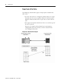
The native RS-485 and optional RS-232 communication ports provide
basic serial asynchronous communication capabilities.
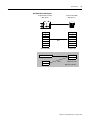
The RS-485 communication standard supports multi-drop
communication between a master station and up to 31 slaves on a
single network up to 1219 m (4000 ft) long. For satisfactory
communication performance, however, we recommend connecting no
more than 8…12 power monitors to an RS-485 multi-drop network.
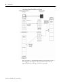
The optional RS-232 communication port has several configuration
settings that support the use of modems for point-to-point and
point-to-multipoint communication. You may select Hardware
Handshaking (CTS/RTS) and adjust the Delay parameter to match
your choice of modem hardware. Please refer to Configuring Optional
RS-232 Communication for detailed information on these settings.
The power monitor does not initiate messages nor does it support
modem dial-out capabilities.
Allen-Bradley DF1 Half-duplex Protocol
The Allen-Bradley DF1 half-duplex slave protocol is supported by a
number of Rockwell Automation and third party products.
Please refer to DF1 Protocol and Command Set Reference Manual,
publication 1770-6.5.16, for further information.
The network master device must be configured as a DF1 polling
master. All devices on the network must be set to the same baud rate.
The node addresses of the power monitor must be listed in a
permanent or temporary polling list of the master device, and the
error checking must be set to CRC. When communication is
established, the RS-485 or RS-232 RX and TX status LED indicators
flashes alternately at a rapid rate. If you are using Rockwell Software
RSLinx software as a polling master, the power monitor appears in
RSWho if it is defined in the polling list. For best communication
performance using RSLinx software, keep the number of concurrent
clients to a minimum (for example, turn off the auto-browse function
in RSWho).
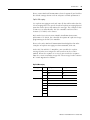
To communicate with an Allen-Bradley PLC-5, SLC 500 or
ControlLogix controllers, use message instructions that address the
DF1 master port number, the power monitor node address, the power
monitor data table address, (for example, F17:0 - Metering Power
Results), and the length of the file in elements. The target file must be
of the same data type as the power monitor data table, for example,
integer or floating-point.
Publication 1404-UM001E-EN-P - October 2006