1
Verifying the Operation of a DT340 Board
Testing Pulse Output
To verify that the board can perform a pulse output operation, do the following:
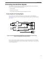
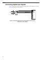
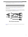
1. Connect a scope to counter/timer 0 on the DT340 board. Refer to page 44 for an example
of how to connect a scope (a pulse output) to counter/timer 0.
Note: The Quick DataAcq application works only with counter/timer 0.
2. In the Quick DataAcq application, choose Pulse Generator from the Control menu.
3. Select the appropriate DT340 board from the Board list box.
4. Select either Continuous to output a continuous pulse stream or One Shot to output one
pulse.
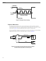
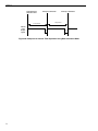
5. Select either Low-to-high to output a rising-edge pulse (the high portion of the total pulse
output period is the active portion of the signal) or High-to-low to output a falling-edge
pulse (the low portion of the total pulse output period is the active portion of the signal).
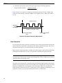
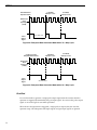
6. Enter a percentage or use the slider to select a percentage for the pulse width. The pulse
width determines the duty cycle of the pulse.
7. Click Start to generate the pulse(s).
The application displays the results both in text and graphical form.
8. Click Stop to stop a continuous pulse output operation. One-shot pulse output operations
stop automatically.
55