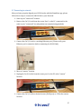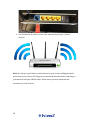
1
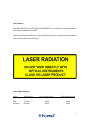
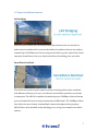
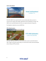
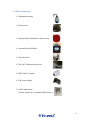
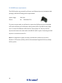
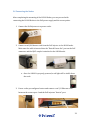
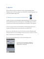
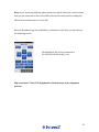
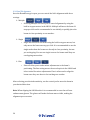
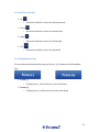
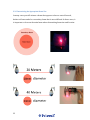
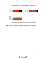
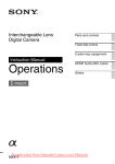
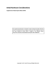
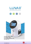
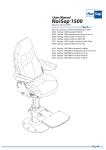
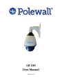
LH 100 User Manual Version 1.4.1 Table of Contents 1. SYSTEM OVERVIEW 6 1.1 SYSTEM INTRODUCTION 1.2 TYPICAL INSTALLATION SCENARIOS 1.3 NODE COMPONENTS 1.4 OPERATING PARAMETERS 6 7 9 10 2. INSTALLATION 11 2.1 SITE REVIEW 2.1.1 LINE OF SIGHT 2.1.2 SITE STABILITY 2.1.3 SITE ACCESSIBILITY 2.2 INSTALLATION COMPONENTS 2.2.1 REMOVE FOAM PADDING FROM THE OPTICS: 2.2.2 ROTATE DOME TO DESIRED POSITION 2.3 MOUNTING THE NODE: 2.3.1 NODE POSITIONING 2.3.2 MOUNTING STEPS: NOTE: FOR OUTDOOR INSTALLATIONS, THE INSTALLER SHOULD SEAL THE OUTSIDE OF THE HOUSING MOUNT WITH A SILICON SEALER TO ENSURE IT IS PROTECTED FROM WATER. 2.3.3 AVAILABLE MOUNTS AND BRACKETS: 2.4 LH100 POWER REQUIREMENTS: 2.6 CONNECTING THE NODES: 11 11 12 12 13 15 16 17 18 19 3. ALIGNMENT 24 3.1 BEAMBOSS COMMISSIONING APP FOR IPHONE/IPAD/IPOD 3.2 BEAMBOSS PC COMMISSIONING TOOL 3.2.1 SETTING PC IP FOR LINK COMMISSIONING: 3.3 USING BEAMBOSS COMMISSIONING APP 3.3.1 BEAMBOSS STATUSES: 3.3.2 PAN/TILT ALIGNMENT 3.3.3 PAN/TILT CONTROL PAD 3.3.4 CHANGING BEAM FOCUS 3.3.5 DETERMINING THE APPROPRIATE BEAM SIZE 3.3.6 TRACKING THE BEAM 3.3.7 RSSI INDICATOR 3.4 SWITCHING TO AUTO SEARCH: 3.5 LINK OPTIMIZATION: 3.6 SWITCHING TO IR LASER: 3.7 CONNECTING TO NETWORK: 24 26 26 28 29 30 31 31 32 34 34 36 36 36 37 4. MAINTENANCE: 39 4.1 RETURNING LINKS: 39 2 20 21 22 23 Laser Safety: Polewall’s LH100 is a CLASS 1M LASER PRODUCT in accordance to the international laser safety standard IEC 60825. Special care should be taken to avoid looking into the laser with optical instruments, such as binoculars and telescopes. Laser Specifications: Laser Wavelength Red 670 nm Infrared 850 nm Avg. output power Peak output power 1mW 1mW 3mW 3mW 3 Copyright info, Polewall AS All Rights Reserved The information contained herein is in connection to Polewall’s LH100 product. The installation manual is provided to Polewall customers and is meant for information purposes only. Polewall reserves the rights to change the information contained in the installation manual without notice. Polewall assumes no responsibility for any errors or inaccuracies that may appear in this installation manual. The Polewall and BeamBoss names and Logos are trademarks of Polewall AS. Contact Information: Polewall AS Email: [email protected] Vige Havnevei 78 Phone Support: +47 94 00 90 07 N-‐4633 Kristiansand Web: www.Polewall.com Norway 4 Limited Warranty Except as provided below, Polewall warrants the LH100 and its parts against defects in materials or workmanship for one year from the original ship date. During this period, Polewall will repair or replace defective parts with new or reconditioned parts at Polewall’s option, without charge to you. Polewall is not liable for any loss, cost, expense, inconvenience or damage that may result from use or inability to use the LH100. Under no circumstances shall Polewall be liable for any loss, cost, expense, inconvenience or damage exceeding the purchase price of the LH100. Warranty Conditions The above Limited Warranty is subject to the following conditions: 1. This warranty extends only to products distributed and/or sold by Polewall. 2. This warranty covers only normal use of the LH100 in accordance with limitations contained in product specifications and this installation manual. Polewall shall not be liable under this warranty if any damage or defect results from (i) misuse, abuse, neglect, improper shipping or installation; (ii) disasters such as fire, flood, lightning or improper electric current; or (iii) service or alteration by anyone other than an authorized Polewall representative; (iv) or damages incurred through irresponsible use. 3. You must retain your bill of sale or other proof of purchase to receive warranty service. 5 1. System Overview 1.1 System Introduction The LH100 is an easy to use, reliable, full duplex, wireless extension for your network. The LH100 can be installed and operated either indoors or outdoors, where a clear line of sight can be established between nodes and a link distance between 25 and 250 meters. The LH100 acts as a Fast Ethernet (IEEE 802.3/802.3u) transport device, and can be viewed as a wireless Ethernet extension cord. 1.2 Typical Installation Scenarios LAN bridging With Polewall’s LH100 you can now get fiber speed without the cost. Mount our nodes on your outside wall, or even on the inside of a window, and you are ready to transmit up to 100 Mbps over-‐the-‐air using our invisible, eye safe, optical link. Avoid expensive leased lines or the cost, hassle, and delay of trenching your own cable. Surveillance backhaul The LH100 uses point-‐to-‐point, optical wireless technology that can be combined with Ethernet cameras to set up a cost effective surveillance system for your home or enterprise. The LH100 is capable of transferring up to 100Mbps of data, allowing you to transmit all of your security cameras data in HD format. The 100Mbps of data also allows the user to daisy chain multiple cameras throughout their property. LH100 links can be installed easily allowing you to set up your connection in under an hour. 7 Small cell backhaul Polewall’s LH100 is an optical wireless access solution that allows carriers to increase their capacity and quickly expand their small cell backhaul coverage. The LH100 can be quickly deployed, and does not require the hassle of frequency licensing that commonly occurs with RF links. FTTx Rim Extension Polewall’s LH100 provides a low cost, non-‐intrusive, point-‐to-‐point alternative to fiber. Using our wireless optical nodes you connect more homes, faster and cheaper when rolling out FTTx networks. 8 1.3 Node Components Aluminum housing Dome Cover Red glass filter (Attached to dome cover) Patented Optical Module Pan/tilt device Flat Cat 5e Ethernet patch cord RJ45 Cat5e/6 coupler PoE power supply LH100 wall mount (Comes connected to standard LH100 nodes) 9 1.4 Operating Parameters The LH100 is designed for operation between ranges of 25 to 250 meters. Polewall is unable to guarantee link success if operated outside of our designed parameters. Bit rate 1 to 100 mbps Min link length 25 meters Max link length 250 meters Protocol IEE 802.3/802.3u Fast Ethernet Beam divergence 10 Autofocused Collimated Beam 2. Installation 2.1 Site Review Before installing the LH100 link, a complete site survey should be performed. It is important that installation sites have clear line of sight between nodes and the path is also measured for distance. The distance between sites can be found manually, or using an electronic range finding device, standard GPS product, or third party mapping software. Please ensure the distance between sites remains within Polewall’s specified range. Polewall cannot guarantee the operability of any links installed outside our designated range. The LH100 can be installed either outdoors or indoors behind a window. If you choose to install the LH100 indoors, please ensure that you select a window that will be clear from obstructions. 2.1.1 Line of sight The LH100 should only be installed in locations where clear line of sight can be established and maintained. Take special care to install the links in locations where line of sight will not be broken. If roads are being crossed, special attention should be given to ensure the links are installed at a height where passing traffic will not block the link path. 2.1.2 Distance between sights 11 2.1.2 Site Stability Take care to install the LH100 on a stable surface, as surface vibration can have negative effects on the links. Special care should be taken to avoid installing the LH100 next to any building air-‐conditioning or heating devices, which often cause excessive vibrations. 2.1.3 Site Accessibility The LH100 should be installed in a location that is safely accessible for installation and maintenance. The Site location should also be within 100 meters of a power outlet, because the PoE power supply cannot be connected with an Ethernet cord over 100 meters long. 12 2.2 Installation Components Each LH100 link is shipped with the following components: Two (2) LH100 Nodes (each connected to flat Ethernet patch cord and RJ45 coupler) Two (2) Power-‐over-‐Ethernet power supplies One (1) set of red laser enhancement glasses One (1) Product documentation & installation guide One (1) Hex screw driver (used to remove plastic dome) One (1) each of Cat 5e patch cord and rj45 coupler (comes attached to the LH100 housing) 13 Additional components required: Power Drill iPhone/iPad/iPod or PC with the BeamBoss commissioning app installed. Wireless router(s) (If using mobile BeamBoss commissioning app) 2 Ethernet cords of desired length for your installation site (to be connected from PoE injector to the LH100 node) Philips head screw driver Additional components that may be needed: Recommended to use wire ties or electrical tape to secure loose wires Mounting bracket provided by customer Note: The LH100 nodes use precision optics, and should be handled with care. 14 2.2.1 Remove foam padding from the optics: Before you begin the installation process it is very important that you remove the dome cover from the LH100 housing and remove the foam padding protection from the optical module. Remove the dome cover using included screwdriver. Remove foam padding from optics. Reattach the dome cover. Check to make sure all screws are securely fastened. 15 2.2.2 Rotate dome to desired position At this time it is best to evaluate if the red filter is in the desired position for your installation. If the red lens filter is not in the desired position, please remove the dome cover and adjust the dome positioning. Please see below for detailed pictures: Remove the dome covering using the included Hex screwdriver After the dome is removed, take a Philips head screwdriver and loosen the screws that secure the silver brackets. Once the screws are lose, move the dome to its desired position. Tighten the silver brackets with the Philips head screwdriver. Reattach the dome to the LH100 housing using the provided Hex screwdriver. 16 2.3 Mounting the Node: When mounting the nodes, take special care to avoid mounting on surfaces that may warp or otherwise become damaged over time. The installer should mount the LH100 on a stable surface that is not near any sources of vibrations or which can be penetrated by bolts. If the installer is installing multiple LH100 links, they need to ensure that they pair Node A and Node B together. The installer can find the type of Node they are using by looking at the serial number attached to the LH100 mount. The installer should take note of the type of mounting surface they will be using, and make sure that they mount the LH100 with the proper screws/support for that chosen surface. The installer should also ensure the mount location is within range of power. The PoE injector can be connected to an Ethernet cord with a max length of 100 meters. When Mounting the LH100, make sure all cables are properly protected from outside elements. It is a best practice to keep the attached RJ45 coupler inside the back mount, to protect it from water and other elements. 17 2.3.1 Node Positioning Avoid installing the nodes at extreme upward positions, which may make them susceptible to snow or dirt buildup. Keep in mind the LH100 robotics can move up or down to align nodes that are at different heights. 18 The LH100 units can operate at a 15-‐degree up-‐tilt or down-‐tilt angle via its built in pan/tilt mechanics. So please make sure that the LH100 nodes are installed at heights within these parameters. The LH100 can preform Pan functions at 350 degrees, but the installer may be required to move the dome housing (section 2.2.2) if making a large change in direction. 2.3.2 Mounting Steps: a. Place the mount against its desired location. b. Take a pencil and mark the 4 spots where you will drill. c. Drill the holes and clean them out. d. Place appropriate plug into the wall. e. Hold the LH100 Node in position so that the mount lines up with the holes you have made. f. Screw the LH100 Node into position. g. Make sure that the screws are secured. h. Safely secure all additional components and any loose cabling. 19 Note: Before fastening the LH100 to a wall/ceiling/pole the installer should make sure the desired Cat 5e/6 Ethernet cable is connected to the RJ45 Coupler that is attached to the LH100. It will be difficult to access the RJ45 Coupler after the LH100 is fastened to the desired location. Note: The installer can also choose to disconnect the mount from the LH100 unit and install the mount in the desired location before attaching the LH100 Node. This is up to the installer’s preference. Note: For outdoor installations, the installer should seal the outside of the housing mount with a silicon sealer to ensure it is protected from water. 20 2.3.3 Available Mounts and brackets: Wall bracket (standard, comes with LH100 package pre attached) Celling mount Single Node pole bracket Corner bracket All LH100 nodes come with the wall bracket attached. If you are interested in additional mounting options please contact Polewall or your local distributor. 21 2.4 LH100 Power requirements: The LH100 nodes are powered by a Power over Ethernet injector (included in link package), with the following power requirements: Input voltage: 100-‐240v Power: 4w Maximum 15w To power on your node, you will need to connect the PoE injector into a standard wall outlet and then run an Ethernet cable from the PoE to the LH100 node. Make sure to connect the Ethernet cable into the “Power/data out” slot on your PoE injector and connect the other end to the LH100’s RJ45 coupler. Connecting the PoE injector is covered in section 2.6. Note: It is important to make sure that your Ethernet cord does not exceed a distance of 100 meters (330ft), which is the maximum length the PoE can reliably deliver power. 22 2.6 Connecting the Nodes: After completing the mounting of the LH100 Nodes, you can proceed with connecting the LH100 Nodes to the PoE power supply and the access points. 1. Connect the PoE injectors to a power outlet. 2. Connect a cat5/6 Ethernet cord from the PoE injector to the LH100 node. Make sure the cable is inserted into the “Data & Power Out” port on the PoE connector and the RJ45 coupler is attached to the LH100 node. a. Once the LH100 is properly powered, a red light will be visible from the node. 3. Power on the preconfigured router and connect a cat 5/6 Ethernet cable between the routers port 1 and the PoE injectors “data in” port. 23 3. Alignment Once the LH100 is properly connected it is time to begin aligning the nodes. Alignment can be achieved by using either the BeamBoss Commissioning App or our web-‐based BeamBoss App for PCs. 3.1 BeamBoss Commissioning App for iPhone/iPad/iPod Installers who wish to use the BeamBoss commissioning app for iDevices, should first download the app from the Apple App Store. The BeamBoss app is available worldwide and is easily found by searching the term “BeamBoss” in the app store. In order to align the Nodes with the BeamBoss commissioning app, please go to settings-‐>Wi-‐Fi and select the router connected to your LH100 node. Once you are connected to the correct Wi-‐Fi network, launch the BeamBoss app. The App will present a pop up alerting you that you are about to connect to “router name”. If this is the correct network, click ok. Upon opening the BeamBoss App you will see the following screen: This process involves BeamBoss pinging the devices on your network and may take a few minutes before connecting. Note: If you are having difficulty please make sure that all cables are connected and that you are connected to the correct WiFi network. If trouble persists, unplug the LH100 Node and Reconnect it to the PoE. Once the BeamBoss App has established a connection to the Node you will observe the following screen: The BeamBoss App is now connected to the LH100 Node and ready to use Skip to section 3.3 Pan/Tilt Alignment for the next steps in the alignment process. 25 3.2 BeamBoss PC Commissioning tool When using the BeamBoss commissioning tool on a PC, the installer can directly connect to the LH100 unit using an Ethernet cord via the PoE Injector’s “data in” port. Installers using the Web App on a PC can bypass the need for routers. The PC App Commissioning tool can be accessed at www.polewall.com/beamboss/ via our company website. After the BeamBoss PC App has been installed, it will be stored under programs and located in a folder titled Polewall. 3.2.1 Setting PC IP for Link Commissioning: If the PC is connected directly to the node (without a router running DHCP services) the PC has to be configured with a static IP address in the 192.168.1.xxx range. If no DHCP server is available, the LawnHopper node will default to 192.168.1.10 after approximately 1 minute. If the PC is set up with a static IP in the right range (other than 192.168.1.10) it will connect after the 1 minute timeout period. For assistance on setting up the IP address on your PC, please see your PC manufacturers directions (click for windows 7 directions). For example you can use the following IP addresses: IP address: 192.168.1.19 Subnet mask: 255. 255. 255. 0 Default gateway: 192.168.1.1 26 Note: If you are having difficulties connecting to the PC App, please verify that both your PC and your LH100 node are properly connected to the PoE injector. Also, please make sure that you have correctly set your PC’s IP address. If problems persist, try closing the app and then re-‐launching it. 27 3.3 Using BeamBoss Commissioning App BeamBoss keeps the same layout and functions on both the PC and iPhone App. We have used the iPhone App below, but all instructions can also be used for the PC version. Launches BeamBoss Support Page Moves beam up Reset, will undo your latest changes and revert back to the last auto-‐searched position. It will also reset the focus to zero. Moves beam right Moves beam left Moves beam down Moves beam 16 steps with each click Decreases the beam sizes Mode for automatic alignment, used after completing manual alignment RSSI Indicator, uses red bars to show signal strength 28 Moves beam 1 step with each click Moves optics for minor beam movement Increases the beam size Mode for initial manual alignment 3.3.1 BeamBoss Statuses: Inactive o Inactive means that there is no connection between the BeamBoss app and the LH100 node. Searching o Searching means that the BeamBoss App is actively searching for a connection to a LH100 node. Locked o Locked means that the LH100 node has established a connection with the BeamBoss App. Note: If the status shows inactive or searching, for over a minute, you should check that all cords are properly connected and that you have followed the correct IP settings. 29 3.3.2 Pan/Tilt alignment Once the BeamBoss app is open, you can control the link’s alignment with three settings: Multiple o Selecting Multiple will allow you to control alignment by using the built in stepper motors in the LH100. Multiple will move the beam 16 steps per click and is recommended to use initially to quickly place the beams in close proximity to one another. Single o Single will also move the beam using the built in stepper motors, but only moves the beam one step per click. It is recommended to use the single mode when the beams are already in close proximity, but not yet overlapping. You can use single to move the beams until they are overlapping one another. Fine o Fine will allow you to make minor adjustments to the beam’s positioning. The fine setting moves the actual optics in the LH100 and is best suited for minor adjustments. Fine is often used to align the beams once they are about to be touching one another. After selecting your desired sensitivity, use the control pad to move the beam in your desired direction. Note: When aligning the LH100 nodes it is recommended to wear the red laser enhancement glasses. The glasses will make the beam more visible, making the alignment process easier. 30 3.3.3 Pan/Tilt control Pad Up o Allows the installer to move the beam upwards. Down o Allows the installer to move the beam down. Right o Allows the installer to move the beam right. Left o Allows the installer to move the beam left. 3.3.4 Changing Beam Focus You can adjust the beam size by using the Focus (-‐)/(+) button on the BeamBoss App. Focus (-‐) o Clicking focus (-‐) will reduce the size of the beam. Focus (+) o Clicking focus (+) will increase the size of the beam. 31 3.3.5 Determining the Appropriate Beam Size In many cases you will witness a beam that appears to have a central focused, darker red beam and also a secondary beam that is more diffused. In these cases, it is important to focus on the main beam when determining beam size and location. 32 Note: The above pictures are for reference only and are based on lab testing. You may experience slightly different beam sizes in your installation and should use the status bars on the BeamBoss Apps RSSI meter (section 3.3.7) for selecting the best beam size. 33 3.3.6 Tracking the Beam When aligning the LH100 links, please make sure to wear the Laser Enhancement glasses that are provided with each LH100 package. The glasses will help the installer see the laser more easily and will provide for a much quicker installation process. When Possible it is also a good idea to use a sheet of white paper to help you find the beam. Once you have the beam positioned on the white piece of paper, you can move it forward or backwards to track the beams trajectory. 3.3.7 RSSI Indicator The RSSI indicator is designed to let the user know the signal strength between the two LH100 Nodes. When the beams from the two nodes overlap you will begin to see red bars appear. Auto-‐search can be pressed after seeing 1 bar or more on the RSSI indicator. After pressing Auto-‐search the Nodes will optimize their alignment and signal strength. At the end of the Auto-‐search process it is ideal to see 3-‐4 bars, with 5 bars being too strong of a signal. 0 Bars o Zero bars indicate that there is no connection between the two LH100 nodes and that they are not yet aligned. Please continue to align the LH100 using the BeamBoss’ control pad. 1-‐2 Bars 34 o Shows that the two LH100 links have established a connection, but the signal strength and alignment could still be improved. 3-‐4 bars o Shows that the LH100 nodes now have good alignment and signal strength. 5 bars o 5 bars on the RSSI indicator means that the signal strength is too strong and will make it difficult for the two nodes to communicate. Note: When only a single node is being moved it may show 5 bars on the A /B bar, but this can be disregarded, it is only relevant when both A&B show status. 35 3.4 Switching to Auto Search: Once the beams have been closely aligned using the Manual Mode in BeamBoss (1-‐4 bars on RSSI), the user should switch to Auto Search. Switching to Auto Search makes the LH100 nodes communicate with one another and find their most optimal position. It is important to switch to Auto Search, as this activates the LH100’s Optimal Alignment Algorithm. Note: The LH100 red laser will briefly flicker when switching to auto focus; this is a normal part of the process and is the result of the lasers recalibrating for the proper gain control. Note: Please make sure you close the BeamBoss application after you have completed the alignment process. This will prevent the BeamBoss App from pinging the LH100 server, which can interfere with your data traffic. 3.5 Link Optimization: The LH100 nodes are designed to optimize their connection and will move the beams into their best positions after Auto search has been clicked. During this process you may see the beams slowly move on their pan/tilt; this is part of their standard process and is not a cause for concern. 3.6 Switching to IR Laser: During the installation process, the LH100 nodes will use a red laser to establish communication. Which makes it much easier to see the laser during the installation process. However, once the LH100 nodes are properly connected the red lasers will switch to infrared (IR). The switch to infrared (IR) occurs to make the LH100 units more aesthetically pleasing when they are being operated in public environments. 36 3.7 Connecting to network: After you have properly aligned your LH100 nodes with the BeamBoss app, please follow these steps to connect the LH100 link to your Network. Start at your “connected” location. Remove the Cat 5/6 cord from the router Port 1 or the PC connected to the node at your “connected” site (dependent on commissioning method). Connect the Cat 5/6 cord to a working Ethernet port. (Please verify your Ethernet port’s connection before connecting the LH100 link.) Move to “remote” location. Unplug the Cat 5/6 cable from the router port1 or the PC at the “remote” location. Connect the Cat 5/6 cable to desired router (WAN port) or CPE at the remote location. 37 You should now be able to access your network at your new “remote” location. Note: It is always a good idea to password protect your router. Adding password protection to your router will help prevent unwanted intruders from connecting to your network and your LH100 nodes. Please store your new password and username in a safe location. 38 4. Maintenance: The LH100 nodes are designed to require little maintenance throughout their lives and are programed to return to their last position in the event of a power outage. However, it is often a good idea to check and clean the outside glass on the housing once a year, to prevent unwanted buildup. If the LH100 is installed indoor, behind a window, please make sure that the outside of the window is cleaned regularly. 4.1 Returning links: Please make sure that you place the foam pad back inside the dome, to protect the optical module if you are returning a link. Not doing so could result in damage to the unit and voiding of your warranty. Contact Information: Polewall AS Vige Havnevei 78 N-‐4633 Kristiansand Norway Email: [email protected] Phone: +47 94 00 90 07 Web: www.Polewall.com 39