1
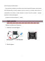
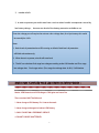
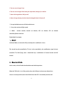
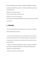
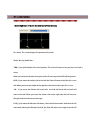
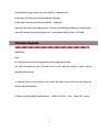
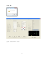
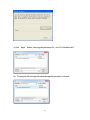
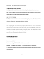
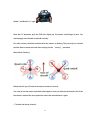
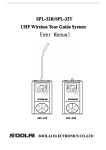
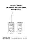
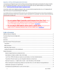
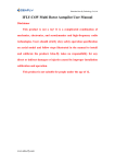
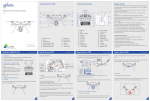
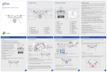
Hero-550 C6W—Flight Control System User Manual v1.0 1
Disclaimer Please read this disclaimer carefully and follow instructions on assembly and calibration contained in this manual. By using our product, you hereby agree to this disclaimer and signify that you have read the entire manual thoroughly. THIS PRODUCT IS NOT SUITABLE FOR PEOPLE UNDER THE AGE OF 18. This product is not a toy! It is a complicated combination of mechanics, electronics, aerodynamics and high-frequency radio technologies. Users should strictly obey safety operation specification on aerial model and follow steps illustrated in the manual to install and calibrate the product. Idea-Fly takes no responsibility for any direct or indirect damage(s) or injuries caused by improper installation, calibration and operation. Idea-Fly takes no responsibility for any direct or indirect damage(s) or injuries caused by installing/calibrating/flying this product when users are in situations including but not limited like drunk, taking drugs, dizziness, fatigue or any other cases no matter mentally or physically that would impair your ability. Idea-Fly takes no responsibility for any direct or indirect damage(s) or injuries caused by flying this product in inappropriate whether like windy (no more than gentle wind), rain, snow, hail, lightning or any natural disaster. Idea-Fly takes no responsibility for any direct or indirect damage(s) or injuries caused by using this product in inappropriate area like magnetic or radio interference area, government regulated no-fly zone or any other not permitted public or private areas. Idea-Fly takes no responsibility for any direct or indirect damage(s) or injuries caused by using this product assembled with parts NOT produced by Idea Fly, incomplete/incorrect assembly or Idea-Fly 2
product in aging or eroded condition. If any questions or problems occur before, during or after using Idea-Fly products, please contact local distributor/seller or Idea-Fly customer service for answers or assistance. Idea-Fly takes no responsibility for any direct or indirect damage(s) or injuries caused by customer’s improper operation or subjective misjudgment. Any other losses that are not Idea-Fly’s liability. Flight controller ****************************************************** Hardware Installation and Connection 1)Hardware Connection Diagram: 2)Port Description: 3
Interface Definition of Each Pin Interface function AIL Signal 5V GND To AIL of RC Rx ELE signal 5V GND To ELE of RC Rx THR signal 5V GND To THR of RC Rx RUD signal 5V GND To RUD of RC Rx CH5 signal 5V GND To CH5 of RC Rx CH6 signal 5V GND To CH6 of RC Rx POW 1.5V 5V GND Connect to 5V/2A DC module LED B G R LED Module USB Connect to PC M1 signal ESC output GND To ESC of Motor 1 M2 signal ESC output GND To ESC of Motor 2 M3 signal ESC output GND To ESC of Motor 3 M4 signal ESC output GND To ESC of Motor 4 M5 signal ESC output GND To ESC of Motor 5 M6 signal ESC output GND To ESC of Motor 6 Y1 signal 5V GND To gimbal Roll Servo Y2 signal 5V GND To gimbal pitch servo GPSR TXD 3.3V RXD To GPS port1(Red terminal) GPSB SDA GND SCL 4
TO GPS port 2(Black terminal) 3)Port Connection WHITE core wire is always the signal line, the RED core wire is positive; the BLACK core wire is ground 4) Notice: ①Support Quad-Rotor 1 and Quad-Rotor X As shown,M1-M4 correspond to the output ports(M1~M4) on the Main Controller(MC). The 5
direction of the arrow in diagram indicates the rotation direction of the motor/propeller. ② for Main controller : M1-M4 port should point to the nose of aircraft Main controller sides should be parallel to the aircraft body. ③ For GPS&COMPASS Module: The arrow should point to the nose direction of aircraft GPS /compass is sensitive to magnetic interfence, should be far away from any electronic devices. If your own mounting rod. make sure it is NOT magnetic. When you find the aircraft rotating or drifting, Please check the GPS module mounting orientation and then re-do the compass calibration. Installing and running on window ******************************************************************************** 6
① Turn on the transmitter, Switch 3 position switch to RTH mode. Then power on your aircraft. after 3 secs .Connect your aircraft and PC via Micro-USB cable. Notice : For firmware update : connect the USB cable first and then power on your aircraft. ②Run the assistant software” IDEAFLY-GCS.ex” (as shown) ③then click” open USB” 1.“Read” Button Download the current parameters, Usually, the default parameters are good enough for the flights. 2.“save “ Button 7
Edit the parameters : Click “save” Button” to save the newest parameters. (If this fails try several times) 3. ” Default” Button Different multi-rotors have different gains because of different motor KV ratings, ESC and propeller size.So default parameters isn’t for Hero-550. 4.Hero-550 parameters are shown below. ① Roll/Pitch sensitivity is used to adjust the compensation angle of the PTZ data for your Gimbal. (Note: range -127 to 127,You can enter a negative value to reverse the direction of compensation). ② Roll-Stab and Pitch-stab would affect the degree of command response in flight (range 0-255), Shake- Compens can increase stability but would decrease the sensitivity (range0-255). ③ Altitude/Distance Limit:The maximum height and distance allowed can be specified. min 10 meters. ④ Enter this to match the frequency of your gimbal servos. 50Hz, 250Hz, 333Hz and 400Hz servos are supported. 8
⑤ number of cells ⑥ In order to prevent your multi-rotor from a crash or other harmful consequences caused by low battery voltage ,there are two levels of low battery protection available to use. Enter the voltage per cell required to activate a low voltage alert, for a Lipo battery this would be normally be 3.65v. Note: 1、Both levels of protection have LED warning as default. Both levels of protection will blink red continuously. 2、When there is no power, aircraft will auto-land. 3、The MC can calculate final stage low voltage according to the Cell Number and First stage low voltage alert Final stage value= (First stage low voltage alert - 0.05v) * Cell Number Make sure Carefully read Lipo Battery Safety Guide : ********************************************************* Notice :LIPO Batteries and LIPO chargers CAN ignite and cause fire. These cautions MUST be followed 1. Never charge a LIPO battery if it is hot to the touch. 2. Never charge a damaged or broken LIPO Battery. 3. ONLY CHARGE ON A FIREPROOF SURFACE. 4. DO NOT CHARGE UNATTENDED. 9
5. Do not use or charge if wet. 6. Do not use or charge if the battery has expanded, enlarged, or swelled. 7. Never discharge below 3.0V per cell. 8. Never charge a battery that has been discharged below 3.0V per cell. ⑦ Set up the Maximum rate of climb and descent. ⑧ Set up the maximum flight speed. ⑨ Mode : Include manual, manual set altitude, GPS set altitude, GPS set altitude (head-free),Return and land. Flight Mode Description 1 、Manual In Manual Mode , the aircraft will fly normally and is stabilized in 3 axes. The aircraft may be controlled by TX, but is also controlled by the stabilization signal of main controller. The final flying state is determined by a combination of manual control and MC control. 2 、Manual set altitude In this mode, craft will hold the altitude but not hold the position. When the THR stick is in its 50% position the craft will hover in the current altitude but not at its current position (the craft will drift when the GPS is not locked), but the craft 10
can still be controlled manually. Left/right is controlled by the AILERON Stick, Up/Down controlled by the ELEVATOR stick, direction is controlled by the RUDDER stick, and height controlled by THR stick. If THR stick is 50%, craft will auto-hover; If THR stick is more than 50%, craft will fly upward; If THR stick is less than 50%, craft will descend. The Craft can fly to any altitude controlled by THR stick, and fly to any position controlled by the other sticks. 3 、GPS set altitude With GPS located (when satellites locked are more than 6) and CH5 is in position2, the aircraft will enter auto-hover mode. In this mode, the aircraft will hold its position and altitude. Your TX sticks should all be in the mid position. When THR stick is around the mid position the craft will hover in its current position, (The craft does not drift because GPS has locked) and also may controlled manually. Left/right is controlled by the AILERON Stick, Up/Down controlled by the ELEVATOR stick, direction is controlled by the RUDDER stick, and height controlled by THR stick. If THR stick is 50%, craft will auto-hover; If THR stick is more than 50%, craft will fly upward; 11
If THR stick is less than 50%, craft will descend. The Craft can fly to any altitude controlled by THR stick, and fly to any position controlled by the other sticks. 4 、GPS set altitude (head-free) The forward direction of a flying multi-rotor is the same as the nose direction, with GPS set altitude(head-free) mode, wherever the nose points, the forward direction has nothing to do with nose direction. 5、Return and Land With GPS locked (more than 6 satellites locked) and Motor arming done, the craft will record its home position. Push CH5 to position 3 to enter RTL (return and land) mode. In the Return and Land mode, the craft will return home and land automatically. After activation, you can only change to Stabilization Mode if you want to take over the flight controls. If you move from RTL to Auto Hover Mode, the aircraft will continue with the Return and Land process. On arrival at ‘Home’, the aircraft will begin to descend. At this time, the autopilot will allow you to take over AIL and RUD controls to adjust the landing site, but the THR cannot be controlled. The THR control is fully autonomous for descent and 12
landing. Altitude: If the craft is beyond 20 meters away from home position and below 20 meters altitude, the aircraft will ascend to 20 meters before initiating RTH when it enters RTL mode. If its height is more than 20 meters, the aircraft will maintain altitude during RTH. If the distance from home position is during 20 meters, the aircraft will maintain its previous altitude during RTH. Safety: Since RTH is fully autonomous and you cannot alter the flight path during RTH, to avoid accidents, it is not advisable to activate RTH too close to you or spectators. Also note to avoid sudden loss in altitude, the THR stick should be above its mid-point when you change the mode back from RTH to Stabilized Mode. Switch SWB to position3 from position2 to quit RTH mode. Mode1, Mode2, Mode 3 are for 3 position switch. Notice: you can assign any modes as you like. But please keep manual mode for position-1, When loose GPS signal during the flight, you can re-gain control of multi-rotor. 13
IMPORTANT 1、Make sure the TX is on first and the throttle stick is at the bottom. 2、DO NOT push the THR stick to the bottom during flying. 3、DO NOT switch to auto-fly mode until the craft is stable in manual mode. 4、Switch to manual mode if craft meets an emergency situation in auto-fly mode. ⑩ F/S option(failsafe) Choose one method for your failed-safe function: (Auto RTH and Land, Auto Land and Auto Hover are the options) Notice
:
Auto RHT: Before takeoff ,Current position of mutli-rotor will be saved as home point By MC automatically when you push the throttle stick first time after 6 or more GPS satellites are found. Auto land: the aircraft will land . Auto-hover: the aircraft will hover in the air. If your transmitter doe snot support Fail-safe, the fail-safe function will not work when the communication between MC and transmitter is disconnected. 14
Fail/Safe Checking ************************************************************************************ A、Check that Flight Modes change on TX command Check Flight Modes via the Configuration software ‘Flight Mode’: Assuming your GPS module is connected; check whether switching between all working modes is working normally. For example: Switch SWB at position1 to position 2, the PC GCS "data" page should show your TX status as "Manual", Change CH5 to position 2 for Auto Hover and so on. If flight mode does not change when you toggle the switches please check your hardware connections or RC Transmitter setup. B、Fail Safe (F/S) Checking SWITCH OFF the RC Transmitter whilst the main controller is still powered on; the ‘Flight-Mode’ should switch to display "Return and Land", the throttle stick indicator should be in the middle and displayed in GREEN. If it does not, please setup the fail-safe (F/S) again. It is strongly recommended to use the default F/S. ⑩ C6W supported “Quad 4+” ,Quad 4X” 15
RC calibration ***************************************************** 1.Select right type of mode that your transmitter was set. For shown, This screen displays the position of the sticks. Slides Moving Definition:
THR: If you pull throttle stick to low position. The slide will move to low position. And craft is down, When you move the throttle stick up,the slide will move up,craft will lift off the ground. RUD :If you move the rudder stick to the left, the slide will move to the left, this is nose left. When you move the rudder to the right,the slide move to the right, this is nose
AIL:If you move the Aileron stick to the left,the slide will move left and craft will move to the left. When you move the aileron stick to the right ,the slide will move to the right and craft will move to the right.
ELE:If you move the Elevator stick down,the slide will move down. And the craft will move back, Moving the Elevator Stick up, the Slide will move to the right and craft will 16
move forward(away from you)
Note:If the slides are moving opposite from your stick movements direction, Check REV/NOR of your transmitter. 2. Command sticks calibration. Click ‘Adjust Transmitter’ button Click ‘OK’ and move your transmitter stick within 5 Seconds to their maximum positions as shown in the diagram: Note:finish the calibration before this diagram disappear. For check: 17
Check that the display of each stick shows that TX is calibrated well. On the left is the THR stick and Rudder (Mode 2 depicted). On the right is the aileron and Elevator (Mode 2 depicted). When all sticks are in the middle position , All slides should become GREEN, any other position shows RED except for when the throttle stick is at the bottom when it shows as YELLOW. Firmware Upgrade ******************************************************** IMPORTANT: Note: For safety, please remove all the propellers before upgrading firmware. You may download the latest firmware and assistant tool from Idea-Fly website before upgrading the firmware. (1) Connect the MC to the computer with a Mini USB cable. Power the MC and put bring the throttle stick to the bottom. (2) After 3 sec, Open the MC Setup Software “ IDEAFLY-GCS.exe”, Click “Open USB” button . 18
(3) Click “OK” (4) Click “Select Firmware” button 19
(5) Click “Open” button, select upgrade procedure file“s4v2-CYF-20140508-v051” (6) The program will auto-upgrade when the upgrade procedure is selected. 20
(7) Power-off the autopilot when it says “upgrade successful”. Quit the firmware upgrade software . Check:re-power on your aircraft. after 3 secs .Connect your aircraft and PC via Micro-USB cable. Adjustment Outdoors ******************************************************* 1 、Compass Calibration. IMPORTANT: (1)When using the aircarft for the first time, the GPS/COMPASS must be calibrated before arming the motors. (2)Compass calibration does not need to be done every time you fly but should be done when components are moved or if the aircraft flies in unexpected ways, like in circles, for example. (3) ALWAYS carry out this calibration outdoors, far away from metallic objects (cars, radio towers, power lines etc.). There are 3 steps to follow: 21
1. Horizontal calibration 2. Vertical calibration 3. Save GPS/COMPASS data. Keep aircraft horizontal;then power on the aircraft. waiting 10 secs for resetting Horizontal Calibration. Quickly flip SWB switch from manual mode to GPS mode and back to manual mode for more than 3 times. LED indicator will be turn on solid Green. You have entered Horizontal Calibration. Hold Hero-550 horizontal and rotate 3 circles. During this process, please keep green light is constant green. Note: ENSURE that the GREEN LED remains ON during this procedure. If it turns OFF, it means the aircraft is not horizontal. Adjust the position until the GREEN LED is back ON and continue with the rotation. Quickly flip SWB switch from manual mode to GPS mode and back to manual mode for more 22
than 3 times. LED indicator will be turn on solid green You have entered Vertical Calibration Carefully rotate the aircraft 3 times as shown below, always keeping the aircraft nose down. Note :Ensure the GREEN LED remains ON during the turn. If the LED turns OFF, adjust position until the GREEN LED is back ON and continue with the rotation. Save GPS/COMPASS data. The flight controller will start to save current data. During this process. LED indicator will be solid green.LED turns off, meaning the calibration is finished. After completing the above maneuvers, Quickly flip SWR switch from manual mode to GPS mode and back to manual mode for more than 3 times. place the aircraft on the ground. Main controller will enter the magnetic recording . During this process. LED indicator will be solid green. LED turns off, meaning the calibration is finished. Takeoff/ Landing procedures Start the motor /take off Note: Motor arming will fail if the GPS module is not connected. Enable the “Combined-Stick-Command” (CSC) for motor arming as shown below: To arm, push the left-hand stick to the far left and extreme bottom, the right stick to the far right and to the bottom. 23
(Mode 1 and Mode 2) is /\ type. After the CSC operation, push the THR stick slightly up. The motors should begin to turn. You need to apply more throttle to take off normally. For safety reasons, the Main controller locks the motors on landing. They can only be re-armed to allow them to rotate and work after carrying out the “arming” procedure. Motor Mixer Checking Before take-off, you still need to check your motor mix control. You need to arm the motors and check what happens when you advance the throttle stick, if the four motors rotate at the same speed this means the motor balance is good. 1. To check the aileron channel: 24
slightly push the aileron stick to the left, motor M4 should rotate immediately, the other three motors should keep still. Push the aileron stick to the right slightly, motor M2 should rotate immediately the other three motors should keep still. 2. Check the elevator channel: According to the aircraft symmetry it should be similar to checking the aileron channel. Push the elevator stick up slightly, motor M3 should start to rotate . Now slightly pull the elevator stick down and motor M1 should start to rotate immediately. 3. After landing, the motors will stop. Move your THR stick to the bottom, 5 seconds later the motors will lock. Arm the motors to restart flying. LED Indicator Interpretation: ************************************************* Note: 1 Before you flight, make sure LED indicator blink green 3 times 2 (Keep SWB switch at GPS hover position2) 25
3 the motor will stop if we don’t push the throttle stick with 5 secs. and you will need to re-start the motors. 4 During the flight, Never pull the throttle stick to the lowest position,Motor will be locked 5 yellow light: aircraft is abnormal。This probably caused by Attitude error,you could repower aircraft ,then start the motor. ( it is normal for this to happen only occasionally),If LED is solid yellow,Please check GPS connection. 6 throttle stick is sensitive. When you switch GPS mode to manual mode, you’d better push throttle stick to avoid to loose height. Shenzhen Idea-Fly Technology Co., Ltd
Tel: +0086 755 61267080
Fax:+0086 755 61267081
website: http://www.idea-fly.com/
Address:6 Floor, A3 Building, Zhong Yu Guan Industrol Park,No.1014, Zhong Yu Guan Street,Long
Hua New District,Shen Zhen City, Guang Dong Province, China
26