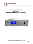
1
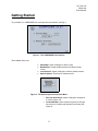
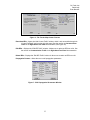
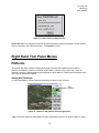
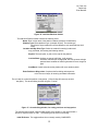
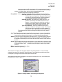
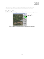
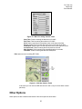
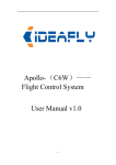
Dr. Frank Lee
David Lally
Evan Boucher
COMPOSER User Manual
June 2009
Contents
I.
II.
III.
IV.
Getting Started…………………………………………….....Pg. 1
The Map Interface……………………………………………Pg. 2
Toolbar Menus………...……………………………………...Pg. 3
Right Hand Tool Panel Menus……….…………………..…Pg. 11
1
Dr. Frank Lee
David Lally
Evan Boucher
Getting Started
To get started, run COMPOSER.exe. It will open the main interface (See Fig.1).
Figure 1 - The COMPOSER main interface
The available options are:
•
•
•
•
Select Map: Opens a dialogue to select a map
New Mission: Creates a blank mission and opens the map
screen
Load Scenario: Opens a dialogue to select a prebuilt scenario
Special Options: These are for advanced users
Figure 2 - The Special Options Drop Down Menu
o Run from Auto-Script: Opens a dialogue to navigate to
a custom script to run
o Create New Map: Opens a wizard to guide you through
the process for creating and importing a new map (See
Figure 6)
2
Dr. Frank Lee
David Lally
Evan Boucher
The Map Interface
After setting up these options the map interface is displayed. There are two main areas to start, the Toolbar
menus at the top, and the Right-Hand Tool Panel.
Figure 3 - The Main Map Interface
Toolbar Menus
The following is a breakdown of all the tools that are accessible through the tool bars at the top of the
Composer GUI
FILE
New Scenario – Displays the startup screen for the user to begin a new scenario.
Import Scenario(s) – Allows the user to import a saved scenario into the current scenario.
Load Alternate Map - Allows the user to swap the map used in the scenario.
Save Scenario - Prompts the user to save the current scenario in the default directory.
Take Snap-Shot – Takes a screen capture of the Composer program. It saves a .ppm file to the
default directory (Composer_X.XX\support_files)
Preferences – Allows the user to edit preferences.
3
Dr. Frank Lee
David Lally
Evan Boucher
The user can choose the coordinate system. Click the current system to view a
drop down menu. The choices are:
•
•
Degrees - Latitude/Longitude
Map-Relative Meters
You can also change the color of the icons. Click on the current color to view a
drop down menu with alternative color choices. The choices are:
•
•
•
•
•
•
•
•
Black
White
Light-Gray
Dark-Gray
Violet
Blue
Yellow
Orange
Figure 4 - The Edit Preferences Window
Exit - Exits the Application
4
Dr. Frank Lee
David Lally
Evan Boucher
EDIT
Enter New Channel – Displays the “Set Channel” window.
Edit Existing Channel – Displays the “Edit Existing Channel” window. Through this window, the
user can choose an existing channel from a list to edit or delete. One can also create a
new channel from this window. Both of these options bring the user to the “Set Channel”
window.
Radio Type Definition – Displays a reference window that allows the user to look up and
compare specs on different radio types. Select a radio from the list, and then there are
many different parameters that can be viewed (See Figure 5).
Figure 5 - The Radio Type Definition Windows
Undelete Platform – Allows a user to bring back a deleted platform.
Edit WayPoints – Allows a user to select a platform from a list to edit its way-points. This menu
is also accessible through the “Platforms >Edit” option on the right side panel, as well as
through double-clicking a way-point on the map. See the section on Platforms in the
Right Hand Tool Panel documentation (Figure 20).
Delete WayPoints – Deletes selected waypoints
Edit Map Setup – Allows one to create a new custom map. It uses the following steps:
•
•
•
•
Prompts to create a name.
Prompts to enter map coordinates (in degrees) to set up the north, south, east, and west
boundaries of the map.
Directions on using “step2.html” and an image editing program to save the map are displayed here.
It then prompts the user to compress the final map image.
5
Dr. Frank Lee
David Lally
Evan Boucher
Figure 6 - The Terrain Map Creator Process
Enter New IERs – Opens the “Add Comms Traffic” window, which is also accessible through the
“CommsTraff>Add” option on the right side panel. See the section on Communication
Traffic in the Right Hand Tool Panel documentation (See Figure 30).
Edit IERs – Displays the “Edit IER Traffic” window. It allows one to select an IER from a list. See
the section on Communication Traffic in the Right Hand Tool Panel documentation.
Delete IERs – Displays the “Edit IER Traffic” window. It allows one to select an IER from a list.
Propagation Params – Allows the user to edit propagation parameters.
Figure 7 - Edit Propagation Parameters Window
6
Dr. Frank Lee
David Lally
Evan Boucher
VIEW
Coordinate Units- Allows the user to change the coordinate units of the map. The options are:
• Kilometers
• Miles
• Nautical Miles
• Degrees, Minutes, Seconds - Latitude/Longitude
• Fract. Deg - Latitude/Longitude
Hide/Show Grids – Toggles the coordinate grid on and off
Hide/Show All Paths – Toggles the paths displayed on the map on and off
Filter Tracks – Allows a user to filter displayed tracks based on a time period within the
simulation
View Last Results – Displays the “Results Summary” window from the most recently run
simulation
Figure 8 - An example of a summary of plotted results
Set Propagation Algorithm –Allows the user to set the method for calculating the propagation.
The available options are:
•
•
•
Distance Only (1/R^3)
Longley-Rice Irregular Terrain Model
TIREM
Propagation Coverage Animation – Activates propagation coverage animation.
Propagation Animation Style – Change the style of the propagation animation to be either
smooth or by the grid of the map.
7
Dr. Frank Lee
David Lally
Evan Boucher
Link Strength Animation – Creates visual tries to any strength animation that is on screen.
Link Traffic Animation – Creates visual tries to Traffic information that is on screen.
Enlarge Icons – Increases the size of the icons on the map.
Reduce Icons – Decreases the size of the icons on the map.
Display Elevation Image – Displays the contour lines of the topographic map
Remove/Display Contour-Map Overlay – Removes the contour-map overlay when active.
Toggles the contour lines of the topographic map on and off
Disable/Enable Tool-tips – Toggles tool-tips on and off. Tool-tips allow a user to hover over an
option with the mouse in order to receive information on what that option does.
Edit Viewing Properties – Allows the user to chance the contour step amount and the color of
the contour map.
TOOLS
Opens the drop-down menu for options regarding the various tools of Composer.
Options: (This option appeared to be currently disabled.)
Play Tracks: Opens the menu for previewing moves. This option is also available on the control
panel under “Preview Moves.”
Figure 9
- The Play Tracks menu with Play, Stop, and Close commands.
Start Time: Start time of the simulation preview.
End Time: End time of the simulation preview.
Speed: The speed at which the simulation preview will take to process.
Play: Begins to play the simulation preview.
8
Dr. Frank Lee
David Lally
Evan Boucher
Stop: Ends the simulation preview.
Plot Results: Opens an additional drop-down menu for plotting the results of a simulation on a
graph.
Figure 10 - An example of the graph interface which can be changes with the following options.
The following are different methods of plotting the information on a graph:
•
•
•
•
•
•
•
•
•
•
•
Comms Traffic Requested vs. Time
Comms Traffic Transmitted vs. Time
Comms Traffic Received at Destinations vs. Time
Comms Traffic Requested (Source+Relay) vs. Time
Comms Traffic Transmitted (Source+Relay) vs. Time
Comms Traffic Received (Source+Relay) vs. Time
Comms Traffic Corrupted vs. Time
Comms Traffic Waiting in Queues vs. Time
Mean Routing Latency vs. Time
Vehicles Moving vs. Time Histogram
Vehicle Way-Points vs. Time Histogram
Run a Script: Opens a directory search in which the user can locate and run a script for Composer
(typically .BAT filetypes).
Run from Auto-Script: Opens a direction search in which the user can locate and run an autoscript for Composer (typically in an XML file type).
Emitter Coverage Contour: Opens a menu to plot emitter coverage contours.
Select a radio from the list.
9
Dr. Frank Lee
David Lally
Evan Boucher
Figure 11 - Plot Emitter Coverage Contour Menu
Radio (Organize by Propagation or Signal-Strength)
Set the Notional Receiver Height in the field below the list.
Show Emitter Coverage Contour: Plots the Emitter Coverage Contour
Point-to-Point Propagation: Opens a two-column dialogue box featuring a list of transmitters and
receivers to select “From” and “To.” Distance, Propagation Loss (dB), and Signal Strength
(dBm/meter^2) information list will fill in upon selection from the list. Select Profile when complete.
Figure 12 - Point-to-Point Propagation Menu
10
Dr. Frank Lee
David Lally
Evan Boucher
MOUSE
Opens the drop-down menu that presents different mouse control types.
The current state of mouse control is featured in blue on the top right of the main interface.
Figure 13 - The mouse menu opens a number of options for navigating the viewport. The blue
text shows what state the mouse is currently in.
Ident/Edit Way-Points or Pan: Changes the mouse control type to identify/editing way-points and/
or panning around the map (clicking anywhere else on the map will allow the user to pan with the
mouse.)
Drag Waypoints: Changes the mouse control type to be able to drag way-points around the map.
Drag Whole Tracks: Changes the mouse control type to drag whole tracks around the map.
Terrain Elev. Sample: The mouse samples the terrain from the selected area.
Terrain Profile Graphs: The mouse profiles the terrain as graphed data when selected.
Propagation Coverage: The mouse will show propagation coverage when an area is selected.
HELP
Opens the drop-down menu for options regarding ‘Help’.
11
Dr. Frank Lee
David Lally
Evan Boucher
Figure 14 - About This Tool Dialogue Box
About This Tool: This dialogue box features the latest information regarding Composer’s version number,
purpose, developer, and contact information. Click Dismiss to close.
Right Hand Tool Panel Menus
Platforms
This section discusses controls for adding and editing information about platforms with scenarios.
Platforms correspond to vehicles or sites that contain radios. Vehicles may be ground, air, water, etc.
(example: HumVee). Multiple radios may be attached to a given platform. Platforms have positions on the
map, such as latitude and longitude.
Adding New Platforms:
To add a new platform, click the Platforms Add button, as show in figure 15 below.
Add
Platform
Figure 15 - Button to add platform from top-right panel.
Add: This button opens the dialog window to add a new platform instance, as shown in figure 16, below.
12
Dr. Frank Lee
David Lally
Evan Boucher
Figure 16 - Add New Platform window.
The Add New Platform window contains the following items:
Name: Enter unique name of the platform instance (example: Charlie-Bravo).
Platform Type: Select platform’s type. (example: Stryker) The vehicle-type
specifies the object rendered in the visualizations, such as the Mil-Std. 2525
Icons.
Location and Way-Point Type: Select the method for entering location and
way- point data, from among the following choices:
Explicit: The exact point, or path, on the map for the platform.
Corridor/Rand: Outlines an area of traffic-flow. It will generate
numerous vehicles upon a single path. One can generate a single
path and have hundreds of vehicles generated to move along that
path.
Area/Rand: Creates a box where the platform will move randomly within.
Enter Position or Way-points: Completes the first dialog and sequences
to the next set of steps, for entering coordinate information.
The next step is to enter the position or way-points. (A fixed entity will have only an initial
way-point.) The second dialog is shown in figure 17 below:
Figure 17 - Second dialog window, for setting positions and way-points.
The selected entry method is written under the title of the window. In the case pictured, it
shows As explicit Position or Path. The following are the items on the dialog.
Initial ID Known: This toggle attribute is not currently used by COMPOSER.
13
Dr. Frank Lee
David Lally
Evan Boucher
It toggles whether the ID of the platform will be considered to be known by
other entities at the start of the scenario. It is usually used for adversary,
coalition, or civilian entities, and may affect simulated detection and
automated responses in campaign simulations.
Entry Method: Click to choose the method of entering coordinates from the following:
Click Map, by Speed: Set speed between each way-point, and
click the map to enter positions. Way-point arrival time is
automatically calculated based on speed and distance.
This is generally the fastest and easiest method.
Click Map, by Time: Set arrival time for each way-point. The
speed is automatically calculated based on time and
distance. You must type a new arrival time and click a
position on the map for each way-point entered. Each
successive time must be later than the previous one.
Type Values Manually: Enter the coordinates and times by
typing them instead of clicking on the map. This is useful
when the way-point coordinates have been supplied to
the operator. But it is generally the most tedious method.
The subsequent form boxes will change according to the entry method
selected.
Start Time: Enter the time when the platform first appears in the scenario. Normally this
is the start of the scenario, which is time 0, or 0:00:00:00. Times can be entered
in seconds from the start of the scenario, or in Days:Hours:Minutes:Seconds.
Altitude: Enter the height of the platform above the terrain. For ground objects, leave this
set to zero. This is generally relevant to airborne platforms. A new altitude can
be entered for each way-point, so aircarft can be made to take-off, climb, descend,
or land.
Speed: Enter the speed for this way-point segment. A new speed can be entered for each
segment between way-points. This specifies the speed from the current way-point
to the next (if there is one). A different entry will display if another Entry Mode is
selected.
Back: Jumps back to the previous dialog.
Cancel: Aborts this path entry.
The method for accepting each way-point depends on the Entry Method. For the Click-Map
methods, the way-point is entered by clicking the map. For the Manual method, the way-point
is accepted by clicking the Next button that appears in that mode.
After entering the way-point, a window for entering the next way-point, if any, or completing the
path appears as shown in figure 18.
Figure 18 - Dialog window, for entering next way-point.
14
Dr. Frank Lee
David Lally
Evan Boucher
Again, enter the next way-point, according to the previously selected method. When done
entering all the way-points for a platform path, then click the Done button at the bottom.
Editing Existing Platforms:
To edit information about an existing platform, click the Platforms Edit button, as show in figure 19 below.
Edit
Platform
Figure 19 - Button on top-right front panel for editing platform information.
15
Dr. Frank Lee
David Lally
Evan Boucher
Edit: This button opens a window for editing platform information, as shown in figure 20.
Figure 20 - Window for selecting platform to edit.
Select a platform to edit from the list. Platforms are listed by name, start-time, number of tracks,
kind, and display status. You can select a platform and then press the Edit button. Or, you can
double-click the platform entry. Once selected, you can also Delete or just Hide its display, by
clicking the appropriate button or toggle, respectively, on the bottom ledger. You can also Hide
all paths, and then turn-on just specific ones.
Once you select a platform to edit, you get the following dialog window shown in figure 21.
You can also get to this same window by double-clicking on any vertex of a platform's path.
Figure 21 - Window for editing platform to information.
The top of this window shows the name of the platform being edited.
16
Dr. Frank Lee
David Lally
Evan Boucher
From this window, you can change the platform's type, the color of its path-display on the map,
edit or add attribute values, toggle its display status, edit way-point values, or view and edit any
radios attached to it.
Radios
This section discusses controls for adding and editing radios.
Add: Opens a menu for adding a radio.
Figure 22 – The Add Radios Button is on the Right panel
Figure 23 - Window for adding radios.
Platform: Field for designating the platform the radio will be assigned to (Note: the
17
Dr. Frank Lee
David Lally
Evan Boucher
Platforms button on the right will reveal a list of options from preexisting platforms (See
Figure 24).
Figure 24 – drop-down window for selecting existing platform.
Name: Field for entering in the name of your radio.
Type: Field for designating the type of radio. The models button will present a menu for
type selection.
SubNet: Field for entering a SubNet. The Channels button will present a list of channels to
be entered as the SubNet.
Wire Connect: Field for entering the wired connection. The Radios button will present a
list of radios to be selected (See Figure 25).
18
Dr. Frank Lee
David Lally
Evan Boucher
Figure 25 – drop-down window for selecting a radio type.
Other Radio Attributes: Opens a new menu for adding additional attributes to radios.
Figure 26 – The menu for adding additional radio attributes.
OK: Completes the radio addition.
Edit: Opens a menu for editing your existing list of radios.
Figure 27- The Add Radios Button is on the Right panel
Select a radio from the list. Once selected, you may Edit or Delete a radio.
Edit: The edit option opens a menu for adjusting the settings of a previously added radio.
This menu is similar to that when adding a new radio.
Delete: Deletes a radio from the list and the map.
19
Dr. Frank Lee
David Lally
Evan Boucher
Figure 28– Edit Radios Menu
Communication Traffic
This section discusses controls for adding and editing Communication Traffic.
Add: Opens a menu for adding Comms Traffic.
Figure 29 - Add New Comms Traffic
IER: The list of required fields for adding Comms Traffic.
20
Dr. Frank Lee
David Lally
Evan Boucher
Figure 30 – Menu for adding Comms Traffic
Start Time: Field for entering the start time in D:H:M:S.
End Time: Field for entering the end time in D:H:M:S.
Kind: Select a type from the drop down menu to the right of the field.
Source: Select a type from the drop down menu to the right of the field.
Destination: Select a type from the drop down menu to the right of the field.
Arrival Period: Field for entering the arrival period in seconds.
Msg Duration: Field for entering the message duration in seconds.
Data Rate: Field for entering the data rate in Kbytes/S.
Edit: Opens a menu for editing IER Traffic.
Figure 31 - Edit New Comms Traffic
In the menu you can select an IER and choose to edit it, only if one has been created
previously.
Other Options
Other options are also located on the bottom of the control panel as seen below:
21
Dr. Frank Lee
David Lally
Evan Boucher
Figure 32 – Misc. Right Panel Options
Hide Paths: This button will hide all of the paths currently visible on the map.
Navigation Controls: Quick-access navigation controls are listed on the bottom of the control panel.
Zoom-In: This button allows the user to zoom in on the map. Zooming in displays different level of details.
For example, road and terrain information may appear at closer zoom levels that was not visible at the
default view.
Zoom-Out: This button will allow the user to zoom out on the map.
Preview Moves: Opens the menu for previewing the moves as set up on the map.
Start Time: Start time of the simulation preview.
End Time: End time of the simulation preview.
Speed: The speed at which the simulation preview will take to process.
Play: Begins to play the simulation preview.
Stop: Ends the simulation preview.
Run Sim: Begins to run the simulation. A progress bar will appear to visualize the remaining time.
Following the simulation, the user will be presented with the resulting summary of the simulation.
3D Visual: This option will load the 3D visual which is based on the 2D simulation.
Directional Controls (<,^,v,>): Pressing these buttons will allow the user to navigate (pan) around the
map.
Exit: This option will exit Composer.
22