1
Power HawkTM Series 900
Console Reference Manual
0830060-120
January 2006
CAUTIONARY NOTICE
While the manufacturer has attempted to detail in this manual all areas of possible danger to personnel in conjunction
with the use of this equipment, personnel should use caution when installing, checking out, operating and servicing
this equipment, especially when power is on. As with all electronic equipment, care should be taken to avoid
electrical shock in all circuits where substantial currents or voltages may be present either through design or short
circuit. Caution should be observed in hoisting equipment, especially regarding large structures during installation.
The Manufacturer is specifically not liable for any damage or injury, arising out of a worker’s failure to follow the
instructions contained in this manual, or in his failure to exercise due care and caution in the installation, operation,
checkout and service of this equipment.
PROPRIETARY DATA
This document, the design contained herein, the detail and invention are considered proprietary to Concurrent Computer Corporation. As the property of Concurrent Computer Corporation it shall be used only for reference, contract
or proposal work by this corporation, or for field repair of Concurrent products by Concurrent Computer Corporation
service personnel, customers, or end users.
Copyright 2006 by Concurrent Computer Corporation. All rights reserved. This publication or any part thereof is
intended for use with Concurrent products by Concurrent Computer Corporation personnel, customers, and end–
users. It may not be reproduced in any form without the written permission of the publisher.
The information contained in this document is believed to be correct at the time of publication. It is subject to change
without notice. Concurrent Computer Corporation makes no warranties, expressed or implied, concerning the
information contained in this document.
To report an error or comment on a specific portion of the manual, photocopy the page in question and mark the
correction or comment on the copy. Mail the copy (and any additional comments) to Concurrent Computer Corporation, 2881 Gateway Drive, Pompano Beach, FL 33069. Mark the envelope “Attention: Publications Department.”
This publication may not be reproduced for any other reason in any form without written permission of the publisher.
Night Hawk, Power Hawk, PowerStack II and PowerMAX OS, are trademarks of Concurrent Computer Corporation
Synergy, VAFQ, VAFS. VYFD, VGM5 and VSS4 are trademarks of Synergy Microsystems, Inc.
UNIX is a registered trademark of the Open Group.
Printed in U. S. A.
Revision History:
Date:
Level:
Effective With:
Original Release
Previous Release
Previous Release
Current Release
July 2003
February 2004
November 2004
January 2006
000
100
110
120
New Product Release of Series 900
PowerMAX 6.1
PowerMAX 6.2
PowerMAX 6.3
Preface
Scope of Manual
This manual describes the console for Concurrent Computer Corporation’s Power Hawk
Series 900 system. This manual provides information on how to use the console to debug
the system. Series 900 systems use the following single board computers (SBC) manufactured by Synergy Microsystems, Inc.
Concurrent
System Platform
Motherboard
Type
Number of
Processors
Power Hawk 910
VYFD -Single
1
VME 6U
Power Hawk 920
VYFD - Dual
2
VME 6U
Power Hawk 940
VAFQ - Quad
4
VME 6U
Form Factor
Structure of Manual
This manual consists of a title page, this preface, a master table of contents, three chapters,
three local tables of contents for the chapters, two appendixes, and an index. A brief
description of the chapters and appendixes follows:
• Chapter 1 explains where the console fits in a system and describes the
hardware of the console.
• Chapter 2 describes what occurs during system initialization and the
console interface.
• Chapter 3 contains an alphabetical listing of the console debugging
commands. Each command listing contains the purpose of the command,
its syntax, an explanation of the command parameters, and examples of the
command syntax and usage.
• Appendix A is a quick reference guide that lists the console commands and
their meanings, as well as an explanation of the command parameters.
• Appendix B lists the possible error codes that may appear executing
console commands. There is also a short description of the error and a
possible cure to the problem.
The index has an alphabetical list of all paragraph formats, character formats, cross
reference formats, table formats, and variables.
iii
Power Hawk Series 900 Console Reference Manual
Syntax Notation
The following notation is used throughout this guide:
italic
Books, reference cards, and items that the user must specify
appear in italic type. Special terms may also appear in italic.
bold
User input appears in bold type and must be entered exactly as
shown. Names of directories, files, and commands also appear in
bold type.
list
Operating system and program output such as prompts and
messages and listings of files and programs appears in list type.
[]
Brackets enclose command options and arguments that are
optional. You do not type the brackets if you choose to specify
such option or arguments.
Vendor Documentation
Synergy commercial off-the-shelf (COTS) documentation applicable to the various
Synergy Single Board Computers (SBC), are listed below. You may contact your local
Synergy sales office to purchase Synergy manuals not provided with the system. See the
table below for a list of Synergy manual names and document numbers.
Manual Name
Synergy
Document
Number
Raptor DX VMEbus Dual G4, Dual PMC & StarFabric PowerPC SBC 02-0426/UG-VYFD-<REV>
User Guide
iv
MantaQX3/VAFQ VMEBus Quad G4 Single PMC and Star Fabric
PowerPC SBC User Manual
815138 - Version <VER>
Synergy Microsystems STAR User Guide
03-0072/UG-STAR-<REV>
Synergy Microsystems ASTRix User’s Guide
03-0076/UG-ASTX-<REV>
Chapter 0
Contents
Preface . . . . . . . . . . . . . . . . . . . . . . . . . . . . . . . . . . . . . . . . . . . . . . . . . . . . . . . . . . . . . . . . . . . . . . . . . . . . . . . .
iii
Chapter 1 Introduction to the Console
Overview of Console . . . . . . . . . . . . . . . . . . . . . . . . . . . . . . . . . . . . . . . . . . . . . . . . .
1-1
System Initialization . . . . . . . . . . . . . . . . . . . . . . . . . . . . . . . . . . . . . . . . . . . . . . . . .
STAR Initialization. . . . . . . . . . . . . . . . . . . . . . . . . . . . . . . . . . . . . . . . . . . . . . .
ASTRix initialization . . . . . . . . . . . . . . . . . . . . . . . . . . . . . . . . . . . . . . . . . . . . .
STAR/ASTRix Automatic initialization. . . . . . . . . . . . . . . . . . . . . . . . . . . . . . .
Console Initialization. . . . . . . . . . . . . . . . . . . . . . . . . . . . . . . . . . . . . . . . . . . . . . . . .
System Boot . . . . . . . . . . . . . . . . . . . . . . . . . . . . . . . . . . . . . . . . . . . . . . . . . . . .
Console Interface . . . . . . . . . . . . . . . . . . . . . . . . . . . . . . . . . . . . . . . . . . . . . . . .
System Entry to Console . . . . . . . . . . . . . . . . . . . . . . . . . . . . . . . . . . . . . . . . . .
Reset/SMI . . . . . . . . . . . . . . . . . . . . . . . . . . . . . . . . . . . . . . . . . . . . . . . . . . . . . .
LEDs. . . . . . . . . . . . . . . . . . . . . . . . . . . . . . . . . . . . . . . . . . . . . . . . . . . . . . . . . .
Lamp Test Feature . . . . . . . . . . . . . . . . . . . . . . . . . . . . . . . . . . . . . . . . . . . .
Front Panel LEDs . . . . . . . . . . . . . . . . . . . . . . . . . . . . . . . . . . . . . . . . . . . .
2-1
2-1
2-5
2-5
2-7
2-9
2-11
2-11
2-12
2-13
2-13
2-13
Chapter 2 Startup
Chapter 3 Console Debugging Commands
Summary of Commands . . . . . . . . . . . . . . . . . . . . . . . . . . . . . . . . . . . . . . . . . . . . . .
Syntax Conventions . . . . . . . . . . . . . . . . . . . . . . . . . . . . . . . . . . . . . . . . . . . . . .
Command Format. . . . . . . . . . . . . . . . . . . . . . . . . . . . . . . . . . . . . . . . . . . . . . . .
Command Specifier. . . . . . . . . . . . . . . . . . . . . . . . . . . . . . . . . . . . . . . . . . .
Data Size and Format . . . . . . . . . . . . . . . . . . . . . . . . . . . . . . . . . . . . . . . . .
Global Options . . . . . . . . . . . . . . . . . . . . . . . . . . . . . . . . . . . . . . . . . . . . . .
Local Options . . . . . . . . . . . . . . . . . . . . . . . . . . . . . . . . . . . . . . . . . . . . . . .
Numeric Values . . . . . . . . . . . . . . . . . . . . . . . . . . . . . . . . . . . . . . . . . . . . . .
Address Value . . . . . . . . . . . . . . . . . . . . . . . . . . . . . . . . . . . . . . . . . . . . . . .
Command Manipulators . . . . . . . . . . . . . . . . . . . . . . . . . . . . . . . . . . . . . . .
Command Editing. . . . . . . . . . . . . . . . . . . . . . . . . . . . . . . . . . . . . . . . . . . . . . . .
Console Commands . . . . . . . . . . . . . . . . . . . . . . . . . . . . . . . . . . . . . . . . . . . . . . . . . .
3-1
3-2
3-5
3-5
3-5
3-6
3-6
3-6
3-7
3-7
3-9
3-9
Appendix A Console Command Summary . . . . . . . . . . . . . . . . . . . . . . . . . . . . . . . . . . . . . . . . . . . . . . .
A-1
Appendix B Error Codes . . . . . . . . . . . . . . . . . . . . . . . . . . . . . . . . . . . . . . . . . . . . . . . . . . . . . . . . . . . . . . .
B-1
Index . . . . . . . . . . . . . . . . . . . . . . . . . . . . . . . . . . . . . . . . . . . . . . . . . . . . . . . . . . . . . . . . . . . . . . . . . . . . . . . . . Index-1
v
Power Hawk Series 900 Console Reference Manual
List of Illustrations
Figure 2-1.
Figure 2-2.
Figure 2-3.
Figure 2-4.
Reset and SMI Toggle Switch on VYFD . . . . . . . . . . . . . . . . . . . . . . .
Reset Pushbutton on VAFQ . . . . . . . . . . . . . . . . . . . . . . . . . . . . . . . . . .
Front Panel LEDs for VYFD . . . . . . . . . . . . . . . . . . . . . . . . . . . . . . . . .
Front Panel LEDs for VAFQ . . . . . . . . . . . . . . . . . . . . . . . . . . . . . . . . .
2-12
2-12
2-14
2-14
Table 2-1. Description of Reset and SMI . . . . . . . . . . . . . . . . . . . . . . . . . . . . . . . . .
Table 2-2. Description of Front Panel LEDs. . . . . . . . . . . . . . . . . . . . . . . . . . . . . . .
Table 3-1. Console Debugging Commands - Summary . . . . . . . . . . . . . . . . . . . . . .
Table 3-2. Console Special Key Functions . . . . . . . . . . . . . . . . . . . . . . . . . . . . . . . .
Table 3-3. Effect of pboot on Boot Process . . . . . . . . . . . . . . . . . . . . . . . . . . . . . . .
Table 3-4. General–Purpose Registers . . . . . . . . . . . . . . . . . . . . . . . . . . . . . . . . . . .
Table 3-5. Processor Registers Accessed via p Command . . . . . . . . . . . . . . . . . . . .
Table 3-6. y Command Flag Bits . . . . . . . . . . . . . . . . . . . . . . . . . . . . . . . . . . . . . . .
Table A-1. Command Parameter Definitions . . . . . . . . . . . . . . . . . . . . . . . . . . . . . .
2-13
2-15
3-3
3-9
3-24
3-32
3-41
3-63
A-9
List of Tables
vi
1 tartup
1
Introduction to the Console
Overview of Console . . . . . . . . . . . . . . . . . . . . . . . . . . . . . . . . . . . . . . . . . . . . . . . . .
1-1
1
Chapter 1Introduction to the Console
1
1
1
Overview of Console
The console for the Power Hawk 900 Series system allows the operator to initialize the
system and perform certain diagnostic procedures. An overview of this product is
provided in the following paragraphs.
The Power Hawk Series 900 platform uses two monitor ROM programs called STAR
(Self Test And Run) and ASTRix (Advanced Self Test Reboot Initialize eXecute) that
provide basic board initialization, configuration and diagnostic capability. The STAR utility will execute whenever the system is powered up or reset. STAR and ASTRix are used
to configure the basic system as well as loading the initial boot image from distribution
media. The individual commands used in STAR and ASTRix are documented in the Synergy Microsystem STAR User Guide, and the Synergy Microsystem ASTRix User Guide
respectively. The user should be familiar with STAR and ASTRix commands found in
these manuals.
The Power Hawk 900 Series system normally begins execution in the STAR program that
is located in flash memory. STAR/ASTRix can be configured to automatically boot the
Power Hawk 900 Series system console off of the appropriate boot media. The console is
provided in a ‘loadable’ format at the front of bootable media. TheSTAR/ASTRix internal
ROM bootstrap code reads the console into RAM, where it then relocates itself to higher
memory locations and begins execution.
The exact mode of operation depends upon the operator action and NVRAM settings
during the start-up. If the operator interrupts the boot sequence or has set up NVRAM
setting to prevent the boot sequence from auto starting, a console prompt will be output
and console commands may be used for debugging or system start-up as described later in
this manual. If the boot is not interrupted, the system bootstrap is fully automatic and the
PowerMAX OS kernel will be brought up to the multi-user system level specified in the
file /etc/inittab .
1-1
Power Hawk 900 Console Reference Manual
1-2
2
Startup
System Initialization . . . . . . . . . . . . . . . . . . . . . . . . . . . . . . . . . . . . . . . . . . . . . . . . .
STAR Initialization. . . . . . . . . . . . . . . . . . . . . . . . . . . . . . . . . . . . . . . . . . . . . . .
ASTRix initialization . . . . . . . . . . . . . . . . . . . . . . . . . . . . . . . . . . . . . . . . . . . . .
STAR/ASTRix Automatic initialization. . . . . . . . . . . . . . . . . . . . . . . . . . . . . . .
Console Initialization. . . . . . . . . . . . . . . . . . . . . . . . . . . . . . . . . . . . . . . . . . . . . . . . .
System Boot . . . . . . . . . . . . . . . . . . . . . . . . . . . . . . . . . . . . . . . . . . . . . . . . . . . .
Console Interface . . . . . . . . . . . . . . . . . . . . . . . . . . . . . . . . . . . . . . . . . . . . . . . .
System Entry to Console . . . . . . . . . . . . . . . . . . . . . . . . . . . . . . . . . . . . . . . . . .
Reset/SMI . . . . . . . . . . . . . . . . . . . . . . . . . . . . . . . . . . . . . . . . . . . . . . . . . . . . . .
LEDs. . . . . . . . . . . . . . . . . . . . . . . . . . . . . . . . . . . . . . . . . . . . . . . . . . . . . . . . . .
Lamp Test Feature . . . . . . . . . . . . . . . . . . . . . . . . . . . . . . . . . . . . . . . . . . . .
Front Panel LEDs . . . . . . . . . . . . . . . . . . . . . . . . . . . . . . . . . . . . . . . . . . . .
2-1
2-1
2-5
2-5
2-7
2-9
2-11
2-11
2-12
2-13
2-13
2-13
2
Chapter 2 Startup
2
2
2
System Initialization
System initialization can be separated into four distinct areas: STAR Initialization,
ASTRix Initialization, Console Initialization and System Boot. These occur as described
in the following paragraphs. The screen examples shown below are typical. They may
vary due to particular system settings and/or firmware versions.
STAR Initialization
STAR (Self Test And Run) is the monitor ROM that provides basic board initialization,
diagnostic and a boot capability. STAR capabilities and commands are documented in the
Synergy Microsystems S.T.A.R. User Guide
A Power Hawk 900 board as shipped from the factory is likely on powerup to stop at the
STAR prompt. STAR is a ROM-based program from which standalone board diagnostics
can be executed. An example of a STAR boot sequence from a VYFD board power on is
shown below.
--- Curtiss-Wright Controls, Embedded Computing S.T.A.R. Diagnostics ----- Rev: 1.01.42 Oct 19 2004 11:12:30 --Reset Cause: VME Reset
User Switch: 0x00
X: CPU 0 running - Temp: -1 - L3 initialized
Y: CPU 1 running - Temp: -1 - L3 initialized
Board: VYFD-C ECO:
Number of CPUs
:
CPU Type
:
BackSide Cache Sz :
Memory Bank Size :
Memory Size
:
Shared Console
:
PCI0 Config
:
PCI1 Config
:
6
2
7457
2MB
256MB
512MB
Yes
768MB
768MB
Special Mod.
Bus Speed (MHz)
Rev
Cache Ratio
Number of Banks
Type
I2C found (hex)
Start Address
Start Address
:
:
:
:
:
:
:
:
:
0
Serial# : 1501782
133
BootLoc : Boot Flash
0102
Speed
: 1000 MHz
6:1
2
H-Bridge: Discovery-B
SDRAM, CL=3, Flow-Thru
4D
0x80000000
0xC0000000
Bus IdSel ConfigAdr VendID DevID Rev Class Sub Int Vendor
Part
___________________________________ PCI0 ___________________________________
0 20
80005000 1000
0021 01
01
00 10
LSI
Ultra160
___________________________________ PCI1 ___________________________________
1 11
80010800 10E3
0000 02
06
80 12
Tundra
Universe2
2-1
Power Hawk Series 900 Console Reference Manual
An example of VAFQ board power on is shown below.
--- Curtiss-Wright Controls, Embedded Computing S.T.A.R. Diagnostics ----- Rev: 1.01.50 Oct 31 2005 14:37:10 --Reset Cause: VME Reset
X:
Y:
Z:
W:
CPU
CPU
CPU
CPU
0
1
2
3
running
running
running
running
-
Temp:
Temp:
Temp:
Temp:
User Switch: 0x00
-1
-1
-1
-1
Board: VAFQ-A ECO:
3
Number of CPUs
:
4
CPU Type
:
7457
BackSide Cache Sz :
2MB
Memory Bank Size : 512MB
Memory Size
: 1024MB
Shared Console
:
Yes
PCI0 Config
: 768MB
PCI1 Config
:
1GB
-
L3
L3
L3
L3
Reset Count: 0
initialized
initialized
initialized
initialized
Special Mod.
Bus Speed (MHz)
Rev
Cache Ratio
Number of Banks
Type
I2C found (hex)
Start Address
Start Address
:
:
:
:
:
:
:
:
:
0
Serial# : 3044576
100. BootLoc : Boot Flash
0102
Speed
: 1000 MHz
6:1
NAND
: none
2
H-Bridge: Discovery III
SDRAM, CL=2.0, Flow-Thru
4C
0x80000000
0xB0000000
Bus IdSel ConfigAdr VendID DevID Rev Class Sub Int Vendor
Part
___________________________________ PCI0 ___________________________________
0 12
80001000 9902
0002 02
06
80 10
StarGen
Path Route
0 14
80002000 1000
0021 01
01
00
8
LSI
Ultra160
0 14.1 80002100 1000
0021 01
01
00
9
LSI
Ultra160
___________________________________ PCI1 ___________________________________
1 13
80011800 10E3
0000 02
06
80 16
Tundra
Universe2
1 18
80014000 104C
8023 00
0C
00 23
TI
TSB43AB22
The user can change various parameters that effect the way STAR boots using the config
command. An example of the config command is shown below. STAR initialization commands can be automated using a post script file which is discussed later in this chapter.
An example of the config command on VYFD is shown below:
STAR0> config
Enter a new value or a return to skip, ‘-’ to back up, or ‘.’ to exit:
**** BOOT Configs (reset when defaults set) ****
Port 0 baudrate:
9600 =
Port 1,2,3 baudrate:
9600 =
Share console port:
Y =
PCI Enum powerup delay (milliseconds): 1007 =
Enable quiet boot mode:
N =
Enable ASTRix autoboot:
N =
Enable “post” script:
Y =
Skip PCI Enumeration:
N =
Skip PMC Configuration:
N =
L1 Miss Queue Depth (1,3,6):
3 =
L3 Size L3 (1, 2 MB):
2 =
Enable Built-in self tests:
1= at powerup only
2= at all hard resets
3= at all resets
0 =
**** USER Configs (unchanged when defaults are set) ****
Board serial number:
0x1501782 =
Target IP address:
129.134.32.67 =
Host IP address:
129.134.30.26 =
2-2
Startup
Print Boot Banner:
Y =
Init mem ECC:
N =
Legacy Mode Input:
N =
Enable ChangeLog Message:
Y =
Clear SysFail:
0= Before “post” script
1= After “post” script
0 =
Copy NVRAM from Flash on power-up:
0= None
1= BOOT parameters (last 12KB)
2= BOOT and FILE area (last 32KB)
3= ALL NVRAM (128KB)
0 =
PCI 0 Start Addr (ex. 0x80000000):
0x80000000 =
PCI 0 Size (ex. 0x30000000 (768GB)):
0x30000000 =
PCI 1 Start Addr (ex. 0xB0000000):
0xC0000000 =
PCI 1 Size (ex. 0x10000000
(256MB)): 0x30000000 =
Hit Enter to finish (or exec, pci, flash, nopci, spec):
=
STAR0>
An example of the config command on VAFQ is shown below:
STAR0> config
Enter a new value or a return to skip, ‘-’ to back up, or ‘.’ to exit:
**** BOOT Configs (reset when defaults set) ****
Port 0 baudrate:
9600 =
Port 1,2,3 baudrate:
9600 =
Share console port:
Y =
PCI Enum powerup delay (milliseconds): 1007 =
Enable quiet boot mode:
N =
Enable ASTRix autoboot:
N =
Enable “post” script:
Y =
Skip PCI Enumeration:
N =
Skip PMC Configuration:
N =
L3 Size L3 (1, 2 MB):
2 =
Enable Built-in self tests:
1= at powerup only
2= at all hard resets
3= at all resets
0 =
**** USER Configs (unchanged when defaults are set) ****
Board serial number:
0x1502944 =
Target IP address:
129.134.32.68 =
Host IP address:
129.134.30.26 =
Print Boot Banner:
Y =
Init mem ECC:
N =
Legacy Mode Input:
N =
Enable ChangeLog Message:
Y =
Clear SysFail:
0= Before “post” script
1= After “post” script
0 =
Copy NVRAM from Flash on power-up:
0= None
1= BOOT parameters (last 12KB)
2= BOOT and FILE area (last 32KB)
3= ALL NVRAM (128KB)
0 =
PCI 0 Start Addr (ex. 0x80000000):
0x80000000 =
PCI 0 Size (ex. 0x30000000 (768GB)):
0x30000000 =
PCI 1 Start Addr (ex. 0xB0000000):
0xB0000000 =
PCI 1 Size (ex. 0x10000000
(256MB)): 0x40000000 =
2-3
Power Hawk Series 900 Console Reference Manual
Hit Enter to finish (or exec, pci, flash, nopci, spec):
=
STAR0>
The items shown by the config command are documented in the Synergy Microsystems
S.T.A.R. User Guide.
The STAR config command's PCI Memory Space parameters directly control the range
and size of PCI Memory Space used by the PowerMAX OS kernel. It is highly recommended that you set these config command parameters to the following default values
before attempting to boot a PowerMAX OS kernel:
PCI 0 Start Addr (ex. 0x80000000): 0x80000000 =
PCI 0 Size (ex. 0x40000000 (1GB)): 0x30000000 =
PCI 1 Start Addr (ex. 0x80000000): 0xB0000000 =
PCI 1 Size (ex. 0x10000000 (256MB)): 0x40000000 =
The PCI Bus 0 Memory Space, from 0x80000000 to 0xAFFFFFFF, is used by PMC
devices, and the PCI Bus 1 Memory Space, from 0xC0000000 to EFFFFFFF, is used for
VMEBus A32 address space.
Note that unlike previous Power Hawk platforms that used kernel tunables to control the
layout of VME A32 address space, Power Hawk Series 900 platforms directly and
dynamically use these STAR config parameter PCI Bus 1 settings for determining the
layout of VME A32 address space.
After the PowerMAX OS kernel boots successfully, you may want to modify these default
settings if you happen to have a need for more (or less) VME A32 address space or PMC
device PCI Memory Space.
When modifying these PCI parameter values, the following restrictions should be followed:
• The PCI 0 and PCI 1 Memory Space ranges may not overlap.
• The PCI 0 Start Addr parameter MUST remain set to a value of
0x80000000.
• The ending address of the PCI 1 Memory Space range MUST be
0xEFFFFFFF.
NOTE
If the PowerMAX OS kernel detects that the PCI 0 start address is
not 0x80000000, or that the ending address for PCI 1 Memory
Space is not 0xEFFFFFFF, the kernel will halt and return back to
the console processor.
For example, to change the A32 address range to 0xA0000000 – 0xEFFFFFFF and the
PCI Bus 0 Memory Space range to 0x80000000 – 0x9FFFFFFF, set the STAR config
parameters to the following values:
PCI 0 Start Addr:
PCI 0 Size:
PCI 1 Start Addr:
PCI 1 Size:
2-4
0x80000000
0x20000000
0xA0000000
0x50000000
Startup
ASTRix initialization
ASTRix is a flash based diskless operating system based on Linux. It is designed to boot
quickly and provide users with tools to create NVRAM post scripts, boot the PowerMAX
console software from disk, and set up automatic STAR/ASTRix/PowerMAX Console
initialization.
To start ASTRix from STAR enter:
STAR0>astrix
The prompt issued by ASTRix is an asterisk, e.g. “*”.
When the ASTRix prompt (*) appears the set of ASTRix commands documented in the
Synergy Microsystems ASTRix User Guide may be used. STAR and ASTRIX are used to
set up the initialization and configuration of the Power Hawk Model 920/940. Users familiar with general unix commands will find ASTRix relatively easy to use.
To return to STAR from the ASTRix prompt, simply enter the command:
* star
STAR0>
STAR/ASTRix Automatic initialization
Using STAR and ASTRix the user can set up automatic initialization to load the PowerMAX Console software from the flash file system. The use of the STAR config command,
and other ASTRix commands enables this function. Follow the procedure below to load
the PowerMAX Console software from the boot disk and place it into Flash Filesystem 3.
At that point the PowerMAX Console can be booted from the flash file system.
1. From the STAR prompt.
STAR0> config
Enter a new value or a return to skip, '-' to back up, or '.' to exit:
**** BOOT Configs (reset when defaults set) ****
Port A baudrate:
9600 =
Port B baudrate:
9600 =
(115200 on VAFQ)
Share console port:
PCI Enum powerup delay (milliseconds):
Enable quiet boot mode:
Enable ASTRix autoboot:
Enable "post" script:
Skip PCI Enumeration:
Skip PMC Configuration:
L1 Miss Queue Depth (1,3,6):
L3 Size L3 (1, 2 MB):
Enable Built-in self tests:
1= at powerup only
2= at all hard resets
3= at all resets
Y =
1007 =
N =
N =
Y =
N =
N =
3 =
2 =
0 =
**** USER Configs (unchanged when defaults are set) ****
Board serial number:
0x1301892 =
2-5
Power Hawk Series 900 Console Reference Manual
Target IP address:
Host IP address:
Print Boot Banner:
Init mem EDC:
Clear SysFail:
0= Before "post" script
1= After "post" script
Copy NVRAM from Flash on power-up:
0= None
1= BOOT parameters (last 12KB)
2= BOOT and FILE area (last 32KB)
3= ALL NVRAM (128KB)
129.134.32.80 =
129.134.32.81 =
Y =
N =
Legacy Mode Input:
Enable ChangeLog Message:
PCI 0 Start Addr (ex. 0x80000000):
PCI 0 Size (ex. 0x40000000 (1GB)):
PCI 1 Start Addr (ex. 0x80000000):
PCI 1 Size (ex. 0x10000000 (256MB)):
Hit Enter to finish:
N =
Y =
0x80000000
0x30000000
0xC0000000
0x30000000
=
0 =
0 =
=
=
=
=
NOTE
If the “Target IP address” field contains 0.0.0.0 the board will use
DHCP to obtain the IP address. If DHCP is not configured, an IP
address must be entered for automatic initialization to complete.
STAR0> astrix
2. On Power Hawk 940 systems, it may be necessary to add the Boot Flash
Write Enable Jumper (JP01 Pins 9-10) in order to allow writing to the boot
flash. This must be done before proceeding; otherwise, you may not be
able to successfully complete the following steps.
3. In vi, insert the following lines in the file /nvram/update.flash:
* vi /nvram/update.flash
scsi-drivers
dd if=/dev/sda1 of=/cp1
ffsw /cp1 3
boot 5 -n ffs3:cp1 -s -c
:wq
* chmod 755 /nvram/update.flash
* /nvram/update.flash
WARNING
The use of /dev/sda1 in the dd command above implies the first
partition on the first drive. If the system disk is not the first disk,
then the use /dev/sd<c>1, where c is the character for the “nth”
disk to use. The number 1 denotes the partition on the disk where
the use of /dev/sda (without the partion number) specifies the
entire disk. Failure to follow this convention will have indeterminate results.
2-6
Startup
4. To enable ECC. (Skip this step if ECC is not to be enabled.)
In vi, insert the following lines in the file /nvram/post:
* vi /nvram/post
if (cpuid == 0) {
printf("\nInitializing and Enabling SDRAM ECC\n") ;
serialok=0 ;
imedc 0 0 1 ;
serialok=1 ;
sleep 1 ;
boot 5 ;
}
:wq
Go to Step 4.
5. Perform this step only if ECC is NOT to be enabled.
In vi, insert the following lines in the file /nvram/post:
* vi /nvram/post
if (cpuid == 0) {
sleep 2 ;
boot 5 ;
}
:wq
NOTE
The sleep command is to give the user time to abort the startup of
the console processor from STAR.
6. Start the PowerMAX Console, enter
* star
to return to STAR, and immediately boot the console processor.
Use <ctrl>c to abort boot and stay in STAR.
Console Initialization
NOTE
The following assumes the PowerMAX OS has been previously
installed. If the OS has not been installed on your system, please
refer to the appropriate version of the Power Hawk Series 900
PowerMAX OS Release Notes (Pubs No. 0891089-6.n) for
installation instructions.
2-7
Power Hawk Series 900 Console Reference Manual
The PowerMAX OS Console startup sequence for a VYFD board appears below:
--- Curtiss-Wright Controls, Embedded Computing S.T.A.R. Diagnostics ----- Rev: 1.01.42 Oct 19 2004 11:12:30 --Reset Cause: VME Reset
User Switch: 0x00
X: CPU 0 running - Temp: -1 - L3 initialized
Y: CPU 1 running - Temp: -1 - L3 initialized
Board: VYFD-C ECO:
Number of CPUs
:
CPU Type
:
BackSide Cache Sz :
Memory Bank Size :
Memory Size
:
Shared Console
:
PCI0 Config
:
PCI1 Config
:
6
2
7457
2MB
256MB
512MB
Yes
768MB
768MB
Special Mod.
Bus Speed (MHz)
Rev
Cache Ratio
Number of Banks
Type
I2C found (hex)
Start Address
Start Address
:
:
:
:
:
:
:
:
:
0
Serial# : 1501782
133
BootLoc : Boot Flash
0102
Speed
: 1000 MHz
6:1
2
H-Bridge: Discovery-B
SDRAM, CL=3, Flow-Thru
4D
0x80000000
0xC0000000
Bus IdSel ConfigAdr VendID DevID Rev Class Sub Int Vendor
Part
___________________________________ PCI0 ___________________________________
0 20
80005000 1000
0021 01
01
00 10
LSI
Ultra160
___________________________________ PCI1 ___________________________________
1 11
80010800 10E3
0000 02
06
80 12
Tundra
Universe2
STAR0> boot 8
Y: CPU 1 standing by.
PowerMAX_OS Synergy Console (6.3-20051122), located at 01faf000 to 02000000.
- Board vyfd-c eco 6 pl 0, 512MB, 2 1000MHz PPC-7457s each with 512KB L2 Cache
and 2MB L3 Cache, 133MHz bus, sitting in vme slot 1 (autodetected).
- CPU 0 stats: chip major rev 1, minor rev 2, chipmaker IBM.
- Boot parms: fd -sw dsk(0,3,0,0,0), y0, p -sw boot 80, p aboot 0.
CPUs 0 1 up.
Type ‘?’ for help.
#0>
The PowerMAX OS boot sequence on VAFQ board is as follows:--- Curtiss-Wright Controls, Embedded Computing S.T.A.R. Diagnostics ----- Rev: 1.01.50 Oct 31 2005 14:37:10 --Reset Cause: VME Reset
X:
Y:
Z:
W:
CPU
CPU
CPU
CPU
0
1
2
3
running
running
running
running
-
Temp:
Temp:
Temp:
Temp:
User Switch: 0x00
-1
-1
-1
-1
Board: VAFQ-A ECO:
3
Number of CPUs
:
4
CPU Type
:
7457
BackSide Cache Sz :
2MB
Memory Bank Size : 512MB
Memory Size
: 1024MB
Shared Console
:
Yes
2-8
-
L3
L3
L3
L3
Reset Count: 0
initialized
initialized
initialized
initialized
Special Mod.
Bus Speed (MHz)
Rev
Cache Ratio
Number of Banks
Type
I2C found (hex)
:
0
Serial# : 3044576
:
100. BootLoc : Boot Flash
: 0102
Speed
: 1000 MHz
:
6:1
NAND
: none
:
2
H-Bridge: Discovery III
: SDRAM, CL=2.0, Flow-Thru
: 4C
Startup
PCI0 Config
PCI1 Config
:
:
768MB
1GB
Start Address
Start Address
: 0x80000000
: 0xB0000000
Bus IdSel ConfigAdr VendID DevID Rev Class Sub Int Vendor
Part
___________________________________ PCI0 ___________________________________
0 12
80001000 9902
0002 02
06
80 10
StarGen
Path Route
0 14
80002000 1000
0021 01
01
00
8
LSI
Ultra160
0 14.1 80002100 1000
0021 01
01
00
9
LSI
Ultra160
___________________________________ PCI1 ___________________________________
1 13
80011800 10E3
0000 02
06
80 16
Tundra
Universe2
1 18
80014000 104C
8023 00
0C
00 23
TI
TSB43AB22
STAR0>
Y: CPU
Z: CPU
W: CPU
boot 8
1 standing by.
2 standing by.
3 standing by.
PowerMAX_OS Synergy Console (6.3-20051113), located at 01faf000 to 02000000.
- Board vafq-a eco 3 pl 0, 1024MB, 4 1000MHz PPC-7457s each with 512KB L2 Cache
and 2MB L3 Cache, 100MHz bus, sitting in vme slot 2 (autodetected).
- CPU 0 stats: chip major rev 1, minor rev 2, chipmaker IBM.
- Boot parms: fd -sw dsk(0,3,0,0,0), y0, p -sw boot 80, p aboot 0.
CPUs 0 1 2 3 up.
Type ‘?’ for help.
At this point the console waits at most five seconds before continuing. If an exclamation
point (!) is entered the console automatically starts the boot sequence without waiting the
full five seconds. If, however, the operator enters the pound sign (#) during those five
seconds, the system boot procedure is cancelled and the console prompt ‘#>’ is displayed.
When the #> prompt is displayed, any command described in Chapter 3 of this manual
may be entered. Of particular importance is the fb command which causes the boot program to execute and load system programs, and the pboot register command, which specifies the boot options.
The paboot register may also be changed to lengthen or shorten the time, on future autoboots, the console will wait before autobooting a PowerMAX OS. If paboot is set to zero,
autobooting is disabled and the console prompt ‘#>’ is displayed immediately upon
console startup.
System Boot
If the console system boot procedure was not cancelled, then the system boot mode is
entered.
The boot sequence on a VYFD board is:
PowerMAX_OS Synergy Console (6.3-20051122), located at 01faf000 to 02000000.
- Board vyfd-c eco 6 pl 0, 512MB, 2 1000MHz PPC-7457s each with 512KB L2 Cache
and 2MB L3 Cache, 133MHz bus, sitting in vme slot 1 (autodetected).
- CPU 0 stats: chip major rev 1, minor rev 2, chipmaker IBM.
- Boot parms: fd -sw dsk(0,3,0,0,0), y0, p -sw boot 80, p aboot 0.
CPUs 0 1 up.
2-9
Power Hawk Series 900 Console Reference Manual
The boot sequence on a VAFQ board is:
PowerMAX_OS Synergy Console (6.3-20051113), located at 01faf000 to 02000000.
- Board vafq-a eco 3 pl 0, 1024MB, 4 1000MHz PPC-7457s each with 512KB L2 Cache
and 2MB L3 Cache, 100MHz bus, sitting in vme slot 2 (autodetected).
- CPU 0 stats: chip major rev 1, minor rev 2, chipmaker IBM.
- Boot parms: fd -sw dsk(0,3,0,0,0), y0, p -sw boot 80, p aboot 0.
CPUs 0 1 2 3 up.
Type ‘#’ to cancel boot, ‘!’ to boot immediately (5 seconds).....
ncr0)0...2.3.......................
Set Run Mode
CPUs 0 1 2 3 up.
dsk(0,3,0,0,0)/.
dsk(0,3,0,0,0)/stand/boot
pboot 00000080
PowerMAX OS Boot Loader
Boot
: /stand/unix
3048712+415479+913045 start 0x6000
symbol table loaded
Concurrent PowerMAX_OS Release 6.3
Global Memory: 1073410048 bytes
Initialize I/O level 0 interface: SYS.PCI0
Initialize I/O level 1 interface: SYS.PCI1.VME0
dmac:
Tundra Universe DMA Controller (Revision 2)
vp driver initialized
ncr0:
on SYS.PCI0
ncr1:
on SYS.PCI0
mve0:
100BaseT FDX
mve0:
on MV64460
mve1:
1000BaseT FDX
mve1:
on MV64460
SDRAM ECC support is enabled.
The system is coming up.
Please wait.
SCSI device @ID 0 on ncr adapter 0: disk
SCSI device @ID 2 on ncr adapter 0: disk
SCSI device @ID 3 on ncr adapter 0: disk
Checking root filesystem
Node: curtis
Checking /var filesystem
Checking file systems:
File system check complete.
UX:hrtconfig: INFO: /dev/rrtc/0c0 configured as HRT callout queue RTC
The system is ready.
The system’s name is curtis.
Welcome to Synergy PowerMAX_OS Release 6.3
Console Login:
2-10
Startup
The ‘Boot params:’ line in the above example gives real console commands that were
executed for you when the console started up. They came from the area of RAM reserved
for the console. See Chapter 3, Console Debugging Commands, for detailed description of
these and all the other console commands.
Console Interface
Unlike STAR/ASTRix, the PowerMAX console understands several PowerMAX OS filesystem types, and hence is able to reach into and load into memory whatever files the console user desires to be loaded (see the fl, fr and fb commands). However, the console
understands only one file format - that of a raw, executable image. That is, it is able to load
a file bit-for-bit into a default or designated memory location, and if to be executed, will
jump to the load location of the file, in effect assuming that is the first instruction which
is to be executed. If the desired file to be executed is not in this format, then a helper program that is in this format must first be loaded. One such program is provided with a PowerMAX OS installation: /stand/boot. This bootstrap understands the ELF(3E) file format
created by the PowerMAX OS cc(1) command. Since the PowerMAX OS kernel is in ELF
format, /stand/boot must be used when loading and executing a PowerMAX OS kernel.
/stand/boot is loaded and executed automatically by the fb command. The fB command is
identical to fb except that it allows the operator to specify a different /stand/boot file
(assuming one exists). The fl command allows the operator to load a /stand/boot-like file
but not automatically execute it. The fc command gives the operator ls(1)-like listings of
directory contents on the root filesystem.
/stand/boot will automatically boot and execute /stand/unix, the actual PowerMAX OS
kernel, unless it has been told to ask for an alternate filename to boot, via a pboot flags
setting.
The console makes breakpoint, trace, and other debug services available once a
PowerMAX OS kernel, or standalone program such as /stand/boot, has started execution.
System Entry to Console
Any entry from a program to the console is performed via exceptions. These exceptions
consist of breakpoint, trace, halt, and error. Upon entry to the console, the current context,
system and user registers, and operating modes are saved and the #> prompt is output.
Commands described in Chapter 3 of this manual may then be input. Control is also
transferred to the console if the operator enters the sequence ‘<CR>~i’ at the system
console while the PowerMAX OS kernel is in operation.
Control may be returned to the executing program by entering the r (Run) command. Note
that if File (f) commands are used, it is no longer possible to return to the operating system
at the point it entered the console.
2-11
Power Hawk Series 900 Console Reference Manual
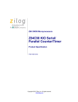
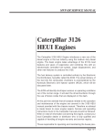
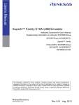
Reset/SMI
The VYFD motherboard has a RESET and SMI toggle switch. The VAFQ motherboard
has a reset pushbutton only. See Figure 2-1, Figure 2-2 and Table 2-1 for more information.
User LEDs (0-7)
CPU Reset Toggle-right for RESET; left for SMI
CPU Halt/Run & PCI0 Status LEDs
Status LEDs
Figure 2-1. Reset and SMI Toggle Switch on VYFD
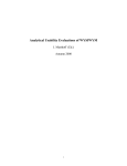
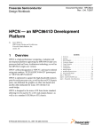
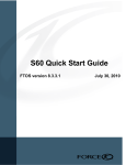
Reset pushbutton
Figure 2-2. Reset Pushbutton on VAFQ
2-12
Startup
Table 2-1. Description of Reset and SMI
RESET
Pushing the reset switch to the right (910/920) or pushing the reset
pushbutton (940) asserts a board-level RESET which:
• Resets the CPU(s).
• Resets all on-board components that have such a function and
clears all on-board control registers.
• Asserts a VME RESET if the board is serving as the System
Controller.
SMI
(910/920 only) Pushing a switch to the left asserts an SMI interrupt to
the CPUs.
LEDs
The VYFD and VAFQ each have front panel LEDs (see Figure 2-2 and Figure 2-4) for
quick indication of board activity.
Lamp Test Feature
During board level reset, all LEDs are illuminated. To confirm proper operation of the
LED indicators, observe the LEDs while pressing the CPU reset switch to the right. LEDs
remain lit for as long as the reset switch is held in the reset position.
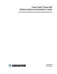
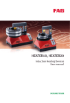
Front Panel LEDs
Figure 2-3 shows the front panel LEDs for the VYFD board. Figure 2-4 shows the front
panel LEDs for the VAFQ board.
Refer to Table 2-2 for a description of the function of the front panel LEDs on both
boards.
2-13
Power Hawk Series 900 Console Reference Manual
Figure 2-3. Front Panel LEDs for VYFD
Figure 2-4. Front Panel LEDs for VAFQ
2-14
Startup
Table 2-2. Description of Front Panel LEDs
User LEDs
The eight User LEDs indicate application events.
0-7
Software-programmable LEDs are controlled by the USER LED registers. They indicate the
current operating mode of the board as defined by the software currently running.
CPU Halt/Run LEDs
The X, Y, Z, and W dual-colored LEDs indicate the run status of the indicated processor.
LED Label
X, Y
(VYFD)
X, Y, Z, W
(VAFQ)
Indication
Green (Run)
Red (Halt)
Flickers green in response to PowerPC bus activ- Lights red when CPU has halted.
ity by the indicated CPU. If not on, indicates
CPU is not executing bus cycles as it executes
instructions in cache or waits for an interrupt.
Green (Run)
Red (Halt)
Flickers green in response to PowerPC bus activ- Lights red when CPU is reset or halted
ity. Lights yellow-orange for prolonged bus idle (check stopped).
(>150 ms).
Status LEDs
The Status dual-colored LEDs indicate various status items.
LED Label
Indication
FAIL
Red
When on, indicates a condition that caused the CPU to reset (VMEbus SysRst\ line or the front
panel RESET toggle).
During normal operation, the system boot software clears this condition shortly after RESET.
SC
Green
When on, indicates System Controller function assumed by board.
VME
Green (VME Master)
Red (VME Slave)
Flickers green in response to VME Master activ- Flickers red in response to VME Slave
ity. When the VMEbus interface is idle, lights up activity. (See Note 1)
green on the last release-on-request (ROR)
VMEbus master to have used the bus.
PCI
Green (PCI Bus)
Red (PCI Expansion)
Flickers green in response to PCI bus (master) Flickers red in response to PCI expansion
activity.
(PMC) activity. (See Note 1)
Continued on next page
2-15
Power Hawk Series 900 Console Reference Manual
Table 2-2. Description of Front Panel LEDs (Cont.)
Ethernet LEDs
Two LEDS on the Ethernet RJ-45 connector indicate Ethernet port status.
VYFD
Green
Link OK - lit when 10Base-T/100Base-TX cable is properly plugged into a functioning Ethernet
network and onboard software has initialized the Ethernet interface.
Yellow
Receive Activity - Flickers whenever data is being received. If connected to a repeater-type hub
instead of a switch-type hub, may still flicker even when the board is not the intended recipient
since packets sent over the network to other nodes will also be sent to this board.
VAFQ
Link
Lights when the port is plugged into a functioning Ethernet network and software has initialized
the Ethernet interface. Also indicates the Ethernet operating mode as follows:
• Slow blink (2 Hz) for 10Base-T
• Fast blink (4 Hz) for 100Base-T
• Solid ON for 1000Base-TX (Gigabit Ethernet)
Activity
Flickers whenever data is being received. If connected to a repeater-type hub instead of a
switch-type hub, may still flicker even when the board is not the intended recipient since packets
sent over the network to other nodes will also be sent to this board.
Note 1. Dual color green/red LED typically lights up yellow-orange as the two conditions quickly alternate.
2-16
3
Console Debugging Commands
Summary of Commands . . . . . . . . . . . . . . . . . . . . . . . . . . . . . . . . . . . . . . . . . . . . . .
Syntax Conventions . . . . . . . . . . . . . . . . . . . . . . . . . . . . . . . . . . . . . . . . . . . . . .
Command Format. . . . . . . . . . . . . . . . . . . . . . . . . . . . . . . . . . . . . . . . . . . . . . . .
Command Specifier. . . . . . . . . . . . . . . . . . . . . . . . . . . . . . . . . . . . . . . . . . .
Data Size and Format . . . . . . . . . . . . . . . . . . . . . . . . . . . . . . . . . . . . . . . . .
Global Options . . . . . . . . . . . . . . . . . . . . . . . . . . . . . . . . . . . . . . . . . . . . . .
Local Options . . . . . . . . . . . . . . . . . . . . . . . . . . . . . . . . . . . . . . . . . . . . . . .
Numeric Values . . . . . . . . . . . . . . . . . . . . . . . . . . . . . . . . . . . . . . . . . . . . . .
Address Value . . . . . . . . . . . . . . . . . . . . . . . . . . . . . . . . . . . . . . . . . . . . . . .
Command Manipulators . . . . . . . . . . . . . . . . . . . . . . . . . . . . . . . . . . . . . . .
Command Editing. . . . . . . . . . . . . . . . . . . . . . . . . . . . . . . . . . . . . . . . . . . . . . . .
Console Commands . . . . . . . . . . . . . . . . . . . . . . . . . . . . . . . . . . . . . . . . . . . . . . . . . .
3-1
3-2
3-5
3-5
3-5
3-6
3-6
3-6
3-7
3-7
3-9
3-9
3
Chapter 3 Console Debugging Commands
3
3
3
Summary of Commands
A summary of the console command set is shown in Table 3-1. This command set not only
supports booting, but also the debugging of standalone programs (including the PowerMAX OS kernel) through the use of breakpoint services and the ability to examine and
change registers and memory locations on command.
When the console is ready for a new command, it will display one of several prompts:
#>
is displayed for uniprocessor systems.
#0>
is the most common display for multiprocessor systems. The numeric value (0) is the CPU
the console is running on (called the master CPU), AND the CPU whose registers will be
examined, modified, or stepped by default when no CPU is specified on the command line
(the attentive CPU).
#0:1>
This prompt is displayed when the master CPU (0) is different from the attentive CPU (1).
By default the master CPU is always CPU 0. This can be changed with the tm (configure
master CPU) command. Sometimes the CPU that is currently the master CPU will be
changed automatically; this can occur for example, if the master CPU ceases to respond.
The attentive CPU can be changed with either the tm or the o (global command options)
command. When changing the master CPU, be aware that although the console runs fine
with any CPU being the master, some booted programs (notably the PowerMAX OS
kernel) will not run if booted with any other then CPU 0 being the master.
The console provides an online help facility through the? command. The various forms of
help are:
?
a short help overview
??
a more detailed help overview
?e
help on the ‘e’ command (substitute any other command name for ‘e’)
?-
help on the most common command line options
?*
help on the command line editor
3-1
Power Hawk Series 900 Console Reference Manual
Finally, it is possible to exit the console and restart STAR by executing the <CR>~b command. This command performs a ‘soft reset’ of the system. Other commands are available
that can reset a system by ‘yanking’ on the various ‘hard reset’ lines. For example,
<CR>~h yanks on the VME bus reset line while <CR>~p yanks on the PCI bus reset line.
When any of these lines are ‘yanked’, all devices that listen to a given line will undergo a
hardware reset. These commands are unique from all others in that they must be preceded
by a carriage return <CR> in order to be recognized. They can also be typed-in and acted
upon by the console while console output is being generated.
Syntax Conventions
The following conventions are used in the command syntaxes:
3-2
<a>
a is mandatory
[a]
a is optional
a|b
either a or b but not both. The a option or b option can be used with the command but the a option cannot be used along with the b option. Note that there
may be a string of OR options (i.e., a|b|c|d|e) in this case you can only
have one option, either a or b or c etc.
Console Debugging Commands
Table 3-1. Console Debugging Commands - Summary
Command
Definition
See Page No.
a
ASCII Dump
3-10
b
List Breakpoints
3-13
b
Set Breakpoints
3-14
Clear Breakpoints
3-15
c
Copy Memory
3-16
d
Display Memory in Hexadecimal
3-18
Disassemble Memory
3-21
Examine/Change Memory
3-22
fb
Boot Operating System
3-24
fc
Display Directory
3-26
fd
Display/Set Default Device
3-27
fh
Display Mounted File Systems
3-29
fl
Load Program
3-30
fr
Load and Execute a Program
3-31
g
General Register Display/Modify
3-32
i
Initialize Memory to Value (Fill)
3-34
k
Kick CPUs
3-36
m
Memory Test
3-37
o
Global Command Options
3-38
p
Processor Register Display/Modify
3-39
qa
Query Address
3-41
qb
Query Backplane
3-44
qp
Display SPR register
3-45
qs
Query Stack
3-46
qv
Query Virtual Address
3-47
qy
Query Current Boot Options
3-48
Execute Run
3-50
ra
Execute Run to Address
3-51
rd
Run Without Breakpoints
3-52
rn
Run to Next Instruction
3-53
rr
Run to Return Address
3-54
Search Memory for Data
3-55
bk
di
e
r
s
3-3
Power Hawk Series 900 Console Reference Manual
Table 3-1. Console Debugging Commands - Summary (Cont.)
Command
Definition
See Page No.
sr
Search Memory Range for Data
3-57
td
Configure CPU Down (multiprocessor SBCs only)
3-59
tm
Configure Master CPU
3-60
tu
Configure CPU Up (multiprocessor SBCs only)
3-61
w
Write Data to Memory
3-62
y
Initialize Boot Options/Flags
3-63
z
Single–Step Processor
3-64
~
Various forms of soft and hard system resets
3-65
?
Help Command
3-65
Some options are specified by a dash (-) followed by the option character. Command,
options, and data must be entered in lower case. In this manual, parameters which must be
entered are enclosed in < >. Optional parameters are enclosed in brackets []. Optional
parameters include such items as ending addresses for display commands. In general, the
command syntax is shown below:
command –options start_address ending_address data
OR
command –options start_address:byte_count data
Most commands are terminated in one of two ways: by typing a period or by entering a
carriage return <CR>. If a command is terminated via a period, the command executes
immediately and then displays the prompt. If the command is terminated via a carriage
return the command executes and then allows the use of one of the repeater commands.
Repeater commands are discussed later in this chapter under the Command Manipulators
heading.
3-4
Console Debugging Commands
Command Format
Although there is no format common to all the commands described in this chapter, most
of the commands have one or more of the features listed in the sample command shown
below.
Command Specifier
Data Size
Data Format
Option
Address Representation
Data
Command Terminator
w b r -p 2
.
2
.
Command Repeater
Command Specifier
Table 3-1 briefly described each of the console debugging commands. These are the basic
commands without their optional parameters.
Data Size and Format
The range of values for formatted data:
b
Formatted as a byte – transfers data via eight–bit transfers,
w
Formatted as a word (two bytes) – transfers data via 16–bit transfers, or
l
Formatted as longwords (four bytes) – transferred in a single 32–bit transfer.
This is the default.
r
Reverse byte order. Controls byte ordering of 16-bit or 32-bit number. If r is
not specified, byte ordering begins with the highest order byte as Byte 0 (BigEndian). If r is specified, byte ordering begins with the lowest order byte as
Byte 0 (Little-Endian). If the ‘r’ suffix is present, it must follow any ‘b’, ‘w’,
or ‘l’ suffix that is present.
The data formats described above are depicted in the console command syntax
conventions illustrated in the following example.
e[format][-b<n>][-p|-i|-n][start_address[data]]
Where [format] has the following syntax convention:
[b|w|l][r]
Therefore, for data formats you may specify at most one of b or w or l followed by an
optional r to reverse the retrieval and storage of bytes by the command.
3-5
Power Hawk Series 900 Console Reference Manual
Global Options
Some commands look at or can set various global options. See the ‘o’ command on page
3-38 for more information on command options).
-b<n>
Specify program base address. The base address, represented by the address
value n, is added to all addresses entered from the command line. The address
value n is zero by default. Numeric address values are discussed later in this
chapter.
-c<n>
Specify the attentive CPU<n> for this command.
-r<n>
execute n times (o = infinite times)
Local Options
The following ‘local’ options are commonly available on many commands.
-n<addr>
Address arguments are with respect to the NVRAM address space.
-p<addr>
Address arguments are with respect to the PCI configuration space.
-i<addr>
Address arguments are with respect to the VME I/O space.
-s
Store into NVRAM when appropriate.
-w
When storing into NVRAM, don’t ask ‘are you sure?’.
Numeric Values
A numeric value may be entered in any of the following formats.
3-6
’cccc’
ASCII value.
hex digits
Hexadecimal number.
$
Value of last entered address parameter.
%
Contents of the program counter of the default processor.
%regname
Contents of the specified processor register of the default
processor.
BnBnBn
Hex value of all the specified bits added together (e.g., B2B0 =
5).
[\]symbol
Console or program symbol (operating system or diagnostic)
name. Leading backslash required when a symbol doesn’t contain
a leading underscore (_).
Console Debugging Commands
Address Value
An address may be entered in any of the following formats.
numeric value
Physical address by default. If the o+v option is set, and
virtual memory is enabled then the address defaults to
virtual; otherwise, the address is physical.
[numeric value]
A physical address is specified by enclosing a numeric
value within square brackets.
(numeric value)
A virtual address is specified by enclosing a numeric value
within parenthesis. The SDR0 and SDR1 registers for the
processor contain the address of the translation tables.
*numeric value:size
An indirect address is specified by placing an asterisk (*)
before a numeric value. Note that specifying indirection is
valid only for memory reference options. The optional size
parameter specifies the size of the indirect memory
reference and must be in the range 1 through 4.
*[numeric value]:size Indirect physical address. The optional size parameter
specifies the size of the indirect memory reference and it
must be in the range 1 through 4.
*(numeric value):size Indirect virtual address. The optional size parameter
specifies the size of the indirect memory reference and it
must be in the range 1 through 4.
Command Manipulators
There are two categories of command manipulators: terminators and repeaters. Most
commands can be terminated (exited) in one of two ways: by pressing the <CR> key or by
typing a period (.).
If a command line is terminated by typing just a period, the command executes
immediately and then the prompt is displayed, sometimes on the same line as the
command results. Note that typing another period after the command has terminated
causes that command to repeat.
If a command line is terminated by pressing the <CR> key, the command executes and
then allows a repeat of the command (or a version of the command) via one of the
following repeaters. (Note that not all repeaters are valid for all commands.).
-
When a dash (-) is used as a repeater the current data is displayed in ascii and
as binary bits (e.g. B26 B5 B0). Note that this repeater is only valid for the
e, g, and p commands.
<n><CR> Change address to <n>.
@
Keep same address.
<SP>
Increment address to next page.
<CR>
Increment address to next line.
3-7
Power Hawk Series 900 Console Reference Manual
/
Decrement address to previous page.
.
Repeat or exit current command.
Any command can be aborted by typing CTRL–C. This action causes a soft reset of the
console. Any commands typed but not yet executed are ignored.
The following example shows the effect of the various command terminators.
#0>db 0:10<CR>
00000000 36 03 63 38 53 60 50 41 17 C0 FF EE D0 C0 02 37,
00000010 73 20 0C 0D EE FF 0C 71 14 05 06 35 83 36 30 63 /
00000000
00000000
00000010
00000020
00000070
#0>
3-8
36
36
73
45
FF
03
03
20
33
44
63
63
0C
07
14
38
38
0D
01
61
53
53
EE
00
34
60 50 41 17 C0 FF EE D0 C0 02 37 @
60 50 41 17 C0 FF EE D0 C0 02 37 <SP>
FF 0C 71 14 05 06 35 83 36 30 63 <CR>
AC DC FE 98 48 42 43 16 41 44 FF 70<CR>
24 84 89 EF CD CA 00 10 70 33 54.
Console Debugging Commands
Command Editing
Table 3-2 lists the character sequences that you may enter to edit the commands discussed
in this chapter.
Table 3-2. Console Special Key Functions
As an aid to the creation of command lines to be executed, the console remembers a number of previously
executed command lines and provides their contents for viewing, editing, and possible re-execution.
The command line editor functions and their invoking keystrokes are listed below:
CTRL-f, CTRL-b
CTRL-a, CTRL-e
del, CTRL-d
CTRL-h
CTRL-n
CTRL-p
CTRL-r, CTRL-l
CTRL-k
CTRL-u
- move forward/backward one character
- move to beginning/end of line
- delete character under the cursor
- delete previous character
- move forward to the next input line in the history buffer
- move to the previous line in the history buffer
- re-display input line
- delete to end of input line
- delete entire input line
The console, at all the times it is actually running, monitors all keystrokes entered, looking for special
ones that it is to act upon right away. The single-keystroke versions of these are:
CTRL-c
CTRL-s
CTRL-q
- kill the currently running console command, return immediately back to the
console prompt.
- (XOFF) pause console output display
- (XON) restart paused console output display
The console also monitors and acts upon the following keystroke triplets whenever they occur.
<CR>~b
<CR>~p
<CR>~h
- hard reset of only this board (PCI bus reset)
- hard reset of only this board (PCI bus reset)
- hard reset of all boards in this rack (uses a watchdog timer reset on Series 900 boards)
Finally, while not properly the subject of the console, PowerMAX OS watches for several console-like
keystroke triplets while it is running:
<CR>~b
<CR>~i
<CR>~k
- soft reset of only this board.
- save PowerMAX OS state and enter the console
- save PowerMAX OS state, enter the kernel debugger kdb(1) if it has been configured;
otherwise enter the console.
Console Commands
The remaining part of this chapter describes each of the console commands, with one or
more examples of each command.
3-9
Power Hawk Series 900 Console Reference Manual
a
ASCII DUMP
a
Purpose:
This command displays a portion of memory, NVRAM address space or PCI
configuration space beginning at the specified location. The displayed data is
in ASCII format and grouped by byte (b), word (w), or longword (l). This
command has options (preceded by dashes) which are listed below. For a more
detailed description of the options refer to the options paragraph in this chapter.
Syntax:
a[format][-b<n>][-p|-i|-n][start_address
[end_address]]
a[format][-b<n>][-p|-i|-n][start_address
[:byte_count]]
3-10
format
Determines whether the data appears in byte, word, or longword
[b, w, or l] format or is to be byte reversed (r). If none specified,
defaults to byte. (Note that for this command, a size greater than a
byte makes little sense.)
-b<n>
Specifies program base address. The base address <n> is added to
all addresses entered from the command line (<n> is zero by
default).
-p
Address arguments are with respect to the PCI configuration
space.
-i
Address arguments are with respect to VME I/O space.
-n
Address arguments are with respect to the NVRAM address
space.
start_address
The hexadecimal address at which the operation starts. The
default value is 0.
end_address
The hexadecimal address at which the operation ends.
:byte_count
Number (in hexadecimal) of bytes displayed. The default is a page
(256 bytes). Note that if you specify word format, byte_count
should be a multiple of two. If you specify longword format,
byte_count should be a multiple of four.
repeaters
See the command manipulators paragraph for explanation.
Examples:
The following are valid commands.
a B0
Displays a page of data starting at location B0.
ab 0
Displays a page of data starting at location 0.
al 100:10.
Displays the right–most byte of each of the four longwords of data
starting at location 100. In other words, it displays the byte of data
at memory locations 103, 107, 10B, and 10F.
aw 0.
Displays right–most byte in each word starting at location 0.
a0.
Displays from byte 0.
ab 0 10.
Displays contents of addresses 0 through 10.
Console Debugging Commands
a
ASCII DUMP (Continued)
a
Sample ASCII dumps are shown below.
ASCII Dump by Byte with an Initial Address of 0
#0>ab 0.
00000000
00000010
00000020
00000030
00000040
00000050
00000060
00000070
00000080
00000090
000000A0
000000B0
000000C0
000000D0
000000E0
000000F0
H
.
.
.
.
.
.
.
.
.
.
.
.
.
.
.
C- 1 . . . . . . . . . . + u
. . . . . . . . . T [ . . . .
. .
. . . . . . d . R C S .
. . 0 . . . . . . . . 2 . o .
. . @ . . . . . . . . . . . .
. . P . . . . . . . . . . + .
. . \
. . . . . . . . . . + .
. . p . . . . . . . . . . + .
. . . . . . . . . . . . . + .
. . . . . . . . . T [ . . + .
. . . . . . . . . d . . . + .
. . 0 . . . . . . . . . . + .
. . @ . . . . . . . . . . + .
. . P . . . . . . . . . 1 9 7
. . \
. . . . . . . . . 2 8 9
. . p . . . . . . . . . o . 4
ASCII Dump of Right–Most Byte in Each Word –– Initial Address of 0
#0>aw 0.
00000000
00000010
00000020
00000030
00000040
00000050
00000060
00000070
00000080
00000090
000000A0
000000B0
000000C0
000000D0
000000E0
000000F0
C
.
.
.
.
.
.
.
.
.
.
.
.
.
.
.
1
.
0
@
P
\
p
.
.
0
@
P
\
p
.
.
.
.
.
.
.
.
.
.
.
.
.
.
.
.
.
.
.
.
.
.
.
.
.
.
.
.
.
.
.
.
.
.
.
.
.
.
.
.
.
.
.
.
.
.
.
.
.
[
.
.
.
.
.
.
.
[
.
.
.
.
.
.
.
.
C
.
.
.
.
.
.
.
.
.
.
1
2
o
u
.
.
.
.
.
.
.
.
.
.
.
.
7
9
4
3-11
Power Hawk Series 900 Console Reference Manual
a
ASCII DUMP (Continued)
a
ASCII Dump by Longword
#0>al 0.
00000000
00000010
00000020
00000030
00000040
00000050
00000060
00000070
00000080
00000090
000000A0
000000B0
000000C0
000000D0
000000E0
000000F0
1
.
.
0
@
P
\
p
.
.
.
0
@
P
\
p
.
.
.
.
.
.
.
.
.
.
.
.
.
.
.
.
.
[
.
.
.
.
.
.
.
[
.
.
.
.
.
.
u
.
.
.
.
.
.
.
.
.
.
.
.
7
9
4
ASCII Dump in Various Formats
#0>ab 0 :10.
00000000
#0>ab 0 :4.
00000000
#0>aw 0 :4.
00000000
#0>al 0 :4.
00000000
#0>ab 0 f.
00000000
3-12
H
C
P
1
H
C
P
1
C
1
P
1
.
.
.
.
.
.
.
.
.
.
+
u
.
.
.
.
.
.
.
.
.
.
+
u
1
H
C
Console Debugging Commands
b
Purpose:
LIST BREAKPOINTS
b
This command lists breakpoints for all of the processors.
Function: Some of the breakpoint commands have options (preceded by dashes) which
are listed below. For a more detailed description of the options refer to the
options paragraph in this chapter. Up to eight breakpoint entries are kept in an
internal break address table.
Syntax:
b
A sample list breakpoint command is shown below.
#0>b.
00 00001000 CPU physical
01 00002000 CPU physical
3-13
Power Hawk Series 900 Console Reference Manual
b
Purpose:
SET BREAKPOINTS
b
This command sets breakpoints.
Function: When the processor hits a breakpoint, the console removes the breakpoints
from memory before accepting any commands. Some of the breakpoint
commands have options (preceded by dashes) which are listed below. A more
detailed description of options is provided earlier in this chapter.
Up to eight breakpoint entries are kept in an internal break address table.
Overflow of the break address table generates an error message. When a
program begins executing the system enters the breakpoints into the code.
Syntax:
b[-a][-o]<address>
-a
Immediately inserts all breakpoints into memory (that is, do not
wait until a ‘r’un command is executed before inserting the
breakpoint set).
-o
Breakpoint is temporary. Temporary breakpoints are removed
once they are hit.
address
The address to which a breakpoint is assigned. If you want to get a
breakpoint at a processor address enter that particular address
after the b command. If the address is already defined, an error
message appears on the screen. If the address cannot be written,
an error is generated.
Examples:
The following are valid commands.
b1000.
Set breakpoint at 0x1000
b hat_icachesync.
Set br eakp oint at the en tr y po in t to the kern el rou tine
‘hat_icachesync’.
b.or b<CR>
3-14
Displays breakpoint
Console Debugging Commands
bk
CLEAR BREAKPOINTS
Purpose:
This command clears (removes) breakpoints.
Syntax:
bk <address>|<all>
bk
address
The address to which a breakpoint is assigned. If you want to clear
a breakpoint at a processor address enter that particular address
after the bk command.
all
Remove all breakpoints
Examples:
The following are valid commands.
bk1000.
Remove breakpoint at 0x1000.
bk start
Remove the breakpoint at
the address when the label
“start” is at.
bk all
Removes all breakpoints.
3-15
Power Hawk Series 900 Console Reference Manual
c
COPY MEMORY
c
Purpose:
This command moves the data located at the source_start_address
through source_end_address (inclusive) to the locations starting at the
destination_start_address. This command also moves the data
located at the source_start_address to the locations starting at the
destination_start_address for the number of bytes specified in the
byte_count. This command has options (preceded by dashes) which are
listed below. See the options paragraph in this chapter for more information.
Note:
When virtual addressing is used, translation is performed in ‘data’ space.
Syntax:
c[format][-b<n>][-p|-i|-n]
<source_start_address><source_end_address>
<destination_start_address>
c[format][-b<n>][-p|-i|-n]
<source_start_address><:byte_count><destination_start
_address>
format
Determines whether the data is to be copied in byte, word, or
longword [b, w, or l] format (defaults to l if not specified).
Though the byte ordering modifier r can be specified, it is
basically a NOP for this command as the bytes will be reversed on
each read, then re-reversed when written to the new memory
location.
-b<n>
Specifies program base address. The base address <n> is added to
all addresses entered from the command line (<n> is zero by
default).
-p
Address arguments are with respect to the PCI configuration
space.
-i
Address arguments are with respect to VME I/O space.
-n
Address arguments are with respect to the NVRAM address
space.
source_start_address
This is the address at which the memory to be copied starts.
source_end_address
This is the address at which the memory to be copied stops.
destination_start_address
This is the destination address.
3-16
:byte_count
Number (in hexadecimal) of bytes copied. Note that if you specify
word format, byte_count should be a multiple of two. If you
specify longword format, byte_count should be a multiple of
four.
Examples:
The following are valid commands.
c B0 C0 D0
Moves data at locations B0 through C0 to location D0.
cb 0 C0 D0
Moves values at locations 0 through C0 to location D0.
Console Debugging Commands
c
COPY MEMORY(Continued)
c
Sample copy commands are shown below.
Move values byte by byte between 0 and 400 to 1000.
#0>cb0 400 1000. #0> d1000:10.
00001000 00000000 00000004 00000008 0000000C
Move values word by word between 1000 and 1400 to 2000.
#0>cw1000 1400 2000. #0> d2000:10.
00002000 00000000 00000004 00000008 0000000C
#0>cw2000:400 3000. #0>d3000:10.
00003000 00000000 00000004 00000008 0000000C
3-17
Power Hawk Series 900 Console Reference Manual
d
DISPLAY MEMORY IN HEXADECIMAL
d
Purpose:
This command displays a portion of memory, NVRAM address space or PCI
configuration space beginning at the specified location. The displayed data is
in hexadecimal format and grouped by byte, word, or longword.
Note:
When virtual addressing is used, translation is performed in ‘data’ space.
Syntax:
d[format][-b<n>][-p|-i|-n]
[start_address[end_address]]
d[format][-b<n>][-p|-i|-n]
start_address[:byte_count]]
3-18
format
Determines whether the data is displayed in byte, word, or longword [b, w, or l] format (defaults to l if not specified). The
default value is w in console mode and l in CPU mode (o+p). The
byte ordering modifier r is only effective on w or l data formats
and has no effect when reading PCI configuation space (see -p
option below).
-b<n>
Specifies program base address. The base address <n> is added to
all addresses entered from the command line (<n> is zero by
default).
-p
Address arguments are with respect to the PCI configuration
space.
-i
Address arguments are with respect to VME I/O space.
-n
Address arguments are with respect to the NVRAM address
space.
start_address
The hexadecimal address at which the operation starts. The
default value is the last start_address specified.
end_address
The hexadecimal address at which the operation ends.
:byte_count
Number of bytes displayed. The default is a page (256 bytes).
Note that if you specify word format, byte_count should be a
multiple of two. If you specify longword format, byte_count
should be a multiple of four.
repeaters
See the command manipulators paragraph for explanation.
Examples:
The following are valid commands.
d
Displays a page of data starting at location 0 in longword format
(assumes CPU mode).
d b0
Displays a page of data starting at location B0.
db 0
Displays a page of data starting at location 0 in byte format.
dw 0 4
Displays the first three words.
d -n 1C000:a0
Displays the Console portion of the NVRAM.
d -p 6100:30
Displays ethernet PCI configuration space register values.
Console Debugging Commands
d
DISPLAY MEMORY IN HEXADECIMAL (Continued)
d
A sample of a hexadecimal memory display is shown below.
HEXADECIMAL DISPLAY BY BYTE STARTING AT ADDRESS 0
#0>db 0.
00000000
00000010
00000020
00000030
00000040
00000050
00000060
00000070
00000080
00000090
000000A0
000000B0
000000C0
000000D0
000000E0
000000F0
00
00
00
00
00
00
00
00
00
00
00
00
00
00
00
00
00
00
00
00
00
00
00
00
00
00
00
00
00
00
00
00
00
00
00
00
00
00
00
00
00
00
00
00
00
00
00
00
00
10
20
30
40
50
60
70
80
90
A0
B0
C0
D0
E0
F0
00
00
00
00
00
00
00
00
00
00
00
00
00
00
00
00
00
00
00
00
00
00
00
00
00
00
00
00
00
00
00
00
00
00
00
00
00
00
00
00
00
00
00
00
00
00
00
00
00
00
00
00
00
00
00
00
00
00
00
00
00
00
00
00
00
1B
1B
00
00
00
00
00
00
1B
1B
00
00
00
00
00
00
9D
9D
00
00
00
00
00
00
9D
9D
00
00
00
00
00
00
D4
E4
00
00
00
00
00
00
D4
E4
00
00
00
00
00
00
5B
0C
00
00
00
00
00
00
5B
0C
00
00
00
00
00
00
00
52
32
00
00
00
00
00
00
00
00
00
00
00
2E
00
0C
43
2E
14
00
00
00
00
00
00
00
00
31
32
6F
AB
00
53
6F
00
AB
AB
AB
AB
AB
AB
AB
AB
39
38
00
75
02
00
00
08
8D
8E
8F
90
84
92
93
94
37
39
34
HEXADECIMAL DISPLAY BY WORD STARTING AT ADDRESS 1000
#0>dw 1000.
00001000 0000
00001010 0000
00001020 0000
00001030 0000
00001040 0000
00001050 0000
00001060 0000
00001070 0000
00001080 0000
00001090 0000
000010A0 0000
000010B0 0000
000010C0 0000
000010D0 0000
000010E0 0000
000010F0 0000
0000
0000
0000
0000
0000
0000
0000
0000
0000
0000
0000
0000
0000
0000
0000
0000
0000
0000
0000
0000
0000
0000
0000
0000
0000
0000
0000
0000
0000
0000
0000
0000
0000
0000
0000
0000
0000
0000
0000
0000
0000
0000
0000
0000
0000
0000
0000
0000
0000
0000
0000
0000
0000
0000
0000
0000
0000
0000
0000
0000
0000
0000
0000
0000
0000
0000
0000
0000
0000
0000
0000
0000
0000
0000
0000
0000
0000
0000
0000
0000
0000
1B9E
1B9E
0000
0000
0000
0000
0000
0000
1B9D
1B9E
0000
0000
0000
0000
0000
0000
0E4C
0E4C
0000
0000
0000
0000
0000
0000
CEBB
0E4B
0000
0000
0000
0000
0000
3-19
Power Hawk Series 900 Console Reference Manual
d
DISPLAY MEMORY IN HEXADECIMAL (Continued)
d
HEX DISPLAY STARTING AT ADDRESS 1000 –– NO DATA SIZE SPECIFIED
#0>d1000.
<––––– Defaults to longword
00001000 00000000 00000000 00000000
00001010 00000000 00000000 00000000
00001020 00000000 00000000 00000000
00001030 00000000 00000000 00000000
00001040 00000000 00000000 00000000
00001050 00000000 00000000 00000000
00001060 00000000 00000000 00000000
00001070 00000000 00000000 00000000
00001080 00000000 00000000 00000000
00001090 00000000 00000000 00000000
000010A0 00000000 00000000 00000000
000010B0 00000000 00000000 00000000
000010C0 00000000 00000000 00000000
000010D0 00000000 00000000 00000000
000010E0 00000000 00000000 00000000
000010F0 00000000 00000000 00000000
00000000
1B9E0E4C
1B9E0E4C
00000000
00000000
00000000
00000000
00000000
00000000
1B9DCEBB
1B9E0E4B
00000000
00000000
00000000
00000000
00000000
COMPARE ASCII DISPLAY TO HEXADECIMAL DISPLAY
#0>wl 0 48 43 50 31. #0>ab 0 :10. <–– Write hexadecimal data to memory.
00000000 . . . H . . . C . . . P . . . 1
#0>al 0 :10.
00000000 H C P 1
#0>db 0 :10.
00000000 00 00 00 48 00 00 00 43 00 00 00 50 00 00 00 31
HEXADECIMAL DISPLAY BY WORD AT ADDRESS 1000
#0>dw 1000:10.
00001000 7c51 43a6 3c40 fff0 8842 fe20 5442 07be
HEXADECIMAL DISPLAY BY WORD AT ADDRESS 1000
WITH LITTLE-ENDIAN BYTE ORDERING
#0>dwr 1000:10.
00001000 517C a643 403c f0FF 4288 20Fe 4254 be07
HEXADECIMAL DISPLAY BY LONGWORD AT ADDRESS 1000
#0>dl 1000:10.
00001000 7c5143a6 3c40fff0 8842fe20 544207be
HEXADECIMAL DISPLAY BY LONGWORD AT ADDRESS 1000
WITH LITTLE-ENDIAN BYTE ORDERING
#0>dlr 1000:10.
00001000 a643517c f0ff403c 20fe4288 be074254
3-20
Console Debugging Commands
di
DISASSEMBLE MEMORY
di
Purpose:
This command disassembles instructions beginning at the specified address.
Note that when virtual addressing is used, translation is performed in
‘instruction’ space.
Syntax:
di[-b<n>][-p|-i|-n][start_address[:byte_count]]
di[-b<n>][-p|-i|-n][start_address [end_address]]
-b<n>
Specifies program base address. The base address <n> is added to
all addresses entered from the command line (<n> is zero by
default).
-p
Address arguments are with respect to the PCI configuration
space.
-i
Address arguments are with respect to VME I/O space.
-n
Address arguments are with respect to the NVRAM address
space.
start_address
The hexadecimal address at which the operation starts. The
default value is the last start_address specified.
end_address
The hexadecimal address at which the operation ends.
:byte_count
Number of bytes displayed. The default is 16 longwords (64
bytes).
Sample disassembly commands are shown below. Note that the symbol table must be
loaded (bit 7 of register pboot i.e. :#0>pboot 80), and a PowerMAX OS kernel or other
bootable program booted to obtain the symbols shown in this display.
#0>di %pc–10.
000187b4
000187b8
000187bc
000187c0
000187c4
000187c8
000187cc
000187d0
000187d4
000187d8
000187dc
000187e0
000187e4
000187e8
000187ec
000187f0
[000187b4]
[000187b8]
[000187bc]
[000187c0]
[000187c4]
[000187c8]
[000187cc]
[000187d0]
[000187d4]
[000187d8]
[000187dc]
[000187e0]
[000187e4]
[000187e8]
[000187ec]
[000187f0]
halt+34
halt+38
halt+3c
halt+40
halt+44
halt+48
halt+4c
halt+50
halt+54
halt+58
halt+5c
consbkpt
consbkpt+4
consbkpt+8
consbkpt+c
consbkpt+10
70c31010
7c600124
4c00012c
4ea00421
% 7cc00124
4c00012c
7ca803a6
4ea00020
48000004
48000004
48000004
80801ff0
2c040000
4082000c
38600001
4ea00020
andi. r3,r6,1010
mtmsr r3
isync
bctrl
mtmsr r6
isync
mtlr r5
blr
b halt+0x58
b halt+0x5c
b consbkpt
lwz r4,0x1ff0(r0)
cmpwi crf0,r4,0
bne- crf0,consbkpt+0x14
li r3,1
blr
Note that % implies the program counter of the default CPU and * implies break.
3-21
Power Hawk Series 900 Console Reference Manual
e
EXAMINE/CHANGE MEMORY
Purpose:
This command displays a byte, word, or longword of memory beginning at the
specified memory location, NVRAM address space or PCI configuration
space. This command can also change the data at that location and subsequent
locations via the data specified. The format of the data written is controlled by
the format and command options specified.
Syntax:
e[format][-b<n>][-p|-i|-n][start_address[data]]
format
Determines whether the data is displayed in byte, word, or longword [b, w, or l] format (defaults to l if not specified). The
default value is w in console mode and l in CPU mode. The byte
ordering modifier r is only effective on w or l data formats and
has no effect even then if the -p option is specified.
-b<n>
Specifies program base address. The base address <n> is added to
all addresses entered from the command line (<n> is zero by
default).
-p
Address arguments are with respect to the PCI configuration
space.
-i
Address arguments are with respect to VME I/O space.
-n
Address arguments are with respect to the NVRAM address
space.
start_address
The hexadecimal address at which the operation starts. The
default value is 0.
data
The new value to be entered at start_address.
repeaters
See the command manipulators paragraph for explanation.
Examples:
The following are valid commands.
e B0.
Displays a longword of data starting at location B0.
eb 0.
Displays the byte of data at location 0.
ew0 5.
Displays the current word of data at location 0 and then changes
the contents to 5.
Sample examine and change commands are shown below.
EXAMINE ONE BYTE AT ADDRESS 0
#0>eb 0.
00000000 00
EXAMINE ONE WORD AT ADDRESS 0
#0>ew 0.
00000000 0000
3-22
e
Console Debugging Commands
e
EXAMINE/CHANGE MEMORY (Continued)
e
EXAMINE MEMORY STARTING AT ADDRESS 0 – NO DATA SIZE SPECIFIED
#0>e0 <CR><–––– Defaults to longword.
00000000 00000000,<–––– The comma shows next longword.
00000004 AB0007FF.<–––– The period terminates command.
EXAMINE LONGWORD AT LOCATION 1000
#0>e 1000.
00001000 7c5143a6
EXAMINE WORD AT LOCATION 1000
#0>ew 1000.
00001000 7c51
EXAMINE WORD AT LOCATION 1000 IN LITTLE-ENDIAN BYTE ORDERING
#0>ewr 1000.
00001000 517c
EXAMINE WORD WITH VIRTUAL ADDRESS SPECIFIED
#0>e (BFFF8000) <CR>
BFFF800 [00018000] 00000000.
DEPOSIT A LONGWORD IN MEMORY AND VERIFY THAT THE VALUE WAS
STORED
#0>e10 <CR>
00000010 7FFAB001 50 <––– The user enters 50 and the console writes 50 to
location 10 and verifies that the value is actually
00000014 00000432
stored at 10.
#0>e10 <CR>
00000010 00000050.<––– The user enters a period.
DEPOSIT A WORD OF DATA WITH THE BYTE PARAMETER
#0>eb 10 <CR>
00000010 00 123@<––– The console displays an error message
error 0009: memory doesn’t match
0000010 23.<––– The period terminates the command.
3-23
Power Hawk Series 900 Console Reference Manual
fb, fB
BOOT OPERATING SYSTEM
fb, fB
Purpose:
This command boots the operating system (OS) of the computer. The contents
of CPU boot register determine how the system boots. Table 3-3 lists the possible values for pboot and the effect of those values on the boot process.
Note:
The pboot values can be added together. For example, a value of 1 in pboot
causes the system to prompt for the boot OS file, a value of 2 automatically
boots the user into single–user mode, and a value of 3 boots into single–user
mode and prompts for the boot file. To change the value of CPU boot register,
use the p command.
Table 3-3. Effect of pboot on Boot Process
pboot
Value
(Hex)
Effected File
0
Effect on Boot Process
Boots automatically without option.
1
/stand/boot
Requests file name for boot. Asks user to specify the
program to load.
2
unix
Boots OS to single–user mode.
4
unix
Do not synchronize before reboot.
8
unix
Do not reboot, just halt
80
unix
Debug option (load symbol table).
100
unix
Load OS and then halt. If resumed, the OS will halt again
after enabling Virtual Memory.
200
unix
Force a dump on reboot.
400
unix
Load then halt in kernel debugger
800
unix
Do not initialize kernel debugger.
The fb command invokes a helper program /stand/boot which understands ELF(3E) file format. The fB command is identical to fb, except with
fB the user can specify another helper program in place of /stand/boot.
Syntax:
3-24
fb [-c<n>][-q]
fB [-c<n>][-q] bootfile
-c<n>
Specifies the CPU<n> on which the fb or fB command is to run
on. If none specified, defaults to the master CPU.
-q
Option -q (quick). If set, only one attempt is made to find the
/stand/boot or specified file system.
bootfile
The filename of the helper boot program to be used, by default,
/stand/boot is used. (This option is generally reserved for
developers who are creating their own ‘/stand/boot’ programs for
development purposes.)
Console Debugging Commands
fb, fB
BOOT OPERATING SYSTEM (Continued)
fb, fB
A sample system boot listing is shown below.
#0>fb <CR>
dsk(3,0,0,0)/.
Initialize VME
dsk(3,0,0,0)/stand/boot
Boot
: unix
747336+61360+597388 start 0x4000
3-25
Power Hawk Series 900 Console Reference Manual
fc
DISPLAY DIRECTORY
fc
Purpose:
This command lists the contents of the specified directory.
Note:
Never append a period to this command. After the command, you must press
<CR>. (Periods are valid syntax in pathnames.)
Syntax:
fc [dir_name]
dir_name
A directory name. If the m option of the o command is set (o+m)
you must provide the device on which the directory is located.
Examples:
The following are valid commands.
fc/usr/d <CR>
fc/ <CR>
A sample root directory listing is shown below.
#0>fc / <CR>
.
..
tmp
unix
home
mnt
shlib
boot
.sh_history
3-26
lost+found
dev
bck
install
opt
stand
idle
x.c
usr
sbin
bin
installr
proc
system
spare
x
var
etc
export
lib
save
.profile
tmp_rex
Console Debugging Commands
fd
DISPLAY/SET THE DEFAULT DEVICE
fd
Purpose:
This command sets or displays the default device.
Note:
Never append a period to this command. After the command, you must press a
<CR>. (Periods are valid syntax in parameters.)
Syntax:
fd [-l][-s[w]][dev]
-l
List the logical device table. If this option is entered, do not enter
dev. This option displays all of the available boot devices (tapes
and disks) along with the logical device numbers. See examples
below.
-s
In addition to changing the default device locally, also save the
selection in NVRAM. This makes the selection available across
system resets to all future boots.
-w
If saving to NVRAM, don’t ask ‘are you sure?’.
dev
The device that is to be chosen as the default device. Two formats
are available depending upon the number of fields in dev. The
two field version is either dsk(d,p) or mt(d,p) where d is a
logical device number and p is the partition number (0 through 6).
Logical device numbers always run from 0 to n and correspond to
the available boot devices found by the system during a search of
all available SCSI controllers. The table of logical device numbers
may be displayed via the -l option. The second format for dev
pro vides an ab solute hard war e ad dress an d is inpu t as
dsk(c,u,p,b,l) or mt(c,u,p,b,l) where c is the controller number within the particular bus, u is the drive ID, p is the
partition number (0 through 6), b is the bus number (0 is normally
the internal PCI bus, 1 is the VME bus) and l is the logical unit
number. By default, l is zero. If l is not specified, it is treated as
zero. To use the absolute mode, all four fields must always be
entered. If you do not specify a device, the console assumes the
two field version and selects dsk(0,0).
Examples:
The following are valid commands.
fd mt(0)
Set the default device to the first tape device found on the various
SCSI bus controllers in the system. Partition zero is selected by
default.
fd dsk(0,0,0,0)
Set the default device to the disk on SCSI ID 0 of the internal PCI
bus SCSI controller.
fd dsk(0,0,0,0,1)Set the default device to the disk on SCSI ID 0, LUN 1 of the
internal PCI bus SCSI controller.
fd dsk(0,0,2,0) Set default to ‘usr’ partition.
3-27
Power Hawk Series 900 Console Reference Manual
fd
fd -l
DISPLAY/SET THE DEFAULT DEVICE (Continued
fd
List the available devices and logical device numbers:
>fd -l
-----------------------------------------------------------------fd
disk
tape
0
(2,0,x,1,0) FUJITSU M2624S-512(0,5,x,0,0) ARCHIVE VIPER 15021247
1
(2,2,x,1,0) FUJITSU M2624F-512
------------------------------------------------------------------
Examples using the -s option:
The following are valid commands using the -s option.
fd -s
with no parameters specified, clears the default device
fd -s dsk(1)
causes the second disk listed under fd-l to be used as the default
boot device on subsequent system boots.
Example of changing the default disk from drive 0 to drive 1:
#0>fd
..............................
dsk(0,0,0,0)
#0>fd -s dsk(1)
Update NVRAM (Y/N) ? y|
NVRAM updated
Example of reverting back to drive 0 (default):
#0>fd -s
Clearing default boot device.
Update NVRAM (Y/N) ? y
NVRAM updated.
3-28
Console Debugging Commands
fh
DISPLAY MOUNTED FILE SYSTEMS
fh
Purpose:
This command gives the default input device.
Note:
Never append a period to this command. After the command, you must press
<CR>. (Periods are valid syntax in parameters.)
Syntax:
fh
A sample display from the fh command is shown below.
#0>fh <CR>
Default:
dsk (5,0,0,0)
3-29
Power Hawk Series 900 Console Reference Manual
fl
LOAD A PROGRAM
Purpose:
This command loads a program. The file loaded must be a bit-for-bit binary
image of what is to appear in memory, and its entry point is assumed to be the
first word of the file. The command can be followed by an optional list of
arguments that are to be passed to the program.
Note:
Never append a period to this command. After the command, you must press
<CR>. (Periods are valid syntax in parameters.)
Syntax:
fl [-c<n>]<file_name>[base]
-c<n>
Specifies the CPU<n> on which the fl command is to run on. If
none specified, defaults to the master CPU.
file_name
A file specification, in the following format: [dev] pathname.
This file contains the file to be loaded. If the m option of the o
command is set (o+m), you must provide the device on which the
directory is located via a fd command or by specifying dsk/.
base
The address into which the program is loaded. Programs are
loaded at 0x4000 as a default. If, however, you specify a base,
the load address and start address are set to the base value.
Example:
A sample load the boot program.
#0>fl /stand/boot
3-30
fl
Console Debugging Commands
fr
LOAD AND EXECUTE A PROGRAM
fr
Purpose:
This command loads and executes a program. The file loaded must be a bitfor-bit binary image of what is to appear in memory, and its entry point is
assumed to be the first word of the file. The command can be followed by an
optional list of arguments that are to be passed to the program.
Note:
Never append a period to this command. After the command, you must press
<CR>. (Periods are valid syntax in parameters.)
Syntax:
fr [-c<n>]<file_name>[base]
-c<n>
Specifies the CPU<n> on which the fr command is to run on. If
none specified, defaults to the master CPU.
file_name
A file specification, in the following format: [dev] pathname.
This file contains the file to be loaded. If the m option of the o
command is set (o+m), you must provide the device on which the
directory is located via a fd command or by specifying dsk/.
base
The address into which the program is loaded. Programs are
loaded and run at 0x4000 as a default. If, however, you specify a
base, the load address and start address are set to the base
value.
Example:
A sample load the boot program and boot the system sequence is
shown below.
#0>fr /stand/boot <CR>
Boot
: /stand/unix
2683832+297207+508045 start 0x4000
symbol table loaded
Concurrent PowerMAX_OS Release 6.3
3-31
Power Hawk Series 900 Console Reference Manual
g
GENERAL REGISTER DISPLAY/MODIFY
g
Purpose:
This command displays and/or modifies the contents of the 40 general–
purpose registers of the default CPU as shown in Table 3-4. If no parameters
are specified, this command displays all of the general purpose registers (e.g.
pc, r0 through r3, etc.). If a register name with no data parameter is specified, the contents of that specific register is displayed. If the data parameter
is included, the console changes the value in the register. Subsequent registers
can be modified by specifying new data for that particular register. To display
the registers, the CPU must be halted. After the CPU is halted, the data displayed is that obtained at the last CPU halt.
Note:
This command is identical to the p command, except that if no register list is
specified, the default set of registers listed is different.
Syntax:
g [-c<n>]<register_name>[data]
Table 3-4. General–Purpose Registers
REGISTER N
3-32
ACRONYM
TYPE
Program Counter
pc
R/W
Machine Status Register
msr
R/W
Register 0
r0
R/W
Register 1
r1
R/W
.
.
.
.
.
,
.
.
.
Register 31
r31
R/W
Condition Register
cr
R/W
Link register
lr
R/W
Count Register
ctr
R/W
Extension Register
xer
R/W
System CPU Level
spl
R/W
-c<n>
Specifies the CPU<n> on which the command is to run on. If
none specified, defaults to the attentive CPU.
register_name
The general–purpose register to be examined or changed.
data
The new hexadecimal value to be entered at register_name.
repeaters
See the command manipulators paragraph for explanation.
Console Debugging Commands
g
GENERAL REGISTER DISPLAY/MODIFY (Continued)
Examples:
g
The following are valid commands.
gpc.
Display contents of the program counter.
gr1.
Display contents of data register r1.
g.
Displays contents of all general registers.
An examine all general register values example is shown below.
#0>g
pc
r0
r4
r8
r12
r16
r20
24
r28
lr
=
=
=
=
=
=
=
=
=
=
000187C4
0000F084
00002000
00000001
C22DE475
003EFE48
00000001
0000006C
DEADBEEF
000187C4
msr = 00001010
r1 = FFD040B8
r5 = 0021E554
r9 = 00000001
r13 = 0021E140
r17 = 00000069
r21 = FFD041FA
r25 = 00009032
r29 = 00000020
ctr = 01FC7ED8
cr = 48800000
r2 = 00000000
r6 = 00009032
r10 = 002F2D19
r14 = 002F2D19
r18 = 00000069
r22 = 00000001
r26 = 00000000
r30 = 81818181
xer = 00000004
spl
r3
r7
r11
r15
r19
r23
r27
r31
=
=
=
=
=
=
=
=
=
00000061
00001010
C22DE4F5
002F2D19
00000069
00000000
00000061
00000094
0BADC0DE
An examine and change register values example is shown below.
#0>gr1 <CR>
r1 = C002F7F2,
r2 = 00000000,
r3 = 81A40001
#0>gr2 23.81A40001
#0>gr1 <CR>
r1 = C002F7F2
r2 = 00000000,
r3 = 00000023.
<––––Displays contents of register r1.
<––––Entering the comma displays r2.
<––––Entering the comma displays r3.
<––––Entering the period finishes command.
<––––Change contents of r2 to 23.
<––––Display register r1.
3-33
Power Hawk Series 900 Console Reference Manual
i
INITIALIZE MEMORY TO VALUE (FILL)
i
Purpose:
This command writes the data into all locations between the
start_address and end_address. The format of the data is controlled
via the options entered. Memory addresses before 0x6000 are used by the
console and should not be initialized.
Note:
When virtual addressing is used, translation is performed in ‘data’ space.
Syntax:
i[format][-b<n>][-p|-i|-n]
<start_address><end_address> [fill_value]
i[format][-b<n>][-p|-i|-n]
<start_address>:<byte_count> [fill_value]
3-34
format
Determines whether the data is displayed in byte, word, or longword [b, w, or l] format (defaults to l if not specified). The
default value is w in console mode and l in CPU mode.The byte
ordering modifier r is only effective on w or l data formats. The r
modifier flag has no effect if the -p option is also specfied.
-b<n>
Specifies program base address. The base address <n> is added to
all addresses entered from the command line (<n> is zero by
default).
-p
Address arguments are with respect to the PCI configuration
space.
-i
Address arguments are with respect to VME I/O space.
-n>
Address arguments are with respect to the NVRAM address
space.
start_address
The address at which the loading of memory starts. This address
may not be a virtual address.
end_address
The address at which the loading of memory ends. If the
end_address is not supplied or is a location before the start
_address, you get a syntax error. This address may not be a
virtual address.
:byte_count
Number (in hexadecimal) of bytes initialized. Note that if you
specify word format, byte_count should be a multiple of two.
If you specify longword format, byte_count should be a
multiple of four.
fill_value
The hexadecimal word that is loaded into each memory location.
The fill value defaults to zero.
Console Debugging Commands
i
INITIALIZE MEMORY TO VALUE (FILL) (Continued)
Examples:
i
The following are valid commands.
i b -n 1C000:10 0
Fill with zero part of the console area of the NVRAM.
i10 20 10101010. Loads each longword from 10 to 20 with the hexadecimal word
10101010.
ib10 20 F.
Loads each byte from 10 to 20 with the hexadecimal value F.
Sample memory initialization procedures are shown below.
INITIALIZE MEMORY BETWEEN ADDRESSES 1000 AND 2000
#0>i1000 2000 10101010. #0>d1000 :10. <–– Defaults to longword
hexadecimal display starting
at address 1000.
00001000 10101010 10101010 10101010 10101010
INITIALIZE MEMORY BETWEEN ADDRESSES 1000 AND 2000 (LOAD A WORD)
#0>iw1000 2000 ff. #0>d1000:10.
00001000 00FF00FF 00FF00FF 00FF00FF 00FF00FF
INITIALIZE MEMORY BETWEEN ADDRESSES 10 AND 20 (LOAD A BYTE)
#0>ib10 20 f. #0>d10:10.
00000010 0F0F0F0F 0F0F0F0F 0F0F0F0F 0F0F0F0F
3-35
Power Hawk Series 900 Console Reference Manual
k
Purpose:
Kick CPUs
k
This command is used on multiprocessor systems to kick nonresponsive CPUs
back into the console.
A CPU may be nonresponsive, for example, if it has blocked out interrupts.
The ‘k’ command functions by resetting (yanking on the SysReset pin) of the
errant CPUs. There is always the risk the application state of “kicked” CPUs
may be lost.
Syntax:
k
Examples:
k
3-36
Console Debugging Commands
m
MEMORY TEST
m
Purpose:
This command performs a combination of tests (ones, zeroes, and unique
address) that checks memory, NVRAM address space or PCI configuration
space between the start_address and end_address. Any errors
which occur appear listed on the console screen.
Note:
When virtual addressing is used, translation is performed in ‘data’ space.
Syntax:
m[format][-b<n>][-p|-i|-n]
[start_address][end_address>
m[format][-b<n>][-p|-i|-n]
[start_address][:byte_count]
format:
Determines whether the data is displayed in byte, word, or longword [b, w, or l] format (defaults to l if not specified). The byte
ordering modifier r is only effective on w or l data formats.
-b<n>
Specifies program base address. The base address <n> is added to
all addresses entered from the command line (<n> is zero by
default).
-p
Address arguments are with respect to the PCI configuration
space.
-i
Address arguments are with respect to VME I/O space.
-n
Address arguments are with respect to the NVRAM address
space.
start_address
The first address tested. This address may not be a virtual address.
end_address
The last address tested. This address may not be a virtual address.
:byte_count
Number (in hexadecimal) of bytes tested. Note that if you specify
word format, byte_count should be a multiple of two. If you
specify longword format, byte_count should be a multiple of
four.
Example:
The following is a valid command.
m1000 2000.
3-37
Power Hawk Series 900 Console Reference Manual
o
GLOBAL COMMAND OPTIONS
Purpose:
This command sets conditions under which the console operates. These
conditions are stored as options in an options word.
Syntax:
o [+|-][a][e][m][r][v][-b<n>][-c<n>]
+ or -
A plus (+) adds and a minus (-) removes the specified options
from the options word, effectively enabling or disabling that
option. If you do not use a plus or minus, the command sets the
options word to the options specified. The options are the
conditions under which the console operates. If you do not specify
any options, the console displays the current options.
a
Permit auto-rebooting of kernel on certain PowerMAX OS
failures.
e
Disable Non-Zero SCSI Bus probes.
m
Disables automatic translation and ‘mount’ of directory names to
the corresponding file system devices. These devices allow system files to be available from the console across all system disks
by system–wide pathnames.
r
Enable the handling of the reset button.
v
Defaults to virtual addresses whenever virtual memory is enabled.
Brackets or parentheses may be used to override the default
address mode.
-c<n>
Change the attentive CPU to CPU<n>.
-b<n>
Specifies program base address. The base address <n> is added to
all addresses entered from the command line (<n> is zero by
default).
Examples:
The following are valid commands.
o.
Display options that are set.
o+r
Add r option.
o-vm
Disable v and m options.
Sample set and remove options commands are shown below.
#0>o.<––––Display current options.
mr -b 0
#0>o+v.<–––– Add v option.
o. mrv -b 0
3-38
o
Console Debugging Commands
p
PROCESSOR REGISTER DISPLAY/MODIFY
p
Purpose:
This command displays and changes the contents of the 44 processor registers
and the two pseudo-registers ‘boot’ and ‘aboot’ (see Table 3-5). If no parameters are specified, this command displays all of the processor registers. If a
register name with no data is given, the contents of the specified register is
displayed. If you specify the data parameter, the console changes the value in
the register to the value specified. Processor registers and their attributes were
discussed under the processor registers paragraph in this manual.
Note:
This command is an alternative version of the g command.
Syntax:
p [-c<n>][<register_name>[data]]
p [-s[w] boot <flags>
paboot<seconds>
-c<n>
Specifies the CPU<n> on which the command is to run on. If
none specified, defaults to the master CPU.
register_name
The processor register to be examined or changed. The value of
the register_name is the symbolic register name.
data
The hexadecimal data to be placed in the processor register.
seconds
Where ‘seconds’ is the number of seconds to delay when autobooting an OS.
flags
pboot values shown in Table 3-3 on 3-24. Values can be added
together.
Note:
The pseudo-registers ‘boot’ and ‘aboot’ are not real machine
registers; they are memory locations within the console which can
be viewed and/or changed with the ‘p’ command.
Examples:
The following are valid commands.
p.
Displays all processor registers.
pboot
Displays contents of processor boot register (see fb command).
pdar.
Displays contents of the Data Address Register.
An examine of all VYFD processor register values example is shown below.
#0>p.
dsisr
sr0
sr4
sr8
sr12
sprg0
ibat0u
ibat0l
dbat0u
dbat0l
dabr
l3cr
boot
=
=
=
=
=
=
=
=
=
=
=
=
=
0A000000
20000000
20DE298C
20DE2990
20DE2994
002F0000
0000007E
00000003
0020003E
00200012
00000000
00000000
00000982
dar
sr1
sr5
sr9
sr13
sprg1
ibat1u
ibat1l
dbat1u
dbat1l
iabr
ictrl
aboot
=
=
=
=
=
=
=
=
=
=
=
=
=
3003B288
20DE2989
20DE298D
20DE2991
20DE2995
20DEE9DE
00000000
00000000
00000000
00000000
00000000
00000000
00000000
sdr1
sr2
sr6
sr10
sr14
sprg2
ibat2u
ibat2l
dbat2u
dbat2l
hid0
=
=
=
=
=
=
=
=
=
=
=
01E0000F
20DE298A
20DE298E
20DE2992
20000001
FFD05000
00000000
00000000
00000000
00000000
00000000
fpscr
sr3
sr7
sr11
sr15
sprg3
ibat3u
ibat3l
dbat3u
dbat3l
l2cr
=
=
=
=
=
=
=
=
=
=
=
000000D0
20DE298B
20DE298F
20DE2993
20000002
FFD04400
00000000
00000000
00000000
00000000
00000000
3-39
Power Hawk Series 900 Console Reference Manual
p
PROCESSOR REGISTER DISPLAY/MODIFY (Continued)
p
An examine of all VAFQ processor register values example is shown below.
#0>p.
dsisr
sr0
sr4
sr8
sr12
sprg0
ibat0u
ibat0l
dbat0u
dbat0l
ibat4u
ibat4l
dbat4u
dbat4l
dabr
l3cr
3itc1
aboot
=
=
=
=
=
=
=
=
=
=
=
=
=
=
=
=
=
=
00000000
00000000
00000000
00000000
00000000
00000000
00000000
00000000
00001fff
0000001a
00000000
00000000
00000000
00000000
00000000
73818000
00000000
00000000
dar
sr1
sr5
sr9
sr13
sprg1
ibat1u
ibat1l
dbat1u
dbat1l
ibat5u
ibat5l
dbat5u
dbat5l
iabr
ictrl
l3itc2
=
=
=
=
=
=
=
=
=
=
=
=
=
=
=
=
=
00000000
00000000
00000000
00000000
00000000
00000000
00000000
00000000
80001fff
8000002a
00000000
00000000
00000000
00000000
00000000
00000000
00000000
sdr1
sr2
sr6
sr10
sr14
sprg2
ibat2u
ibat2l
dbat2u
dbat2l
ibat6u
ibat6l
dbat6u
dbat6l
hid0
l3ohcr
l3itc3
=
=
=
=
=
=
=
=
=
=
=
=
=
=
=
=
=
00000000
00000000
00000000
00000000
00000000
00000000
00000000
00000000
10001fff
1000001a
00000000
00000000
00000000
00000000
0481c0bc
00000000
00000000
fpscr
sr3
sr7
sr11
sr15
sprg3
ibat3u
ibat3l
dbat3u
dbat3l
ibat7u
ibat7l
dbat7u
dbat7l
l2cr
l3itc0
boot
=
=
=
=
=
=
=
=
=
=
=
=
=
=
=
=
=
00000000
00000000
00000000
00000000
00000000
00000000
00000000
00000000
f0001fff
f000002a
00000000
00000000
00000000
00000000
40000000
00000000
00000081
Sample commands that examine and change the processor registers are shown below.
EXAMINE THE CONTENTS OF PROCESSOR REGISTER dar
#0>p dar <CR>
dar = 00002000,
#0>
CHANGE THE CONTENTS OF PROCESSOR BOOT REGISTER
#0>p boot 982. 00000982
#0>p boot.00000982
CHANGE THE CONSOLE BOOT DELAY TO 9 SECONDS
#0>paboot 9
00000009
NVRAM updated
3-40
Console Debugging Commands
Table 3-5. Processor Registers Accessed via p Command
REGISTER NAME
aboot Register
Boot Register
Data Storage Interrupt Status Register
Data Address Register
Floating Point Status Register
Segment Register 0
Segment Register 1
Segment Register 2
Segment Register 3
Segment Register 4
Segment Register 5
Segment Register 6
Segment Register 7
Segment Register 8
Segment Register 9
Segment Register 10
Segment Register 11
Segment Register 12
Segment Register 13
Segment Register 14
Segment Register 15
Storage Description Register 1
Special Register G0
Special Register G1
Special Register G2
Special Register G3
Instruction Batch Register 0 Upper
Instruction Batch Register 0 Lower
Instruction Batch Register 1 Upper
Instruction Batch Register 1 Lower
Instruction Batch Register 2 Upper
Instruction Batch Register 2 Lower
Instruction Batch Register 3 Upper
Instruction Batch Register 3 Lower
Instruction Cache/Interrupt Control Reg
Data Batch Register 0 Upper
Data Batch Register 0 Lower
Data Batch Register 1 Upper
Data Batch Register 1 Lower
Data Batch Register 2 Upper
Data Batch Register 2 Lower
Data Batch Register 3 Upper
Data Batch Register 3 Lower
Data Address Breakpoint Register
Instruction Address Breakpoint Register
Hardware Implementation Dependent Reg 0
L2 Cache Control Register
L3 Cache Control Register
ACRONYM
aboot
boot
dsisr
dar
fpscr
sr0
sr1
sr2
sr3
sr4
sr5
sr6
sr7
sr8
sr9
sr10
sr11
sr12
sr13
sr14
sr15
sdr1
sprg0
sprg1
sprg2
sprg3
ibat0u
ibat0l
ibat1u
ibat1l
ibat2u
ibat2l
ibat3u
ibat3l
ictrl
dbat0u
dbat0l
dbat1u
dbat1l
dbat2u
dbat2l
dbat3u
dbat3l
dabr
iabr
hid0
l2cr
l3cr
TYPE
R/W
R/W
R/W
R/W
R/W
R/W
R/W
R/W
R/W
R/W
R/W
R/W
R/W
R/W
R/W
R/W
R/W
R/W
R/W
R/W
R/W
R/W
R/W
R/W
R/W
R/W
R/W
R/W
R/W
R/W
R/W
R/W
R/W
R/W
R/W
R/W
R/W
R/W
R/W
R/W
R/W
R/W
R/W
R/W
R/W
R/W
R/W
R/W
3-41
Power Hawk Series 900 Console Reference Manual
Table 3-5. Processor Registers Accessed via p Command (Cont.)
REGISTER NAME
ACRONYM
TYPE
Additional Registers for VAFQ board follow:
L3 Cache Output Hold and Control Register
L3 Cache Input Timing Control Register 0
L3 Cache Input Timing Control Register 1
L3 Cache Input Timing Control Register 2
L3 Cache Input Timing Control Register 3
Purpose:
3-42
l3ohcr
l3itc0
l3itc1
l3itc2
l3itc3
R/W
R/W
R/W
R/W
R/W
This command allows either the symbolic name of a specified address or the
address of a specified symbolic name to be queried. The symbols table must
have been previously loaded by setting bit 7 in the pboot register (e.g. pboot
80.) and issuing a fb command.
Console Debugging Commands
qa
Syntax:
QUERY ADDRESS
qa
qa<address>
address
The address for which a symbol name is to be displayed.
Example:
The following are valid commands.
#0>qa C0066000 <CR>
hdioctl+2A0 (C0065D60+2A0)
#0>qa \hdioctl <CR>
hdioctl (C0065D60)
3-43
Power Hawk Series 900 Console Reference Manual
qb
QUERY BACKPLANE
qb
Purpose: This command displays processor status information.
Syntax:
qb
A VYFD sample display from the qb command is shown below.
#0>qb
cpu
--0
1
alive
----y
y
down
----
runable
-------
halted
-----y
y
stuck
-----
master attentive
A VAFQ sample display from the qb command is shown below
#0>qb
cpu
--0
1
2
3
alive
----y
y
y
y
down
----
runable halted
stuck
-------- ------- ------y
master attentive
y
y
y
-
Note:
alive
down
runable
halted
stuck
master
attentive
3-44
CPU is available for applications to use
user has marked CPU as unavailable
CPU has application state associated with it
CPU is idling in or executing Console code
CPU is stuck in uninterruptable application code
CPU Console does its best to run on
CPU whose application state Console is focused on
Console Debugging Commands
qp
DISPLAY SPECIAL PURPOSE REGISTERS
qp
Purpose:
Displays the actual values of either every special purpose (SPR) register of
some CPU, or displays selected SPRs across all CPUs.
Syntax:
qp [-c<n>]
qp reg reg ...
-c<n>
Specifies the CPU<n> whose entire SPR register set is to be
displayed.
Examples:
The following are valid commands.
qp -c0
Display s all the SPRs for CPU 0.
qp msscr0 msscr1
Displays the value of these two SPRs for all CPUs.
Note:
A special purpose register is any register given a SPR number by the PowerPC
Architecture and can be referenced by the mtspr and mfspr instructions. This set
includes some rather common registers, such as CTR lR, which are also reported
by other console commands such as ‘g’ and ‘p’.
3-45
Power Hawk Series 900 Console Reference Manual
qs
QUERY STACK
Purpose:
This command displays the stack of a program that has been booted by the
console. The stack of the attentive CPU is displayed.
Syntax:
qs[-c<n>]
-c<n>
Specifies the CPU<n> whose stack is to be displayed. If none
specified, defaults to the attentive CPU.
Examples:
The following is a valid command.
#0>qs.
––––––––– KERNEL STACK –––––––––
BFFFE9E2
BFFFEA46
BFFFEA8A
BFFFEACA
BFFFEB66
BFFFEBB2
3-46
qs
_cnputs() at C00639E6(_cnputs+6)
_cnproc() at C0063908(_cnproc+200)
_ttwrite() at C006ACDA(_ttwrite+31E)
_raw_rw() at C0050416(_raw_rw+526)
_write() at C002C680(_write+140)
_syscall() at C004F2D2(_syscall+1F6)
_Xtrap0() at C000C58E(_Xtrap0+1E)
Console Debugging Commands
qv
QUERY VIRTUAL ADDRESS
This command decodes and prints a virtual address.
Purpose:
Syntax:
qv
qv <virtual address>
virtual address The virtual address in question.
Examples:
The following are valid commands.
NOTE
Page tables should be loaded before expecting complete
translations. This action may be accomplished via loading
PowerMAX OS
#0>qv 187b4
** Fnd in ibat0 u=0x0000007e, l=0x00000003
Vaddr = 0x000187b4
SID=0x0
**1-PTE(0) @ 0x01e00600 = 80000000 00018010
1-PTE(1) @ 0x01e00608 = 00000000 00000000
1-PTE(2) @ 0x01e00610 = 00000000 00000000
1-PTE(3) @ 0x01e00618 = 00000000 00000000
1-PTE(4) @ 0x01e00620 = 00000000 00000000
1-PTE(5) @ 0x01e00628 = 00000000 00000000
1-PTE(6) @ 0x01e00630 = 00000000 00000000
1-PTE(7) @ 0x01e00638 = 00000000 00000000
2-PTE(0) @ 0x01eff9c0 = 00000000 00000000
2-PTE(1) @ 0x01eff9c8 = 00000000 00000000
2-PTE(2) @ 0x01eff9d0 = 00000000 00000000
2-PTE(3) @ 0x01eff9d8 = 00000000 00000000
2-PTE(4) @ 0x01eff9e0 = 00000000 00000000
2-PTE(5) @ 0x01eff9e8 = 00000000 00000000
2-PTE(6) @ 0x01eff9f0 = 00000000 00000000
2-PTE(7) @ 0x01eff9f8 = 00000000 00000000
#0>qv a00000
Vaddr = 0x00a00000
SID=0x0
1-PTE(0) @ 0x01e28000 = 00000000
1-PTE(1) @ 0x01e28008 = 00000000
1-PTE(2) @ 0x01e28010 = 00000000
1-PTE(3) @ 0x01e28018 = 00000000
1-PTE(4) @ 0x01e28020 = 00000000
1-PTE(5) @ 0x01e28028 = 00000000
1-PTE(6) @ 0x01e28030 = 00000000
1-PTE(7) @ 0x01e28038 = 00000000
2-PTE(0) @ 0x01ed7fc0 = 00000000
2-PTE(1) @ 0x01ed7fc8 = 00000000
2-PTE(2) @ 0x01ed7fd0 = 00000000
2-PTE(3) @ 0x01ed7fd8 = 00000000
2-PTE(4) @ 0x01ed7fe0 = 00000000
2-PTE(5) @ 0x01ed7fe8 = 00000000
2-PTE(6) @ 0x01ed7ff0 = 00000000
2-PTE(7) @ 0x01ed7ff8 = 00000000
(000187b4)
(000187b4)
pp=11
pp=00
00000000
00000000
00000000
00000000
00000000
00000000
00000000
00000000
00000000
00000000
00000000
00000000
00000000
00000000
00000000
00000000
3-47
Power Hawk Series 900 Console Reference Manual
qy
QUERY BOOT OPTIONS
Purpose:
This command displays processor cache status
Syntax:
qy
Examples:
qy
The following is a valid command.
On a VYFD board:
#0>y0.
#0>qy.
yflags = 0
ybit description
CPU 0 1 y
---- ------------- - - 1 L1 data cache OFF
n n n
2 L1 insn cache OFF
n n n
4 br history tbl OFF
n n n
4 br prediction OFF
n n n
8 L2 cache OFF
y y n
10 L2 copyback OFF
n n n
20 L2 data only ON
n n n
40 L2 instructions only ON
n n n
80 store gathering OFF
n n n
80 i&d speculative reads OFF
n n n
100 L2 parity OFF
n n n
200 L3 cache OFF
y y n
400 L3 data only ON
n n n
800 L3 instructions only ON
n n n
1000 L3 parity OFF
n n n
2000 Link Register Stack OFF
n n n
4000 Branch Folding OFF
n n n
comments
--------
(1)
(*)
1) The L2, if it supposed to be on, will be enabled later by the OS.
3) The L3, if it supposed to be on, will be enabled later by the OS.
*) This yflag bit is not reflected in the hid0/l2cr regs of one or more CPUs.
On a VAFQ board:
#0>qy
yflags = 0
ybit description
CPU 0 1 2 3 y
---- ------------- - - - - 1 L1 data cache OFF
n n n n n
2 L1 insn cache OFF
n n n n n
4 br history tbl OFF
n n n n n
4 br prediction OFF
n n n n n
8 L2 cache OFF
y y y y n
10 L2 copyback OFF
n n n n n
20 L2 data only ON
n n n n n
40 L2 instructions only ON
n n n n n
80 store gathering OFF
n n n n n
80 i&d speculative reads OFF
n n n n n
100 L2 parity OFF
n n n n n
200 L3 cache OFF
y y y y n
400 L3 data only ON
n n n n n
800 L3 instructions only ON
n n n n n
1000 L3 parity OFF
n n n n n
3-48
comments
--------
(1)
(*)
Console Debugging Commands
2000 Link Register Stack OFF
4000 Branch Folding OFF
n n n n n
n n n n n
1) The L2, if it supposed to be on, will be enabled later by the OS.
3) The L3, if it supposed to be on, will be enabled later by the OS.
*) This yflag bit is not reflected in the hid0/l2cr regs of one or more CPUs.
3-49
Power Hawk Series 900 Console Reference Manual
r
Purpose:
EXECUTE RUN
r
This command starts the processor executing code. The initial program
counter is either specified by the starting address or is taken to be the current
value of the program counter.
Function: The r command inserts breakpoints and starts the processor executing at the
[start_address]. If [start_address] is not specified, use the
current program counter value as the starting address.
Syntax:
r[-c<n>][start_address]
-c<n>
Specifies the CPU<n> on which the command is to run on. If
none specified, defaults to the attentive CPU.
start_address
The address the processor jumps to. If you do not specify a
start_address, the value of the program counter is used.
Example:
The following is a valid command.
r4000
Runs the program whose first instruction presumably is at location
0x4000.
Additional examples of the run command are shown below.
#0>b \cnputs (breakpoint at _cnputs)
#0>r
Processor 0 breakpoint <CR>
C0083DE0 [00083DE0] \cnputs %*67FFF040 subu r31,r31,0x40
3-50
Console Debugging Commands
ra
Purpose:
EXECUTE RUN TO ADDRESS
ra
This command starts the processor executing code. The initial program
counter value is taken to be the current value of the program counter.
Function: The ra command creates a temporary breakpoint at <address>, inserts
breakpoints, and starts the processor executing from current program counter.
Syntax:
ra [-c<n>] <address>
-c<n>
Specifies the CPU<n> on which the command is to run on. If
none specified, defaults to the attentive CPU.
address
The address of the application program the processor runs to.
Example:
The following is a valid command.
#0>ra \cnrint2ecx (run to address of cnrint2ecx)
CPU 0 breakpoint
C008251C [0008251C] cnrint2ecx %67FFF0480 subu r31,r31,0x480
#0>
3-51
Power Hawk Series 900 Console Reference Manual
rd
Purpose:
RUN WITHOUT BREAKPOINTS
rd
This command starts the processor executing code. The initial program
counter is either specified by the starting address or is taken to be the current
value of the program counter.
Function: The rd command starts the processor executing at [start_address] without inserting breakpoints. If [start_address] is not specified use the
current program counter value as the starting address.
Syntax:
3-52
rd [-c<n>][start_address]
-c<n>
Specifies the CPU<n> on which the command is to run on. If
none specified, defaults to the attentive CPU.
start_address
The address of the application program the processor jumps to. If
you do not specify a start_address, the value of the program
counter is used.
Example:
The following is a valid command.
#0> rd
Resumes execution of the program.
Console Debugging Commands
rn
Purpose:
RUN TO NEXT INSTRUCTION
rn
This command starts the processor executing code. The initial program
counter is either specified by the starting address or is taken to be the current
value of the program counter.
Function: The rn command creates a temporary breakpoint at the address following the
current instruction, insert breakpoints, and starts the processor executing at
[start_address]. If [start_address] is not specified use the current
program counter value as the starting address.
Syntax:
rn [-c<n>] [start_address]
-c<n>
Specifies the CPU<n> on which the command is to run on. If
none specified, defaults to the attentive CPU.
start_address
The address of the application program the processor jumps to. If
you do not specify a start_address, the value of the program
counter is used.
Example:
The following is a valid command.
#0> rn
CPU 1 breakpoint
C0082520 [00082520]
r14,r31,0x20
#0>
cnrint2ecx+4%
21DF0020
st.d
3-53
Power Hawk Series 900 Console Reference Manual
rr
Purpose:
RUN TO RETURN ADDRESS
rr
This command starts the processor(s) executing code. The initial program
counter is either specified by the starting address or is taken to be the current
value of the program counter.
Function: The rr command creates a temporary breakpoint at the return address of the
current C procedure, inserts breakpoints, and starts the processor(s) executing
at [start_address]. If [start_address] is not specified use the
current program counter value as the starting address.
Warning: In order to have this instruction function properly you must have executed the
first (link) instruction.
Syntax: rr [-c<n>] [start_address]
-c<n>
Specifies the CPU<n> on which the command is to run on. If
none specified, defaults to the attentive CPU.
start_address
The address of the application program the processor jumps to. If
you do not specify a start_address, the value of the program
counter is used.
Example:
The following is a valid command.
#0> rr
breakpoint: C00908F4
CPU 1 breakpoint
C00908F4 [000908F4] _lock_driv_sema+A4% F440580F or r2,r0,0x14
3-54
Console Debugging Commands
s
SEARCH MEMORY FOR DATA
s
Purpose:
This command displays a range of 256 bytes of memory, NVRAM address
s p ac e o r P C I c o n f ig u r a t i o n s p a c e i n h ex a d e c i m a l b e g in n i n g a t
start_address. If the search routine locates the requested pattern in
this page, it encloses the pattern with asterisks. Otherwise, it indicates that
there is no match.
Syntax:
s[format] [-b<n>][-p|-i|-n][r]<start_address>
<pattern>[mask]
format
Determines whether the data to be searched is in byte, word, or
longword [b, w, or l] format (defaults to l if not specified). If you
specify a byte format and have a longword pattern, the routine
searches memory but does not find a match. The byte ordering
modifier r is only effective on w or l data formats, and is ignored
if the -p option is specified.
Note:
Note that ‘sr’ will be interpreted as the ‘sr’ command, not as the
‘s’ command with an ‘r’ suffix.
-b<n>
Specifies program base address. The base address <n> is added to
all addresses entered from the command line (<n> is zero by
default).
-p
Address arguments are with respect to the PCI configuration
space.
-i
Address arguments are with respect to the VME I/O space.
-n
Address arguments are with respect to the NVRAM address
space.
start_address
The address at which the search starts.
pattern
The pattern for which memory is searched. The pattern can be a
byte, word, or longword.
mask
The bit mask, which is a hexadecimal value that determines the
part of each longword to be compared with the pattern. The
mask can be any hex adecimal valu e f rom 0 0000000 to
FFFFFFFF. Default is FFFFFFFF. Bit 1 sets the mask.
Examples:
The following are valid commands.
sb0 4
Search for a byte with pattern 4 starting at address 0.
Note: In the following examples, pattern matches are
highlighted in bold type for illustration purposes.
3-55
Power Hawk Series 900 Console Reference Manual
s
SEARCH MEMORY FOR DATA (Continued)
s
Sample search procedures are shown below.
SEARCH FOR A BYTE WITH PATTERN 4 STARTING AT ADDRESS 0
#0>i 0 1000 0. #0>wb 15 4. #0>sb 0 4.
00000000
00000010
00000020
00000030
00000040
00000050
00000060
00000070
00000080
00000090
000000a0
000000b0
000000c0
000000d0
000000e0
000000f0
#0>
3-56
00
00
00
00
00
00
00
00
00
00
00
00
00
00
00
00
00
00
00
00
00
00
00
00
00
00
00
00
00
00
00
00
00
00
00
00
00
00
00
00
00
00
00
00
00
00
00
00
00
00
00
00
00
00
00
00
00
00
00
00
00
00
00
00
00 00 00
00*04*00
00 00 00
00 00 00
00 00 00
00 00 00
00 00 00
00 00 00
00 00 00
00 00 00
00 00 00
00 00 00
00 00 00
00 00 00
00 00 00
00 00 00
00
00
00
00
00
00
00
00
00
00
00
00
00
00
00
00
00
00
00
00
00
00
00
00
00
00
00
00
00
00
00
00
00
00
00
00
00
00
00
00
00
00
00
00
00
00
00
00
00
00
00
00
00
00
00
00
00
00
00
00
00
00
00
00
00
00
00
00
00
00
00
00
00
00
00
00
00
00
00
00
00
00
00
00
00
00
00
00
00
00
00
00
00
00
00
00
00
00
00
00
00
00
00
00
00
00
00
00
00
00
00
00
00
00
00
00
00
00
00
00
00
00
00
00
00
00
00
00
00
00
00
00
00
00
00
00
00
00
00
00
00
00
00
00
Console Debugging Commands
sr
SEARCH MEMORY RANGE FOR DATA
sr
Purpose:
This command searches a range of memory and displays the addresses of all
those locations that contained a matching pattern.
Note:
When virtual addressing is used, address translation is performed in ‘data’
space.
Syntax:
sr[format] [-b<n>] [-p|-i|-n] <start_address> <end_address>
<pattern>[mask]
sr[format][-b<n>] [-p|-i|-n] <start_address>:<byte_count>
<pattern> [mask]
format
Determines whether the data to be searched is in byte, word, or
longword [b, w, or l] format. If you specify a byte format and
have a longword pattern, the routine searches memory but does
not find a match. The byte ordering modifier r is only effective on
w or l data formats (defaults to l if not specified), and is ignored
if the -p option is specified.
-b<n>
Specifies program base address. The base address <n> is added
to all addresses entered from the command line (<n> is zero by
default).
-p
Address arguments are with respect to the PCI configuration
space.
-i
Address arguments are with respect to the VME I/O space.
-n
Address arguments are with respect to the NVRAM address
space.
start_address
The address at which the search starts.
end_address
The hexadecimal address at which the operation ends.
:byte_count
Number (in hexadecimal) of bytes searched. Note that if you
specify word format, byte_count should be a multiple of two.
If you specify longword format, byte_count should be a
multiple of four pattern. The pattern for which memory is
searched. The pattern can be a byte, word, or longword.
mask
The bit mask, which is a hexadecimal value that determines the
part of each longword to be compared with the pattern. The mask
can be any hexadecimal value from 00000000 to FFFFFFFF.
Default is FFFFFFFF. Bit 1 sets the mask.
3-57
Power Hawk Series 900 Console Reference Manual
Examples:
The following are valid commands.
sr0 1000 70
Search for the pattern 70 at addresses 0 through 1000.
srb0 100 4
Search for a byte with pattern 4 at addresses 0 through 100.
An example search for a byte with a pattern F0 starting at address 0 is shown below.
#0>i 0 1000 0.
#0>w 4FC F0.
#0>sr0 500 F0.
000004FC 000000F0
3-58
Console Debugging Commands
td
Purpose:
CONFIGURE CPU DOWN
td
This command is used on multiprocessor SBCs to mark down the specified
CPUs. The td command with no arguments may be used to display the
current set of ‘up’ and ‘down’ CPUs.
Syntax: td [-s[w]] <cpu list> | all
-s
Save latest down state into NVRAM.
-w
Save without asking ‘are you sure?’
all
Mark all but the master CPU down.
Example:
The following is a valid command.
td 1
Disable processor 1.
td -sw 2
Disable processor 2, save list of all disabled processors into
NVRAM and save without asking ‘are you sure?’.
3-59
Power Hawk Series 900 Console Reference Manual
tm
3-60
CONFIGURE MASTER CPU
Purpose:
This command changes the CPU the console prefers to run on.
Syntax:
tm masterCPU [attentiveCPU]
tm
masterCPU
The numeric id of the CPU that is to be the new master CPU.
attentiveCPU
The numeric id of the CPU that is to be the new attentive CPU. If
missing, the attentive CPU is unchanged.
Example:
The following is a valid command.
tm 1
Make CPU 1 the master CPU.
tm 2 3
Make CPU 2 the master CPU and CPU 3 the attentive CPU.
Console Debugging Commands
tu
CONFIGURE CPU UP
tu
Purpose:
This command is used on multiprocessor SBCs to mark up CPUs. The tu
command with no arguments may be used to display the current set of ‘up’
and ‘down’ CPUs.
Syntax:
tu [-s[w]] all
tu <CPU list>
-s
Save latest down state into NVRAM.
-w
Save without asking ‘are you sure?’
all
Enables all processors.
Example:
The following is a valid command.
tu 1
Enable CPU 1.
tu -sw 2 3
Mark CPU 2 and CPU 3 as ‘up’ and save the complete list of
‘up’ and ‘down’ CPUs into NVRAM.
3-61
Power Hawk Series 900 Console Reference Manual
w
WRITE DATA TO MEMORY
Purpose:
This command writes the specified hexadecimal data to memory, NVRAM
address space or PCI configuration space beginning at the start_address.
The format of the data written is controlled by the options used.
Note:
When virtual addressing is used, translation is performed in ‘data’ space.
Syntax:
w[format][-b<n>][-p|-i|-n]
<start_address><data0>[data1]...
format
Determines whether the data is written in byte, word, or longword
[b, w, or l] format (defaults to l if not specified). Default is w in
console mode, in processor mode. The byte ordering modifier r is
only effective on w or l data formats, and is ignored if the -p
option is specified.
-b<n>
Specifies program base address. The base address <n> is added to
all addresses entered from the command line (<n> is zero by
default).
-p
Address arguments are with respect to the PCI configuration
space.
-i
Address arguments are with respect to the VME I/O space.
-n
Address arguments are with respect to the NVRAM address
space.
start_address
The hexadecimal address at which the writing starts.
data0, data1
The data to be written to memory. The data must be hexadecimal.
Note that multiple data locations can be specified.
Examples:
The following are valid commands.
w1 -p 6104 0
Disables the onboard ethernet.
wb0 2.
Writes a 2 to byte 0 of memory.
w10 3.
Writes a 3 to longword 0 of memory.
Sample write commands are shown below.
WRITE BYTES TO MEMORY STARTING AT ADDRESS 0
#0>wb0 1 2 3 4 5 6 7 8 9 a. #0>d0 10.
00000000 01020304 05060708 090A0000 00000000
00000010 00000000
WRITE WORDS TO MEMORY STARTING AT ADDRESS 0
#0>ww0 1 2 3 4 5 6 7 8 9 a. #0>d0 10.
00000000 00010002 00030004 00050006 00070008
00000010 0009000A
3-62
w
Console Debugging Commands
y
INITIALIZE
y
Purpose:
This command initializes all and selects certain processor-specific
configuration options. The flag bits for the y command are shown in
Table 3-6.
Syntax:
y flags
flags
A numerical value which is the sum of the flag values shown in
Table 3-6. below.
Note 1:
The y command always saves its result into NVRAM.
Note 2:
The y command also does a partial soft reset. After its execution,
no application state is valid.
Table 3-6. y Command Flag Bits
Bit
Flag
Effect
B0
001
Disable data cache
B1
002
Disable instruction cache
B2
004
Disable branch history table
B3
008
Disable L2 cache
B4
010
Disable L2 copyback/Enable write through
B5
020
Disable use of L2 by instructions
B6
040
Disable use of L2 by data (PPC 7400 only)
B7
080
Disable store gather and speculative reads
B8
100
Disable L2 parity generation/checking
B9
200
Disable L3 cache (MPC7455/7457 only)
B10
400
Enable L3 data-only mode (MPC7455/7457 only)
B11
800
Enable L3 instruction only mode (MPC7455/7457 only)
B12
1000
Disable L3 data parity check (MPC7455/7457 only)
B13
2000
Disable link register stack (MPC7455/7457 only)
B14
4000
Disable branch folding (MPC7455/7457 only)
Sample initialization commands are shown below.
#0>y0
Initializes system with all caches enabled on all processors.
#0>yb
Initializes system and disables data, instruction, and L2 caches on all
processors.
3-63
Power Hawk Series 900 Console Reference Manual
z
SINGLE–STEP PROCESSOR
z
Purpose:
This command single–steps a single processor one instruction at a time.
Breakpoints are inserted into memory. Any pending interrupts are executed
before returning control to the console.
Syntax:
z [-c<n>][start_address]
-c<n>
Single step the specified CPU<n>. If not specified, the attentive
CPU will be stepped.
start_address
The address of the instruction to single step. If you omit the
address, the value of the program counter is used.
Examples:
The following are valid commands.
#0>z
CPU 0 single step
C0082520 [00082520] _cnrint2ecx+4% 21DF0020 st.d r14,r31,0x20
(Note that C0082520 is the next instruction to execute.)
#0>z
CPU 0 single step
C0082524 [00082524] _cnrint2ecx+8% 221F0028 st.d r16,r31,0x28
#0>z
CPU 0 single step
C0082528 [00082528] _cnrint2ecx+C% 225F0030 st.d r18,r31,0x30
#0>z -c1
CPU 1 single step
000473dc [0004D3dc] 1cad+4 % 7da80206 mflr r13
3-64
Console Debugging Commands
?
HELP COMMAND
?
Purpose: The help command displays a basic list of all the console commands. You can
obtain more information about a command by following the question mark (?)
with the command letter or another ?. The help command is available
immediately following power–up. Examples of the help command are shown
below. The ? command displays help and/or global dash options.
Syntax:
?
List of commands.
?
a short help overview
??
a much longer help overview
?e
help on the ‘e’ command (substitute any other command name for ‘e’)
?-
help on th most common command line options
?*
help on the most common command line editor
Example:
The following are valid commands.
a(scii dump)
b(reakpoint)
c(opy memory)
d(isplay memory in hex)
di(sassemble memory)
e(xamine/change memory)
f(ile operations): fb(oot) fl(oad) fr(un) fc(directory list) etc
g(eneral register display/modify)
i(nitialize memory to value)
k(ick CPUs)
m(emory test)
o(ptions)
p(rocessor register display/modify)
q(uery)
r(un)
s(earch memory)
t(configure)
w(rite data to memory)
y(initialize)
z(single step)
~(various forms of hard and soft system resets)
?(help) ??(more help) ?-(option help) ?*(cmd line editor help)
#0>?a
a(scii dump)
a[b|w|l][r][-b][-p|-i|-n][start_address [end_address]]
a[b|w|l][r][-b][-p|-i|-n][start_address [:byte_count]]
3-65
Power Hawk Series 900 Console Reference Manual
?
HELP COMMAND (Continued)
?
#0>??
?(help)
An expression can be one or more numeric values separated by
the arithmetic operators: plus(+) or minus(-).
numeric value
hex digits
$
%
%regname
‘regname
[\]symbol
BnBn
’n’
–
–
–
–
–
–
–
–
hexadecimal number
last address value
contents of program counter
contents of processor register
address of processor register
address of symbol
binary bits
ascii value
address value
value
[value]
(value)
*value:size
*[value]:size
*(value):size
–
–
–
–
–
–
address
physical address
virtual address
indirect address
indirect physical address
indirect virtual address
?<cmd> – help on <cmd>
?–
– help on command options
#0>?-(local
-p
-i
-n
-s
-w
-c<n> -r<n> -
per command options)
perform in pci cfg space
perform in vme io space
perform in nvram space
store into nvram where appropriate
when storing, don't ask `are you sure?'
execute on cpu 'n'
execute 'n' times (0 = infinite times)
#0>?*
*(command line editor keystrokes)
^f,^b - move forward/backward one character
^a,^e - move to beginning/end of line
del,^d - delete one character
^h
- delete prev character
^n
- recall next input line
^p
- recall previous input line
^r,^l - redisplay input line
^k
- delete to end of input line
^u
- delete entire input line
3-66
Console Debugging Commands
?
HELP COMMAND (Continued)
?
#0>?~
~(system and board reset functions)
~b - soft boot of only this board.
~p - hard reset of only this board (local PCI bus reset).
~h - hard reset of all boards in the system. For VGM5
boards the reset is confined to the local board if it
is not the VMEbus system controller.
~o - hard reset of all boards excluding the calling board.
Available only to VGM5 VME bus system controller boards.
The above are not commands, they are character pairs watched
for during terminal input processing. They may be typed in,
for example while command output is occuring. A carriage
return must preceed these keystrokes.
^C
stop current command output & return to console prompt.
3-67
Power Hawk Series 900 Console Reference Manual
3-68
Appendix A
Appendix AConsole Command Summary
1
1
1
The following is an alphabetical list of the console commands along with their definition
and syntax.
-AASCII Dump
a[b|w|l][r][-b<n>][-p|-i|-n][start_address [end_address]]
a[b|w|l][r][-b<n>][-p|-i|-n][start_address [:byte_count]]
–B–
Breakpoints (List)
b
Breakpoints (Set)
b [-a] [-o] <address>
Breakpoints (Clear)
bk <address> | <all>
–C–
Copy Memory
c [ b |w |l ] [r ] [ – b < n> ][ - p | - i | -n ] < s o ur c e _ s ta r t _ a d d r e ss > < so u r c e _ e n d_ a d d r e ss >
<destination_start_address>
c[b|w|l][r][–b<n>][-p|-i|-n]<source_start_address>:<byte_count>
<destination_start_address>
-DDisplay Memory in Hexadecimal
d[b|w|l][r][–b<n>][-p|-i|-n][start_address [end_address]]
d[b|w|l][r][–b<n>][-p|-i|-n][start_address [:byte_count]]
Disassemble Memory
di [-b<n>][-p|-i|-n][start_address [end_address]]
di [-b<n>][-p|-i|-n][start_address [:byte_count]
A-1
Power Hawk Series 900 Console Reference Manual
–E–
Examine/Change Memory
e[b|w|l][r][–b<n>][-p|-i|-n][start_address[data]]
-FBoot Operating System
fb [-c<n>][-q]
fB [-c<n>][-q] bootfile
Display Directory
fc [dir_name]
Display/Set the Default Device
fd [dev]
fd [-l]
fd [-s[w]][dev]
Display Mounted File Systems
fh
Load a Program
fl [-c<n>] <filename>
Load and Execute a Program
fr [-c<n>] <filename>[address]
–G–
General Register Display/Modify
g [-c<n>][<register_name>[data]]
–I–
Initialize Memory to Value (Fill)
i[b|w|l][r][-q][-b<n>][-p|-i|-n]<start_address><end_address>[fill_value]
i[b|w|l][r][-q][-b<n>][-p|-i|-n]<start_address>:<byte_count>[fill_value]
–K–
Kick CPUs
k
A-2
Console Command Summary
–M–
Memory Test
m[b|w|l][r][-b<n>][-p|-i|-n]<start_address><end_address>
m[b|w|l][r][-b<n>][-p|-i|-n]<start_address>:<byte_count>
–O–
Global Command Options
o [+|-][a][e][m][r][v][-b<n>][-c<n]
–P–
Processor Register Display/Modify
p [-c<n>][<register_name>[data]]
p [-s[w]] boot <flags>
–Q–
Query Address
qa <address>
Query Backplane
qb
Query Stack
qs[-c<n>]
Query Virtual Address
qv <virtual address>
Query Boot Options
qy
–R–
Run (Execute)
r [-c<n>][start_address]
Run (Execute to Address)
ra [-c<n>]<address>
A-3
Power Hawk Series 900 Console Reference Manual
Run Without Breakpoints
rd [-c<n>][start_address]
Run to Next Instruction
rn [-c<n>][start_address]
Run to Return Address
rr [-c<n>][start_address]
–S–
Search Memory for Data
s[b|w|l][r][-b<n>][-p|-i|-n][r]<start_address><pattern>[mask]
Search Memory Range for Data
sr[-b|w|l][r][-b<n>][-p|-i|-n]<start_address> <end_address><pattern>[mask]
sr[-b|w|l][r][-b<n>][-p|-i|-n]<start_address>:<byte_count><pattern>[mask]
-T-
Configure CPU Down (Multiprocesor SBCs Only)
td <cpu>
Configure Master CPU
tm masterCPU [attentiveCPU]
Configure CPU Up (Multiprocesor SBCs Only)
tu [-s[w]] <cpu>
tu [-s[w]] all
–W–
Write Data to Memory
w[b|w|l][r][-b<n>][-p|-i|-n]<start_address><data0>[data1]
-YInitialize
y [-c<n>]flags
A-4
Console Command Summary
–Z–
Single–Step Processor
z [address][-c<n>]
–?–
Help Command
?
??
?e
??*
–
a short help overview
a much long help overview
help on the ‘e’ command
help on command line options
help on the command line editor
help on global options.
The following is a list of the console commands by function.
REGISTER AND MEMORY MANIPULATION
ASCII Dump
a[b|w|][|r][-b<n>][-p|-i|-n][start_address [end_address]]
a[b|w|l][r][-b<n>][-p|-i|-n][start_address [:byte_count]]
Copy Memory
c [ b |w |l ] [r ] [ – b < n> ][ - p | - i | -n ] < s o ur c e _ s ta r t _ a d d r e ss > < so u r c e _ e n d_ a d d r e ss >
<destination_start_address>
c[b|w|l][r][–b<n>][-p|-i|-n]<source_start_address>:<byte_count>
<destination_start_address>
Display Memory in Hexadecimal
d[b|w|l][r][–b<n>][-p|-i|-n][start_address [end_address]]
d[b|w|l][r][–b<n>][-p|-i|-n][start_address[:byte_count]]
Disassemble Memory
di [-b<n>][-p|-i|-n][start_address [end_address]]
di [-b<n>][-p|-i|-n][start_address [:byte_count]]
Examine/Change Memory
e[b|w|l][r][–b<n>][-p|-i|-n][start_address[data]]
General Register Display/Modify
g [-c<n>][-s[w]][<register_name>[data]]
A-5
Power Hawk Series 900 Console Reference Manual
Initialize Memory to Value (Fill)
i[b|w|l][r][-q][-b<n>][-p|-i|-n]<start_address><end_address>[fill_value]
i[b|w|l][r][-q][-b<n>][-p|-i|-n]<start_address>:<byte_count>[fill_value]
Memory Test
m[b|w|l][r][-b<n>][-p|-i|-n]<start_address><end_address>
m[b|w|l][r][-b<n>][-p|-i|-n]<start_address>:<byte_count>
Processor Register Display/Modify
p [-c<n>][-s[w]][<register_name>[data]]
p [-s[w]] boot <flags>
Search Memory for Data
s[b|w|l][r][-b<n>][-p|-i|-n]<start_address><pattern>[mask]
Search Memory Range for Data
sr[-b|w|l][r][-b<n>][-p|-i|-n]<start_address> <end_address><pattern>[mask]
sr[-b|w|l][r][-b<n>][-p|-i|-n]<start_address>:<byte_count><pattern>[mask]
Write Data to Memory
w[b|w|l][r][-b<n>][-p|-i|-n]<start_address><data0>[data1]
FILE OPERATIONS
Boot Operating System
fb [-c<n>][-q]
fB [-c<n>][-q] bootfile
Display Directory
fc [dir_name]
Display/Set the Default Device
fd [dev]
fd [-l]
fd [-s[w]] [dev]
A-6
Console Command Summary
Display Mounted File Systems
fh
Load a Program
fl [-c<n>]<filename>[address]
Load and Execute a Program
fr [-c<n>]<filename>[address]
EXECUTION
List Breakpoints
b
Set Breakpoints
b [–a] [–o] [–b<n>] <address>
Clear Breakpoints
bk <address> | <all>
Execute Run
r[start_address]
Execute Run To Address
ra <address>
Run Without Breakpoints
rd [start_address]
Run To Next Instruction
rn [start_address]
Run to Return Address
rr [start_address]
Single–Step Processor
z [address]
A-7
Power Hawk Series 900 Console Reference Manual
HELP
Help Command
?
??
?e
??*
?~
–
a short help overview
a much long help overview
help on the ‘e’ command
help on command line options
help on the command line editor
help on system and board reset functions
help on global options.
MISCELLANEOUS
Global Command Options
o [+|–] [a] [-c<n>] [e] [m] [r] [v] [–b<n>]
Query Address
qa<address>
Query Backplane
qb
Query Stack
qs[-c<n>]
Query Virtual Address
qv<virtual address>
Query Boot Options
qy
Configure CPU Down (Multiprocessor SBCs Only)
td [-s][-w]<CPU list>
Configure CPU Up (Multiprocessor SBCs Only)
tu [-s[w] all
Configure Master CPU (Multiprocessor SBCs Only)
tm masterCPU [attentiveCPU]
A-8
Console Command Summary
Initialize
y flags
Table A-1 lists the command parameters, range and their definitions.
Table A-1. Command Parameter Definitions
Parameter
Range
Comment
address
Can be any valid physical or virtual address (if the o+v
option is set), including the device address.
base
The address into which the program is loaded. Default is
2000
byte_count
Number of bytes displayed.
data
[00000000–FFFFFFFF]
Data to be passed to the program. This data is format
dependent.
dev
mt(c,u,p,b,l)
dsk(c,u,p,b,l) where
c = slot number;
u = unit on controller ‘c’;
p = partition number (0–7);
b = bus number where
0 = PCI and 1 = VME
l = logical unit number
The device that is used by the command.
dir_name
The directory name.
destination_start_
address
The address where the destination is started
end_address
The address at which the operation stops.
fill_value
[00000000–FFFFFFFF]
The value that is loaded into each memory location.
format
[b, w, or l] [r]
The amount of bits that the data appears in. Formats are
byte, word, or longword (b, w, or l) Default is Big-Endian
display; r specifies Little-Endian display.
mask
The bit mask is a hexadecimal value that determines
which part of each longword is to be compared with the
pattern.
options
-b<n>,-c<n>,-n
-p,-o,-s -w
The conditions the console operates under.
pattern
[00000000–FFFFFFFF]
The pattern for which memory is searched.
Continued on next page
A-9
Power Hawk Series 900 Console Reference Manual
Table A-1. Command Parameter Definitions (Cont.)
Parameter
register_name
Range
pc, msr, cr, spl, r0– r31, lr, ctr,
xer, mq, tid, dsisr, dar, fpscr,
sr0-sr15, sdr0, sdr1, eim0,
eim1, eis0, eis1, 23
Comment
The name of a register.
spec
A file specification, in the following format: [dev]
pathname. This file contains the file to be loaded. If the
m option of the o command is set (o+m), you must
provide the device on which the directory is located via a
fd command or by specifying dsk/.
start_address
The address at which the operation starts.
A-10
Appendix B
Appendix BError Codes
2
2
2
The following is a numerical list of the console error codes that may appear on the screen
whenever a console command is executed and an error is detected.
Debugger Error Codes
error 0001: syntax error
The command entered contained a syntax error. Use the help command to obtain the
correct syntax (e.g., ?d).
error 0002: undefined symbol
The symbol name used is not defined or the symbols are not loaded. If trying to reference
a processor symbol, ensure that the console is in the processor mode (o+p) and the
processor symbol table has been loaded. To load processor symbols, bit 7 of the pboot
register must be set (e.g., pboot 80.) before issuing the fb or fr command.
error 0003: starting address must be less than ending address
When specifying an address range, the second address must be greater than the first
address. To specify a byte count instead of an ending address use a colon ‘:’ (e.g., d
100:10).
error 0004: illegal CPU number
The processor number used is not a valid processor. Ensure that the processor number is a
processor and the processor is marked ‘up’. The qb command may be used to query the
current configuration.
error 0005: invalid stack frame
The rr command requires that a valid stack frame exists to enable a return address to be
extracted. Ensure that the processor has executed the link instruction of the current C
procedure.
error 0006: date/time format: y/m/d h:m:s
When setting the time of century clock, the format of the date and time was incorrect. The
correct format is: y/m/d h:m:s.
error 0007: duplicate breakpoint
An attempt was made to set a breakpoint at an address that already contained a breakpoint.
To correct this situation, remove the old breakpoint first with a bk command.
B-1
Power Hawk Series 900 Console Reference Manual
error 0008: breakpoint table full
An attempt was made to set a breakpoint when eight breakpoints already exist. A
maximum of eight breakpoints may be set at any one time. To correct this situation
remove an existing breakpoint before setting the new one.
error 0009: memory doesn’t match
While using the e command, data read does not match data written. The e command
always verifies that it can read any data that it writes.
error 000B: illegal option
An illegal option letter was specified on the o command. A list of legal options may be
displayed by typing ?o.
error 000C: illegal register
The register name specified after the ‘%’ was not a valid register name. Use the g and p
command to obtain a complete list of valid register names. If trying to reference a
processor register, ensure that the console is in the processor mode (o+p).
error 000D: no symbol for address
An address was specified on a command that did not correspond to a symbol name. Ensure
that the correct mode processor (o+p) or CP (o–p) is set. Also ensure that the symbol
table is loaded. To load processor symbols, bit 7 of the pboot register must be set (e.g.,
pboot 80.) before issuing the fb or fr command.
error 000F: illegal option ’–n’
An illegal option n was used on a command. Use the help command to obtain a list of
legal options for the command.
error 0010: option ’–n’ requires an argument
The option n requires an argument. Ensure that there is no space between the option letter
and the argument (e.g., –c3 is correct, –c 3 is wrong). Use the help command to get a
list of legal options for the command.
error 0011: console locked
An attempt was made to use the console when it was disabled at the control panel switch.
Before using the console, it must be enabled at the control panel switch.
error 0012: unable to access memory using backplane
The console is unable to access system memory using the backplane. Most likely system
memory is not functional. Use the m command to verify system memory.
error 0013: failed to load/boot
The fb command was unable to load the program “boot” from the default boot device.
Ensure that the correct boot device is selected with the fd command.
B-2
Error Codes
error 0014: low tocc battery
When accessing the time of century clock (TOCC), the console detected a low battery. To
correct this problem, replace the TOCC battery.
error 001B: bad device or pathname
An invalid device name or pathname was specified on one of the f commands. Ensure that
the pathname starts with a slash /. Use the help command ?f to verify the correct syntax
is being used. The device must be either dsk(c,u,p,b,l) or mt(c,u,p,b,l) (e.g.,
fd dsk(0), fd mt(0).
Where:
c – controller number
u – unit number (optional)
p – partition number (optional)
b – bus number (optional) (0 = primary).
l - logical unit number (default = 0)
error 0020: read failed, offset x
A disk or tape read at byte offset x failed. To correct this problem, try a different disk or
tape drive.
error 0021: open failed
The open of a disk or tape failed.
error 0022: n in open
An illegal bus was specified on a f command. Use a 0 to specify the primary bus, and a 1
for the secondary bus. Ensure that the bus exists. Use the qb command to query the
system configuration.
error 0022: n in open
A device type other than ‘dsk’ or ‘mt’ was used.
error 0023: not a directory
Either an I/O error occurred or the device does not contain a valid file system. Verify that
the disk or tape contains valid data and retry the command.
error 0027: CPU x failed to single step
The console single steps a processor by setting the trace bit in the sr register and running
that particular processor. If the processor does not take a trace exception within one
second, the single step fails. This error most frequently occurs with the z command, but it
can also occur with the r command. The r command uses single stepping to skip over
breakpoints.
error 0029: a: expected n, actual m
A memory test detected an error at address a. The value n was written to memory and the
value m was read back.
B-3
Power Hawk Series 900 Console Reference Manual
error 002A: All CPUs must be halted
An f command was attempted when one or more processors where running. All of the
processors must be halted with the h command before initiating an f command.
error 002E: invalid memory destination
An internal error occurred in the console which caused it to perform an invalid memory
reference. Reset the console with <CR>~b and retry the command.
error 002F: register ’n’ is read only
An attempt was made to modify processor register n. Register n is a read only register and
may not be modified.
error 0030: CPU must be running
A command was attempted that expected a running processor. If a tu command (applicable to multiprocessor SBCs only) was being attempted use the r command instead.
Console Debugger Error Codes
error 0201: boot script missing
A script by the name ‘boot’ should always exist. The ‘boot’ script gets executed at power
up and should contain commands to boot the operating system. The default ‘boot’ script
contains the command fb.
error 0202: slot n is not valid
A command referenced slot n that was either empty or did not contain a board of the
proper type. Use the qb command to display the hardware configuration of the system.
error 020F: invalid segment descriptor, vaddr=n
While translating virtual address n to a physical address, the console referenced an invalid
segment descriptor in system memory. Ensure that the crp and segment descriptor are
valid.
error 0210: page not in memory, vaddr=n
While translating virtual address n to a physical address, the console detected that the page
containing the virtual address was not in system memory. Since the page is not in memory
the data in this page is not accessible to the console. Ensure that the virtual address is
within the bounds of the memory allocated to be accessed by the console.
error 0264: CPU n marked down
For multiprocessor SBCs only. Processor n was marked down due to either a td command
or the detection of an error. The up/down status of a processor can be checked via the qb
command.
B-4
Error Codes
error 0265: CPU n is not valid
A command referenced a processor that does not exist. Use the qb command to display
the system hardware configuration.
error 0267: vaddr (n) is supervisor protected
An attempt was made to perform a virtual address translation in user space, and that
address was marked as supervisor – protected.
error 0268: (batc) probe operation failed on CPU n
The console instructed a secondary processor to perform a memory management unit
probe operation to check for BATC valid translation at a given address. No response was
received.
error 0280: CPU n failed to acknowledge DCB request
The console could not communicate with processor n.
error 0281: CPU n failed to set DCB done bit
Processor n did not complete a console request.
I/O Error Codes
error 0601: null path
An internal console error occurred when the console was opening a file. Reset the console
with <CR>~b and retry the command.
error 0602: file not found
An attempt was made to open a file that does not exist. Ensure that a valid pathname was
specified. Use the fc command to verify that the file exists. Reset system via the fd
command to ensure that the media is properly partitioned. Suspect corrupt file, rerun from
a back–up file.
error 0603: block number negative
The device being read does not contain a valid file system. Verify that the disk or tape
contains valid data and retry the command. Reset system via the fd command to ensure
that the media is properly partitioned. Suspect corrupt file, rerun from a back–up file.
error 0604: block number overflow
The device being read does not contain a valid file system. Verify that the disk or tape
contains valid data and retry the command. Reset system via the fd command to ensure
that the media is properly partitioned. Suspect corrupt file, rerun from a back–up file.
error 0605: indirect block number void
The device being read does not contain a valid file system. Verify that the disk or tape
contains valid data and retry the command. Reset system via the fd command to ensure
that the media is properly partitioned. Suspect corrupt file, rerun from a back–up file.
B-5
Power Hawk Series 900 Console Reference Manual
error 0606: block number void
The device being read does not contain a valid file system. Verify that the disk or tape
contains valid data and retry the command. Reset system via the fd command to ensure
that the media is properly partitioned. Suspect corrupt file, rerun from a back–up file.
error 0607: not a directory
The device being read does not contain a valid file system. Verify that the disk or tape
contains valid data and retry the command. Reset system via the fd command to ensure
that the media is properly partitioned. Suspect corrupt file, rerun from a back–up file.
error 0608: zero length directory
The device being read does not contain a valid file system. Verify that the disk or tape
contains valid data and retry the command. Reset system via the fd command to ensure
that the media is properly partitioned. Suspect corrupt file, rerun from a back–up file.
error 060E: cannot write files
An attempt was made to write a file. The console does not support device writes. This
error code should not occur under normal operating conditions and therefore it indicates
an operator error. Reset the console with <CR>~b and retry the command.
error 060F: no more file slots
An internal console error occurred while opening a file. Reset the console with <CR>~b
and retry the command. If error still occurs, suspect a corrupted file.
error 0610: no more disk buffers
An internal console error occurred while allocating a disk buffer. This error code should
not occur under normal operating conditions and therefore it indicates an operator error.
Reset the console with <CR>~b and retry the command.
error 0611: super block read error
The device being read does not contain a valid file system. Verify that the disk or tape
contains valid data and retry the command. Reset system via the fd command to ensure
that the media is properly partitioned. Suspect corrupt file, rerun from a back–up file.
error 0612: read error
An I/O read error occurred. Previous message should indicate type of error.
error 0613: zero length directory record
The device being read does not contain a valid file system. Verify that the disk or tape
contains valid data and retry the command. Reset system via the fd command to ensure
that the media is properly partitioned. Suspect corrupt file, rerun from a back–up file.
error 0614: bad magic number in super block
The device being read does not contain a valid file system. Verify that the disk or tape
contains valid data and retry the command. Reset system via the fd command to ensure
that the media is properly partitioned. Suspect corrupt file, rerun from a back–up file.
B-6
Error Codes
error 0615: CP system device unavailable, retrying
The console was unable to open the boot device during a fb command. The console
attempts 12 retries then stops trying. Ensure that at least one Generic Disk (GD) disk
controller exists in the primary I/O bus and the disk is spun up and ready.
640 Series Console Errors
These error codes (0640 through 064F) apply to the Concurrent SCSI Adapters, Generic
Disk (GD), and Generic Tape (GT) devices, and the definition of the symptom will reflect
which controller is displaying the error code. For example, if error 0645: NCR
Controller not found is displayed on the console terminal, then the NCR controller
is the source of the error code. However, if the generic disk controller is indicating this
same error: error 0645: GD:Controller not found is displayed on the console
terminal.
error 0640: ___: No error
This error can only result from an internal hardware or software error.
error 0641: ___: Interface not configured
This error results from selecting a disk or tape device that is not valid for this machine
type. Use the fd command to select an appropriate device type.
error 0642: ___: Invalid Command
This error can only result from an internal hardware or software error.
error 0643: ___: Unsupported command
This error can only result from an internal hardware or software error.
error 0644: ___: Bad device specification
This error results from selecting a disk or tape device that is not valid. Use the fd
command to select an appropriate device type.
error 0645: ___: Controller not found
This error results when an invalid controller number has been provided as part of a device
specification. Use the fd command to select an appropriate controller number (0 through
9).
error 0646: ___: Device not found
This error results when the device was not found at the specified hardware address. Use
the fd command to select a new device address.
error 0647: ___: Device type mismatch
This error results when the device specification referred to a disk (tape) when the real
device found at that address was a tape (disk). Ensure that the correct address was used
with the fd command.
B-7
Power Hawk Series 900 Console Reference Manual
error 0648: ___: Controller timed out
This error results when a I/O controller (NCR or IS) or device malfunctions, or an internal
software error occurs. Suspect the I/O controller or device malfunction. Reset the system
and retry the command.
error 0649: ___: Controller reports fatal error
This error results when a I/O controller (NCR or IS) or device malfunctions, or an internal
software error occurs. Suspect the I/O controller or device malfunction. Reset the system
and retry the command.
error 064A: ___: Unrecovered device error
This error results when a I/O controller (NCR or IS) or device malfunctions, or an internal
software error occurs. Suspect the I/O controller or device malfunction. Reset the system
and retry the command.
error 064B: ___: Device not ready
This type of error occurs when the device is off–line, disk is not up to speed, or
malfunctioning. Ensure that the device is off–line and operational. Reset the system and
retry command.
error 064C: ___: Unit attention condition
This type of error occurs for an unexpected SCSI device/bus reset, device power loss, or
media change. Ensure that the device is on–line and operational. Reset the system and
retry command.
error 064D: ___: Device hit a filemark
This type of error occurs for an unexpected filemark or the End–Of–Valid–Data indicator
was hit during tape operations. Probable tape read error. Reset the system and retry the
command. If subsequent attempts also fail, secure a new tape and retry command. If, with
a new tape, the attempt fails, suspect the device is malfunctioning and should be replaced.
error 064E: ___: Device reports end–of–medium
This type of error occurs for an unexpected filemark or the End–Of–Valid–Data indicator
was hit during tape operations. Probable tape read error. Reset the system and retry the
command. If subsequent attempts also fail, secure a new tape and retry command. If, with
a new tape, the attempt fails, suspect the device is malfunctioning and should be replaced.
error 064F: ___: Device busy
This error occurs when an unexpected “BUSY” condition is reported by the SCSI device.
Reset the system and retry the command. If the error condition still exists, suspect a device
malfunction and replace suspected device.
650 Series Console Errors
These error codes (0650 through 065A) apply to the SCSI Adapter and the definition of
the symptom will reflect which controller is displaying the error code. For example, if
error 0650: Bad NCR module id is displayed on the console terminal then the NCR
controller is the source of the error code.
B-8
Error Codes
error 0650: Bad ___ module id
A probe for a controller returned a bad module id code. Ensure that a controller exists in
the slot being probed. If a controller exists suspect the controller.
error 0651: Bad ___ bus no
An open of a device was attempted with a bad bus number. Ensure that a valid bus number
(0 = primary) is specified on the fd command.
error 0652: Bad ___ slot no
An open of a device was attempted with a bad slot number. Ensure that a valid slot number
(2 through 9) is specified on the fd command.
error 0653: Bad ___ ctrl no
An open of a device was attempted with a bad controller number. Ensure that a valid
controller number (2 through 9) is specified on the fd command.
error 0654: Bad ___ unit no
An open of a device was attempted with a bad drive number. Ensure that a valid unit
number (0 through 7) is specified on the fd command.
error 0655: Bad ___ partition no
An open of a device was attempted with a bad partition number. Ensure that a valid
partition number (0 through 7) is specified on the fd command.
error 0657: ___: SCSI request sense failed
This type of error occurs when a NCR or SCSI device is malfunctioning. Reset the system
and retry the command. If the error still occurs, suspect a device or controller malfunction.
Attempt to run the I/O diagnostic programs.
error 0658: ___: SCSI inquiry failed
This type of error occurs when a NCR or SCSI device is malfunctioning. Reset the system
and retry the command. If the error still occurs, suspect a device or controller malfunction.
Attempt to run the I/O diagnostic programs.
error 0659: ___: SCSI test unit ready failed
This type of error occurs when a NCR or SCSI device is malfunctioning. Reset the system
and retry the command. If the error still occurs, suspect a device or controller malfunction.
Attempt to run the I/O diagnostic programs.
error 065A: ___: SCSI load tape command failed
This type of error occurs when a NCR or SCSI device is malfunctioning. Reset the system
and retry the command. If the error still occurs, suspect a device or controller malfunction.
Attempt to run the I/O diagnostic programs.
B-9
Power Hawk Series 900 Console Reference Manual
6B0 Series Console Errors
These error codes (06B0 through 06B4) apply to the Generic Disk (GD) and Generic Tape
(GT) devices, and the definition of the symptom will reflect which controller is displaying
the error code. For example, if error 06B0:GT:Interface not found is displayed on
the console terminal, the generic tape controller is the source of the error code. However,
if the generic disk controller is indicating this same error: error 06B0: GD: Interface not found is displayed on the console terminal.
error 06B0: ___: Interface not found
This error can only result from an internal hardware or software error.
error 06B1: ___: Device not initialized
This error can only result from an internal hardware or software error.
error 06B2: ___: Read failed
This error results when a I/O controller or device malfunctions, or an internal software
error occurs. Suspect the I/O controller or device malfunction. Reset the system and retry
the command. If the operation still fails, ensure that the I/O controller and device are all
the current revision and run the diagnostic programs to validate the hardware.
error 06B3: ___: Write unsupported
This error can only result from an internal hardware or software error.
error 06B4: ___: Bad request size
This error can only result from an internal hardware or software error.
error 06C0: GD: Can’t read disk status
This error results when a I/O controller or device malfunctions, or an internal software
error occurs. Suspect the I/O controller or device malfunction. Reset the system and retry
the command. If the operation still fails, ensure that the I/O controller or device are all the
current revision and run the diagnostic programs to validate the hardware.
error 06C2: GD: Drive off-line
An I/O request to the GD controller returned drive off–line status. Ensure that the drive is
on–line and retry the command.
error 06C3: GD: Can’t read geometry block
Either an I/O error occurred or the disk has not been formatted. Verify that the disk has
been properly formatted. Suspect a medium fault. Restore file and reformat.
error 06C4: GD: Bad geometry block header
Either an I/O error occurred or the disk has not been formatted. Verify that the disk has
been properly formatted. Suspect a medium fault. Restore file and reformat.
B-10
Error Codes
error 06C5: GD: Bad geometry block checksum
Either an I/O error occurred or the disk has not been formatted. Verify that the disk has
been properly formatted. Suspect a medium fault. Restore file and reformat.
error 06C6: GD: Null partition
A null length partition was specified on the fd command. To correct this situation, select
a different partition with the fd dsk(n,n,partition no.) command and retry the
command. Suspect media.
error 06D0: GT: Seek failed
This type of error occurs when a SCSI device is malfunctioning. Reset the system and
retry the command. If the error still occurs, suspect a device malfunction. Attempt to run
the I/O diagnostic programs and replace board(s) indicated.
error 06D1: GT: Load command failed
This type of error occurs when a SCSI device is malfunctioning. Reset the system and
retry the command. If the error still occurs, suspect a device malfunction. Attempt to run
the I/O diagnostic programs and replace board(s) indicated.
error 06D2: GT: Unload command failed
This type of error occurs when a SCSI device is malfunctioning. Reset the system and
retry the command. If the error still occurs, suspect a device malfunction. Attempt to run
the I/O diagnostic programs and replace board(s) indicated.
error 06D3: GT: Rewind command failed
This type of error occurs when a SCSI device is malfunctioning. Reset the system and
retry the command. If the error still occurs, suspect a device malfunction. Attempt to run
the I/O diagnostic programs and replace board(s) indicated.
error 06D4: GT: Space fwd file command failed
This type of error occurs when a SCSI device is malfunctioning. Reset the system and
retry the command. If the error still occurs, suspect a device malfunction. Attempt to run
the I/O diagnostic programs and replace board(s) indicated.
error 06D5: GT: Space back rec command failed
This type of error occurs when a SCSI device is malfunctioning. Reset the system and
retry the command. If the error still occurs, suspect a device malfunction. Attempt to run
the I/O diagnostic programs and replace board(s) indicated.
error 06D6: GT: Space fwd rec command failed
This type of error occurs when a SCSI device is malfunctioning. Reset the system and
retry the command. If the error still occurs, suspect a device malfunction. Attempt to run
the I/O diagnostic programs and replace board(s) indicated.
B-11
Power Hawk Series 900 Console Reference Manual
error 06D7: GT: Cannot seek to partition
This type of error occurs for an unexpected filemark or the End–Of–Valid–Data indicator
was hit during tape operations. Probable tape read error. Reset the system and retry the
command. If subsequent attempts also fail, secure a new tape and retry command. If, with
a new tape, the attempt fails, suspect the device is malfunctioning and should be replaced.
error 0972: CPU n failed interrupt reset: RHAC = X
Processor n could not reset all interrupt requests.
error 0973: CPU n IGA configuration ram xxx: expected xx
received xx
Processor n interrupt configuration RAM failed test.
error 0974: CPU n IGA level decode programming failed
Processor n failed the level decode programming.
error 0975: CPU n IGA ipl decode programming failed
Processor n failed the ipl decode programming.
error 0976: CPU n IGA vector table programming failed
Processor n failed the vector table programming.
error 0980: CPU n exception: vector x (”description”) epsr x exip x
enip x
Processor n had an unexpected exception, a register dump follows to aid in debugging
error 0981: CPU n cannot be disabled
Processor n can not be disabled via normal procedures.
error 0983: Cannot single–step across a trap/rte instruction, pc = x
A trap or rte instruction at pc location x cannot be single-stepped.
0984: exception x occurred while processing exception y
Another exception x occurred during the processing of exception y.
error 0990: board in slot n failed to report board configuration
The processor board in slot n did not power up/reset correctly.
error 0991: CPU n failed to report status after reset
Processor n did not report its error status after a reset.
error 0992: CPU n reported error code x (description)
Processor n reported error x which is described here.
B-12
Error Codes
error 0993: Global memory x failed RAM test
The global memory x failed RAM test during reset, and is currently not being used by the
console.
error 0999: Backplane reset aborted
An error condition was detected which caused the reset of the backplane to be aborted.
B-13
Power Hawk Series 900 Console Reference Manual
B-14
Index
Numerics
KICK CPUs
3-36
LIST BREAKPOINTS
640 Series error codes B-7
650 Series Error Codes B-8
6B0 Series Error Codes B-10
LOAD A PROGRAM
3-13
3-30
LOAD AND EXECUTE A PROGRAM
MEMORY TEST
3-31
3-37
PROCESSOR REGISTER DISPLAY/MODIFY
3-39, 3-40
3-43
QUERY BACKPLANE 3-44
QUERY BOOT OPTIONS 3-48
QUERY STACK 3-46
QUERY VIRTUAL ADDRESS 3-47
RUN TO NEXT INSTRUCTION 3-53
RUN TO RETURN ADDRESS 3-54
RUN WITHOUT BREAKPOINTS 3-52
SEARCH MEMORY FOR DATA 3-55
QUERY ADDRESS
A
Address Value 3-7
Alphabetical List of Commands A-1
C
SEARCH MEMORY RANGE FOR DATA
SET BREAKPOINTS
Command Editing 3-9
Command Format 3-5
Command Manipulators 3-7
Command Manipulators 3-7
Command Parameter Definitions A-9
Command Specifier 3-5
Console Commands 3-9
ASCII DUMP 3-10
BOOT OPERATING SYSTEM 3-24
CLEAR BREAKPOINTS 3-15
CONFIGURE CPU DOWN 3-59
CONFIGURE CPU UP 3-61
CONFIGURE MASTER CPU 3-60
COPY MEMORY 3-16
DISASSEMBLE MEMORY 3-21
DISPLAY DIRECTORY 3-26
3-18
3-29
DISPLAY SPECIAL PURPOSE REGISTERS 3-45
EXAMINE/CHANGE MEMORY 3-22
EXECUTE RUN 3-50
EXECUTE RUN TO ADDRESS 3-51
GENERAL REGISTER DISPLAY/MODIFY 3-32
GLOBAL COMMAND OPTIONS 3-38
HELP COMMAND 3-65
INITIALIZE 3-63
INITIALIZE MEMORY TO VALUE (FILL) 3-34, 3-35
3-57
3-14
3-64
3-62
Console Debugger Error Codes B-4
Console Debugging Commands--Summary 3-3
Console Initialization 2-7
Console Special Key Functions 3-9
Console Terminal Selection 1-1
SINGLE-STEP PROCESSOR
WRITE DATA TO MEMORY
D
Data Size and Formats 3-5
Debugger Error Codes B-1
display/set the default device 3-27
DISPLAY MEMORY IN HEXADECIMAL
DISPLAY MOUNTED FILE SYSTEMS
E
Execution Commands A-7
F
FDiag Initialization 2-1
File Operations Commands A-6
Index-1
Power Hawk Series 900 Console Reference Manual
G
Global Options 3-6
H
Help Command A-8
I
I/O Error Codes B-5
L
Local Options 3-6
M
Miscellaneous Commands A-8
N
Numeric Values 3-6
P
program counter 3-50
R
Register and Memory Minipulation Commands A-5
S
Summary of Commands 3-1
Command Editing 3-9
Syntax Conventions 3-2
Index-2
System Boot 2-9
System Entry to Console 2-11
System Initialization 2-1
V
VAFQ Reset Pushbutton 2-12
VYFD Reset Switch 2-12
VYFD SMI Switch 2-12
Spine for 1/2” Binder
Power Hawk
Series 900 Systems
Product Name: 0.5" from
top of spine, Helvetica,
36 pt, Bold
Volume Number (if any):
Helvetica, 24 pt, Bold
Volume Name (if any):
Helvetica, 18 pt, Bold
Hardware
Manual Title(s):
Helvetica, 10 pt, Bold,
centered vertically
within space above bar,
double space between
each title
Power
Hawk
Series 900
Console
Ref Man
Bar: 1" x 1/8" beginning
1/4" in from either side
Part Number: Helvetica,
6 pt, centered, 1/8" up
0830060