1
Comfort Control Manual (Installation and Applications)
•
•
•
•
•
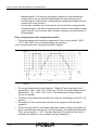
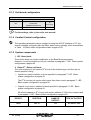
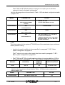
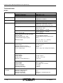
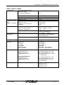
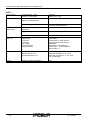
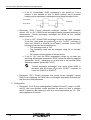
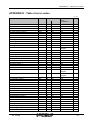
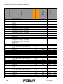
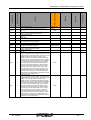
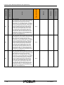
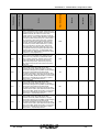
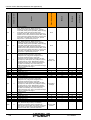
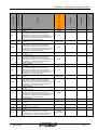
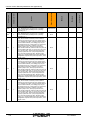
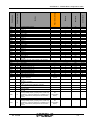
QX6: Set as for Y28. Controls passive cooling.
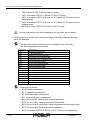
QX21 of module AVS75 n°1: Set as for Q20. CP pump.
QX21 of module AVS75 n°2: Set as for Y5. Opens the C2 mixer valve in
heating mode.
QX22 of module AVS75 n°2: Set as for Y6. Closes th e C2 mixer valve in
heating mode.
QX23 of module AVS75 n°2: Set as for Q6. C2 pump.
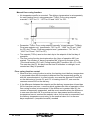
During relay testing, the limits imposed by the controller are not active!
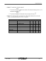
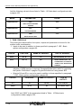
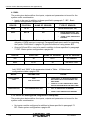
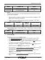
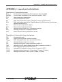
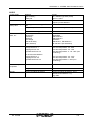
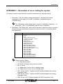
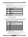
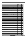
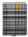
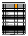
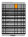
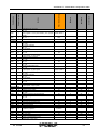
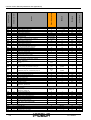
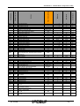
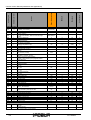
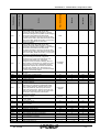
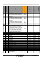
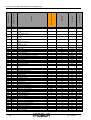
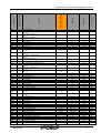
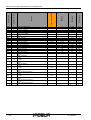
3. “Sensor input test” parameters, selecting an input test setting displays the input
value for validation.
The displayed values of the sensors are updated every 5 seconds.
The value displayed is uncorrected.
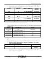
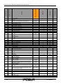
Row number
Operating row
7730
External temperature B9
7732
Flow temperature B1
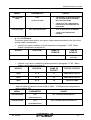
7750
DHW charging temperature B3
7770
Heat pump flow temperature B21
7771
Heat pump return temperature B71
7772
Hot-gas temperature B81
7775
Source flow temperature B91
7777
Sensor temperature BX1
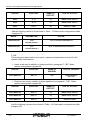
7820
Sensor temperature BX2
7821
Sensor temperature BX3
7823
Sensor temperature BX4
7824
Sensor temperature BX5
7830
Sensor temperature BX21, module 1
7831
Sensor temperature BX22, module 1
7832
Sensor temperature BX21, module 2
7833
Sensor temperature BX22, module 2
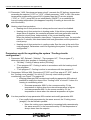
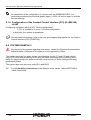
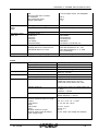
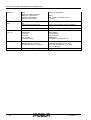
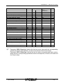
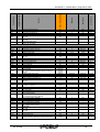
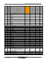
Inputs used by Robur:
• B9: External temperature.
• B1: C1 delivery temperature.
• B3: DHW tank upper temperature.
• B71: Heat pump return temperature.
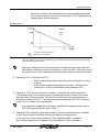
• BX1: Set as for B4. Heating tank upper temperature.
• BX2: Set as for B41. Heating tank lower temperature.
• BX3: Set as for B10. Heat pump delivery temperature after heating tank.
• BX4: Set as for B31. DHW tank lower temperature.
• BX21 of module AVS75 n°2: Set as for B41. C2 deliv ery temperature.
148
Ed. 12/2008