1
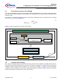
XC800 Family
AP08100
Configuration for Capacitive Touch-Sensing Application
Application Note
V1.0, 2010-06
Microcontrollers
Edition 2010-06
Published by
Infineon Technologies AG
81726 Munich, Germany
© 2010 Infineon Technologies AG
All Rights Reserved.
LEGAL DISCLAIMER
THE INFORMATION GIVEN IN THIS APPLICATION NOTE IS GIVEN AS A HINT FOR THE IMPLEMENTATION
OF THE INFINEON TECHNOLOGIES COMPONENT ONLY AND SHALL NOT BE REGARDED AS ANY
DESCRIPTION OR WARRANTY OF A CERTAIN FUNCTIONALITY, CONDITION OR QUALITY OF THE
INFINEON TECHNOLOGIES COMPONENT. THE RECIPIENT OF THIS APPLICATION NOTE MUST VERIFY
ANY FUNCTION DESCRIBED HEREIN IN THE REAL APPLICATION. INFINEON TECHNOLOGIES HEREBY
DISCLAIMS ANY AND ALL WARRANTIES AND LIABILITIES OF ANY KIND (INCLUDING WITHOUT
LIMITATION WARRANTIES OF NON-INFRINGEMENT OF INTELLECTUAL PROPERTY RIGHTS OF ANY
THIRD PARTY) WITH RESPECT TO ANY AND ALL INFORMATION GIVEN IN THIS APPLICATION NOTE.
Information
For further information on technology, delivery terms and conditions and prices, please contact the nearest
Infineon Technologies Office (www.infineon.com).
Warnings
Due to technical requirements, components may contain dangerous substances. For information on the types in
question, please contact the nearest Infineon Technologies Office.
Infineon Technologies components may be used in life-support devices or systems only with the express written
approval of Infineon Technologies, if a failure of such components can reasonably be expected to cause the failure
of that life-support device or system or to affect the safety or effectiveness of that device or system. Life support
devices or systems are intended to be implanted in the human body or to support and/or maintain and sustain
and/or protect human life. If they fail, it is reasonable to assume that the health of the user or other persons may
be endangered.
AP08100
Configuration for Capacitive Touch-Sensing Application
XC82x/XC83x
Revision History: V1.0 2010-06
Previous Version(s):
Page
Subjects (major changes since last revision)
–
This is the first release …
We Listen to Your Comments
Is there any information in this document that you feel is wrong, unclear or missing? Your feedback will help us to
continuously improve the quality of this document. Please send your proposal (including a reference to this document) to:
[email protected]
Application Note
3
V1.0, 2010-06
AP08100
Configuration for Capacitive Touch-Sensing Application
Table of Contents
Table of Contents
1
1.1
Introduction . . . . . . . . . . . . . . . . . . . . . . . . . . . . . . . . . . . . . . . . . . . . . . . . . . . . . . . . . . . . . . . . . . . . . 5
Overview . . . . . . . . . . . . . . . . . . . . . . . . . . . . . . . . . . . . . . . . . . . . . . . . . . . . . . . . . . . . . . . . . . . . . . . . 5
2
2.1
2.2
2.2.1
2.3
2.4
2.5
Touch-Sense Parameter Setting Workflow . . . . . . . . . . . . . . . . . . . . . . . . . . . . . . . . . . . . . . . . . . . 6
Touch-Sense Counter Clock Setting . . . . . . . . . . . . . . . . . . . . . . . . . . . . . . . . . . . . . . . . . . . . . . . . . . 7
Compare Value Setting . . . . . . . . . . . . . . . . . . . . . . . . . . . . . . . . . . . . . . . . . . . . . . . . . . . . . . . . . . . . . 7
Sensitivity Factor . . . . . . . . . . . . . . . . . . . . . . . . . . . . . . . . . . . . . . . . . . . . . . . . . . . . . . . . . . . . . . . . 9
Accumulation & Low Pass Filter (LPF) Gain Setting . . . . . . . . . . . . . . . . . . . . . . . . . . . . . . . . . . . . . 10
Trip Point Setting . . . . . . . . . . . . . . . . . . . . . . . . . . . . . . . . . . . . . . . . . . . . . . . . . . . . . . . . . . . . . . . . 13
Valid Pad Touch Detection Period Setting . . . . . . . . . . . . . . . . . . . . . . . . . . . . . . . . . . . . . . . . . . . . . 15
3
3.1
3.1.1
3.1.2
3.1.3
3.2
3.2.1
3.2.2
3.3
3.3.1
3.3.2
Calibration Tool (U-SPY) . . . . . . . . . . . . . . . . . . . . . . . . . . . . . . . . . . . . . . . . . . . . . . . . . . . . . . . . .
Compare-Calibration Tool . . . . . . . . . . . . . . . . . . . . . . . . . . . . . . . . . . . . . . . . . . . . . . . . . . . . . . . . . .
Code Generation and Compilation . . . . . . . . . . . . . . . . . . . . . . . . . . . . . . . . . . . . . . . . . . . . . . . . .
Procedure . . . . . . . . . . . . . . . . . . . . . . . . . . . . . . . . . . . . . . . . . . . . . . . . . . . . . . . . . . . . . . . . . . . .
Compare Calibration . . . . . . . . . . . . . . . . . . . . . . . . . . . . . . . . . . . . . . . . . . . . . . . . . . . . . . . . . . . .
Module-Calibration Tool . . . . . . . . . . . . . . . . . . . . . . . . . . . . . . . . . . . . . . . . . . . . . . . . . . . . . . . . . . .
Code Generation and Compilation . . . . . . . . . . . . . . . . . . . . . . . . . . . . . . . . . . . . . . . . . . . . . . . . .
Procedure . . . . . . . . . . . . . . . . . . . . . . . . . . . . . . . . . . . . . . . . . . . . . . . . . . . . . . . . . . . . . . . . . . . .
RomLib-Calibration Tool . . . . . . . . . . . . . . . . . . . . . . . . . . . . . . . . . . . . . . . . . . . . . . . . . . . . . . . . . . .
Code Generation and Compilation . . . . . . . . . . . . . . . . . . . . . . . . . . . . . . . . . . . . . . . . . . . . . . . . .
Procedure . . . . . . . . . . . . . . . . . . . . . . . . . . . . . . . . . . . . . . . . . . . . . . . . . . . . . . . . . . . . . . . . . . . .
4
Summary . . . . . . . . . . . . . . . . . . . . . . . . . . . . . . . . . . . . . . . . . . . . . . . . . . . . . . . . . . . . . . . . . . . . . . 31
Application Note
4
19
21
23
24
25
26
27
27
29
30
30
V1.0, 2010-06
AP08100
Configuration for Capacitive Touch-Sensing Application
Introduction
1
Introduction
This application note is for the XC82x/XC83x family of products and describes the configuration of the main
parameters for touch-sensing applications, as well as introducing various calibration methodologies. For detailed
descriptions of the XC82x/XC83x products, please refer to the XC82x/XC83x User’s Manual.
1.1
Overview
The LED Touch Sense Control Unit (LEDTSCU) provides a time-multiplexed control for matrix LED driving and
touch sensing. The LEDTS ROM Library is integrated into the Microcontroller ROM and consists of the
FINDTOUCHEDPAD and SET_LDLINE_CMP functions. These functions are to be called from Time Slice and/or
Time Frame Interrupt Service Routines. The input parameters need to be set up by the the user before calling
these functions. Figure 1 shows the main hardware and software components the user needs to control/set up for
the touch-sensing (and LED) applications. The parameter setup details will be covered in Chapter 2.
LEDTSCU
Interrupt Control
Functional Control
CLK_PS
prescaler
48MHz
8MHz
Time-Frame
CLKSEL
SHD_CMP
LED Driving
NR_LEDCOL
NR_PADT
Time-Slice
Touch Sensing
SET_LDLINE_CMP
ISR
call ROMLIB
LEDTS ROM Library
FINDTOUCHEDPAD
LEDLINE [7]
LEDLINE
LEDCMP[6]
[7]
LEDLINE[5]
LEDCMP[6]
LEDLINE
LEDCMP[5]
[4]
LEDLINE
LEDCMP[4]
[3]
LEDLINE
LEDCMP[2]
[3]
LEDLINE[1]
LEDCMP [2]
LEDLINE[0]
LEDCMP[1]
LEDCMP[0]
Average0
Average1
mux
Average2
Average3
Average4
Average5
Average6
Average7
Total_TSCTR
LowTrip
subtraction
PadFlag0
PadFlag1
compare
+
Y = X – Subtraction
Subtractionm
m
PadFlag2
PadFlag3
PadFlag4
PadFlag5
PadFlag6
PadFlag7
increment PADT
i= 0
accumulate
AcCnt
LTS_TSVAL
Σ
i= 1
Figure 1
low pass filter
Y’ = K/T*Y + X – 1/T*Y
Divisor
n n
K = T = 2Divisor
Overview of the Main LED and Touch-Sense Configurable Components
The LEDTS ROM Library FINDTOUCHEDPAD function contains a noise rejection feature. The Average value
calculation uses a moving average filter for noise measurement which makes the touch detection handling robust.
Calibration is not required during application run-time, as the LEDTS ROM Library allows the system to adapt to
variations caused by the environmental changes, for example, temperature, humidity, dirt, etc. There are several
application-specific configuration options for the LEDTS ROM Library input parameters (AccumulatorCounter,
Divisor n, Subtraction m (Trip Point setting), Compare value). Calibration tools (U-SPY) are provided to assist in
parameter configuration (refer to Chapter 3).
Application Note
5
V1.0, 2010-06
AP08100
Configuration for Capacitive Touch-Sensing Application
Touch-Sense Parameter Setting Workflow
2
Touch-Sense Parameter Setting Workflow
There are 5 major steps to configure the touch-sense parameter settings:
1.
2.
3.
4.
5.
Touch-Sense Counter Clock Setting
Compare Value Setting
Accumulation & Low Pass Filter (LPF) Gain Setting
Trip Point Setting
Valid Pad Touch Detection Period Setting
Figure 2 shows the flow of touch-sense parameter setting. Each parameter setting will be further explained in
detail in following sections.
Touch Sense
Parameter Setting
Determine time slice duration as per application
needs.
TS-Counter clock
setting
1
Calculate CLK_PS with appropriate CLKSEL.
Determine “LOWLIMIT” and “HIGHLIMIT”
. Get
calibrated COMPAREx values and corresponding
TSVALx values
Compare value
setting
2
Get minimum TS-counter value change without
any gain/filter applied (∆TSVALx)
Determine the Total Gain required based on Min.
counter value change needed for detection
(∆TSVAL_RQD).
3
Accumulation & LPF
Gain setting
Call “LEDTS ROMLIB” functions with different
combinations of AccumulatorCounter & Divisor n
Observe changes in AVERAGEx value during
touched and untouched (idle)
Compare sensitivity performance of different
combinations of AccumulatorCounter & Divisor n
Figure 2
4
Trip point setting
Calculate Subtraction m (OFFSET) from
∆TSVAL_AVG (recommended range: 40~80%)
5
Valid & Long pad
touch setting
Define valid & long pad touch detection period as
per application needs.
Overview Flowchart of Touch-Sense Parameter Setting
Application Note
6
V1.0, 2010-06
AP08100
Configuration for Capacitive Touch-Sensing Application
Touch-Sense Parameter Setting Workflow
2.1
Touch-Sense Counter Clock Setting
The user must first determine the time slice duration (TSD) for the application. The TSD is the maximum length of
time that a single pad is enabled for touch-sensing. The TSD defines the interval of the time slice/time frame
interrupt events.
Once the time slice duration is fixed, the clock pre-scale factor (PREscaler) can be calculated from the selected
input clock fCLK, as shown in Equation (1).
(1)
TSD × f CLK
PREscaler = ----------------------------8
2
Figure 3 shows the example of TS-counter clock setting.
Example: Number of Touch pads = 3; Number of LED columns = 2; Covering plate = 2mm Glass
TSD = 1.5 ms
fCLK = 8MHz
+
PREscaler = (TSD * fCLK)/(2^8)
(1 ≤ PREscaler ≤ 63)
fCLK = 48MHz
PREscaler = 46
(fCLK = 8MHz)
LTS_GLOBCTL0.CLK_PS = 101110B
LTS_GLOBCTL1.CLKSEL = 1
User-defined Parameters
Registers to be configured
Figure 3
Touch-Sense Counter Clock Setting (Example)
2.2
Compare Value Setting
The compare value determines the active duration during which the pad oscillation is enabled within the touchsense time slice duration (TSD) where the TS-counter is counting. The bigger the compare value, the smaller the
oscillation window, therefore fewer oscillations are counted. For example, a compare value 0x00 enables
oscillation for the full duration of the time slice, whereas 0xFF disables oscillation. Figure 4 shows the oscillation
window with respect to compare value in a time slice duration.
Application Note
7
V1.0, 2010-06
AP08100
Configuration for Capacitive Touch-Sensing Application
Touch-Sense Parameter Setting Workflow
LTS_COMPARE = 0x00
Oscillation Window
…
…
Time Slice Duration
LTS_COMPARE = 0x7F
Oscillation Window
…
Time Slice Duration
Figure 4
Oscillation Window (with respect to Compare value)
In order to maximize the resolution, compare value should be selected to maximize the oscillation count without
overflowing the TS-counter (LTS_TSCTL.TSCTROVF=0). Note that the compare value should be large enough
to ensure there is sufficient time to read out the oscillation count data before it is cleared by the LEDTSCU when
the next pad turn is started. Figure 5 shows the example of compare value setting. The LOWLIMIT and
HIGHLIMIT are the user defined range of TS-counter within the enabled oscillation window.
Application Note
8
V1.0, 2010-06
AP08100
Configuration for Capacitive Touch-Sensing Application
Touch-Sense Parameter Setting Workflow
Example: Number of Touch pads = 3; Number of LED columns = 2; Covering plate = 2mm Glass
LTS_GLOBCTL0.CLK_PS = 101110B
LTS_GLOBCTL1.CLKSEL = 1
COMPARE (PADT0) = 0xD6
+
Compare value calibration
COMPARE (PADT1) = 0xCA
COMPARE (PADT2) = 0xC5
LOWLIMIT = 0xB2 (default)
HIGHLIMIT = 0xCC (default)
LTS_COMPARE = 0x7F (COL0)
CMP_OPTION = 0xFF
COMPARE (COL0) = 0x7F
COMPARE (COL1) = 0x7F
COMPARE (PADT0) = 0xD6
COMPARE (PADT1) = 0xCA
COMPARE (PADT2) = 0xC5
User-defined Parameters
Registers to be configured
Figure 5
Compare Value Setting (Example)
2.2.1
Sensitivity Factor
ROMLIB Parameters to be set
The pad oscillation frequency affects the sensitivity of the touch pad and the compare value selection. Device
specific factors, for example, external pull up, presence of LEDs, etc., affect the oscillation frequency. Therefore
the user should pay attention to the external pull-up resistor selection and the LED layout, in order to balance the
sensitivity of the pad and the accuracy of the detection.
The pad oscillation frequency increases by using a smaller external pull-up (connected to COLA pin). This results
in better sensitivity although it increases the crosstalk between adjacent pads.
LED driving and touch pad sensing is time-multiplexed on a single pin. Therefore, the presence of LEDs modifies
the equivalent capacitance for a touch pad. The recommendation is to reduce the number of LEDs connected to
the touch pads. If it is necessary, LEDs should be located near to the touch pads, to reduce the additional parasitic
capacitance introduced by the traces.
Application Note
9
V1.0, 2010-06
AP08100
Configuration for Capacitive Touch-Sensing Application
Touch-Sense Parameter Setting Workflow
2.3
Accumulation & Low Pass Filter (LPF) Gain Setting
A touch on the pad will decrease the oscillation count on the TS-counter and the differences of the TS-counter is
defined as ∆TSVAL. ∆TSVAL can be obtained by using Module-Calibration Tool.
(2)
∆TSVAL = LTS_TSVAL(idle) – LTS_TSVAL(touched)
An amplification of the ∆TSVAL is achieved by applying multi-sampling and a low pass filter to increase the
resolution and accuracy of touch pad detection. This helps to smooth out low and high frequency noise.
The multi-sampling (TOTAL_TSCTRL/H) accumulates the pad oscillation count by a configurable number
(=AccumulatorCounter) of times shown in Equation (3). A low pass filter is embedded in the Average value
calculation shown in Equation (4). The Average value will be updated all the time by the FINDTOUCHEDPAD
function, unless a touch on a pad is detected (PADFLAG>1).
(3)
AccumulatorCounter
∑
TOTAL_TSCTRL/H(x) =
LTS_TSVAL(i)
i=1
where AccumulatorCounter is a user-defined input parameter to the FINDTOUCHEDPAD function and ranges
from 1 to 255.
(4)
AVERAGEL/H(x-1)AVERAGEL/H(x) = AVERAGEL/H(x-1) + TOTAL_TSCTRL/H(x) – ------------------------------------------------Divisor n
2
where the Divisor n is user-defined input parameter for FINDTOUCHEDPAD function, ranges from 1 to 8.
Once ∆TSVAL is known, with the user-defined minimum counter value change required for the detection
(∆TSVAL_RQD), the minimum Total Gain required can be calculated as:
(5)
Total_Gain = ( ∆TSVAL_RQD ) ⁄ ( ∆TSVAL )
The Total_Gain is the combination of the AccumulatorCounter and the LPF_Gain:
(6)
Total_Gain = AccumulatorCounter × LPF_Gain
where LPF_Gain is 2Divisor n
Several possible combinations of AccumulatorCounter and Divisor n can achieve the same Total_Gain
requirement. However, different combinations result in different key response times. When the Divisor n becomes
larger, the response time becomes longer. Therefore the user needs to determine a suitable combination, based
on the application as well as the sensitivity performance. The user also needs to take care to ensure the
Total_Gain does not exceed the maximum of 256.
Application Note
10
V1.0, 2010-06
AP08100
Configuration for Capacitive Touch-Sensing Application
Touch-Sense Parameter Setting Workflow
The RomLib-Calibration Tool is provided to assist the user to evaluate the sensitivity and performance of
different configuration options. During calibration, the PADFLAG needs to be cleared after calling the
FINDTOUCHEDPAD function, so that the Average value will be updated all the time, even though a touch on a
pad is detected (PADFLAG>1).
Figure 6 shows the example of AccumulatorCounter and Divisor n settings.
Application Note
11
V1.0, 2010-06
Figure 6
Application Note
COMPARE (PADT2) = 0xC5
COMPARE (PADT1) = 0xCA
COMPARE (PADT0) = 0xD6
LTS_GLOBCTL1.CLKSEL = 1
LTS_GLOBCTL0.CLK_PS = 101110B
Module
calibration
12
User-defined Parameters
∆TSVAL_RQD = 20
+
∆TSVAL (PADT2) = 4
∆TSVAL (PADT1) = 8
∆TSVAL (PADT0) = 8
Divisor n = 0x01
AccumulatorCounter = 0x03
Divisor n = 0x00
AccumulatorCounter = 0x06
Divisor n = 0x01
AccumulatorCounter = 0x03
Total_Gain = 6
ROMLIB Parameters to be set
function.)
(PADFLAG is
cleared after calling
FINDTOUCHEDPAD
ROMLIB
calibration
Example: Number of Touch pads = 3; Number of LED columns = 2; Covering plate = 2mm Glass
AP08100
Configuration for Capacitive Touch-Sensing Application
Touch-Sense Parameter Setting Workflow
AccumulatorCounter & Divisor n Settings (Example)
V1.0, 2010-06
AP08100
Configuration for Capacitive Touch-Sensing Application
Touch-Sense Parameter Setting Workflow
2.4
Trip Point Setting
A touch on the pad will decrease the TS-counter, thus resulting in differences in the Average value. ∆TSVAL_AVG
is the differences of the Average value in idle state and in touched state, as shown in Equation (7). The Trip point
(LOWTRIPL/H) is defined as the level where a pad touch is detected. It is obtained by subtracting a value
(Subtraction m) from the Average value (idle), as shown in Equation (8). The user is able to get the Average value
at the idle and touched state as the “threshold” from the RomLib-Calibration Tool.
(7)
∆TSVAL_AVG = AVERAGEL/H(idle) – AVERAGEL/H(touched)
(8)
LOWTRIPL/H(x) = AVERAGEL/H(x) – SUBTRACTION m
where the Subtraction m is a user-defined input parameter to the FINDTOUCHEDPAD function.
Figure 7 and Figure 8 illustrate the Subtraction m and Trip Point for touch-sense detection. The Subtraction m
value is recommended to be 40%-80% of the ∆TSVAL_AVG. With a smaller Subtraction m value, the pad
becomes more sensitive to the detection and noise. The user must select a suitable Subtraction m value to
balance the sensitivity and accuracy of the detection.
AVERAGE (idle/untouched)
40%*∆TSVAL_AVG
80%*∆TSVAL_AVG
Min. SUBTRACTION m
Max. SUBTRACTION m
∆TSVAL_AVG
AVERAGE (touched)
40%*∆TSVAL_AVG ≤ SUBTRACTION m ≤ 80%*∆TSVAL_AVG (recommended)
Figure 7
Illustration of Subtraction m
AVERAGE (idle/untouched)
SUBTRACTION m
LOWTRIP
AVERAGE (touched)
Figure 8
Illustration of Trip Point
Application Note
13
V1.0, 2010-06
AP08100
Configuration for Capacitive Touch-Sensing Application
Touch-Sense Parameter Setting Workflow
Figure 9 shows a zoomed-in view of the Trip Point with respect to the Average value due to low pass filter effect.
AVERAGE (idle/untouched)
LOWTRIP
SUBTRACTION m
AVERAGE (touched)
Figure 9
Enlarged View of Trip Point
Figure 10 shows the example of Trip Point setting.
Example: Number of Touch pads = 3; Number of LED columns = 2; Covering plate = 2mm Glass
LTS_GLOBCTL0.CLK_PS = 101110B
LTS_GLOBCTL1.CLKSEL = 1
LTS_COMPARE = 0x7F (COL0)
AccumulatorCounter = 0x03
Divisor n = 0x01
ShortCount = 0x01
Subtraction m = 0x00
Common Subtraction m = 0xB0
CMP_OPTION = 0xFF
ROMLIB
calibration
∆TSVAL_AVE (PADT0) = 45
18 ≤ Subtraction m (PADT0) ≤ 36
(PADFLAG is
cleared after calling
FINDTOUCHEDPAD
function.)
∆TSVAL_AVE (PADT1) = 56
23 ≤ Subtraction m (PADT1) ≤ 44
∆TSVAL_AVE (PADT2) = 52
21 ≤ Subtraction m (PADT2) ≤ 41
COMPARE (COL0) = 0x7F
COMPARE (COL1) = 0x7F
COMPARE (PADT0) = 0xD6
COMPARE (PADT1) = 0xCA
COMPARE (PADT2) = 0xC5
Subtraction m = 0x50
Subtraction m (PADT0) = 0x12
Subtraction m (PADT1) = 0x17
Subtraction m (PADT2) = 0x15
ROMLIB Parameters to be set
Figure 10
Trip Point Setting (Example)
Application Note
14
V1.0, 2010-06
AP08100
Configuration for Capacitive Touch-Sensing Application
Touch-Sense Parameter Setting Workflow
2.5
Valid Pad Touch Detection Period Setting
The pad detection period depends on many parameters such as the number of pad turns and LED columns
enabled, accumulation of SFR LTS_TSVAL, etc. For a fixed/defined “All enabled pads accumulated count period”
(AEPACP), the ShortCount determines the minimum “valid pad detection period” (VPDP). The minimum and
maximum valid pad detection period can be calculated as shown in Equation (10) and Equation (11).
(9)
AEPACP = TFD × ( Number of Touch-sense inputs TSIN[x] ) × ( AccumulatorCounter + 1 )
where TSD is Time Frame Duration = (((PREscaler x 256)/fCLK) x (Number of Time Slice(s))), and
AccumulatorCounter is the user-defined input for the FINDTOUCHEDPAD function.
(10)
Minimum Valid Pad Detection Period (VPDP) = ( 0xFF – ShortCount + 1 ) × AEPACP
(11)
Maximum Valid Pad Detection Period (VPDP) = 0xFF × AEPACP
The user is able to decrease the maximum valid pad detection period by introducing an ErrorCount, as shown in
Equation (12).
(12)
Maximum Valid Pad Detection Period (VPDP) = ( 0xFF – ErrorCount + 1 ) × AEPACP
The user can increase the valid pad detection period by:
•
•
•
enabling dummy LED columns (without assigning/setting the LED column pins)
selecting 8 MHz input clock (CLKSEL)
selecting bigger PREscale factor (CLK_PS)
The user can decrease the valid pad detection period by:
•
•
selecting 48 MHz input clock (CLKSEL)
selecting smaller PREscale factor (CLK_PS)
A pad touch is considered valid only when the pad touched period is between the minimum and maximum valid
pad detection period, as shown in Figure 11. In invalid cases, a pad touch is considered “too short” (typically
ignore) or “too long” (typically error), as shown in Figure 12 and Figure 13.
Application Note
15
V1.0, 2010-06
AP08100
Configuration for Capacitive Touch-Sensing Application
Touch-Sense Parameter Setting Workflow
TOTAL_TSCTR
AVERAGE (idle/untouched)
LOWTRIP
AVERAGE (touched)
FFH FEH
PDC
F7H F6H
...
A0H
...
ERRORCOUNT = 0xA0
SHORTCOUNT = 0xF7
AEPACP
First PadFlag being set,
PDC initialized to 0xFF
PadFlag = 0
Figure 11
Last PadFlag being cleared,
PDC cleared to 0x00
PadTouchPeriod
PadFlag > 0
PadFlag = 0
Valid Pad Touch (PadResult Flag)
TOTAL_TSCTR
AVERAGE (idle/untouched)
LOWTRIP
AVERAGE (touched)
FFH FEH
PDC
F7H F6H
...
A0H
...
ERRORCOUNT = 0xA0
SHORTCOUNT = 0xF7
AEPACP
First PadFlag being set,
PDC initialized to 0xFF
PadFlag = 0
Figure 12
Last PadFlag being cleared,
PDC cleared to 0x00
PadTouchPeriod
PadFlag > 0
PadFlag = 0
Invalid Pad Touch due to “Too Short” Touch Duration (Ignore)
Application Note
16
V1.0, 2010-06
AP08100
Configuration for Capacitive Touch-Sensing Application
Touch-Sense Parameter Setting Workflow
TOTAL_TSCTR
AVERAGE (idle/untouched)
LOWTRIP
AVERAGE (touched)
FFH FEH
PDC
F7H F6H
...
A0H
...
ERRORCOUNT = 0xA0
SHORTCOUNT = 0xF7
AEPACP
First PadFlag being set,
PDC initialized to 0xFF
PadTouchPeriod
PadFlag = 0
Figure 13
PadFlag > 0
Last PadFlag being cleared,
PDC cleared to 0x00
PadFlag = 0
Long Pad Touch (PadError Flag)
Figure 14 shows the example of ShortCount and ErrorCount settings.
Application Note
17
V1.0, 2010-06
AP08100
Configuration for Capacitive Touch-Sensing Application
Touch-Sense Parameter Setting Workflow
Example: Number of Touch pads = 3; Number of LED columns = 2; Covering plate = 2mm Glass
PREscaler = 0x2E
fCLK = 8MHz
NR_PADT = 2
AccumulatorCounter = 0x03
Min./Max. VPDP = (0xFF – ShortCount/
ErrorCount+1)*((No. of Columns+1)*(No. of Pad turns+1)
*(AccumulatorCounter+1)*((2^8)*PREscaler)/fCLK)
+
ShortCount = 0xF7
ErrorCount = 0xA0
Min. VPDP = 400ms
Max. VPDP = 5s
NR_LEDCOL = 1
LTS_LDTSCTL. NR_LEDCOL = 001B
ShortCount = 0xF7
ErrorCount = 0xA0
User-defined Parameters
Figure 14
Registers to be configured
ROMLIB Parameters to be set
ShortCount & ErrorCount Settings (Example)
Application Note
18
V1.0, 2010-06
AP08100
Configuration for Capacitive Touch-Sensing Application
Calibration Tool (U-SPY)
3
Calibration Tool (U-SPY)
U-SPY is part of the free tool DAvE-Bench. It is a flexible and easy-to-use tool to set up and observe parameters
via a UART to USB interface in real-time. Different GUI interfaces/elements can be set-up via different Initialization
files. The touch-sense calibration tool contains a hex file (including set up for communication and LEDTSCU
module) and U-SPY initialization (ini) file.
There are three aspects of calibration available for the user:
•
•
•
Compare-Calibration Tool (To calibrate SFR LTS_COMPARE values for all enabled pads)
Module-Calibration Tool (To fine-tune SFR LTS_COMPARE values for all enabled pads)
RomLib-Calibration Tool (To observe the sensitivity performance of all enabled pads)
The calibration set-up is shown in Figure 15.
Program & Calibration Tools installed.
Program Tool : KEIL / SDCC / FLOAD
Calibration Tool: U-SPY with ini file
Program hex file into the Flash
so that the device is able to
communicate with U-SPY
through full-duplex UART
Serial/USB
Connector
Connect to PC COM
(Virtual) port via
Serial/USB cable
Target Board
PC
Figure 15
MCU
Calibration Set-Up
To use the calibration tool, the user needs to have the hex and ini files. The main procedure for using the
calibration tool (from code generation to using U-SPY) is shown below:
•
•
•
•
•
•
•
Set up modules in DAvE and generate code
Compile code to obtain the hex file
Download hex file to device
Execute Flash
Open U-SPY tool on PC
Load initialization (ini) file in U-SPY
Use calibration tool as provided
Each calibration tool is described in detail in respective sections. Table 1 shows a list of the initialization files for
different calibration tools. Figure 16 shows an overview of using the calibration tools to calibrate the parameters
for a touch-sensing application.
Application Note
19
V1.0, 2010-06
AP08100
Configuration for Capacitive Touch-Sensing Application
Calibration Tool (U-SPY)
Table 1
Listing of Initialization Files for Calibration Tools
Calibration Aspect
Folder / Project / Hex Name
Initialization File
Compare-Calibration Tool
USpy_CompareCalibration
uspy_CompareCalibration_Compare.ini
uspy_CompareCalibration_TSVAL.ini
uspy_CompareCalibration_Result.ini
Module-Calibration Tool
USpy_ModuleCalibration
uspy_ModuleCalibration_PadGrp1.ini
uspy_ModuleCalibration_PadGrp2.ini
RomLib-Calibration Tool
USpy_RomlibCalibration
uspy_RomLibCalibration.ini
Touch Sense
Parameter Setting
TS-Counter clock
setting
1
Compare Value
setting
2
Compare-Calibration Tool
Get calibrated COMPAREx & respective
TSVALx based on user’s required range
Module-Calibration Tool
For fine-tuning or selecting small
COMPARE value (< 0x10)
Module-Calibration Tool
- Get ∆TSVALx during touched and
untouched (Idle)
3
Figure 16
Accumulation & LPF
Gain setting
4
Trip point setting
5
Valid & Long pad
touch setting
RomLib-Calibration Tool
- Observe AVERAGEx waveform during
touched and untouched (Idle)
- Compare the sensitivity performance of
different combinations of
AccumulatorCounter & Divisor n
RomLib-Calibration Tool
- Measure AVERAGEx value during
touched and untouched (Idle) to get
∆TSVAL_AVG
- Calculate Subtraction m from
∆TSVAL_AVG
Overview Flow of Using Calibration Tools
Application Note
20
V1.0, 2010-06
AP08100
Configuration for Capacitive Touch-Sensing Application
Calibration Tool (U-SPY)
3.1
Compare-Calibration Tool
The Compare-Calibration Tool is used to get the calibrated SFR LTS_COMPARE values for all enabled pads, with
the corresponding SFR LTS_TSVAL values. Pass or fail flags are given to determine the calibration status.
There are three ini files for the Compare-Calibration Tool:
•
•
•
uspy_CompareCalibration_Compare.ini
uspy_CompareCalibration_TSVAL.ini
uspy_CompareCalibration_Result.ini
Different ini files means different GUI interfaces, and each ini file has a different usage.
uspy_CompareCalibration_Compare.ini is used to calibrate the compare values (SFR LTS_COMPARE).
uspy_CompareCalibration_TSVAL.ini provides the corresponding TS-counter values with respect to the calibrated
compare values. uspy_CompareCalibration_Result.ini is used to analyze the calibration results. Calibration for a
pad is successful when its fail flag is not set i.e., not highlighted in black. If there is no fail flag set in using
uspy_CompareCalibration_Compare.ini,
it
is
not
necessary
to
analyze
the
data
using
uspy_CompareCalibration_TSVAL.ini and uspy_CompareCalibration_Result.ini.
The user should disregard the respective SFR LTS_COMPARE and LTS_TSVAL values when a fail flag is set, as
indicated in the GUI interface. To analyze why the calibration process fails, and how to change the pad oscillation
frequency and the expected TS-counter value range, the uspy_CompareCalibration_Result.ini can be used. The
result parameters are described in Table 3.
The GUI interfaces are shown in Figure 17 and Figure 18 respectively. Table 2 shows the corresponding display
fields with respect to SFR fields and functions. The code generation and compilation is described in Section 3.1.1.
The procedure for using the Compare-Calibration Tool is described in Section 3.1.2.
Figure 17
Compare-Calibration Tool (Showing LTS_COMPARE)
Application Note
21
V1.0, 2010-06
AP08100
Configuration for Capacitive Touch-Sensing Application
Calibration Tool (U-SPY)
Figure 18
Compare-Calibration Tool (Showing LTS_TSVAL and Result)
Table 2 shows the corresponding display fields with respect to SFR fields and functions.
Table 2
Display of the Compare-Calibration Tool
Display Field
SFR Field
Input/Output Description
LOWLIMIT
-
Input/Output
The low limit for LTS_TSVAL value (Default B2H)
HIGHLIMIT
-
Input/Output
The high limit for LTS_TSVAL value (Default CCH)
CLK_PS
LTS_GLOBCTL0.CLK_PS
Input/Output
To adjust pad oscillation frequency
CLKSEL
LTS_GLOBCTL1.CLKSEL
Input/Output
To adjust pad oscillation frequency
Compare (x)
LTS_COMPARE
Output
To obtain the calibrated compare values
TSVAL (x)
LTS_TSVAL
Output
To obtain the corresponding TS-counter values
Result (x)
-
Output
To obtain the corresponding ok/error results of
calibration process, see Table 3
TSFINISH
-
Output
0xAA indicates completion of calibration process
Fail (x)
-
Output
To indicate pass or fail status of calibration process
(Fail status will be highlighted in black)
Application Note
22
V1.0, 2010-06
AP08100
Configuration for Capacitive Touch-Sensing Application
Calibration Tool (U-SPY)
TSRESULT parameters indicate the output ok/error results of Compare-Calibration Tool. There are 3 types of
error results. Their respective description, value and next-actions are defined in Table 3.
Table 3
TSRESULT Parameters
Parameter
Value
Description
Next Action
PASS / OK
55H
COMPARE parameter has been
calibrated successfully
N.A.
ERROR1
FFH
Calibration is not successful.
Touch pad oscillation frequency is too high.
Overflow occurs and LTS_COMPARE Do the following and re-calibrate touch pad
is 0xFE
• Reduce time slice duration1) or
• Reduce touch pad oscillation frequency2)
ERROR2
EEH
Calibration is not successful.
LTS_TSVAL> HIGHLIMIT and
LTS_COMPARE is 0xFE
Touch pad oscillation frequency is too high.
Do the following and re-calibrate touch pad
• Reduce time slice duration1) or
• Reduce touch pad oscillation frequency2) or
• Increase HIGHLIMIT value
ERROR3
DDH
Calibration is not successful.
LTS_TSVAL< LOWLIMIT and
LTS_COMPARE is 0x10
Touch pad oscillation frequency is too low.
Do the following and re-calibrate touch pad
• Increase time slice duration3) or
• Increase touch pad oscillation frequency2) or
• Reduce LOWLIMIT value
1) Reduce the PREscaler (CLK_PS) or increase the input clock (fCLK)
2) Refer to Section 2.2.1
3) Increase the PREscaler (CLK_PS) or decrease the input clock (fCLK)
3.1.1
Code Generation and Compilation
The free tools DAvE and DAvE-Bench are used to generate and compile code for calibration. The project files are
found in their respective folders. The DAvE project includes the set up for U-SPY communication and the
LEDTSCU module. The user can modify the project files provided to perform the calibration process for their
application. However the U-SPY set-up must not be modified in order to use the calibration tool.
The main configurations that can be modified by the user are shown in Table 4.
Application Note
23
V1.0, 2010-06
AP08100
Configuration for Capacitive Touch-Sensing Application
Calibration Tool (U-SPY)
Table 4
Type
DAvE
GUI
Main Configurations for Compare-Calibration Tool
Module
Tab
LEDTSCU
Pin Control Operating Mode
General
Control Block /
Function
Description
Enable Touch-sense or LED & Touch-sense
Touch Sense Pins
To select the touch-sense pins
LED Column Enable
To define number of columns
LED Line Pins
To select the LED line pins
LED Column Pins
To select the LED column pins
LED/TS Counter Clock To define time slice duration
COMPARE
To define initial compare value
COLLEV
To select LED column active level
H/W Control Pad Turn To define the number of pad turn(s)
Enable
UART
TSOEXT
To define touch-sense output low level extension
UART
Pin Configuration
To define transmit and receive pins
BRG
BRG Settings
To define the baud rate used by U-SPY
SHINT_viXINTR11Isr
or
SHINT_viXINTR13Isr
To define SFR LTS_LDLINE for LED and TS
(Search for “User-defined-LDLINE”)
DAvE
File
Shared_int.C -
3.1.2
Procedure
Procedure for using Compare-Calibration Tool:
1. Download uspy_CompareCalibration.hex to Flash
2. Execute Flash
3. Open U-SPY
4. Click “File” -> “Open Setting” to select ini file (uspy_CompareCalibration_Compare.ini)
5. Enter the COM port number, adjust the baud rate and connect
6. Click the “Get” button to get current register settings
7. Click the “Auto-Calibrate” button to start Compare-Calibration process.
8. Wait till “TSFINISH=0xAA” (indicating completion of Compare-Calibration process)
9. Click the “Get” button to obtain calibration results
10. Click “Stop” button and then click the “Get” button to clear calibration results
11. Change any input settings and click the “Set” button to confirm changes
12. Repeat Step 7-9 to restart Compare-Calibration process
To continue observing other results, the procedure is:
13. Click the “Stop” button and then click the “Get” button to clear calibration results
14. Disconnect COM port
15. Click “File” -> “Open Setting” to select ini file (uspy_CompareCalibration_LTSVAL.ini) or
(uspy_CompareCalibration_Result.ini)
16. Repeat Step 5 to 12
Application Note
24
V1.0, 2010-06
AP08100
Configuration for Capacitive Touch-Sensing Application
Calibration Tool (U-SPY)
3.1.3
Compare Calibration
The Compare-Calibration Tool utilizes a software-calibration function (LTS_vSWCalibration() in LTS.C) running
on the microcontroller to assist the user in finding suitable compare values (LTS_COMPARE). In this function, the
TS-counter value (LTS_TSVAL) is kept within a user-defined low and high limit range. The low limit (LOWLIMIT)
and high limit (HIGHLIMIT) values, if not defined by the user, are 70% (0xB2) and 80% (0xCC) of full count 255
respectively. The flow chart overview of the software-calibration function is shown in Figure 19.
If it is necessary to choose compare values lower than the minimum compare value (0x10) defined in the softwarecalibration function, the Module-Calibration Tool can be used instead.
Start
LTS_vSWCalibration()
TSCTL .
TSCTROVF = 1?
Decrement
LTS_COMPARE
n
y
LTS_COMPARE =
0xFE?
y
LTS_TSVAL >
HIGHLIMIT?
n
n
y
Increment
LTS_COMPARE
Output Error
n
LTS_TSVAL <
LOWLIMIT?
y
LTS_COMPARE =
0x10?
n
y
Output Results
Output Error
Exit
Figure 19
Overview Flow Chart of LTS_vSWCalibration()
Application Note
25
V1.0, 2010-06
AP08100
Configuration for Capacitive Touch-Sensing Application
Calibration Tool (U-SPY)
3.2
Module-Calibration Tool
The Module-Calibration Tool is used to adjust pad oscillation window and frequency via SFR settings (see
Table 5) to fine-tune the compare value (SFR LTS_COMPARE). This tool is also used to observe the change in
the TS-counter value (SFR LTS_TSVAL) when a pad is touched with respect to untouched (idle).
There are two ini files for the Module-Calibration Tool:
•
•
uspy_ModuleCalibration_PadGrp1.ini
uspy_ModuleCalibration_PadGrp2.ini
Different ini files mean different GUI interfaces. Both ini files have the same usage, but are used for different pad
input pins TSIN[x]. uspy_ModuleCalibration_PadGrp1.ini is used for TSIN0 (pad0), TSIN1 (pad1), TSIN2 (pad2)
and TSIN3 (pad3), while uspy_ModuleCalibration_PadGrp2.ini is used for TSIN4 (pad4), TSIN5 (pad5), TSIN6
(pad6) and TSIN7 (pad7). The GUI interfaces are shown in Figure 20 while Table 5 shows the corresponding
display fields with respect to the SFR fields and functions. The code generation and compilation is described in
Section 3.2.1. The procedure for using the Compare-Calibration Tool is described in Section 3.2.2.
Figure 20
Module-Calibration Tool
Table 5
Display of the Module-Calibration Tool
Display Field
SFR Field
Input/Output
Description
CLK_PS
LTS_GLOBCTL0.CLK_PS
Input/Output
To adjust pad oscillation frequency
CLKSEL
LTS_GLOBCTL1.CLKSEL
Input/Output
To adjust pad oscillation frequency
COMPARE
LTS_COMPARE
Input/Output
To adjust pad oscillation window1)
TSOEXT
LTS_LDTSCTL.TSOEXT
Input/Output
To adjust pad oscillation frequency
Application Note
26
V1.0, 2010-06
AP08100
Configuration for Capacitive Touch-Sensing Application
Calibration Tool (U-SPY)
Table 5
Display of the Module-Calibration Tool (cont’d)
Display Field
SFR Field
Input/Output
Description
NR_PADT
LTS_LDTSCTL.NR_PADT
Input/Output
This defines the number of pad turns enabled
PADT
LTS_TSCTL.PADT
Input/Output
To select the pad turn number2)
PADTSW
LTS_TSCTL.PADTSW
Input/Output
To enable/disable software control pad turn
TS SAT
LTS_TSCTL.TSCTRSAT
Input/Output
To enable/disable saturation of TS-counter
TSVAL (padx)
LTS_TSVAL
Output
To obtain the corresponding TS-counter values
1) When PADTSW=0, COMPARE value is applicable for all pad turns. When PADTSW=1, COMPARE value is applicable for
the selected pad turn (indicated in PADT display field)
2) To select the pad turn number, the user must enable the software control pad turn (PADTSW=1).
3.2.1
Code Generation and Compilation
The free tools DAvE and DAvE-Bench are used to generate and compile code for calibration. The project files are
found in their respective folders. The DAvE project includes the set up for U-SPY communication and the
LEDTSCU module. The user can modify the project files provided to perform the calibration process for their
application. However the U-SPY set-up must not be modified in order to use the calibration tool.
The main configurations that can be modified by the user are shown in Table 6.
Table 6
Type
DAvE
GUI
Configurations for Module-Calibration Tool
Module
Tab
LEDTSCU
Pin Control Operating Mode
General
UART
UART
BRG
DAvE
File
Shared_int.C -
3.2.2
Procedure
Control Block /
Function
Description
Enable Touch-sense or LED & Touch-sense
Touch Sense Pins
To select the touch-sense pins
LED Column Enable
To define number of columns
LED Line Pins
To select the LED line pins
LED Column Pins
To select the LED column pins
LED/TS Counter Clock To define time slice duration
COMPARE
To define initial compare value
COLLEV
To select LED column active level
H/W Control Pad Turn
Enable
To define the number of pad turn(s)
TSOEXT
To define touch-sense output low level extension
Pin Configuration
To define transmit and receive pins
BRG Settings
To define the baud rate used by U-SPY
SHINT_viXINTR11Isr
or
SHINT_viXINTR13Isr
To define SFR LTS_LDLINE for LED and TS
(Search for “User-defined-LDLINE”)
Procedure for using Module-Calibration Tool:
1.
2.
3.
4.
Download uspy_ModuleCalibration.hex to Flash
Execute Flash
Open U-SPY
Click “File” -> “Open Setting” to select ini file (uspy_ModuleCalibration_PadGrp1.ini) for pad0~3
Application Note
27
V1.0, 2010-06
AP08100
Configuration for Capacitive Touch-Sensing Application
Calibration Tool (U-SPY)
5.
6.
7.
8.
Enter the COM port number, adjust the baud rate and connect
Click the “Get” button to get register settings
Click the “Calibrate” button to start Module-calibration process. Observe TSVAL(padx) values
To change any of the register settings (pad oscillation window or frequency), modify respective field(s), and
click the “Set” button to program new values
9. Repeat Step 7 to restart Module-calibration process
10. Touch the pad and observe the changes in corresponding TSVAL(padx) values
To continue observing other pad results, the procedure is:
11. Write “0” to PADT and PADTSW fields, followed by clicking the “Set” button
12. Click the “Stop” button to clear TSVAL(padx) values
13. Disconnect COM port
14. Click “File” -> “Open Setting” to select ini file (uspy_ModuleCalibration_PadGrp2.ini)
15. Connect COM port
16. Repeat Step 7 to 10 for pad4~7
Note: The user can enable the software control pad turn (PADTSW=1) to focus on the behavior of a particular pad
turn (defined by PADT).
Application Note
28
V1.0, 2010-06
AP08100
Configuration for Capacitive Touch-Sensing Application
Calibration Tool (U-SPY)
3.3
RomLib-Calibration Tool
The RomLib-Calibration Tool is used to observe the waveform of the TS-counter value for selected pad input
(when pad is idle or touched).
There is one ini file for the RomLib-Calibration Tool:
•
uspy_RomLibCalibration.ini
The GUI interface is shown in Figure 21. Table 7 shows the corresponding display fields with respect to the SFR
fields and functions. The code generation and compilation is described in Section 3.3.1. The procedure for using
the Compare-Calibration Tool is described in Section 4.
Figure 21
RomLib-Calibration Tool
Table 7
Display of the RomLib-Calibration Tool
Display Field
SFR Field
Input/Output
Description
ACCCNT
-
Input/Output
AccumulatorCounter, input of LEDTS ROM
Library - FINDTOUCHEDPAD function, to
determine the number of accumulation
Divisor
-
Input/Output
Divisor n, input of LEDTS ROM Library FINDTOUCHEDPAD function, to determine
low pass filter gain
pad(x)
LTS_TSCTL.PADT
Input
To select the pad turn number to observe
Oscilloscope
-
Output
To view waveform of AVERAGEL/H of the
selected pad turn
Application Note
29
V1.0, 2010-06
AP08100
Configuration for Capacitive Touch-Sensing Application
Calibration Tool (U-SPY)
3.3.1
Code Generation and Compilation
The free tools DAvE and DAvE-Bench are used to generate and compile code for calibration. The project files are
found in their respective folders. The DAvE project includes the set up for U-SPY communication and the
LEDTSCU module. The user can modify the project files provided to perform the calibration process for their
application. However the U-SPY set-up must not be modified in order to use the calibration tool.
The main configurations that can be modified by the user are shown in Table 8.
Table 8
Type
DAvE
GUI
Configurations for RomLib-Calibration Tool
Module
Tab
LEDTSCU
Pin Control Operating Mode
General
3.3.2
Description
Enable Touch-sense or LED & Touch-sense
Touch Sense Pins
To select the touch-sense pins
LED Column Enable
To define number of columns
LED Line Pins
To select the LED line pins
LED Column Pins
To select the LED column pins
LED/TS Counter Clock To define time slice duration
COMPARE
To define initial compare value
COLLEV
To select LED column active level
TSOEXT
To define touch-sense output low level extension
LED
To define the LDLINE (LEDTSCU) and brightness
(LED)
Touch-sense
To define the touch-sense parameters
UART
Pin Configuration
To define transmit and receive pins
BRG
BRG Settings
To define the baud rate used by U-SPY
ROM
Library
UART
Control Block /
Function
Procedure
Procedure for using RomLib-Calibration Tool:
1. Download uspy_RomLibCalibration.hex to Flash
2. Execute Flash
3. Open U-SPY
4. Click “File” -> “Open Setting” to select ini file (uspy_RomLibCalibration.ini)
5. Enter the COM port number, adjust the baud rate and connect
6. Click the “Get” button to get current register settings
7. Oscilloscope will display the AVERAGEL/H values for pad0
8. Press pad0 and observe the change in waveform
9. Change any input settings and click the “Set” button to confirm changes
10. Click the corresponding “padx” button to observe other pad turns
Application Note
30
V1.0, 2010-06
AP08100
Configuration for Capacitive Touch-Sensing Application
Summary
4
Summary
The features of Infineon microcontrollers especially comprising of touch-sensing capability opens the door to
create a wide variety of applications. The Infineon touch-sensing solution is a total solution on-chip - comprising
of optimized hardware and effective software functions running from ROM. The combined solution is adaptive (e.g.
to environment) and requires no run-time calibration. This application note has demonstrated the design-time
calibration process using free tools from Infineon. With the given instructions, the calibration tools are easy and
convenient to use. Using these calibration tools, the touch-sense software and hardware parameters can be
configured and tested to provide for robust, sensitive capacitive touch-sensing in target applications.
Application Note
31
V1.0, 2010-06
w w w . i n f i n e o n . c o m
Published by Infineon Technologies AG