1
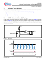
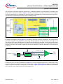
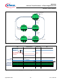
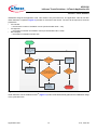
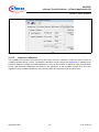
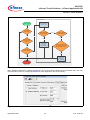
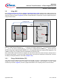
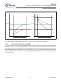
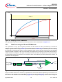
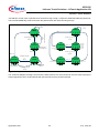
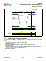
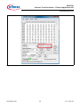
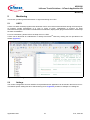
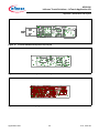
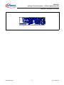
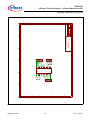
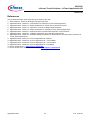
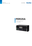
AP08126
Infineon Touch Solutions - inTouch Application Kit
Infineon’s Touch Solutions
VPAD
Area III
t
tuntouched
ttouched
Figure 22
Sampling result in CTM Method
After capacitance has been measured, the data is processed. This is elaborated in Chapter 3.2.3.
3.2.3
Data Processing for CR and CTM Methods
The capacitance of every pad is regularly measured and the results are further processed by an enhanced
adaptive average control function (Figure 23) in a software library (Chapter 3.2.4) provided by Infineon. A moving
average is generated and changes in the capacitance are detected. The average is derived by first accumulating
the capacitance measurement results. A noise suppression block ensures that the increase in the accumulated
result per sample is capped, to filter out noise spikes. The signal is then put through a first order low-pass filter to
enable detection of changes to the signal. The hysteresis offset increases the trip-point for touch (or decreases
the offset) after a pad touch is detected. This makes the touch more stable by preventing false finger releases. All
parameters are configurable.
LPF gain
total TSCTR * LPF gain
ADC Voltage
or
Charge Time
Σ
Noise
Suppression
total TSCTR
Low-Pass
Filter
Pad +
Averages
LowTrip
HighTrip
comp
+
Pad
Flags
+/-
hysteresis
offsets
Figure 23
Enhanced adaptive average control
Flags in variables will be set or cleared by an updated touch sense state machine depending on the nature of the
finger touch. The updated touch sense state machine has two versions (Figure 24). Version B is similar to the
touch sense state machine in the ROM library (Figure 13) and it supports tapping control. Version A supports
Application Note
19
V1.0, 2012-02