1
MVI46-AFC
SLC Platform
Gas and Liquid Flow Computer
User Manual
July 02, 2008
Please Read This Notice
Successful application of this module requires a reasonable working knowledge of the Rockwell Automation
hardware, the MVI46-AFC Module and the application in which the combination is to be used. For this
reason, it is important that those responsible for implementation satisfy themselves that the combination will
meet the needs of the application without exposing personnel or equipment to unsafe or inappropriate
working conditions.
This manual is provided to assist the user. Every attempt has been made to ensure that the information
provided is accurate and a true reflection of the product's installation requirements. In order to ensure a
complete understanding of the operation of the product, the user should read all applicable Rockwell
Automation documentation on the operation of the Rockwell Automation hardware.
Under no conditions will ProSoft Technology be responsible or liable for indirect or consequential damages
resulting from the use or application of the product.
Reproduction of the contents of this manual, in whole or in part, without written permission from ProSoft
Technology is prohibited.
Information in this manual is subject to change without notice and does not represent a commitment on the
part of ProSoft Technology Improvements and/or changes in this manual or the product may be made at any
time. These changes will be made periodically to correct technical inaccuracies or typographical errors.
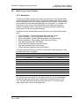
Battery Life Advisory
All modules in the MVI series use a rechargeable Lithium Vanadium Pentoxide battery to
backup the 512K SRAM memory, real-time clock, and CMOS. The battery should last for
the life of the module.
The module must be powered for approximately twenty hours before it becomes fully
charged. After it is fully charged, the battery provides backup power for the CMOS setup
and configuration data, the real-time clock, and the 512K SRAM memory for
approximately 21 days.
Before you remove a module from its power source, ensure that the battery within the
module is fully charged. A fully charged battery will hold the BIOS settings (after being
removed from its power source) for a limited number of days. When the battery is fully
discharged, the module will revert to the default BIOS settings.
Note: The battery is not user replaceable.
Your Feedback Please
We always want you to feel that you made the right decision to use our products. If you have suggestions,
comments, compliments or complaints about the product, documentation or support, please write or call us.
ProSoft Technology
1675 Chester Avenue, Fourth Floor
Bakersfield, CA 93301
+1 (661) 716-5100
+1 (661) 716-5101 (Fax)
http://www.prosoft-technology.com
Copyright © ProSoft Technology, Inc. 2000 - 2008. All Rights Reserved.
MVI46-AFC User Manual
July 02, 2008
PSFT.AFC.MVI46.UM.08.07.02
ProSoft Technology ®, ProLinx ®, inRAx ®, ProTalk® and RadioLinx ® are Registered Trademarks of
ProSoft Technology, Inc.
ProSoft® Product Documentation
In an effort to conserve paper, ProSoft Technology no longer includes printed manuals
with our product shipments. User Manuals, Datasheets, Sample Ladder Files, and
Configuration Files are provided on the enclosed CD and are available at no charge from
our web site: http://www.prosoft-technology.com
Printed documentation is available for purchase. Contact ProSoft Technology for pricing
and availability.
Asia Pacific: +603.7724.2080
Europe, Middle East, Africa: +33.5.34.36.87.20
Latin America: +1.281.298.9109
North America: +1.661.716.5100
Contents
MVI46-AFC ♦ SLC Platform
Gas and Liquid Flow Computer
Contents
PLEASE READ THIS NOTICE................................................................................................................ 2
Battery Life Advisory.......................................................................................................................... 2
Your Feedback Please ...................................................................................................................... 2
ProSoft® Product Documentation ..................................................................................................... 3
1
2
3
4
INTRODUCTION ............................................................................................................................... 9
1.1
Update Notice ..................................................................................................................... 10
1.2
MVI46-AFC Module ............................................................................................................ 11
QUICK START ................................................................................................................................ 13
2.1
Install AFC Manager........................................................................................................... 13
2.2
Install the Module in the Rack ............................................................................................ 14
2.3
Connect the AFC Module to the AFC Manager.................................................................. 15
2.4
Starting AFC Manager........................................................................................................ 17
2.5
Using AFC Manager ........................................................................................................... 17
2.6
Ladder Logic Implementation ............................................................................................. 23
2.7
Setting the Wallclock ..........................................................................................................24
2.8
Module Initialization ............................................................................................................ 25
METER CHANNEL FUNCTIONALITY ........................................................................................... 27
3.1
Meter Channels .................................................................................................................. 27
3.2
Linear (Pulse) Meter Overview ........................................................................................... 28
3.3
Differential (Orifice) Meter Overview .................................................................................. 29
3.4
Gas Product Overview........................................................................................................ 30
3.5
Liquid Product Overview..................................................................................................... 31
3.6
General Features................................................................................................................ 32
MODBUS DATABASE.................................................................................................................... 35
4.1
5
MODBUS COMMUNICATION ........................................................................................................ 41
5.1
6
Accumulator Totalizer and Residue ................................................................................... 47
ARCHIVES ...................................................................................................................................... 53
7.1
8
Communication Parameters ............................................................................................... 41
ACCUMULATORS.......................................................................................................................... 47
6.1
7
AFC Modbus Address Space ............................................................................................. 35
Archive Overview................................................................................................................ 53
EVENTS .......................................................................................................................................... 69
8.1
The Event Log .................................................................................................................... 69
8.2
Event Log structures...........................................................................................................70
8.3
Event Id Tag ....................................................................................................................... 71
ProSoft Technology, Inc.
July 2, 2008
Page 5 of 294
Contents
9
MVI46-AFC ♦ SLC Platform
Gas and Liquid Flow Computer
8.4
Event-triggered archives and accumulator resets ............................................................. 72
8.5
Period-end events .............................................................................................................. 72
8.6
Loggable events................................................................................................................. 73
8.7
Special events.................................................................................................................... 74
8.8
Site Datum Point events .................................................................................................... 75
8.9
Meter Datum Point events ................................................................................................. 75
8.10
Stream Datum Point events ............................................................................................... 77
8.11
"Rkv" notes......................................................................................................................... 79
8.12
Event numbers and Event Log Download ......................................................................... 79
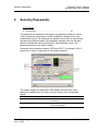
SECURITY (PASSWORDS) ........................................................................................................... 83
9.1
10
Hard Password................................................................................................................... 84
MVI46-AFC BACKPLANE COMMUNICATIONS .................................................................... 87
10.1
Backplane Communication and Supervisory Data ............................................................ 87
10.2
Data Integrity...................................................................................................................... 99
10.3
Data Validity and Module Initialization ............................................................................... 99
10.4
Module Scan .................................................................................................................... 101
10.5
Function Blocks................................................................................................................ 101
10.6
Wallclock Function ........................................................................................................... 102
10.7
Meter Process Input Function .......................................................................................... 103
10.8
Meter Analysis Function................................................................................................... 109
10.9
Meter Type and Product Group Summary....................................................................... 111
10.10
Meter Archive Fetch ......................................................................................................... 112
10.11
Modbus Gateway Function .............................................................................................. 112
10.12
Modbus Pass-Thru Function............................................................................................ 113
10.13
Modbus Master ................................................................................................................ 115
11
MVI46-AFC SAMPLE LADDER LOGIC ................................................................................ 117
11.1
Installing and Configuring the Module.............................................................................. 117
11.2
Sample Ladder and MVI46-AFC Version Compatibility................................................... 119
11.3
Data Files ......................................................................................................................... 120
11.4
Process Variables and Calculation Results Registers..................................................... 121
11.5
Sample Ladder................................................................................................................. 126
12
TROUBLESHOOTING ........................................................................................................... 141
12.1
User LEDs........................................................................................................................ 141
12.2
BBRAM LEDs................................................................................................................... 142
12.3
Meter Alarms.................................................................................................................... 142
12.4
Checksum alarms ............................................................................................................ 146
12.5
Events .............................................................................................................................. 146
12.6
Audit Scan........................................................................................................................ 146
13
REFERENCE.......................................................................................................................... 151
13.1
Page 6 of 294
General Specifications ..................................................................................................... 151
ProSoft Technology, Inc.
July 2, 2008
Contents
14
MVI46-AFC ♦ SLC Platform
Gas and Liquid Flow Computer
13.2
Measurement Standards ..................................................................................................154
13.3
Wedge Meter Applications................................................................................................159
13.4
Configurable Archive Registers ........................................................................................160
13.5
Archive Data Format.........................................................................................................164
13.6
Modbus Addressing Common to Both Primary and Virtual Slaves ..................................170
13.7
Modbus Port configuration................................................................................................264
13.8
Startup Basics and Frequently Asked Questions .............................................................265
13.9
Cable Connections ...........................................................................................................270
SUPPORT, SERVICE & WARRANTY ...................................................................................277
14.1
How to Contact Us: Technical Support ............................................................................277
14.2
Return Material Authorization (RMA) Policies and Conditions.........................................278
14.3
LIMITED WARRANTY......................................................................................................280
INDEX ..................................................................................................................................................285
ProSoft Technology, Inc.
July 2, 2008
Page 7 of 294
Contents
Page 8 of 294
MVI46-AFC ♦ SLC Platform
Gas and Liquid Flow Computer
ProSoft Technology, Inc.
July 2, 2008
Introduction
1
MVI46-AFC ♦ SLC Platform
Gas and Liquid Flow Computer
Introduction
In This Chapter
Update Notice........................................................................................ 10
MVI46-AFC Module ............................................................................... 11
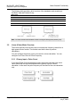
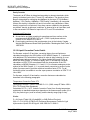
The MVI46-AFC Flow Computer module performs measurement of Hydrocarbon
Gases and Liquids using currently accepted industry measurement standards.
The module consists of a single-slot solution for Rockwell Automation chassis.
To obtain its process inputs for calculations, the module uses the process data
collected by analog and pulse I/O modules. The processor transfers this data to
the AFC module, which then calculates flow rates, accumulated volumes, and
accumulated mass. The results of the calculations are transferred back to the
processor for use in the application ladder logic, or for transfer to a SCADA host.
The module has two communication ports for Modbus communication allowing
easy access to a remote Modbus device. The module works as a Modbus slave
or master device.
As discussed later in this manual, the internal Modbus database can be
accessed by a Modbus Master device and by the processor (using the Modbus
Gateway Function).
The AFC Manager software can be used for easy meter configuration and
application monitoring. Refer to the AFC Manager User Manual for complete
information about this tool.
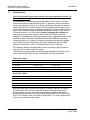
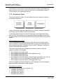
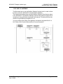
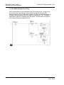
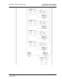
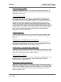
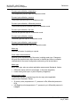
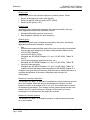
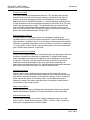
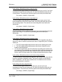
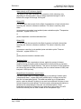
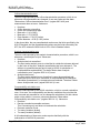
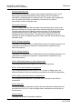
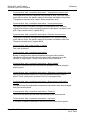
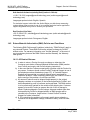
The following section provides a sample application where input data is
transferred from the transmitters to analog input cards on the Rockwell
Automation rack and the values are transferred from the processor to the module
(the module supports floating-point, scaled integer, or 4 to 20 mA format).
For Pulse meter applications, the pulse count and pulse frequency values are
typically transmitted through high-speed counter modules in the rack.
The module performs the flow calculation based on the values transferred
through the backplane. The calculation results can be read to the processor or
polled from a remote Modbus master unit connected to one of the communication
ports.
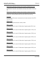
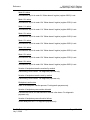
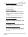
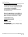
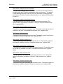
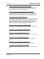
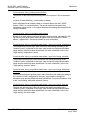
The following diagrams show examples of an application with an orifice meter
and gas product:
ProSoft Technology, Inc.
July 2, 2008
Page 9 of 294
MVI46-AFC ♦ SLC Platform
Gas and Liquid Flow Computer
1.1
Introduction
Update Notice
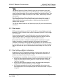
If your module measures liquids, please read this notice before upgrading from version 2.04
(or earlier) to 2.05 (or later).
For compliance with new measurement standards, the AFC version 2.05 has
introduced several new liquid product groups. In particular, the two non-refined
liquid product groups of version 2.04, which covered the entire density range of
crudes and NGLs, have each been split into two separate product groups, one
for the higher density range of crudes and the other for the lower density range of
NGLs. If your module has meter channels configured for either "Crude, NGL" or
"Oil-water emulsion", you should decide before upgrading the firmware the
new product group (light or heavy) to which each such channel should be
assigned. This assignment will be performed during the upgrade process and will
preserve all other configuration and historical records including accumulator
values and archives, in contrast to changing a product group after the upgrade
which resets the meter configuration and erases all historical records. Meter
channels configured for "Gas" or "Refined products" are not affected.
AFC Manager exhibits the same behavior when converting a project between
versions 2.04 (or earlier) and 2.05 (or later).
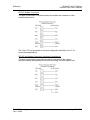
The criterion for assigning the new product group depends on the density units
and the Default Reference Density, as described in the following tables:
Density Units = kg/m3
Version 2.04 Product Group
Default Reference Density
Version 2.05 Product Group
Crude, NGL
= 0 OR ≥ 610.0
Crude oils, JP4
Crude, NGL
> 0 AND < 610.0
NGLs, LPGs
Oil Water Emulsion
= 0 OR ≥ 610.0
Oil-water emulsion (Crd)
Oil Water Emulsion
> 0 AND < 610.0
Oil-water emulsion (NGL)
Version 2.04 Product Group
Default Reference Density
Version 2.05 Product Group
Crude, NGL
= 0 OR ≥ 0.6100
Crude oils, JP4
Crude, NGL
> 0 AND < 0.6100
NGLs, LPGs
Oil Water Emulsion
= 0 OR ≥ 0.6100
Oil-water emulsion (Crd)
Oil Water Emulsion
> 0 AND < 0.6100
Oil-water emulsion (NGL)
Density Units = Rd/60
Due to roundoff error of numeric conversions, a Relative Density very close to
the cutoff value of 0.6100 may cause the module to assign the new product
group opposite to the one that was intended. Before upgrading, change the
Default Reference Density to a number significantly different from 0.6100, such
as 0.6110 (to target Crude) or 0.6090 (to target NGLs). You may change it back
to the correct value after the upgrade.
Page 10 of 294
ProSoft Technology, Inc.
July 2, 2008
Introduction
MVI46-AFC ♦ SLC Platform
Gas and Liquid Flow Computer
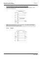
Density Units = API Gravity
1.2
Version 2.04 Product Group
Default Reference Density
Version 2.05 Product Group
Crude, NGL
= 0 OR ≤ 100.0
Crude oils, JP4
Crude, NGL
> 0 AND > 100.0
NGLs, LPGs
Oil Water Emulsion
= 0 OR ≤ 100.0
Oil-water emulsion (Crd)
Oil Water Emulsion
> 0 AND > 100.0
Oil-water emulsion (NGL)
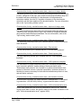
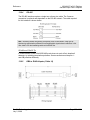
MVI46-AFC Module
ProSoft Technology, Inc.
July 2, 2008
Page 11 of 294
MVI46-AFC ♦ SLC Platform
Gas and Liquid Flow Computer
Page 12 of 294
Introduction
ProSoft Technology, Inc.
July 2, 2008
Quick Start
2
MVI46-AFC ♦ SLC Platform
Gas and Liquid Flow Computer
Quick Start
In This Chapter
Install AFC Manager.............................................................................. 13
Install the Module in the Rack ............................................................... 14
Connect the AFC Module to the AFC Manager ..................................... 15
Starting AFC Manager........................................................................... 17
Using AFC Manager .............................................................................. 17
Ladder Logic Implementation ................................................................ 23
Setting the Wallclock ............................................................................. 24
Module Initialization ............................................................................... 25
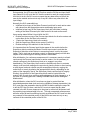
This section provides a general overview of the steps required to install and
configure the module. You should read the AFC Manager User Manual to obtain
a clear understanding of the steps outlined in this section.
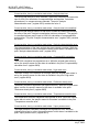
2.1
Install AFC Manager
The AFC Manager application is included on the CD-ROM shipped with your
module. Before you can use the application, you must install it on your computer.
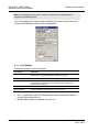
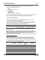
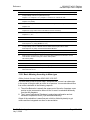
2.1.1 System Requirements
The following system requirements are the recommended minimum
specifications to successfully install and run AFC Manager:
Microsoft Windows compatible PC
Windows 2000 with Service Pack 2 or higher, or Windows XP Professional
with Service Pack 2 or higher, or Windows 2003.
300 mHz Pentium processor (or equivalent)
128 megabytes of RAM
20 megabytes of free disk space
Available serial port (COM port) or USB to Serial adapter cable with
necessary drivers, required for communication between AFC Manager
software and the AFC module.
DB9 adapter cable (included with module), required for connection between
PC serial port and AFC module (PTQ-AFC module does not require an
adapter).
ProSoft Technology, Inc.
July 2, 2008
Page 13 of 294
MVI46-AFC ♦ SLC Platform
Gas and Liquid Flow Computer
Quick Start
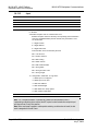
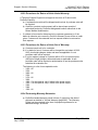
To install the AFC Manager application:
1
Insert the ProSoft Solutions CD in your CD-ROM drive. On most computers,
a menu screen will open automatically. If you do not see a menu within a few
seconds, follow these steps:
a
b
c
d
e
2
3
4
5
6
7
8
2.2
Click the Start button, and then choose Run.
In the Run dialog box, click the Browse button.
In the Browse dialog box, click "My Computer". In the list of drives,
choose the CD-ROM drive where you inserted the ProSoft Solutions CD.
Select the file prosoft.exe, and then click Open.
On the Run dialog box, click OK.
On the CD-ROM menu, click Documentation and Tools. This action opens a
Windows Explorer dialog box.
Open the Utilities folder, and then open the AFCManager folder.
Double-click the file Setup.exe. If you are prompted to restart your computer
so that files can be updated, close all open applications, and then click OK.
When your computer has finished restarting, begin again at Step 1.
Click OK or Yes to dismiss any confirmation dialog boxes.
It may take a few seconds for the installation wizard to start. Click OK on the
AFC Manager Setup dialog box to begin installing AFC Manager.
Follow the instructions on the installation wizard to install the program with its
default location and settings.
When the installation finishes, you may be prompted to restart your computer
if certain files were in use during installation. The updated files will be
installed during the restart process.
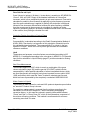
Install the Module in the Rack
If you have not already installed and configured your processor and power
supply, please do so before installing the AFC module. Refer to the processor
documentation for installation instructions.
Warning: You must follow all safety instructions when installing this or any other electronic
devices. Failure to follow safety procedures could result in damage to hardware or data, or even
serious injury or death to personnel. Refer to the documentation for each device you plan to
connect to verify that suitable safety procedures are in place before installing or servicing the
device.
After you have checked the placement of the jumpers, insert the AFC module
into the rack. Use the same technique recommended by the processor
manufacturer to remove and install AFC modules.
Warning: When you insert or remove the module while backplane power is on, an electrical arc
can occur. This could cause an explosion in hazardous location installations. Verify that power is
removed or the area is non-hazardous before proceeding. Repeated electrical arcing causes
excessive wear to contacts on both the module and its mating connector. Worn contacts may
create electrical resistance that can affect module operation.
Note: If you insert the module improperly, the system may stop working, or may behave
unpredictably.
Page 14 of 294
ProSoft Technology, Inc.
July 2, 2008
Quick Start
MVI46-AFC ♦ SLC Platform
Gas and Liquid Flow Computer
After you have installed the AFC module in the rack with the processor, you
should then download the sample program to the processor.
1
2
3
4
Connect a null modem cable from the serial port on your computer to the
serial port on the processor.
Start the configuration tool for your processor (RS Logix for MVI-AFC
modules; Concept, Unity or ProWorx for PTQ-AFC) and establish
communication with the processor.
Open the sample program in the configuration tool. Adjust the slot number
and processor type, if necessary, to match the physical configuration of the
processor and the position of the AFC module in the rack.
Download the program to the processor. The sample program is located on
the CD-ROM in the box with your module. Refer to the User Manual for your
module for specific instructions on downloading the sample program.
The next step is to connect your PC to the module to begin configuration with
AFC Manager.
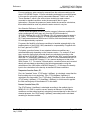
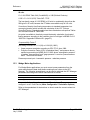
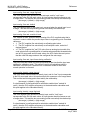
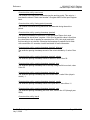
2.3
Connect the AFC Module to the AFC Manager
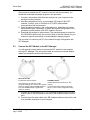
You will need the correct cables to connect the AFC module to the computer
running AFC Manager. The null-modem cable as well as any required adapter
cables are included in the box with the module.
Null-modem Cable
Included with all AFC modules
RJ45/DB-9 adapter
Connects directly to PTQ-AFC module
configuration/debug port, all other AFC modules
require an adapter cable (RJ45/DB9 adapter or
8 pin mini DIN/DB9 adapter, supplied with
module as needed).
Included with MVI46, 56, 69 and 71 AFC
modules
1
2
Connects Null-modem Cable to MVI46, 56,
69 and 71 AFC module configuration-debug
port.
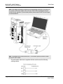
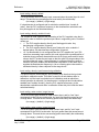
Connect the DB-9 adapter to the CFG (configuration/debug) port of the AFC
module (refer to the port labels on the front of the module to find the correct
port).
Connect the null-modem cable to the DB-9 adapter cable on the module, and
to an available serial port on your computer.
ProSoft Technology, Inc.
July 2, 2008
Page 15 of 294
MVI46-AFC ♦ SLC Platform
Gas and Liquid Flow Computer
Quick Start
Note: Some desktop and notebook computers are not equipped with a serial port. In this case, you
may require a USB to Serial adapter cable, with drivers. Not all USB to Serial adapters will work
correctly with this application. If you encounter problems, please contact ProSoft Technical Support
for recommendations.
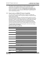
Note: The illustration above shows an MVI46-AFC. The connection process is similar for all MVIAFC and PTQ-AFC models.
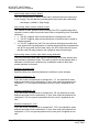
The null-modem cable that is supplied with the module uses the following
cabling scheme:
Page 16 of 294
ProSoft Technology, Inc.
July 2, 2008
Quick Start
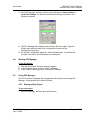
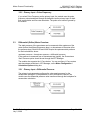
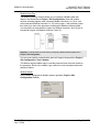
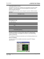
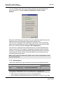
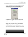
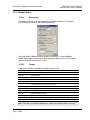
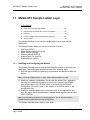
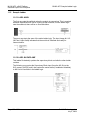
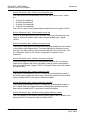
3
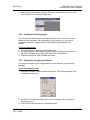
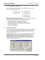
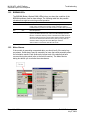
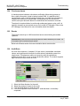
Start AFC Manager, and then select the port settings at: Communications /
Local Port Settings. The default communication settings are shown in the
following illustration.
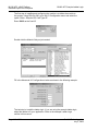
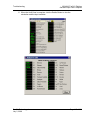
4
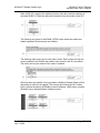
The AFC Manager will establish communication with the module. Open the
Project menu and then select Site Configuration to open the Site
Configuration dialog box.
On the Site Configuration dialog box, click the Read button. You should see
the word "Success" in the Result area of the dialog box.
5
2.4
MVI46-AFC ♦ SLC Platform
Gas and Liquid Flow Computer
Starting AFC Manager
To start AFC Manager:
1
2
3
2.5
Click the Start button, and then choose Programs.
In the Programs menu, choose ProSoft Technology.
In the ProSoft Technology menu, choose AFC Manager.
Using AFC Manager
The AFC module is configured with configuration files that you create using AFC
Manager. A configuration file is called a Project.
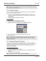
2.5.1 Starting a New Project
To start a new project:
1
Start AFC Manager, and then open the File Menu.
ProSoft Technology, Inc.
July 2, 2008
Page 17 of 294
MVI46-AFC ♦ SLC Platform
Gas and Liquid Flow Computer
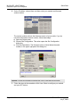
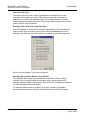
2
Quick Start
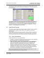
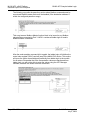
On the File Menu, choose New, and then select your module and firmware
version number.
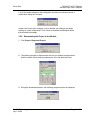
The version number refers to the firmware version of your module. If you do
not know the firmware version number, follow these steps:
a) Open the Project menu.
b) Choose Site Configuration. This action opens the Site Configuration
dialog box.
c) Click the Read button. The firmware version is listed below the serial
number, in the upper right part of the dialog box.
Important: You must be connected to the module and "online" to read data from the module.
3
Follow the steps in the remainder of this User Guide to configure your module
and your AFC device.
Page 18 of 294
ProSoft Technology, Inc.
July 2, 2008
Quick Start
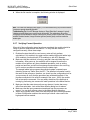
4
MVI46-AFC ♦ SLC Platform
Gas and Liquid Flow Computer
Before closing the program, open the File menu and choose Save As, to save
your project so you can open it again later.
2.5.2 Loading an Existing project
You can open and edit a project you have previously saved. Do this if you have
started, but not completed, the configuration of your project, or if you need to
modify the settings for a project that has already been downloaded to the
module.
To load an existing project:
1
2
3
Start AFC Manager, and then open the File menu.
On the File menu, choose Load. This action opens a dialog box that shows a
list of AFC Manager project files (AFC files) in the current folder.
Choose the project to load, and then click Open.
2.5.3 Printing the Configuration Report
You can print a report of your configuration for future reference, or for archival
purposes.
To print the configuration report:
1
Open the File menu, and then select Print Report. This action opens the Print
Configuration dialog box.
2
On the Print Configuration dialog box, select (check) the items to include in
the printed report.
Click Print to send the report to your default printer.
3
ProSoft Technology, Inc.
July 2, 2008
Page 19 of 294
MVI46-AFC ♦ SLC Platform
Gas and Liquid Flow Computer
Quick Start
Note: The size of the report depends on items you choose to include, and may require 75 pages or
more. Take this into account before printing.
2.5.4 Converting a Project
You can convert an existing project (configuration file) to use it with a different
module or firmware version. Do this if:
You want to reuse an application created for a different AFC module, for
example a project that was created for a PTQ-AFC that you want to use for
an MVI69-AFC.
You apply a firmware upgrade to a module.
To convert a project:
1
2
3
Open the File menu, and then choose Open.
Open the project (configuration file) to convert.
Open the Project menu, and then choose Change Module Type.
4
5
Choose the module type and firmware version from the menu.
Save your project.
Note: AFC Manager will save your updated configuration file with the same name as the file you
loaded. If you need to keep your original configuration, change the file name of your updated
configuration before saving.
2.5.5 Resetting Configuration Parameters
If you have modified your project (configuration file), or if you have loaded a
configuration file from disk, but you want to start a new project, you can reset the
configuration parameters back to their defaults without having to close and
reopen the AFC Manager.
To reset configuration parameters
1
2
3
Close any dialog boxes that are open.
Save the configuration file you were working on, if you would like to load it
again later.
On the File menu, choose Reset.
Note: This procedure has the same effect as choosing File / New / None.
Page 20 of 294
ProSoft Technology, Inc.
July 2, 2008
Quick Start
MVI46-AFC ♦ SLC Platform
Gas and Liquid Flow Computer
If you have made changes to the configuration that have not yet been saved, a
confirmation dialog box will open.
Answer Yes to save your changes, or No to discard your changes and begin
working on a new configuration. Click Cancel to abandon the attempted action
that caused this message.
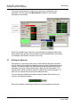
2.5.6 Downloading the Project to the Module
1
Click Project / Download Project.
2
The following window is displayed the first time you attempt communication
with the module. Enter the port parameters to use, and then click Done.
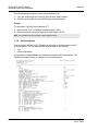
3
During the download operation, the following progress window is displayed:
ProSoft Technology, Inc.
July 2, 2008
Page 21 of 294
MVI46-AFC ♦ SLC Platform
Gas and Liquid Flow Computer
4
Quick Start
When the file transfer is complete, the following window is displayed:
Note: The virtual slave remapping data (page 37) is not downloaded during the procedure because
it requires a separate download operation.
Troubleshooting Tip: If the AFC Manager displays an "Illegal Data Value" message, it typically
indicates an invalid meter type or product group configuration. The module does not accept a
configuration file that attempts to change a meter type or product group for a meter that is currently
enabled. Disable all meters, change the meter types and product groups, and then enable the
meters again.
2.5.7 Verifying Correct Operation
When all of the configuration steps have been completed, the module should be
ready to perform measurement calculations. To verify that the module is
configured correctly, follow these steps:
1
2
Enable all meters that will be used, as any meter will only perform
calculations if it is enabled. Any meter can be enabled either with ladder logic
(MVI modules), function blocks (PTQ modules) or with AFC Manager.
Make sure that the wallclock is running, and that it has valid date and time
information. After power-up, the wallclock will be stopped, therefore the
module will not perform any time-scheduled operations, such as writing
period-end archives, and will not timestamp records written to the event log
until it receives a wallclock command from the ladder logic.
The sample ladder logic programs the wallclock update command upon
detecting "power-up" status from the AFC. The date/time information used is
the same as the processor, therefore you should use the configuration tool for
your processor to verify that the processor has valid date/time data. If the
processor wallclock is not valid (for example if the year = 1900), the module
will not accept the command. You may easily determine if the wallclock is
running by performing two consecutive read operations in the Meter Monitor.
3
4
5
Make sure that the meter does not have any alarms. A meter alarm may
affect flow calculation. Look at the Meter Monitor dialog box for alarms.
Make sure that the input parameters transferred from the processor are
correct. You can look at these values in the Meter Monitor dialog box.
When using a pulse meter, make sure that the pulse input rollover parameter
in Meter Configuration matches the actual input rollover value used in the
high speed counter module.
Page 22 of 294
ProSoft Technology, Inc.
July 2, 2008
Quick Start
2.6
MVI46-AFC ♦ SLC Platform
Gas and Liquid Flow Computer
Ladder Logic Implementation
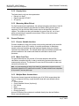
The sample ladder logic performs tasks that are covered in the Ladder Logic
sections of this manual. The most important task is to continuously write meter
process input variables from the processor to the module, and read calculation
results from the module to the processor.
Refer to the Ladder Logic sections for instructions on how to transfer the meter
process variables from the processor to the module. Ladder logic is required to
move the process variables to the correct data file or controller tag in the
processor.
The Meter Monitor window (Process Inputs field) displays the values that are
transferred from the processor.
ProSoft Technology, Inc.
July 2, 2008
Page 23 of 294
MVI46-AFC ♦ SLC Platform
Gas and Liquid Flow Computer
Quick Start
The values calculated by the module are continuously transferred to the
processor. You can refer to the Meter Monitor window to verify results
calculated by the module.
Refer to the Ladder Logic section for more information regarding the data files
and controller tags that store the calculation results transferred from the module
(for example, accumulator, flow rate, and so on).
2.7
Setting the Wallclock
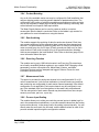
After power-up, the module must receive valid wallclock data from the ladder
logic to perform time-scheduled operations and to properly timestamp historical
records. The sample ladder logic automatically writes the wallclock during the
processor's first scan (using the processor's date and time information). You
should ensure that the processor contains valid date and time information. If it
does not, the module may not accept the wallclock block.
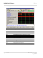
You can verify the wallclock information using the Meter Monitor section as
shown in the following example:
Refer to the Sample Ladder Logic section for more information on this topic.
Page 24 of 294
ProSoft Technology, Inc.
July 2, 2008
Quick Start
2.8
MVI46-AFC ♦ SLC Platform
Gas and Liquid Flow Computer
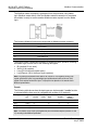
Module Initialization
When the module is powered up for the first time, both the OK and ERR BBRAM
LEDs are illuminated. This indicates that the module is in the Cold Start state and
is not yet ready to perform calculations. The following steps initialize the module:
Enable at least one meter
Set the processor to RUN mode
After these two steps are accomplished, the state is changed from Cold Start to
Released. This indicates that that module is ready to perform flow calculations.
When in the Released state, the OK LED is ON and the ERR LED is off.
When the module is ready, you will use AFC Manager to monitor meter
operation, archives, and events. The AFC Manager User Manual contains
detailed information on these tasks.
ProSoft Technology, Inc.
July 2, 2008
Page 25 of 294
MVI46-AFC ♦ SLC Platform
Gas and Liquid Flow Computer
Page 26 of 294
Quick Start
ProSoft Technology, Inc.
July 2, 2008
Meter Channel Functionality
3
MVI46-AFC ♦ SLC Platform
Gas and Liquid Flow Computer
Meter Channel Functionality
In This Chapter
3.1
Meter Channels ..................................................................................... 27
Linear (Pulse) Meter Overview .............................................................. 28
Differential (Orifice) Meter Overview ..................................................... 29
Gas Product Overview........................................................................... 30
Liquid Product Overview........................................................................ 31
General Features .................................................................................. 32
Meter Channels
The number of available meter channels depends on the platform as follows:
MVI46-AFC = 8 meters
MVI56-AFC = 16 meters
MVI69-AFC = 8 meters
MVI71-AFC = 8 meters
PTQ-AFC = 16 meters
Each meter channel can be assigned as a linear meter (pulse meter) input or as
a differential meter (orifice meter) input for flow measurement using either SI or
US units. Selecting the differential meter causes the module to use the AGA 3
standards for flow calculation. Selecting the linear meter causes the module to
use the AGA 7 standard for gas flow calculation.
Each meter channel can be configured for gas or liquid (crude or refined)
product. The Product Group essentially selects the API/AGA Standards to be
used in calculating flow rates/increments.
Selecting "Gas" causes use of AGA8 and either AGA3 or AGA7 Standards.
Selecting any liquid group causes use of the API2540 Standards. "Crude/LPG"
and "Oil-Water Emulsion" use the base, "A", and "E" tables 23/24/53/54, and
"Refined Products" uses the "B" tables 23/24/53/54. "Crude/LPG" is used for
propane, butane, NGLs (natural gas liquids), and crude oils which are relatively
water-free (less than 5 per cent. "Oil-Water Emulsion" is used for crude and
NGL/LPG that might have a high concentration of water for which API MPMS
Chapter 20.1 is applicable. "Refined Products" is used for gasoline, jet fuels, and
fuel oils.
ProSoft Technology, Inc.
July 2, 2008
Page 27 of 294
MVI46-AFC ♦ SLC Platform
Gas and Liquid Flow Computer
Meter Channel Functionality
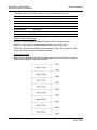
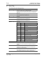
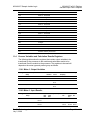
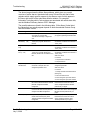
The following table provides a brief overview of the standards used according to
the Meter Type and Product Group:
Meter Type
Product Group
Standards
Differential
Gas
AGA8, AGA3
Differential
Liquid
API2540, AGA3
Linear
Gas
AGA8, AGA7
Linear
Liquid
API2540, MPMS ch12.2
Note: The meter channel must be disabled in order to change its meter type and product group.
3.2
Linear (Pulse) Meter Overview
The module typically receives the pulse count and pulse frequency values from a
high-speed counter module. The module uses these values to perform
calculations.
You can configure the primary input to be used for volume calculation. You can
configure it as Pulse Count or Pulse Frequency.
3.2.1 Primary Input = Pulse Count
If you select Pulse Count as the primary input, the module uses the pulse count
value transferred through the backplane as the primary input for volume
calculation. In this case, the pulse frequency will be used for flow rate calculation
only.
Page 28 of 294
ProSoft Technology, Inc.
July 2, 2008
Meter Channel Functionality
MVI46-AFC ♦ SLC Platform
Gas and Liquid Flow Computer
3.2.2 Primary Input = Pulse Frequency
If you select Pulse Frequency as the primary input, the module uses the pulse
frequency value transferred through the backplane as the primary input for both
flow accumulation and flow rate calculation. The pulse count value is ignored by
the module.
3.3
Differential (Orifice) Meter Overview
The static pressure of the gas stream can be measured either upstream of the
meter (before the differential pressure drop), or downstream of the meter (after
the pressure drop). Both AGA3 and AGA8 require the upstream static pressure
for their calculations, where:
upstream pressure = downstream pressure + differential pressure
If the pressure is measured from a downstream tap (typical), the Downstream
Static Pressure option should be set through the AFC Manager.
The module also supports the V-Cone device. You can configure V-Cone meters
and downstream selections in AFC Manager, on the Meter Configuration /
Calculation Options dialog box.
3.3.1 Primary Input = Differential Pressure
The primary input parameter configures the value used as source for the
accumulator calculation. If the parameter is set to Differential Pressure, the
module uses the differential pressure value transferred through the backplane for
accumulator calculation.
ProSoft Technology, Inc.
July 2, 2008
Page 29 of 294
MVI46-AFC ♦ SLC Platform
Gas and Liquid Flow Computer
Meter Channel Functionality
3.3.2 Primary Input = Flow Rate
You can configure the primary input parameter as flow rate in order to use this
value for the accumulator calculation.
Note: The flow rate can be converted to a different unit.
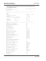
The AFC Manager software supports the following parameters:
3.4
Orifice Plate and Meter Tube Measured Diameter
Orifice Plate and Meter Tube Measurement Temperature
Orifice Plate and Meter Tube, Coefficient of Thermal Expansion
DP Flow Threshold (kPa)
DP Alarm Threshold (kPa)
Gas Product Overview
The gas compressibility calculations are based on molar analysis concentrations
of up to 21 components, using the Detail Characterization Method of AGA8
(1992). The module automatically generates alarms if the sum of the molar
concentrations is not 100%
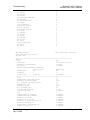
Configure the analysis settings using the AFC Manager (Meter Configuration /
Analysis Config) as follows. This window allows the selection of the
components(Component Selection Map) and stream precision (Precision and
Stream Assignment – version 2.06.000 or higher). The sample ladder logic
assumes that all components are selected so check all components at the
Component Selection Map window.
Page 30 of 294
ProSoft Technology, Inc.
July 2, 2008
Meter Channel Functionality
MVI46-AFC ♦ SLC Platform
Gas and Liquid Flow Computer
Enter the gas analysis concentrations by clicking at the Analysis button.You can
also update the concentrations through the backplane as it will be later shown at
this User Manual.
The module records events every time a molar concentration value changes. For
applications that involve gas chromatograph devices, this feature might not be
desirable because it is expected that the values should frequently change. You
can disable this feature using AFC Manager (Meter Configuration / Control
Options / Treat Analysis as Process Input).
3.5
Liquid Product Overview
The module supports applications involving crude or refined oil such as crude oil,
oil/water emulsion, propane, butane, NGLs, LPGs, gasoline, jet fuels and
lubricating oils.
When measuring liquids with density correction, density at flowing conditions is
required. This value may be provided directly as a process input, or the module
can calculate a density from the frequency provided by a densitometer device.
3.5.1 To use a densitometer
Follow the steps below to use a densitometer.
1
2
Configure it, entering all configuration parameters directly from the calibration
data sheet supplied by the densitometer manufacturer.
Supply the frequency output from the densitometer in Hz as a floating-point
value in the "Flowing density" process-input location over the backplane
(refer to the Backplane Communication section for your platform in the
MVI46-AFC manual to determine the correct location). The AFC then
calculates a flowing density value, which is then validated by the range check
mandated by the "Density" values of "Process Input Scaling" of the meter
configuration. The "Scaling" sub-selection is not used against the frequency
input, however; the frequency is always input as floating-point.
Note: If using the Densitometer feature, select the Density Process Input Scaling for 4 to 20mA
and enter the densitometer frequency as a floating-point value.
ProSoft Technology, Inc.
July 2, 2008
Page 31 of 294
MVI46-AFC ♦ SLC Platform
Gas and Liquid Flow Computer
Meter Channel Functionality
3.5.2 Density Units
The liquid density units can be expressed as:
Density is in kg/m3;
Relative density 60ºF/60ºF;
API gravity;
3.5.3 Measuring Water Diluent
For liquid measurement applications, the optional automatic calculation of Net Oil
Volume and mass based on the Sediment and Water (S&W) percent input is
supported. Only provide the S&W percent value in the specified controller
register. The module puts the gross standard (or gross clean oil), net oil and
water accumulations in separate accumulators. Refer to Net Accumulator
Calculation (page 51).
3.6
General Features
3.6.1 Process Variable Interface
Process variables for each of the meter runs must be produced by the controller
for consumption by the AFC module. A versatile architecture for backplane
transfer of process variables and other data and signals allow you to easily
implement the data transfer. The sample ladder logic automatically transfers the
process variables to the module and reads the calculation results to the
processor.
3.6.2 Meter Scan Time
For good measurement, the process I/O must be sampled, and the flow
calculations completed quickly in order to avoid losing process information and
measurement accuracy. The process I/O scan time for the module is under one
second for all meter runs.
Note: This is time-dependent on design of the ladder logic implemented to support the two-way
data transfer between the AFC module and the controller. The meter calculation scan independent
of the process I/O scan may take longer.
3.6.3 Multiple Meter Accumulators
Each meter channel supports the following set of full 32-bit accumulators that
may be configured in binary or split decimal format with user-defined rollover
values:
Gross Volume
Gross Standard Volume (liquid only)
Net Volume
Mass
Water (liquid only)
Energy (gas only)
Access to the above accumulators is available directly from the two Modbus
Slave communications ports.
Page 32 of 294
ProSoft Technology, Inc.
July 2, 2008
Meter Channel Functionality
MVI46-AFC ♦ SLC Platform
Gas and Liquid Flow Computer
3.6.4 Product Batching
Any or all of the available meter runs may be configured for field installation that
requires shipping and/or receiving product batches of predetermined size. The
configuration utility option of selecting resettable accumulators provides a simple
way to use the power of ladder logic to design product batching, monitoring, and
control tailored to suit specific field requirements.
The Meter Signals feature can be used to create an archive or reset an
accumulator after the batch is concluded. Refer to the Ladder Logic section for
your platform for more information on using this feature.
3.6.5 Data Archiving
The module supports the archiving of data for each meter channel. Each time,
one record consisting of all the associated data is date and time stamped and
archived. This option allows for archiving each hour for 2 days (48 records per
meter run) and every day for 35 days (35 daily records per meter run) for each
meter channel. Each record consists of up to 40 process and other variables.
Archives are mapped to the local Modbus Table. Refer to Archives (page 53) for
more information about this topic.
3.6.6 Event Log Function
The module can log up to 1999 critical events in an Event Log File stored as a
set of easily accessible Modbus registers in non-volatile RAM. Changing critical
parameters, such as orifice plate size, Meter Base K factors, and Meter
Correction Factors, are time stamped and logged. Refer to Events for more
information about this topic.
3.6.7 Measurement Units
This option is provided for each meter channel to be configured with SI or US
units of measurement. Units for flow totalization (volumetric and mass) and flow
rate monitoring are configurable for each meter channel separately if the default
configuration is not applicable. Each meter channel may be configured to use
any of the standard units from liters/gallons to thousand cubic meters/barrels.
The flow rate period of each meter channel may be selected from flow rate per
second, per minute, per hour, or per day.
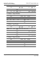
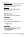
3.6.8 Process Input Scaling
The module allows you to either pre-scale the process inputs via ladder logic for
use in the measurement calculations, or provide unscaled values from the analog
input modules directly. In the second case, the scaling is done internally. You can
directly enter the zero-scale, the full-scale, and the default values for each of the
process variable inputs through the configuration window.
ProSoft Technology, Inc.
July 2, 2008
Page 33 of 294
MVI46-AFC ♦ SLC Platform
Gas and Liquid Flow Computer
Meter Channel Functionality
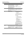
Scaled Integer
Variable
Format
Example
Temperature
Two decimal places implied
A value of 1342 would be equivalent
to 13.42°C
Pressure
No decimal places implied for SI
units (kPa) and one decimal
place implied for U.S. units
(psi).
A value of 200 would be equivalent
to 200kPag
Differential Pressure
Two decimal places implied for
inches of H2O and 3 places for
kPa
A value of 35142 would be
equivalent to 35.142kPa
Density (kg/m3)
One implied decimal place
A value of 5137 would be equivalent
to 513.7 kg/m3
Density (Relative Density)
Four implied decimal places
A value of 10023 would be
equivalent to 1.0023 60F/60F.
Density (API)
Two implied decimal places
A value of 8045 would be equivalent
to 80.45 °API.
In the Meter Monitor window, the raw value is shown at the "Last Raw" column
and the converted values are shown at the "Scaled Avg" column.
When selecting the 4 to 20mA process input scaling, the module uses the
following ranges:
4 to 20mA
Processor
Module
0%
100%
SLC
MVI46-AFC
3277
16384
ControlLogix
MVI56-AFC
13107
65535
CompactLogix
MVI69-AFC
6241
31206
PLC
MVI71-AFC
819
4095
Quantum/Unity
PTQ-AFC
4000
20000
The module uses the configured values for zero and full scale to interpret the
process input scaling.
Page 34 of 294
ProSoft Technology, Inc.
July 2, 2008
Modbus Database
4
MVI46-AFC ♦ SLC Platform
Gas and Liquid Flow Computer
Modbus Database
In This Chapter
AFC Modbus Address Space ................................................................ 35
The module supports two individual Modbus slaves (Primary and Virtual) to
optimize the polling of data from the remote SCADA system, or from the
processor (through the backplane). Refer to the Modbus Dictionary dialog box in
AFC Manager for information about Modbus addressing.
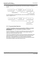
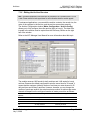
4.1
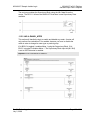
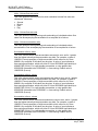
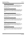
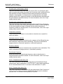
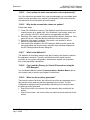
AFC Modbus Address Space
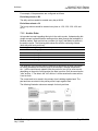
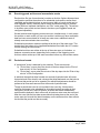
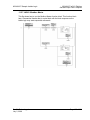
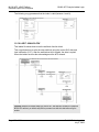
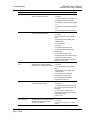
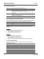
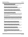
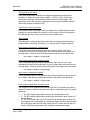
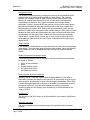
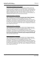
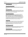
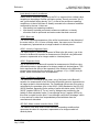
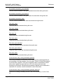
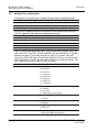
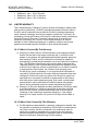
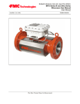
Addressable Modbus registers are divided into four banks as shown in the
following figure:
MODBUS Address Space Allocation: Total MB Registers: 131,072
Primary Slave Banks
Virtual Slave Banks
(131072 registers)
(20,000 registers)
Holding Registers
Input Registers
Holding Registers
Input Registers
From: 0
From: 0
From: 0
From: 0
To: 65535
To: 65535
To: 9999
To: 9999
The first 100 registers of the virtual slave (registers 0 through 99) are predefined
to map to the first 100 registers of the primary slave. This mapping cannot be
changed. Also, the Virtual Slave Input Registers can be accessed as Virtual
Slave Holding Registers by adding 10000 to the Modbus register address; for
example, Input Register 2386 is the same as Holding Register 12386.
4.1.1 Primary Slave
The Primary Slave contains the main AFC database that consists of 131,072
Modbus registers. The Site and Meter configuration, as well as all live process
data and ongoing calculations are kept in the Primary Slave address space. This
address space is divided equally between the Input Register Bank (65,536
registers) and the Holding Register Bank (65,536).
The register addressing is shown in the Modbus Dictionary dialog box in AFC
Manager.
Modbus Address References
In these documents (the AFC Manager User's Guide and the User's Guide for
your platform) you will occasionally see Modbus address references like
Ph00018 or Mh00162. The first two characters of such references indicate how
to convert the following number into an absolute Modbus address in the module.
ProSoft Technology, Inc.
July 2, 2008
Page 35 of 294
MVI46-AFC ♦ SLC Platform
Gas and Liquid Flow Computer
Modbus Database
This table shows the possible values for the first identification character:
Address Translation ID
Description
P
Absolute Modbus address, Primary Slave
M
Meter-relative Modbus address, Primary Slave
V
Absolute Modbus address, Virtual Slave
This table shows the possible values for the second identification character:
Register Bank ID
Description
h
Holding register
i
Input register
Modbus Address Examples
Ph02000 = holding register located at address 2000 in the primary slave
Pi02000 = input register located at address 2000 in the primary slave
Mh00100 = Meter-relative holding register located at offset 100 in the block of the
primary slave that contains the data for the meter
Meter-relative Data
Meter-relative data starts at absolute holding register address 8000 and occupies
2000 words of data for each meter channel.
Page 36 of 294
ProSoft Technology, Inc.
July 2, 2008
Modbus Database
MVI46-AFC ♦ SLC Platform
Gas and Liquid Flow Computer
The meter-relative addresses are offsets within each meter data area. The
correct absolute address is calculated by the following formula:
[absolute address] = [meter-relative address] + (8000)*[meter number-1]
In the Modbus Dictionary dialog box, addresses listed for the selected meter are
absolute addresses, so you should subtract the appropriate multiple of 8000 to
calculate the meter-relative address.
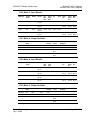
Example: Find the orifice diameter address for the first 5 meter channels.
The meter 1 orifice diameter registers are located at the holding register address
8162 and 8163 as follows:
8160
8161
Float
Parameter: orifice plate: measurement temperature
8162
8163
Float
Parameter: orifice plate: measured diameter
8164
8165
Float
Parameter: orifice plate: coef of thermal expansion
8166
8167
Float
Parameter: meter tube: measurement temperature
8168
8169
Float
Parameter: meter tube: measured diameter
8170
8171
Float
Parameter: meter tube: coef of thermal expansion
8172
8173
Float
Parameter: differential pressure flow threshold
The meter-relative addresses are Mh00162 and Mh00163
The addresses for meters 1 to 5 are listed on the following table:
Meter
Registers
1
8162 and 8163
2
10162 and 10163
3
12162 and 12163
4
14162 and 14163
5
16162 and 16163
Scratchpad
The Primary Modbus Slave contains a scratchpad area that can be used to store
any data required by each application. This area is "empty" by default and
contains 6000 words of data starting at holding register 2000 in the Primary
Modbus Slave.
Virtual Slave
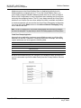
The module also provides a Virtual Address Space of 20,000 Modbus registers.
This address space is divided equally between the Input Register Bank (10,000
registers) and the Holding Register Bank Holding Register Bank (10,000). This is
where you can create a virtual re-map by cross-referencing any of the 130,072
Primary Slave Modbus registers to the 20,000 Modbus registers in the Virtual
Slave Banks, thereby making it easy for a SCADA Master to poll only the
necessary Modbus addresses in contiguous blocks. The virtual slave can also be
used for data polling from the processor through the backplane.
ProSoft Technology, Inc.
July 2, 2008
Page 37 of 294
MVI46-AFC ♦ SLC Platform
Gas and Liquid Flow Computer
Modbus Database
Modbus access to the Virtual Modbus Slave is disabled by default since its
Modbus address is originally set as 0. To use the Virtual Modbus Slave, you
must initially configure a Modbus address greater than zero in order to enable it.
Refer to Site Configuration for more information about enabling the Virtual Slave
and using the remapping feature. The PLC may always access the Virtual Slave,
whether or not it has a non-zero slave address and thus is available via Modbus.
A download operation will not transfer the Virtual Slave Remapping configuration.
You must click on the Write button on the Indirect Address Remapping dialog
box to transfer the data.
Note: The first 100 registers in the Virtual Slave Holding Register Bank have been pre-assigned
and cannot be remapped. They map directly to the first 100 holding registers of the Primary Slave.
Virtual Slave Example Application
Assume that an application requires a remote Modbus master to poll the orifice
diameters for the first 5 channels. Continuing the previous example, the holding
register addresses are listed again the following table.
Meter
Registers
1
8162 and 8163
2
10162 and 10163
3
12162 and 12163
4
14162 and 14163
5
16162 and 16163
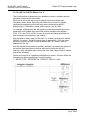
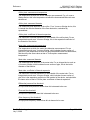
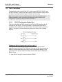
Because these addresses are not contiguous, the Modbus master would have to
use five commands to poll all the data directly from the Primary Modbus Slave as
follows:
Page 38 of 294
ProSoft Technology, Inc.
July 2, 2008
Modbus Database
MVI46-AFC ♦ SLC Platform
Gas and Liquid Flow Computer
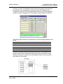
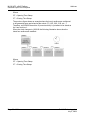
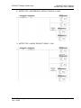
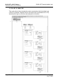
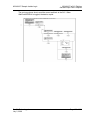
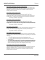
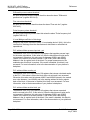
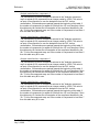
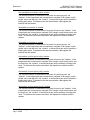
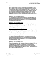
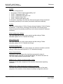
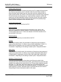
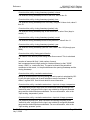
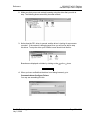
However, using the Virtual Modbus Slave optimizes the polling of data because
the registers can be remapped in any order using the AFC Manager (Site
Configuration window). The following illustration shows how the orifice diameter
registers could be remapped to the Virtual Slave starting at address Vh00100:
The following table shows how the addresses would be remapped between both
slaves:
Primary Modbus Slave Addresses
Virtual Modbus Slave Addresses
8162 and 8163
100 and 101
10162 and 10163
102 and 103
12162 and 12163
104 and 105
14162 and 14163
106 and 107
16162 and 16163
108 and 109
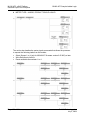
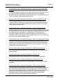
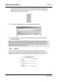
Therefore, instead of sending five Modbus commands (2 words each) to the
Primary Modbus Slave, the Modbus master device can now send one single
Modbus command (10 words) to the Virtual Modbus Slave in order to poll the
same data from the module:
ProSoft Technology, Inc.
July 2, 2008
Page 39 of 294
MVI46-AFC ♦ SLC Platform
Gas and Liquid Flow Computer
Modbus Database
This example demonstrates the benefits of using the Virtual Slave instead of
accessing the data directly from the Primary Modbus Slave. The same procedure
can be used when polling data from the processor (through the backplane)
because the Modbus Gateway block also requires the data to be listed in a
contiguous order.
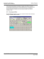
4.1.2 Accessing the Data
The AFC Manager provides an easy way to read and write data from both slaves
through the Modbus Master Interface.
Page 40 of 294
ProSoft Technology, Inc.
July 2, 2008
Modbus Communication
5
MVI46-AFC ♦ SLC Platform
Gas and Liquid Flow Computer
Modbus Communication
In This Chapter
Communication Parameters .................................................................. 41
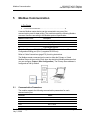
A remote Modbus master device can be connected to any one of the
communication ports for data polling. The module accepts the following Modbus
command functions according to the Modbus protocol specification:
Modbus Function Code
Description
3
Read Holding Registers
4
Read Input Registers
6
Preset Single Register
16
Preset Multiple Registers
Ports 2 and 3 support RS-232, RS-422, or RS-485 communications. The
Configuration/Debug port (Port 1) supports RS-232 only.
Refer to Cable Connections (page 270) for wiring instructions.
The Modbus master command can be sent to either the Primary or Virtual
Modbus Slaves in the module. Each slave has individual Modbus addresses that
you can configure (Project / Site Configuration). The Primary Slave address is
configured as 244 by default.
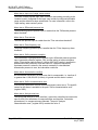
5.1
Communication Parameters
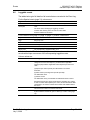
The module supports the following communication parameters for each
communication port:
Parameter
Values
Baud Rate
300, 600, 1200, 2400, 4800, 9600 or 19200
Data Bits
7 or 8
Stop Bits
1 or 2 Bits
Mode
RTU or ASCII
Parity
None, Even or Odd
ProSoft Technology, Inc.
July 2, 2008
Page 41 of 294
MVI46-AFC ♦ SLC Platform
Gas and Liquid Flow Computer
Modbus Communication
Note: Do not configure a port for both RTU mode and 7 data bits as this combination is not
supported by the Modbus protocol.
You must configure the communication parameters for each communication port
using the AFC Manager software (Site Configuration):
5.1.1 Port Options
The following options can be configured:
Port Options
Description
Hide Primary Slave
Protects the Primary Slave from any read or write operation from a
remote master. Only the virtual slave is visible on this port.
Swap Modbus Bytes
Swap the Modbus bytes transferred through this port (Not implemented)
Swap Modbus Words
Swap the Modbus words transferred through this port. This parameter is
only applicable to those data points that hold 32-bit quantities (long
integers, floats, totalizers),
Disable Pass-Thru
Disables the pass-thru feature on this port
Modbus Master
Enables the Modbus master for the port (Port 3 only)
Not all options are available on every port:
Port 1 is restricted, so that AFC Manager can always communicate with the
Primary Slave using this port.
Modbus Master option is available only on Port 3.
Page 42 of 294
ProSoft Technology, Inc.
July 2, 2008
Modbus Communication
MVI46-AFC ♦ SLC Platform
Gas and Liquid Flow Computer
Modbus Pass-Thru
The Modbus pass-thru feature allows you to configure a Modbus pass-thru
region in the Virtual Slave (Project / Site Configuration). After the module
receives a holding register write command (Modbus functions 6 or 16) or a bit
write command (Modbus functions 5 or 15) to this region, it will generate a passthru block to be sent to the processor containing the Modbus command data.
You may define a word pass-thru region (for Modbus functions 6 and 16) and a
bit pass-thru region (for Modbus functions 5 and 15).
Important: You must enable the virtual slave by configuring a Modbus address greater than 0
(Project / Site Configuration).
You can control which communication ports will support the pass-thru (Project /
Site Configuration / Port X button).
This feature requires ladder logic to read the pass-thru block from the module to
the processor. Refer to the Ladder Logic section for more information about the
pass-thru feature.
Modbus Master
Port 3 can be configured for Modbus master operation (Project / Site
Configuration / Port 3).
ProSoft Technology, Inc.
July 2, 2008
Page 43 of 294
MVI46-AFC ♦ SLC Platform
Gas and Liquid Flow Computer
Modbus Communication
The Modbus master command is generated from the processor using ladder
logic (Modbus master block). After the Modbus master transaction is completed
the module is ready to receive another Modbus master request from the ladder
logic:
The following Modbus functions are supported for Modbus master operation:
Modbus Function Code
Description
1
Read Coil Status
2
Read Input Status
3
Read Holding Registers
4
Read Input Registers
15
Force Multiple Coils
16
Preset Multiple Registers
The module offers considerable flexibility for Modbus master operation, allowing
the ladder logic to select one of the following data types:
Bit (packed 16 to a word)
Word (16-bit register)
Long (32-bit items as register pairs)
Long Remote (32-bit items as single registers)
Note: Long data type implements each data unit as one pair of 16-bit registers (words). Each
register contains two bytes. Long remote data type implements each data unit as one 32-bit
register. Each register contains four bytes. The proper choice depends on the remote slave's
Modbus implementation.
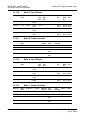
Example
The following table shows how the data types are implemented if a write function
is selected and the item count is configured with a value of 10 (decimal):
Data Type
Register
Type
Modbus
Function
Number
of Coils
Number of
Bytes
Number of
Registers
Number of words
(16-bits)
transferred
Bit
Coil
15
10
2
-
1
Word
Holding
16
-
20
10
10
Long
Holding
16
-
40
20
20
Long Remote
Holding
16
-
40
10
20
Note: The number of coils, bytes, and registers are part of the Modbus request (functions 15 and
16) according to the Modbus specification.
Page 44 of 294
ProSoft Technology, Inc.
July 2, 2008
Modbus Communication
MVI46-AFC ♦ SLC Platform
Gas and Liquid Flow Computer
The following table shows how the data types are implemented if a read function
is selected and the item count is configured with a value of 10 (decimal):
Data Type
Register Type
Modbus Function
Number of Registers
Bit
Coil
1
10
Bit
Input
2
10
Word
Holding
3
10
Word
Input
4
10
Long
Holding
3
20
Long
Input
4
20
Long Remote
Holding
3
10
Long Remote
Input
4
10
Note: The number of registers is part of the Modbus request according to the Modbus
specification.
Refer to the ladder logic section for your module for more information about the
Modbus master block.
ProSoft Technology, Inc.
July 2, 2008
Page 45 of 294
MVI46-AFC ♦ SLC Platform
Gas and Liquid Flow Computer
Modbus Communication
Page 46 of 294
ProSoft Technology, Inc.
July 2, 2008
Accumulators
6
MVI46-AFC ♦ SLC Platform
Gas and Liquid Flow Computer
Accumulators
In This Chapter
Accumulator Totalizer and Residue....................................................... 47
The accumulators store the current amount of measured quantity for a meter
channel. This section provides detailed information about the accumulators.
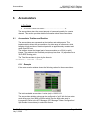
6.1
Accumulator Totalizer and Residue
The accumulators are expressed as the totalizer and residue parts. This
implementation allows the accumulation of a wide range of increments, while
keeping a high precision of fractional part with an approximately constant and
small round off error.
The totalizer stores the integral part of an accumulator as a 32-bit (or split)
integer. The residue is the fractional part (always less than 1.0) expressed as a
32-bit IEEE floating point.
The Total Accumulator is given by the formula:
ACCUMULATOR = TOTALIZER + RESIDUE
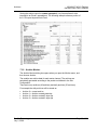
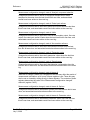
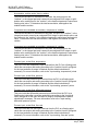
6.1.1 Example
If the meter monitor window shows the following values for the accumulators:
The total resettable accumulator 1 value (net) is 12.8031153.
The accumulator totalizer values can be configured to "split" with the low-order
word rolling over from 9999 to 0000 at which time the high-order word is
incremented. Refer to the AFC Manager (AFC Manager / Meter Configuration /
Split Double Accumulators) to select this feature.
ProSoft Technology, Inc.
July 2, 2008
Page 47 of 294
MVI46-AFC ♦ SLC Platform
Gas and Liquid Flow Computer
Accumulators
A 32-bit value is more suited to computation and has a greater range than a split
value, whereas a split value is easier to read when it is represented as a pair of
16-bit numbers, as in a processor data file.
6.1.2 Accumulator Types
The module supports a total of 12 accumulators per meter channel divided into
the following categories:
These 3 accumulator types are independent. For example, resetting a resettable
accumulator does not affect the other accumulators.
For multiple-stream firmware (version 2.05 and later), each stream also has its
own set of ten accumulators (six non-resettable and four resettable). Increments
are applied both to the meter accumulators and to the accumulators for the active
stream.
Non-Resettable Accumulators
The non-resettable accumulators are only reset when the accumulator rollover
value is reached. The accumulator rollover value, and the accumulator unit must
be configured using the AFC Manager. Refer to the AFC Manager User Manual
for more information about this topic.
The module supports six non-resettable accumulators in order to show the
measured quantity to be totalized:
Non-resettable accumulator mass
Non-resettable accumulator energy (Gas applications only)
Non-resettable accumulator net
Non-resettable accumulator gross
Non-resettable accumulator gross standard (Liquid applications only). For OilWater Emulsion, this is non-resettable accumulator gross clean oil.
Non-resettable accumulator water (Liquid applications only)
Refer to the Modbus Dictionary dialog box in AFC Manager for more information
about the Modbus addresses for these registers.
Resettable Accumulators
The resettable accumulators are referred to as:
Resettable Accumulator 1
Resettable Accumulator 2
Resettable Accumulator 3
Resettable Accumulator 4
Page 48 of 294
ProSoft Technology, Inc.
July 2, 2008
Accumulators
MVI46-AFC ♦ SLC Platform
Gas and Liquid Flow Computer
Configuring Resettable Accumulators
Resettable Accumulators are configured from the Resettable Accumulator Select
dialog box. To open this dialog box, click the Resettable Accum button on the
Meter Configuration dialog box.
Each Resettable Accumulator can be configured to represent a different quantity
as follows:
Accumulator
Modbus address for accumulator
select (Meter-relative)
Default Value
Resettable accumulator 1
136
Net (code 3)
Resettable accumulator 2
137
Gross (code 4)
Resettable accumulator 3
138
Gross Standard (code 5)
Resettable accumulator 4
139
Mass (code 1)
Valid Configuration Codes
The valid codes are:
Code
Quantity
0
None
1
Mass
2
Energy (Gas Only)
3
Net
4
Gross
5
Gross Standard (Liquid Only)
6
Water (Liquid Applications Only).
For example, moving a value of 4 to holding register 8136 will configure Meter 1's
resettable accumulator 1 as "Gross Volume". Moving "0" to holding register
10138 configures Meter 2's Resettable Accumulator 3 to accumulate nothing
(takes it out of service).
The resettable accumulators are reset when one of the following situations occur.
Reset from AFC Manager
You may reset any of the resettable accumulators using the AFC Manager
(Meter Monitor):
ProSoft Technology, Inc.
July 2, 2008
Page 49 of 294
MVI46-AFC ♦ SLC Platform
Gas and Liquid Flow Computer
Accumulators
Reset from Ladder Logic
The ladder logic may send a meter signals block to command one or more
resettable accumulators to be reset. This feature is especially important for
applications involving field installations that require shipping and/or receiving
product batches of predetermined size. Refer to the Ladder Logic section for your
module type for more information.
Reset Upon Archive Period End or Reset Upon Event
Use AFC Manager to configure the resettable accumulator to be reset when the
archive period ends or when an event occurs. Refer to Event Log in the AFC
Manager User Guide for more information on configuring and monitoring events.
Refer to Archives (page 53) for more information.
Reset When the Accumulator Rollover Value is Reached
The resettable accumulator is reset when the accumulator rollover value is
reached. You must configure the accumulator rollover value using the AFC
Manager software (Meter Configuration). Refer to the AFC Manager User Manual
for more information about this subject.
For multiple-stream firmware (version 2.05 or later), resetting a resettable
accumulator resets that accumulator for both the meter and for all its streams.
Page 50 of 294
ProSoft Technology, Inc.
July 2, 2008
Accumulators
MVI46-AFC ♦ SLC Platform
Gas and Liquid Flow Computer
6.1.3 Archive Accumulators
The archive accumulators are part of the current archive (archive 0) data. These
accumulators are automatically reset when a new archive is generated. The
following Modbus holding registers are used:
Daily Archive
Hourly Archive
Meter
Accumulator:
Totalizer
Accumulator: Residue
Accumulator:
Totalizer
Accumulator: Residue
1
8890 to 8891
8892 to 8893
8894 to 8895
8896 to 8897
2
10890 to 10891
10892 to 10893
10894 to 10895
10896 to 10897
3
12890 to 12891
12892 to 12893
12894 to 12895
12896 to 12897
4
14890 to 14891
14892 to 14893
14894 to 14895
14896 to 14897
5
16890 to 16891
16892 to 16893
16894 to 16895
16896 to 16897
6
18890 to 18891
18892 to 18893
18894 to 18895
18896 to 18897
7
20890 to 20891
20892 to 20893
20894 to 20895
20896 to 20897
8
22890 to 22891
22892 to 22893
22894 to 22895
22896 to 22897
You can view the addresses, datum types and descriptions in the Modbus
Dictionary dialog box.
You may configure the accumulator quantity to be used for each archive
accumulator using the AFC Manager (Meter Configuration / Archive Config /
Accumulator Select):
6.1.4 Net Accumulator Calculation
The Net Accumulator Calculation depends on the product group (gas or liquid).
For gas applications, the Net Accumulator is calculated as follows:
ProSoft Technology, Inc.
July 2, 2008
Page 51 of 294
MVI46-AFC ♦ SLC Platform
Gas and Liquid Flow Computer
Accumulators
For liquid applications (all except Emulsion), the Net Accumulator is calculated as
follows:
For liquid applications (Oil-Water Emulsion), the net accumulator is calculated as
follows, using API ch 20.1:
6.1.5 Frequently Asked Questions
I need the accumulators to be reset upon period end. Which accumulator
should my application use? Resettable Accumulator or Archive
Accumulator?
You can use either one. The Archive Accumulators are reset every time a new
archive is created and you configure whether or not the archive should be
created upon period end and/or upon events.
There are some applications that may require the archives to be generated upon
period end and upon event while the accumulators should be reset only upon
period end. For these applications, you should consider the Resettable
Accumulator (configured to be reset upon period end only) because the Archive
Accumulators will also be reset when an event occurs.
Page 52 of 294
ProSoft Technology, Inc.
July 2, 2008
Archives
7
MVI46-AFC ♦ SLC Platform
Gas and Liquid Flow Computer
Archives
In This Chapter
7.1
Archive Overview .................................................................................. 53
Archive Overview
An archive is a set of data that records relevant process values that occurred
during a certain period of time (per meter channel). The archives are
automatically generated by the module and no further action is required. The
process values can include:
Net flow rate (average)
Total accumulator
Temperature (average)
Alarms occurred during the period
The process values will depend on the meter type and product group as listed
later in this section.
Each archive contains two values that informs the period of time about that
archive:
opening timestamp = starting date and time for archive
closing timestamp = ending date and time for archive
The example described in this chapter is of the default archive configuration as is
present for a newly allocated meter. Version 2.01 of the firmware and AFC
Manager allows the default configuration to be changed. Refer to Editing the
Archive Structure.
7.1.1 Archive Generation
The archives can be generated during one of the following situations:
Upon period end
Upon event
Upon processor command
ProSoft Technology, Inc.
July 2, 2008
Page 53 of 294
MVI46-AFC ♦ SLC Platform
Gas and Liquid Flow Computer
Archives
You can configure if the archives should be generated upon period end and/or
event using the AFC Manager (Meter Configuration / Archive Config /
Options)
Refer to the AFC Manager User Manual for more information about this topic. By
default the archives are generated upon period end and event.
If the archive is configured to be created upon period end, it will be periodically
(daily or hourly) generated at the time configured by the End-of-day minute and
End-of-hour minute parameters (Project / Site Configuration).
If the archive is configured to be created upon event, it will be generated every
time an event occurs. For example, if an operator changes the orifice diameter
for Meter 1, the module would automatically generate a new archive to save the
relevant data to this point. Refer to this User Manual for the Events section for
more information about events.
Note: Changing a meter type, product group, system of units, or primary input parameter will erase
all archives for that meter.
7.1.2 Archive Types
The module supports two types of archives: hourly archives and daily archives:
Archive Type
Period
Period End
Number of 30-Word
Archives Stored Locally
Hourly
60 minutes (1 hour)
Set by End-of-Hour Minute parameter
48
Daily
1440 minutes (1 day)
Set by End-of-Day Minute parameter
35
The Period End parameters must be set using the AFC Manager (Site
Configuration). The default value is zero for both archive types which means that:
Daily Archives are generated every day at midnight (00:00)
Hourly Archives are generated every hour on the hour (1:00, 2:00, 3:00, 4:00)
Page 54 of 294
ProSoft Technology, Inc.
July 2, 2008
Archives
MVI46-AFC ♦ SLC Platform
Gas and Liquid Flow Computer
For example, if the parameters are configured as follows:
End-of-day minute = 480
The daily archives would be created every day at 08:00.
End-of-hour minute = 30
The hourly archives would be created every hour at 1:30, 2:30, 3:30, 4:30, and
so on.
7.1.3 Archive Order
An important concept regarding this topic is the archive order. Understanding this
simple concept is essential when reading archive data (through the backplane or
Modbus master). Each archive has a number (its "age") that labels its position in
the archive queue. The following table shows the archive numbering scheme
(both daily and hourly archives):
Archive Age
Register Types
Description
0
Holding Register
Current archive.
1
Input Register
Most recent archive
2
Input Register
Second most recent archive
3
Input Register
Third most recent archive
4
Input Register
Fourth most recent archive
…
…
…
The archive 0 is the current archive. Because its period has not been concluded
its closing timestamp and values (such as accumulator, average temperature,
etc…) will be continuously updated. After the period is over (or an event occurs
depending on the archive configuration) the data in archive 0 will be saved as the
"new" archive 1. The data in the "old" archive 1 will be saved as the new archive
2 and so forth.
The current archive is stored in the primary slave's holding register bank. The
past archives are stored in the primary slave's input register bank.
The following illustration shows an example for hourly archives:
ProSoft Technology, Inc.
July 2, 2008
Page 55 of 294
MVI46-AFC ♦ SLC Platform
Gas and Liquid Flow Computer
Archives
Where:
OT = Opening Time Stamp
CT = Closing Time Stamp
The previous figure shows an example where the hourly archives are configured
to be generated upon period-end at the minute "0" (1:00, 2:00, 3:00, etc…).
Therefore, at 09:59:59 the archive 0 (current archive) is just about to be saved as
the "new" archive 1.
When the clock changes to 10:00:00 the following illustration shows how the
latest four archives are modified:
Where:
OT = Opening Time Stamp
CT = Closing Time Stamp
Page 56 of 294
ProSoft Technology, Inc.
July 2, 2008
Archives
MVI46-AFC ♦ SLC Platform
Gas and Liquid Flow Computer
7.1.4 Archive Options
The module also allows you to configure whether or not the resettable
accumulator should be reset upon period end and/or event. Most applications will
require the resettable accumulators to be reset just after the archive is
generated. The AFC Manager (version 2.01.000 or later) supports this feature
through the archive options window as shown in the following example:
By default, the module is configured to generate archives upon period end and
event. The module is not configured by default to reset the resettable
accumulators upon period end.
7.1.5 Archive Locations
Click the Modbus Addresses button on the Archive Configuration dialog box to
learn how to fetch an archive record of a specific age (procedure and Modbus
location), and even the actual Modbus address of a specific file archived datum
point (if you have highlighted the item in the archive record template).
The following table shows the current archive (Archive 0) location in the Primary
Modbus Slave for each of the first 8 meters. These addresses refer to the holding
register bank.
Archive 0 - Current Archives
Meter
Start Daily Archive
End Daily Archive
Start Hourly Archive
End Hourly Archive
1
9900
9939
9950
9989
2
11900
11939
11950
11989
3
13900
13939
13950
13989
4
15900
15939
15950
15989
5
17900
17939
17950
17989
ProSoft Technology, Inc.
July 2, 2008
Page 57 of 294
MVI46-AFC ♦ SLC Platform
Gas and Liquid Flow Computer
Archives
Meter
Start Daily Archive
End Daily Archive
Start Hourly Archive
End Hourly Archive
6
19900
19939
19950
19989
7
21900
21939
21950
21989
8
23900
23939
23950
23989
Refer to the Modbus Dictionary dialog box for the current archive addressing.
The following table shows the past archives location in the Primary Modbus
Slave for each of the first 8 meters. These addresses refer to the input register
bank.
Archives 1 to n - Past Archives
Meter
Start Daily Archive
End Daily Archive
Start Hourly Archive
End Hourly Archive
1
0
1059
1060
2499
2
2500
3559
3560
4999
3
5000
6059
6060
7499
4
7500
8559
8560
9999
5
10000
11059
11060
12499
6
12500
13559
13560
14999
7
15000
16059
16060
17499
8
17500
18559
18560
19999
The default configuration sets 30 words per meter archive. For example, the
Meter 1 daily archives are addressed as follows:
Daily Archive Number
Start Address
End Address
1
0
29
2
30
59
3
60
89
4
90
119
…
…
…
35
1020
1049
The Meter 1 hourly archives are addressed as follows:
Hourly Archive Number
Start Address
End Address
1
1060
1089
2
1090
1119
3
1120
1149
4
1150
1179
…
…
…
48
2470
2499
Page 58 of 294
ProSoft Technology, Inc.
July 2, 2008
Archives
MVI46-AFC ♦ SLC Platform
Gas and Liquid Flow Computer
7.1.6 Editing the Archive Structure
Note: The features presented on this section are only available for AFC firmware version 2.01.000
or later. Please contact the tech support team for more information about the module upgrade.
For advanced applications, you can edit the archive contents, the record size, the
order of the registers in the archive, and the archive accumulator quantity.
The Archive Configuration window (Meter Configuration / Archive Config)
allows you to fully configure the meter archive (daily or hourly). The data to be
inserted in the archive must be copied from the Dictionary Section on the right
half of the window.
Refer to the AFC Manager User Manual for more information about this topic.
The module reserves 1060 words for daily archives and 1440 words for hourly
archives. Because the default configuration sets the record size for 30 words, it
means that the maximum (default) number of archives per meter channel is 35
daily archives and 48 hourly archives. However, because you can change the
number of words per archive, the actual maximum number of archives per meter
channel will depend on the configured number of words per archive as follows:
Number of Words per
Archive
Number of Daily Archives
Number of Hourly Archives
10
106 daily archives
144 hourly archives
20
53 daily archives
72 hourly archives
30
35 daily archives
48 hourly archives
40
26 daily archives
36 hourly archives
ProSoft Technology, Inc.
July 2, 2008
Page 59 of 294
MVI46-AFC ♦ SLC Platform
Gas and Liquid Flow Computer
Archives
You may also configure the accumulator type for each archive. You must
configure one of the following options:
Mass
Energy (Gas product only)
Net Volume
Gross Volume
Gross Standard
Water Volume (Liquid product only)
The following topics show the default archive structure when you configure a new
meter. You can edit this structure according to your own requirements.
7.1.7 Extended Archives
This feature is only supported on firmware versions 2.01.000 or newer, and
requires a Compact Flash card to be installed.
The module supports the extended archive feature that allows you to configure
more archives than the regular 35 daily archives and 48 hourly archives. The
module supports the following number of extended archives:
Max Number of Archives
Daily Archives
Hourly Archives
350 (version 2.04 and earlier)
1260 (version 2.04 and earlier)
1440 (version 2.05 and newer)
1440 (version 2.05 and newer)
Refer to Extended File Size entry on the Archive Configuration window for
more information.
Note: The maximum number of extended archives is not dependent on the number of words per
archive. Extended archives are stored on a Compact Flash card which must be installed for
Extended Archive configuration to be effective.
Retrieving Extended Archives
The module implements an easy way to retrieve extended archives from the
Modbus database. To learn how to retrieve extended archives, click Archive
Config on the Meter Configuration dialog box, and then click Modbus Addresses.
For each archive file the module reserves a block of 50 Input registers to hold the
"selected Archive", as listed in the following table.
Meter
Daily Archive Start
(Input Register)
Daily Archive End
(Input Register)
Hourly Archive
Start (Input
Register)
Hourly Archive End
(Input Register)
1
60000
60049
60050
60099
2
60100
60149
60150
60199
3
60200
60249
60250
60299
4
60300
60349
60350
60399
5
60400
60449
60450
60499
6
60500
60549
60550
60599
7
60600
60649
60650
6069 9
8
60700
60749
60750
60799
Page 60 of 294
ProSoft Technology, Inc.
July 2, 2008
Archives
MVI46-AFC ♦ SLC Platform
Gas and Liquid Flow Computer
Meter
Daily Archive Start
(Input Register)
Daily Archive End
(Input Register)
Hourly Archive
Start (Input
Register)
Hourly Archive End
(Input Register)
9
60800
60849
60850
60899
10
60900
60949
60950
60999
11
61000
61049
61050
61099
12
61100
61149
61150
61199
13
61200
61249
61250
61299
14
61300
61349
61350
61399
15
61400
61449
61450
61499
16
61500
61549
61550
61599
Note: Meters 9 through 16 are only available for the PTQ-AFC and MVI56-AFC modules.
The Selected Archive start address can be calculated as:
Daily Archive Start Address = 60000 + (Meter Number -1) * 100
Hourly Archive Start Address = 60000 + (Meter Number -1) * 100 + 50
The Selected Archive is continuously maintained to be a copy of the archive
record having the age given in the corresponding "Archive Select" holding
register, as listed in the following table. This means that the Selected Archive
changes whenever either (a) the age in the Open Archive Select register is
changed or (b) when the posting of a new archive causes the ages of all archives
to be increased by 1.
Meter
Open Daily Archive
Open Hourly Archive
Select Address
Select Address
1
8300
8301
2
10300
10301
3
12300
12301
4
14300
14301
5
16300
16301
6
18300
18301
7
20300
20301
8
22300
22301
9
24300
24301
10
26300
26301
11
28300
28301
12
30300
30301
13
32300
32301
14
34300
34301
15
36300
36301
16
38300
38301
Note: Meters 9 through 16 are only available for the PTQ-AFC and MVI56-AFC modules.
ProSoft Technology, Inc.
July 2, 2008
Page 61 of 294
MVI46-AFC ♦ SLC Platform
Gas and Liquid Flow Computer
Archives
Use the following procedure to retrieve extended archives:
1
2
Copy the archive age to the correct Open Archive Select register.
Read the archive data from the 60000-range input addresses.
Example
To read Meter 2 Hourly Archive Number 277:
1
2
Write a value of 277 to Modbus Holding Register 10301.
Read the archive record data starting at input register 60150.
Note: This procedure can also be used to retrieve regular archives.
7.1.8 Archive Reports
Use the Archive Monitor in AFC Manager to generate an archive report or print it
to a local printer. You can also save the archive report in two formats:
Text
Comma Separated
A report saved in text format (.log) contains a complete archive description. The
following illustration shows an example of a text format report.
Page 62 of 294
ProSoft Technology, Inc.
July 2, 2008
Archives
MVI46-AFC ♦ SLC Platform
Gas and Liquid Flow Computer
Saving the archive report in comma-separated (.csv) format allows it to be
imported to an Excel® spreadsheet. The following example shows a portion of
the .CSV report imported into Excel:
7.1.9 Archive Monitor
The Archive Monitor dialog box opens when you open the Monitor menu, and
then choose Archive.
The module can archive data for each meter channel. The archives are
periodically generated according to the period end defined in the Site
Configuration.
There are hourly archives (48 archives) and daily archives (35 archives).
For example the daily archives will be stored as:
Archive 0 = current archive
Archive 1 = Archive created yesterday
Archive 2 = Archive created 2 days ago
Archive 3 = Archive created 3 days ago
ProSoft Technology, Inc.
July 2, 2008
Page 63 of 294
MVI46-AFC ♦ SLC Platform
Gas and Liquid Flow Computer
Archives
And so on.
Control
Description
Select Meter
Select the meter number
Select Archives
Select the archive type
Ages
Select the first archive to be added or removed
To
Select the last archive to be added or removed
Add
Add the selected archives to the grid, fetching as necessary
Remove
Remove the selected archives from the grid
Connect
Connect to the module, if necessary
Upd Current
Update the current archive
Update All
Update all archives in the grid
Clear
Clear the grid
Log
Create a log file containing the archived data
Print
Print the archives to the local printer
Plot
Display a plot of two datum points from archives in the grid
Page 64 of 294
ProSoft Technology, Inc.
July 2, 2008
Archives
MVI46-AFC ♦ SLC Platform
Gas and Liquid Flow Computer
The following shows an example of an archive report generated by the AFC
Manager:
AFC-56(16) Daily Archive
Date: 16-09-2002 16:26:41
Site Name: MVI Flow Station
Project: AFC
___________________________________________________________________________
Meter 1:
Tag
Archive
M01
0
Closing timestamp of archive
Opening timestamp of archive
Status bitmap (details below)
Alarms bitmap (details below)
Flowing period
Event counter
Net accumulator (x f3)
Net accumulator residue (x f3)
Net flow rate (x f3/h)
Temperature (°F)
Pressure (psig)
Differential pressure (hw)
Relative density (60°F/60°F)
Reference compressibility
Flowing compressibility
Fpv
Velocity of approach factor Ev
Expansion factor Y
Discharge coefficient
2002-04-27.23:59:08
2002-04-27.00:00:02
00h
0000h
86346
53
604
0,6703186
40247,93
14,99997
999,9995
21,99997
0,7404
0,9989
0,9051
1,0505
1,0328
0,9997
0,6043
Alarm Bits
bit 0 Temperature input out of range
bit 1 Pressure input out of range
bit 2 Diff. pressure input out of range
bit 3 Flowing density input out of range
bit 4 Water content input out of range
bit 5 Diff. pressure low
bit 8 Orifice characterization error
bit 9 Analysis total zero
bit 10 Analysis total not normalized
bit 11 AGA8 calculation error
bit 12 API calculation error, density correctio
bit 13 API calculation error, Ctl
bit 14 API calculation error, vapor pressure
bit 15 API calculation error, Cpl
-
Status Bits
bit 11 Meter was enabled
bit 12 Backplane communication fault
bit 13 Measurement configuration changed
bit 14 Power up
bit 15 Cold start
-
ProSoft Technology, Inc.
July 2, 2008
Page 65 of 294
MVI46-AFC ♦ SLC Platform
Gas and Liquid Flow Computer
Archives
AFC-56(16) Daily Archive
Date: 16-09-2002 16:26:41
Site Name: MVI Flow Station
Project: AFC
___________________________________________________________________________
Meter 1:
Tag
Archive
M01
1
Closing timestamp of archive
Opening timestamp of archive
Status bitmap (details below)
Alarms bitmap (details below)
Flowing period
Event counter
Net accumulator (x f3)
Net accumulator residue (x f3)
Net flow rate (x f3/h)
Temperature (°F)
Pressure (psig)
Differential pressure (hw)
Relative density (60°F/60°F)
Reference compressibility
Flowing compressibility
Fpv
Velocity of approach factor Ev
Expansion factor Y
Discharge coefficient
2002-04-27.00:00:02
2002-04-26.23:59:42
00h
0000h
20
53
234
0,1092186
40248,01
15
1000
22
0,7404
0,9989
0,9051
1,0505
1,0328
0,9997
0,6043
Alarm Bits
bit 0 Temperature input out of range
bit 1 Pressure input out of range
bit 2 Diff. pressure input out of range
bit 3 Flowing density input out of range
bit 4 Water content input out of range
bit 5 Diff. pressure low
bit 8 Orifice characterization error
bit 9 Analysis total zero
bit 10 Analysis total not normalized
bit 11 AGA8 calculation error
bit 12 API calculation error, density correctio
bit 13 API calculation error, Ctl
bit 14 API calculation error, vapor pressure
bit 15 API calculation error, Cpl
-
Status Bits
bit 11 Meter was enabled
bit 12 Backplane communication fault
bit 13 Measurement configuration changed
bit 14 Power up
bit 15 Cold start
-
Page 66 of 294
ProSoft Technology, Inc.
July 2, 2008
Archives
MVI46-AFC ♦ SLC Platform
Gas and Liquid Flow Computer
AFC-56(16) Daily Archive
Date: 16-09-2002 16:26:44
Site Name: MVI Flow Station
Project: AFC
___________________________________________________________________________
Meter 1:
Tag
Archive
M01
2
Closing timestamp of archive
Opening timestamp of archive
Status bitmap (details below)
Alarms bitmap (details below)
Flowing period
Event counter
Net accumulator (x f3)
Net accumulator residue (x f3)
Net flow rate (x f3/h)
Temperature (°F)
Pressure (psig)
Differential pressure (hw)
Relative density (60°F/60°F)
Reference compressibility
Flowing compressibility
Fpv
Velocity of approach factor Ev
Expansion factor Y
Discharge coefficient
2002-04-26.23:59:42
2002-04-26.06:16:34
60h
0000h
1019877652
53
174811
0,9399567
40247,88
15,00736
1000,416
22,00479
0,7404
0,9989
0,9053
1,0506
1,0331
1,0001
0,6045
Alarm Bits
bit 0 Temperature input out of range
bit 1 Pressure input out of range
bit 2 Diff. pressure input out of range
bit 3 Flowing density input out of range
bit 4 Water content input out of range
bit 5 Diff. pressure low
bit 8 Orifice characterization error
bit 9 Analysis total zero
bit 10 Analysis total not normalized
bit 11 AGA8 calculation error
bit 12 API calculation error, density correctio
bit 13 API calculation error, Ctl
bit 14 API calculation error, vapor pressure
bit 15 API calculation error, Cpl
-
Status Bits
bit 11 Meter was enabled
bit 12 Backplane communication fault
bit 13 Measurement configuration changed
bit 14 Power up
bit 15 Cold start
yes
yes
-
ProSoft Technology, Inc.
July 2, 2008
Page 67 of 294
MVI46-AFC ♦ SLC Platform
Gas and Liquid Flow Computer
Archives
AFC-56(16) Daily Archive
Date: 16-09-2002 16:26:51
Site Name: MVI Flow Station
Project: AFC
___________________________________________________________________________
Meter 1:
Tag
Archive
M01
3
Closing timestamp of archive
Opening timestamp of archive
Status bitmap (details below)
Alarms bitmap (details below)
Flowing period
Event counter
Net accumulator (x f3)
Net accumulator residue (x f3)
Net flow rate (x f3/h)
Temperature (°F)
Pressure (psig)
Differential pressure (hw)
Relative density (60°F/60°F)
Reference compressibility
Flowing compressibility
Fpv
Velocity of approach factor Ev
Expansion factor Y
Discharge coefficient
2002-04-26.06:16:34
2002-04-26.06:14:08
20h
0000h
146
50
1633
6,271362E-02
40248,02
14,99999
1000,002
22,00003
0,7404
0,9989
0,9051
1,0505
1,0328
0,9997
0,6043
Alarm Bits
bit 0 Temperature input out of range
bit 1 Pressure input out of range
bit 2 Diff. pressure input out of range
bit 3 Flowing density input out of range
bit 4 Water content input out of range
bit 5 Diff. pressure low
bit 8 Orifice characterization error
bit 9 Analysis total zero
bit 10 Analysis total not normalized
bit 11 AGA8 calculation error
bit 12 API calculation error, density correctio
bit 13 API calculation error, Ctl
bit 14 API calculation error, vapor pressure
bit 15 API calculation error, Cpl
-
Status Bits
bit 11 Meter was enabled
bit 12 Backplane communication fault
bit 13 Measurement configuration changed
bit 14 Power up
bit 15 Cold start
yes
-
Page 68 of 294
ProSoft Technology, Inc.
July 2, 2008
Events
8
MVI46-AFC ♦ SLC Platform
Gas and Liquid Flow Computer
Events
In This Chapter
8.1
The Event Log ....................................................................................... 69
Event Log structures ............................................................................. 70
Event Id Tag .......................................................................................... 71
Event-triggered archives and accumulator resets ................................. 72
Period-end events ................................................................................. 72
Loggable events .................................................................................... 73
Special events ....................................................................................... 74
Site Datum Point events ........................................................................ 75
Meter Datum Point events ..................................................................... 75
Stream Datum Point events................................................................... 77
"Rkv" notes............................................................................................ 79
Event numbers and Event Log Download ............................................. 79
The Event Log
An "event" is any occurrence that may affect the manner in which, or whether,
measurement is performed. Events include, for example:
Any change to a sealable parameter.
Power-up (product may have been lost during the power-down period).
A change in PLC operating mode (programming changes may alter
measurement).
A download of the event log (for audit trail purposes).
The Event Log occupies a block of 16000 Input registers in the Modbus table
starting at address 40000 and proceeding through address 55999. It consists of a
5-register "header" at address 40000 followed by 1999 8-register "event" records
starting at address 40008. As they are Input registers (read with Modbus function
code 4), no part of the Event Log can be written from outside the module, but it is
maintained exclusively by the AFC firmware.
As events occur they are recorded in the Log, which acts as a circular file. Each
new event record overwrites the oldest one, hence the log stores up to 1999 of
the most recent events. As each record is written the values in the header are
updated to reflect the new status of the log.
Auditors may require the Log to be "downloaded" from time to time; events are
read from the module and stored in a more permanent database, and the events
so copied and archived are marked in the module as "downloaded".
ProSoft Technology, Inc.
July 2, 2008
Page 69 of 294
MVI46-AFC ♦ SLC Platform
Gas and Liquid Flow Computer
Events
If all record positions contain events that have not yet been downloaded, the log
is full. In this case, the handling of a new event depends on the value of the
"Event log unlocked" site option:
8.2
If the option is set, then the log-full condition is ignored and the new event
overwrites the oldest one. Since the overwritten event was never
downloaded, it is permanently lost.
If the option is clear, then the Event Log is "locked", and the new event is
rejected if possible and otherwise ignored. Controllable events, that is,
changes to sealable parameters, are not allowed to occur; such datum points
remain unchanged retaining their current values and a Modbus command
that attempts such a change receives an "illegal data" exception response.
Uncontrollable events, such as PLC mode change, are simply not recorded.
The Log must be downloaded in order to unlock it for further events.
Event Log structures
The Event Log header contains housekeeping information for maintaining the
Log. Its layout is:
Address
Description
40000
Number of records maximum ( == 1999 )
40001
Next new record position ( 0 thru maximum-1 )
40002
Next new event number ( 0 thru 65535, wrapping to 0 )
40003
Oldest event number on file
40004
Oldest event number on file not yet downloaded
40005-40007
[reserved]
Each event record is an 8-register quantity laid out as four 32-bit items (bigendian):
Registers
Contents
0 to 1
Event Id Tag (page 71)
2 to 3
Timestamp of event
In our standard "packed bit-field" format.
4 to 5
Old item value
For a Datum Point event, format depends on the "datum type" field of
the Event Id Tag.
6 to 7
New item value
For a Datum Point event, format depends on the "datum type" field of
the Event Id Tag.
Each value is right-justified in its field and sign-extended if necessary.
Page 70 of 294
ProSoft Technology, Inc.
July 2, 2008
Events
8.3
MVI46-AFC ♦ SLC Platform
Gas and Liquid Flow Computer
Event Id Tag
This 32-bit field has the following structure:
Bits
N
31
1
Meaning
0 Special, 1 Datum Point (e.g. sealable parameter)
If this bit is clear, then bits 19-00 contain a value from the Special event
tag list below; if the bit is set, then bits 19-00 have the interpretation
given here.
30
1
PLC offline; timestamp may not be accurate
This bit may also be set for a Special event.
29
1
[reserved]
28 to 24
5
Meter number, or 0 for Site
This field may also be set for a Special event.
23 to 20
4
[Meter] Stream number or 0; [Site] 0
This field may also be set for a Special event.
19 to 16
4
Datum type:
Value
Mnemonic
Format
0
Ubyt
Unsigned byte
1
Usht
Unsigned short integer
2
[reserved]
3
Ulng
Unsigned long integer
4
Sbyt
Signed byte
5
Ssht
Signed short integer
6
15 to 12
4
11 to 08
4
[reserved]
7
Slng
Signed long integer
8
Bbyt
Bitmap (up to 8 bits)
9
Bsht
Bitmap (up to 16 bits)
10
Bm24
Bitmap (up to 24 bits)
11
Blng
Bitmap (up to 32 bits)
12
Bool
Boolean (value 0 or 1)
13
DiBy
Dibyte (both high and low)
14
B448
Bitfield nybble/nybble/byte
15
Flot
Floating point
[reserved]
Group code
This value is one of the "measurement configuration changed" bit
numbers.
07 to 04
4
Subgroup code
This value is the ordinal number (starting at 0) of the subgroup of
parameters in the specified group.
03 to 00
4
Subgroup item code
Since a parameter subgroup may contain more than one item, this
value identifies the particular item; items are numbered from 0.
ProSoft Technology, Inc.
July 2, 2008
Page 71 of 294
MVI46-AFC ♦ SLC Platform
Gas and Liquid Flow Computer
8.4
Events
Event-triggered archives and accumulator resets
Each archive file (two for each meter) contains an Archive Options bitmap whose
configuration specifies the actions to be scheduled (write archive and/or reset
resettable accumulator(s)) when an event occurs (daily or hourly period-end, or
most loggable events). Archives and/or resets are scheduled only for enabled
meters (with one important clarification; see "Rkv" notes (page 79)). The actions
to be taken upon period-end and those to be taken upon loggable events are
configured separately.
Several archive/reset-triggering events can occur simultaneously. In such cases
the archive or reset occurs only once (an archive is written only when archivable
data has been accumulated for at least one meter scan; additional resets of
already-reset accumulators have no effect).
Scheduled accumulator resets are performed at the top of the meter scan. This
permits their final values to be inspected/fetched/archived while the AFC rotates
its scan among the other meters.
Scheduled archives are written at the top of the meter scan, at its bottom, or
between successive scans, depending on the nature of the triggering event.
Archives written at the top of the scan are written before any accumulator resets.
8.5
Period-end events
A "period-end" event is detected by the wallclock. There are two such:
a) "End-of-hour" occurs when the minute of the hour steps into the "End-ofhour minute" of Site Configuration.
b) "End-of-day" occurs when the minute of the day steps into the "End-of-day
minute" of Site Configuration.
A wallclock change that skips forward over an end-of-period minute will cause
that period-end to be missed, and a change that skips backward over that minute
will cause that period-end to be repeated, so wallclock adjustments should be
performed at times well-removed from either end-of-period minute.
Though a period-end event is not recorded in the event log, it does cause
archives and resets to be scheduled for all enabled meters according to their
configured "period-end" Archive Options. Archives and resets scheduled by
period-end are delayed in their action until at least one meter scan has occurred
after the event (the archive data accumulation that takes place at the end of the
meter scan also records the latest timestamp, so the written archive then reflects
the fact that the period-end has occurred).
Page 72 of 294
ProSoft Technology, Inc.
July 2, 2008
Events
8.6
MVI46-AFC ♦ SLC Platform
Gas and Liquid Flow Computer
Loggable events
The tables below give full details of all events that are recorded in the Event Log.
For the Special events (page 74), columns are:
Tag
Numeric value that identifies the event.
Rkv
Effect on archives and accumulator resets (see next).
Description
Lists:
The event name, identifying its triggering condition.
Contents and meaning of the old and new value fields.
Relevant additional information.
For the Datum Point (page 75, page 75, page 77) events, columns are:
Grup
Group code.
Sbgp
Subgroup code.
Item
Item code.
Dtyp
Datum type code (mnemonic).
Rkv
Effect on archives and accumulator resets (see next).
Datum point
The corresponding writable Modbus point.
In these tables, the "Rkv" columns specify how archives and accumulator resets
are scheduled upon occurrence of the corresponding loggable events.
Column values are:
Value
Meaning
*
Upon this event archives and resets are scheduled according to the
configured "event" Archive Options, provided that the applicable
meter(s) is(are) enabled. Applicable meters depend upon the event
class:
(a) Special (non-meter-specific) and Site Datum Point events:
All meters.
(b) Meter events (including meter-specific Specials):
The addressed meter.
(c) Stream events:
The addressed meter, provided that the addressed stream is active.
Scheduled archives are always written before completing any change
to data or module state implied by the event; this ensures that the data
contributing to an archive is limited to that which was available before
the event.
-
This event has no effect on archives and resets.
(n)
Upon this event archives and resets are scheduled as for "*", modified
by the conditions and actions given in "Note (n)" in "Rkv" notes (page
79).
ProSoft Technology, Inc.
July 2, 2008
Page 73 of 294
MVI46-AFC ♦ SLC Platform
Gas and Liquid Flow Computer
8.7
Events
Special events
Tag
Rkv
Description
0
-
Never Used
Value: Always 0.
Notes: This entry in the Event Log has never been written.
The number of such entries starts at 1999 upon cold start and
decreases as events are written until none remain, after which oldest
events are overwritten with new ones.
1
-
Event Log Download
Value: Number of last-downloaded event.
Notes: Triggered by a purge of the Event Log, which marks older
events as available to be overwritten by new ones.
2
-
Cold Start
Value: Always 0.
Notes: This event is obsolete and is never written.
3
(1)
Power-Up
Value: "Old" value is the last-saved wallclock from the previous
session; "new" value is always 0 (clock not yet set).
Notes: The last event written upon restart of the application and before
entering the meter scan. This event may be preceded by Checksum
Alarm and/or PLC Mode Change events.
4
-
PLC Mode Change
Value: PLC mode (0 on line, 1 off line).
Notes: Logs changes to PLC connectivity as reported by the backplane
procedures. Typically caused by switching the PLC between "run" and
"program" modes.
5
-
Checksum Alarm
Value: Checksum alarm word (datum type "Bsht").
Notes: Logs changes to the checksum alarm bitmaps.
Includes site/meter identification (bits 28-24).
Upon power-up:
Written automatically upon power up when a checksum failure is
detected. In this case the event is written even if the bitmap does not
change, such as when an affected bit is already set from a previous
failure that was never cleared.
Upon Modbus write to the bitmap:
Records changes to the bitmap only, typically when clearing bits,
though setting bits is also permitted.
6
(2)
Wallclock Change
Value: Wallclock (packed bitfields).
Notes: Triggered when the wallclock is set for the first time, or when it
is reset to a value that differs from its current value by five minutes or
more. These two cases can be distinguished by the "old value" in the
event entry: for the initial setting this value is zero ("clock not set").
7
*
Stream Select
Value: Stream number.
Notes: Triggered by a "select active stream" meter signal.
Includes meter identification (bits 28-24).
Page 74 of 294
ProSoft Technology, Inc.
July 2, 2008
Events
8.8
MVI46-AFC ♦ SLC Platform
Gas and Liquid Flow Computer
Site Datum Point events
Grup
Sbgp
Item
DTyp
Rkv
Data point
0
0
0
Bsht
(3)
Site options
1
8
Site parameter value
0
0
Flot
*
Barometric pressure
n
0
Usht
-
Arbitrary event-logged value "n" ("n" = 0 thru 9)
0
0
Usht
*
Supervisory, get
1
0
Usht
*
Supervisory, put
2
0
Usht
*
Wallclock, get & put
3
0
Usht
*
Modbus gateway, get & put
4
0
Usht
*
Modbus pass-thru, put
5
0
Usht
*
Modbus master, get & put
Rkv
Data point
15
8.9
PLC image address (Quantum/Unity platform only)
Meter Datum Point events
Grup
Sbgp
0
0
0
1
Item
DTyp
Process input calibration
0
Flot
*
Temperature
1
Flot
*
Pressure
2
Flot
*
Primary input
3
Flot
*
Flowing density
4
Flot
*
Water content
0
Flot
-
Temperature range
1
Process input alarm
1
Flot
-
Pressure range
2
Flot
-
Primary input range
3
Flot
-
Flowing density range
4
Flot
-
Water content range
0
Bsht
*
Meter device and engineering units
1
Usht
*
Product group
0
0
Flot
*
Temperature
1
0
Flot
*
Pressure
0
Meter classification
2
Reference conditions
3
Meter options
0
0
Blng
*
Calculation options
1
0
Blng
(4)
Control options
4
Input scaling
0
Temperature
0
Flot
*
Range low end
1
Flot
*
Range high end
2
Flot
*
Default
3
Sbyt
*
Module id code
1
ProSoft Technology, Inc.
July 2, 2008
Pressure
Page 75 of 294
MVI46-AFC ♦ SLC Platform
Gas and Liquid Flow Computer
Grup
Sbgp
Item
DTyp
Events
Rkv
0
Flot
*
Range low end
1
Flot
*
Range high end
2
Flot
*
Default
3
Sbyt
*
Module id code
0
Flot
*
Range low end
1
Flot
*
Range high end
2
Primary input
2
Flot
*
Default
3
Sbyt
*
Module id code
0
Flot
*
Range low end
1
Flot
*
Range high end
2
Flot
*
Default
3
Sbyt
*
Module id code
3
Flowing density
4
Water content
0
Flot
*
Range low end
1
Flot
*
Range high end
2
Flot
*
Default
3
Sbyt
*
Module id code
Bm24
*
Analysis component selection map
Ulng
*
Pulse input rollover
5
0
0
6
0
0
7
Units
0
0
B448
*
Primary input (period, quantity, units)
1
0
Ubyt
*
Mass flow rate period
2
0
Ubyt
*
Mass flow rate units
3
0
Ubyt
*
Mass accumulator units
4
0
Ubyt
*
Energy flow rate period
5
0
Ubyt
*
Energy flow rate units
6
0
Ubyt
*
Energy accumulator units
7
0
Ubyt
*
Volume flow rates period
Volume flow rates units
8
0
Ubyt
*
9
0
Ubyt
*
8
Volume accumulators units
Accumulator rollovers
0
0
Ulng
*
Mass
1
0
Ulng
*
Energy
2
0
Ulng
*
9
Page 76 of 294
Data point
Volumes
Meter parameter value
0
0
Flot
*
Orifice plate measurement temperature
1
0
Flot
*
Orifice plate measured diameter
2
0
Flot
*
Orifice plate coefficient of thermal expansion
3
0
Flot
*
Meter tube measurement temperature
4
0
Flot
*
Meter tube measured diameter
5
0
Flot
*
Meter tube coefficient of thermal expansion
6
0
Flot
*
Primary input flow threshold
ProSoft Technology, Inc.
July 2, 2008
Events
MVI46-AFC ♦ SLC Platform
Gas and Liquid Flow Computer
Grup
Sbgp
Item
DTyp
Rkv
Data point
7
0
Flot
*
Primary input alarm threshold
8
0
Flot
*
V-cone/Wedge coefficient of discharge
10
11
[reserved]
0
Densitometer
0
Usht
*
Densitometer type
1
Flot
*
Calibration temperature
2
Flot
*
Calibration pressure
3
Flot
*
Calibration constant K0
4
Flot
*
Calibration constant K1
5
Flot
*
Calibration constant K2
6
Flot
*
Calibration constant 6
7
Flot
*
Calibration constant 7
8
Flot
*
Calibration constant 8
9
Flot
*
Calibration constant 9
10
Flot
*
Calibration constant 10
11
Flot
*
Calibration constant 11
12
Flot
*
Calibration constant 12
13
Flot
*
Calibration constant 13
14
Flot
*
Calibration constant 14
15
8.10
PLC image address (Quantum/Unity platform only)
0
0
Usht
*
Meter process input &c, get
1
0
Usht
*
Meter results, put
2
0
Usht
*
Meter archive fetch, put
Stream Datum Point events
Grup
Sbgp
Item
DTyp
Rkv
Data point
0
0
0
Bsht
*
Stream options
0
0
Flot
*
Default relative density (gas) at reference
1
0
Flot
*
Viscosity
2
0
Flot
*
Isentropic exponent
3
0
Flot
*
Default Fpv
4
0
Flot
*
K/meter factor
5
0
Flot
*
Default energy content
6
0
Flot
*
Default reference density (liquid)
7
0
Flot
*
Default vapor pressure
8
0
Flot
*
Water density at API reference
9
0
Flot
*
Default Ctl
10
0
Flot
*
Default Cpl
11
0
Flot
*
Shrinkage factor
12
0
Flot
*
Precalculated alpha
1
2
Stream parameter value
0
ProSoft Technology, Inc.
July 2, 2008
Meter factor curve
Page 77 of 294
MVI46-AFC ♦ SLC Platform
Gas and Liquid Flow Computer
Grup
3
Sbgp
Events
Item
DTyp
Rkv
Data point
0
Flot
*
Datum point 1, meter factor
1
Flot
*
Datum point 1, flow rate
2
Flot
*
Datum point 2, meter factor
3
Flot
*
Datum point 2, flow rate
4
Flot
*
Datum point 3, meter factor
5
Flot
*
Datum point 3, flow rate
6
Flot
*
Datum point 4, meter factor
7
Flot
*
Datum point 4, flow rate
8
Flot
*
Datum point 5, meter factor
9
Flot
*
Datum point 5, flow rate
0
Analysis mole fraction
** Because the item code extends into the subgroup
field, this can be the only subgroup of group 3 !
(Pending any future reformat of the Event Id Tag.)
Page 78 of 294
0
Usht
(5)
Component 1, scaled molar fraction
1
Usht
(5)
Component 2, scaled molar fraction
2
Usht
(5)
Component 3, scaled molar fraction
3
Usht
(5)
Component 4, scaled molar fraction
4
Usht
(5)
Component 5, scaled molar fraction
5
Usht
(5)
Component 6, scaled molar fraction
6
Usht
(5)
Component 7, scaled molar fraction
7
Usht
(5)
Component 8, scaled molar fraction
8
Usht
(5)
Component 9, scaled molar fraction
9
Usht
(5)
Component 10, scaled molar fraction
10
Usht
(5)
Component 11, scaled molar fraction
11
Usht
(5)
Component 12, scaled molar fraction
12
Usht
(5)
Component 13, scaled molar fraction
13
Usht
(5)
Component 14, scaled molar fraction
14
Usht
(5)
Component 15, scaled molar fraction
15
Usht
(5)
Component 16, scaled molar fraction
16
Usht
(5)
Component 17, scaled molar fraction
17
Usht
(5)
Component 18, scaled molar fraction
18
Usht
(5)
Component 19, scaled molar fraction
19
Usht
(5)
Component 20, scaled molar fraction
20
Usht
(5)
Component 21, scaled molar fraction
21
Usht
(5)
Component 22, scaled molar fraction
22
Usht
(5)
Component 23, scaled molar fraction
23
Usht
(5)
Component 24, scaled molar fraction
ProSoft Technology, Inc.
July 2, 2008
Events
8.11
MVI46-AFC ♦ SLC Platform
Gas and Liquid Flow Computer
"Rkv" notes
Archives (only, not resets) are forced regardless of configuration, capturing
any unarchived data from the previous session.
2 Archives and resets are scheduled (immediately, without a "period-end"
delay) only for the initial setting of the wallclock; a "five-minute" event causes
no scheduling. This ensures capture of any flow that has occurred prior to the
initial clock-set.
3 Event occurs only when one or more of the following bits are changed:
o Bit 2, "Barometric pressure units"
o Bit 5, "Process input out of range use last good"
o Bit 12, "Analysis is packed in module"
o Bit 13, "Analysis is packed over backplane" (1756 and 1769 platforms
only)
1
8.12
4
A change to Meter Control Options bit 15, "Meter enable", imposes these
adjustments to the normally-scheduled archives/resets:
o Upon meter enable, cancel any scheduled archives (no data yet to be
archived), but leave in place any scheduled resets.
o Upon meter disable, cancel any resets (for inspection etc.; reset will be
rescheduled upon subsequent enable), and force archiving of both files
regardless of configuration (so that a disabled meter never has any
pending unarchived data).
5
Events occur only if Meter Control Options bit 10, "Treat analysis as process
input", is clear.
Event numbers and Event Log Download
For auditing purposes, each event has a "number" assigned sequentially, starting
at 0 for the first event written and increasing up through 65535 then wrapping to
0 again.
An event record properly includes its event number along with the information
listed in the preceding sections. To conserve space, and to make transmittal
more efficient, the event number is not stored as part of the event record.
Instead, the Event Log header contains sufficient information to calculate for any
event its event number from the position of its record in the Log and vice versa.
The following procedures use these terms:
Term
Meaning
my_record
Known record position.
Input to procedures (A) and (C)
event_number
Desired event number.
Output from procedure (A).
Modbus_address
Desired Modbus address.
my_event
Known event number.
Output from procedure (C).
Input to procedure (B).
ProSoft Technology, Inc.
July 2, 2008
Page 79 of 294
MVI46-AFC ♦ SLC Platform
Gas and Liquid Flow Computer
Events
Term
Meaning
record_position
Desired record position.
Output from procedure (B).
number_of_records
Maximum number of records.
Contents of register 40000. In this version of the AFC
"number_of_records" is 1999; however, to be compatible with future
versions that may store a different number of events, an application
should use the value from the header instead of a constant 1999.
next_record
Next new record position.
Contents of register 40001.
next_event
Next new event number.
Contents of register 40002.
oldest_event
Oldest event number on file.
Contents of register 40003.
oldest_not_downloaded
Oldest event number not yet downloaded.
Contents of register 40004.
events_on_file
Total number of events on file.
Calculated. This value starts at 0 upon cold start, then, as events are
logged, it rises to a maximum of "number_of_records" and stays
there.
downloadable_event
Event number of event being downloaded.
event_age
The age of the event in question.
Calculated.
Calculated. The next event to be written (which of course is not yet
on file) has age 0; the newest event already on file has age 1, the
next older event has age 2, and so on up to age
"number_of_records".
Also in these procedures:
A The expression "AND 0x0000FFFF" means "take the low-order 16 bits of the
result, discarding all other higher-order bits"; it is equivalent to "(nonnegative) remainder upon dividing by 65536". (A traditionally negative
remainder that would result from dividing a negative dividend by 65536 must
be made positive by subtracting its absolute value from 65536.)
B The operator ":=" means "assignment"; that is, "assign" the expression on the
right to the object on the left by calculating the value of the expression on the
right and making the object on the left assume that value. The operator "=="
means "is equal to".
C Words in all caps and the other arithmetic operators have their expected
meanings.
D Text enclosed in brackets ("[ ]") are comments only.
Page 80 of 294
ProSoft Technology, Inc.
July 2, 2008
Events
MVI46-AFC ♦ SLC Platform
Gas and Liquid Flow Computer
Procedure (A): Calculate event number from record position.
1
Calculate number of events on file.
events_on_file := ( next_event - oldest_event ) AND 0x0000FFFF
2
Determine whether desired record is on file.
IF ( my_record < 0 OR my_record ≥ events_on_file ) THEN
[record is not on file]
EXIT this procedure
3
Calculate age of desired record.
event_age := ( next_record - my_record )
IF ( event_age ≤ 0 ) THEN
event_age := event_age + number_of_records
4
Calculate event number of desired record.
event_number := ( next_event - event_age ) AND 0x0000FFFF
Procedure (B): Calculate record position from event number.
1
Calculate number of events on file.
events_on_file := ( next_event - oldest_event ) AND 0x0000FFFF
2
Calculate age of desired event.
event_age := ( next_event - my_event ) AND 0x0000FFFF
3
Determine whether desired event is on file.
IF ( event_age == 0 OR event_age > events_on_file ) THEN
[event is not on file]
EXIT this procedure
4
Calculate record position of desired event.
record_position := ( next_position - event_age )
IF ( record_position < 0 ) THEN
record_position := record_position + number_of_records
Procedure (C): Calculate Modbus address of record from record position.
1
Calculate number of events on file.
events_on_file := ( next_event - oldest_event ) AND 0x0000FFFF
2
Determine whether desired record is on file.
IF ( my_record < 0 OR my_record ≥ events_on_file ) THEN
[record is not on file]
EXIT this procedure
3
Calculate Modbus address.
Modbus_address := ( my_record * 8 ) + 40008
ProSoft Technology, Inc.
July 2, 2008
Page 81 of 294
MVI46-AFC ♦ SLC Platform
Gas and Liquid Flow Computer
Events
Procedure (D): Download all events not yet downloaded.
The downloading application should download the entire Log, starting at the
oldest event not yet downloaded and extending through all newer events.
1
Fetch event number of oldest event not yet downloaded.
downloadable_event := oldest_not_downloaded
2
Determine whether any more events remain to be downloaded.
IF ( downloadable_event == next_event ) THEN
[all events have been downloaded]
EXIT this procedure
3
Download this event.
a) Calculate record number.
my_event := downloadable_event
record_position := { via Procedure (B) }
b) Calculate Modbus address.
my_record := record_position
Modbus_address := { via Procedure (C) }
c) Download the event with Modbus.
Set Modbus Function Code := 4, Read Input Registers
Set Modbus Number of Registers := 8
Set Modbus Register Address := Modbus_address
Execute
Copy the returned data to permanent storage
4
Step to next event and loop.
downloadable_event := ( downloadable_event + 1 ) AND 0x0000FFFF
GOTO step 2.
When the download is complete, and the downloaded events have been logged
to disk, the AFC should be told of this fact by issuing the "download complete"
Site Signal. This signal updates the header to show that all records have been
downloaded, unlocking the Log for further events, and (if "Event log unlocked" is
clear) posts a "download" event. A download may be performed at any time; it is
not necessary to wait for the log-full condition in order to download.
An application that downloads the event log should explicitly include the event
number in any copy of the event that it stores in its own database.
Page 82 of 294
ProSoft Technology, Inc.
July 2, 2008
Security (Passwords)
9
MVI46-AFC ♦ SLC Platform
Gas and Liquid Flow Computer
Security (Passwords)
In This Chapter
Hard Password...................................................................................... 84
The passwords are intended for interrogation by application software in order to
verify an operator's authorization to make configuration changes and to view
measurement results. The passwords are resident in the module so that different
operators using different copies of the application software must use the same
password. Passwords cannot be retrieved in "Hard Password" mode. The
password protection is not used by default.
Passwords can be numbers between -32768 and 32767. For example, 1234. A
password of 0 (zero) is interpreted as "No password present".
The module supports two passwords: Write-Enable and Read-Only. Each
password is enabled when you write a non-zero value to the corresponding
register.
Password
Holding Register Address
Description
Write-Enable
9
Protects the module from write operations from the
AFC Manager
Read-Only
19
Protects the module from read or write operations
from the AFC Manager
ProSoft Technology, Inc.
July 2, 2008
Page 83 of 294
MVI46-AFC ♦ SLC Platform
Gas and Liquid Flow Computer
Security (Passwords)
The following table shows how the passwords affect the AFC Manager operation
depending on the values that you configure:
Protection Level
Read-Only
Password
Write-Enable
Password
Read Operation: Requires
Authorization?
Write Operation: Requires
Authorization?
No protection
Zero
Zero
No
No
Write Protection
Zero
Non-zero
No
Yes (Use Write-Enable
password)
Read and Write
Protection
Non-zero
Zero
Yes (Use Read-Only
password)
Yes (Use Read Only password)
Read and Write
Protection
Non-zero
Non-zero
Yes (Use Read-Only or
Write-Enable password)
Yes (Use Write-Enable
password)
Each port can be assigned to different password protection levels. Refer to the
AFC Manager User Manual for more information about this topic.
9.1
Hard Password
The hard password feature offers further protection against unauthorized access
to the module.
If the Hard Password option is cleared, these registers can be read either from
an external Modbus device, from the processor or using the Modbus master
interface in the AFC Manager. This operation mode is called "Soft Password"
mode. It is then the responsibility of a compatible application (such as AFC
Manager) to verify the password given by the operator against those fetched
from the module in order to determine the access granted.
If the Hard Password option is selected, a read of a password register will return
zero regardless of the password's actual value. In this case, read or write access
is obtained by writing a candidate password to the Password Test register
(register 18), the module itself verifies the password, and the access granted is
determined by reading back that same register 18 (called the Accessed Port and
Authorization register when read) and examining its contents. The access is
granted to the port over which the request was made; other ports remain
unaffected. If the port remains idle with no Modbus activity for two minutes, then
the granted access is removed and can be regained only by writing a new
password to the test register. For highest security, you can explicitly revoke your
own password-obtained authorization before it times out by writing zero to the
Password Test register.
Access granted by password, whether Soft or Hard, is to the module as a whole,
including the password registers themselves. That is, in order to change a stored
Hard password you must first obtain write access to the module by giving the
correct Write-Enable password. However, some registers are exempt from
authorization. There are a very few registers that are exempt from write
authorization and are always writable; the Password Test register 18 is one such
for the obvious reason. Similarly, some registers are exempt from read
authorization and are always readable; they include most of the first 20 holding
registers, including the Firmware Product and Group codes in registers 0 and 1
(so an application like AFC Manager can learn whether it is talking to an AFC
without being trapped in a catch-22), the Site Status in register 6 (so the
Page 84 of 294
ProSoft Technology, Inc.
July 2, 2008
Security (Passwords)
MVI46-AFC ♦ SLC Platform
Gas and Liquid Flow Computer
application can learn whether the password mode is Soft or Hard and verify the
operator's password entry using the proper method), and the Accessed Port and
Authorization register 18 (so the application can learn whether access was
granted in Hard-password mode even if the wrong read password was entered).
The Accessed Port and Authorization register is a bit-mapped word defined as
follows:
Bits
Description
0 to 3
The number of the accessing port (0 for Modbus Gateway)
4
Read Authorization Waived
5
Write Authorization Waived
6
Read Access Granted
7
Write Access Granted
8 to 15
Reserved
A waived authorization means that password entry is not required for this action
even if a non-zero password has been configured. Authorization waivers are
configured separately for each port, so, for example, a SCADA system
connected to port 2 can be allowed to read measurement results without having
to supply a password while an operator connecting AFC Manager to port 1 still
must enter the correct password. The backplane is always given both waivers, so
the PLC never has to supply a password.
To set a hard password in AFC Manager:
1
2
3
Open the Site Configuration Dialog box
Click in the Site Options field. This action opens the Site Options dialog box
Select (check) option 4, Hard Passwords
When this option is selected, any authorization granted using Hard Passwords
times out after two minutes of inactivity, and the user will be required to re-enter
the password to continue.
ProSoft Technology, Inc.
July 2, 2008
Page 85 of 294
MVI46-AFC ♦ SLC Platform
Gas and Liquid Flow Computer
Page 86 of 294
Security (Passwords)
ProSoft Technology, Inc.
July 2, 2008
MVI46-AFC Backplane Communications
MVI46-AFC ♦ SLC Platform
Gas and Liquid Flow Computer
10 MVI46-AFC Backplane Communications
In This Chapter
10.1
Backplane Communication and Supervisory Data ................................ 87
Data Integrity ......................................................................................... 99
Data Validity and Module Initialization ................................................... 99
Module Scan ....................................................................................... 101
Function Blocks ................................................................................... 101
Wallclock Function .............................................................................. 102
Meter Process Input Function.............................................................. 103
Meter Analysis Function ...................................................................... 109
Meter Type and Product Group Summary........................................... 111
Meter Archive Fetch ............................................................................ 112
Modbus Gateway Function.................................................................. 112
Modbus Pass-Thru Function ............................................................... 113
Modbus Master.................................................................................... 115
Backplane Communication and Supervisory Data
The communication between the SLC and the MVI46-AFC module is performed
using the rack backplane. You must consider the M-Files and the I/O Files to
send/receive information to/from the SLC.
Files
Description
M0 Files
Data transferred from the SLC to the MVI46-AFC. Contains the supervisory block
and function blocks.
M1 Files
Data transferred from the MVI46-AFC to the SLC. Contains the supervisory block
and function blocks.
I/O Files
Contains status and handshaking information
ProSoft Technology, Inc.
July 2, 2008
Page 87 of 294
MVI46-AFC ♦ SLC Platform
Gas and Liquid Flow Computer
MVI46-AFC Backplane Communications
Type
Length
Input
2 words
Output
2 words
M0
1024 words
M1
1024 words
The MVI46-AFC has an I/O image width of 2 words. The first 22 words of the Mfiles is a "supervisory" block, which can be thought of as an extension to the I/O
image.
M0/M1
Description
0 to 21
Supervisory block
24 to 930
Function blocks
10.1.1 Supervisory Data
The supervisory data is divided into the input and output files and the M-File
supervisory block. The main objective of the Supervisory data (input/output
image files and supervisory block) is to guarantee block integrity when using
function blocks (described in the next section). It also performs other tasks such
as resetting the resettable accumulators and enabling the meters as described
later in this section.
Page 88 of 294
ProSoft Technology, Inc.
July 2, 2008
MVI46-AFC Backplane Communications
MVI46-AFC ♦ SLC Platform
Gas and Liquid Flow Computer
10.1.2 Layout
In the tables in the following sections these codes are used in the "Type" column.
Type
[G]
[K]
[S]
[E]
[N]
[ack]
[n/a]
Wd
Bt
Description
Signal
Control
Status (continuous)
Status (return from latest signal/control)
Notification
[Input] Control/signal output reflected back as input
[Output] Acknowledge notification
Output bit matching status input, not used.
Word Number
Bit Number
Signal Bit - Upon 0-to-1 transition, the associated action is performed. The SLC
may determine that the action has been performed (signal has been discharged)
by watching for the echoed 0-to-1 transition of the input bit which constitutes the
AFC's acknowledgement of the signal. In order to reissue the signal, both bits
must be cleared (SLC clears output bit and waits for corresponding ack).
Control Bit - While set, the associated action is performed. The SLC may
determine that the action is being performed by monitoring the input bit from the
AFC.
Notifications - Each has both input and output bits -- the input bit is the
notification and the output bit acknowledges (resets) the notification if necessary.
The input bit is a "reverse signal"; the AFC is notifying the SLC about a change of
state. When the event requiring notification occurs, the AFC latches this bit; the
SLC may either acknowledge the notification or ignore it according to the
requirements of the application; subsequent behavior of the AFC is not affected
either way. If the SLC ignores it, then the bit remains high through all subsequent
events. If each event requires action by the SLC, then for each the SLC must
both retrieve associated data from the AFC and acknowledge the notification so
that it can detect the next event, and also the AFC must ensure that no events
are missed by the SLC; the following procedure accomplishes these tasks:
1
2
3
4
5
6
On detecting the notification, the SLC begins the acknowledgement by raising
the corresponding "ack" output bit.
The AFC "freezes" M1-file data associated with the event then drops the
input (notification) bit.
While the notification bit is low and the acknowledge bit is high, the AFC
keeps the associated M1 data frozen, queuing up any additional events for
later notification.
The SLC fetches the event's data from the M1 file.
The SLC then drops the acknowledge bit and the AFC unfreezes the M1
data, completing the cycle.
If the AFC has queued any events during this procedure, it updates the M1
data and issues a new notification.
Status Bit - Input bits only. Where input and output bits are paired, matching
output bits have no function and are not used.
ProSoft Technology, Inc.
July 2, 2008
Page 89 of 294
MVI46-AFC ♦ SLC Platform
Gas and Liquid Flow Computer
MVI46-AFC Backplane Communications
10.1.3 Input/Output Image Files
The following table shows how the input/output image files are structured:
Address
Output
Type
O:x/0
n/a
O:x/1
[K]
O:x/2
O:x/3
Description
Address
Input Type
Description
I:x/0
[S]
M-Files & Input Valid
Supervisory Block Active
I:x/1
[ack]
[G]
Set Wallclock
I:x/2
[ack]
[G]
Analysis Present
I:x/3
[ack]
O:x/4
[G]
Gateway Transaction
Pending
I:x/4
[ack]
O:x/5
[G]
Pass-Thru Transaction
Fetch
I:x/5
[ack]
O:x/6
[G]
Master Transaction Pending
I:x/6
[ack]
O:x/7
[K]
Read Wallclock
I:x/7
[ack]
O:x/8
[n/a]
I:x/8
[E]
Wallclock Set Fail
O:x/9
[n/a]
I:x/9
[E]
Analysis Meter/Stream
Number Range
O:x/10
[n/a]
I:x/10
[E]
Event Log Full Error
O:x/11
[n/a]
I:x/11
[E]
Master Transaction Logic Error
O:x/12
[n/a]
I:x/12
[E]
Archive Record Fetch Error
O:x/13
[spare]
I:x/13
[spare]
O:x/14
[G]
I:x/14
[ack]
O:x/15
[ack]
I:x/15
[N]
Meter Type and Product
Group
O:x/16
[n/a]
I:x/16
[S]
MVI46-AFC Released
O:x/17
[n/a]
I:x/17
[S]
[reserved]
O:x/18
[n/a]
I:x/18
[S]
[reserved]
O:x/19
[n/a]
I:x/19
[S]
[reserved]
O:x/20
[n/a]
I:x/20
[S]
SLC halted, offline, or missing
O:x/21
[n/a]
I:x/21
[S]
Configuration changed
O:x/22
[n/a]
I:x/22
[S]
Power Up
O:x/23
[n/a]
I:x/23
[S]
Cold Start
O:x/24
[n/a]
I:x/24
[S]
Some Meter in Alarm
O:x/25
[spare]
I:x/25
[spare]
O:x/26
[spare]
I:x/26
[spare]
O:x/27
[spare]
I:x/27
[spare]
O:x/28
[n/a]
I:x/28
[S]
O:x/29
[spare]
I:x/29
[spare]
O:x/30
[spare]
I:x/30
[spare]
O:x/31
[spare]
I:x/31
[spare]
Meter Archive Fetch
Pass-Thru Transaction
Pending
X=slot number Example: If MVI is in Slot 1, use I:1/0, I:1/1, …
Page 90 of 294
ProSoft Technology, Inc.
July 2, 2008
MVI46-AFC Backplane Communications
MVI46-AFC ♦ SLC Platform
Gas and Liquid Flow Computer
10.1.4 M-File Supervisory Block
Meter Enabled Summary
Output M0
Input M1
Type
Description
Type
Description
M0:x.0/0
[n/a]
M1:x.0/0
[S]
Meter 1 enabled
M0:x.0/1
[n/a]
M1:x.0/1
[S]
Meter 2 enabled
M0:x.0/2
[n/a]
M1:x.0/2
[S]
Meter 3 enabled
M0:x.0/3
[n/a]
M1:x.0/3
[S]
Meter 4 enabled
M0:x.0/4
[n/a]
M1:x.0/4
[S]
Meter 5 enabled
M0:x.0/5
[n/a]
M1:x.0/5
[S]
Meter 6 enabled
M0:x.0/6
[n/a]
M1:x.0/6
[S]
Meter 7 enabled
M0:x.0/7
[n/a]
M1:x.0/7
[S]
Meter 8 enabled
M0:x.0/8
Reserved
M1:x.0/8
Reserved
M0:x.0/9
Reserved
M1:x.0/9
Reserved
M0:x.0/10
Reserved
M1:x.0/10
Reserved
M0:x.0/11
Reserved
M1:x.0/11
Reserved
M0:x.0/12
Reserved
M1:x.0/12
Reserved
M0:x.0/13
Reserved
M1:x.0/13
Reserved
M0:x.0/14
Reserved
M1:x.0/14
Reserved
M0:x.0/15
Reserved
M1:x.0/15
Reserved
Meter Alarm Summary
Output M0
Input M1
Type
Description
Type
Description
M0:x.1/0
[n/a]
M1:x.1/0
[S]
Meter 1 in alarm
M0:x.1/1
[n/a]
M1:x.1/1
[S]
Meter 2 in alarm
M0:x.1/2
[n/a]
M1:x.1/2
[S]
Meter 3 in alarm
M0:x.1/3
[n/a]
M1:x.1/3
[S]
Meter 4 in alarm
M0:x.1/4
[n/a]
M1:x.1/4
[S]
Meter 5 in alarm
M0:x.1/5
[n/a]
M1:x.1/5
[S]
Meter 6 in alarm
M0:x.1/6
[n/a]
M1:x.1/6
[S]
Meter 7 in alarm
M0:x.1/7
[n/a]
M1:x.1/7
[S]
Meter 8 in alarm
M0:x.1/8
Reserved
M1:x.1/8
[S]
Reserved
M0:x.1/9
Reserved
M1:x.1/9
[S]
Reserved
M0:x.1/10
Reserved
M1:x.1/10
[S]
Reserved
M0:x.1/11
Reserved
M1:x.1/11
[S]
Reserved
M0:x.1/12
Reserved
M1:x.1/12
[S]
Reserved
M0:x.1/13
Reserved
M1:x.1/13
[S]
Reserved
M0:x.1/14
Reserved
M1:x.1/14
[S]
Reserved
M0:x.1/15
Reserved
M1:x.1/15
[S]
Reserved
ProSoft Technology, Inc.
July 2, 2008
Page 91 of 294
MVI46-AFC ♦ SLC Platform
Gas and Liquid Flow Computer
MVI46-AFC Backplane Communications
Meter Process Input Controls
Output M0
Input M1
M0:x.2/0
Type
[K]
M0:x.2/1
[K]
M0:x.2/2
[K]
M0:x.2/3
[K]
M0:x.2/4
[K]
M0:x.2/5
[K]
M0:x.2/6
[K]
M0:x.2/7
[K]
M0:x.2/8
M0:x.2/9
M0:x.2/10
M0:x.2/11
M0:x.2/12
M0:x.2/13
M0:x.2/14
M0:x.2/15
Description
Meter 1 Process Input
Valid
Meter 2 Process Input
Valid
Meter 3 Process Input
Valid
Meter 4 Process Input
Valid
Meter 5 Process Input
Valid
Meter 6 Process Input
Valid
Meter 7 Process Input
Valid
Meter 8 Process Input
Valid
Reserved
Reserved
Reserved
Reserved
Reserved
Reserved
Reserved
Reserved
M1:x.2/0
Type
[ack]
M1:x.2/1
[ack]
M1:x.2/2
[ack]
M1:x.2/3
[ack]
M1:x.2/4
[ack]
M1:x.2/5
[ack]
M1:x.2/6
[ack]
M1:x.2/7
[ack]
M1:x.2/8
M1:x.2/9
M1:x.2/10
M1:x.2/11
M1:x.2/12
M1:x.2/13
M1:x.2/14
M1:x.2/15
Description
Reserved
Reserved
Reserved
Reserved
Reserved
Reserved
Reserved
Reserved
Disable Meters
Output M0
Input M1
Type
Description
M0:x.3/0
[G]
Disable Meter 1
M1:x.3/0
[ack]
M0:x.3/1
[G]
Disable Meter 2
M1:x.3/1
[ack]
M0:x.3/2
[G]
Disable Meter 3
M1:x.3/2
[ack]
M0:x.3/3
[G]
Disable Meter 4
M1:x.3/3
[ack]
M0:x.3/4
[G]
Disable Meter 5
M1:x.3/4
[ack]
M0:x.3/5
[G]
Disable Meter 6
M1:x.3/5
[ack]
M0:x.3/6
[G]
Disable Meter 7
M1:x.3/6
[ack]
M0:x.3/7
[G]
Disable Meter 8
M1:x.3/7
[ack]
M0:x.3/8
Reserved
M1:x.3/8
Reserved
M0:x.3/9
Reserved
M1:x.3/9
Reserved
M0:x.3/10
Reserved
M1:x.3/10
Reserved
M0:x.3/11
Reserved
M1:x.3/11
Reserved
M0:x.3/12
Reserved
M1:x.3/12
Reserved
M0:x.3/13
Reserved
M1:x.3/13
Reserved
M0:x.3/14
Reserved
M1:x.3/14
Reserved
M0:x.3/15
Reserved
M1:x.3/15
Reserved
Page 92 of 294
Type
Description
ProSoft Technology, Inc.
July 2, 2008
MVI46-AFC Backplane Communications
MVI46-AFC ♦ SLC Platform
Gas and Liquid Flow Computer
Enable Meters
Output M0
Input M1
Type
Description
Type
M0:x.4/0
[G]
Enable Meter 1
M1:x.4/0
[ack]
M0:x.4/1
[G]
Enable Meter 2
M1:x.4/1
[ack]
M0:x.4/2
[G]
Enable Meter 3
M1:x.4/2
[ack]
M0:x.4/3
[G]
Enable Meter 4
M1:x.4/3
[ack]
M0:x.4/4
[G]
Enable Meter 5
M1:x.4/4
[ack]
M0:x.4/5
[G]
Enable Meter 6
M1:x.4/5
[ack]
M0:x.4/6
[G]
Enable Meter 7
M1:x.4/6
[ack]
M0:x.4/7
[G]
[ack]
Description
Enable Meter 8
M1:x.4/7
M0:x.4/8
Reserved
M1:x.4/8
Reserved
M0:x.4/9
Reserved
M1:x.4/9
Reserved
M0:x.4/10
Reserved
M1:x.4/10
Reserved
M0:x.4/11
Reserved
M1:x.4/11
Reserved
M0:x.4/12
Reserved
M1:x.4/12
Reserved
M0:x.4/13
Reserved
M1:x.4/13
Reserved
M0:x.4/14
Reserved
M1:x.4/14
Reserved
M0:x.4/15
Reserved
M1:x.4/15
Reserved
Site Signals
Output M0
Input M1
Type
Description
M0:x.5/0
[G]
Purge Event Log
M1:x.5/0
[ack]
M0:x.5/1
[G]
Clear Checksum Alarms
M1:x.5/1
[ack]
M0:x.5/2
Reserved
M1:x.5/2
Reserved
M0:x.5/3
Reserved
M1:x.5/3
Reserved
M0:x.5/4
Reserved
M1:x.5/4
Reserved
M0:x.5/5
Reserved
M1:x.5/5
Reserved
M0:x.5/6
Reserved
M1:x.5/6
Reserved
M0:x.5/7
Reserved
M1:x.5/7
Reserved
M0:x.5/8
Reserved
M1:x.5/8
Reserved
M0:x.5/9
Reserved
M1:x.5/9
Reserved
M0:x.5/10
Reserved
M1:x.5/10
Reserved
M0:x.5/11
Reserved
M1:x.5/11
Reserved
M0:x.5/12
Reserved
M1:x.5/12
Reserved
M0:x.5/13
Reserved
M1:x.5/13
Reserved
M0:x.5/14
Reserved
M1:x.5/14
Reserved
M0:x.5/15
Reserved
M1:x.5/15
Reserved
ProSoft Technology, Inc.
July 2, 2008
Type
Description
Page 93 of 294
MVI46-AFC ♦ SLC Platform
Gas and Liquid Flow Computer
MVI46-AFC Backplane Communications
Meter 1 signals and stream-select
Output M0
Input M1
Type
Description
Type
Description
M0:x.6/0
[G]
Select Stream 1 (version
2.05 and newer)
M1:x.6/0
[ack]
M0:x.6/1
[G]
Select Stream 2 (version
2.05 and newer)
M1:x.6/1
[ack]
M0:x.6/2
[G]
Select Stream 3 (version
2.05 and newer)
M1:x.6/2
[ack]
M0:x.6/3
[G]
Select Stream 4 (version
2.05 and newer)
M1:x.6/3
[ack]
M0:x.6/4
[G]
Reset resettable
accumulator 1
M1:x.6/4
[ack]
M0:x.6/5
[G]
Reset resettable
accumulator 2
M1:x.6/5
[ack]
M0:x.6/6
[G]
Reset resettable
accumulator 3
M1:x.6/6
[ack]
M0:x.6/7
[G]
Reset resettable
accumulator 4
M1:x.6/7
[ack]
M0:x.6/8
[G]
Write daily archive
M1:x.6/8
[ack]
M0:x.6/9
[G]
Write hourly archive
M1:x.6/9
[ack]
M0:x.6/10
Reserved
M1:x.6/10
Reserved
M0:x.6/11
Reserved
M1:x.6/11
Reserved
M0:x.6/12
Reserved
M1:x.6/12
Reserved
M0:x.6/13
Reserved
M1:x.6/13
Reserved
M0:x.6/14
Reserved
M1:x.6/14
Reserved
M0:x.6/15
Reserved
M1:x.6/15
Reserved
Meter 2 signals and stream-select
Output M0
Input M1
M0:x.7/0
Type
[G]
M0:x.7/1
[G]
M0:x.7/2
[G]
M0:x.7/3
[G]
M0:x.7/4
[G]
M0:x.7/5
[G]
M0:x.7/6
[G]
M0:x.7/7
[G]
M0:x.7/8
M0:x.7/9
[G]
[G]
Page 94 of 294
Description
Select Stream 1 (version
2.05 and newer)
Select Stream 2 (version
2.05 and newer)
Select Stream 3 (version
2.05 and newer)
Select Stream 4 (version
2.05 and newer)
Reset resettable
accumulator 1
Reset resettable
accumulator 2
Reset resettable
accumulator 3
Reset resettable
accumulator 4
Write daily archive
Write hourly archive
M1:x.7/0
Type
[ack]
M1:x.7/1
[ack]
M1:x.7/2
[ack]
M1:x.7/3
[ack]
M1:x.7/4
[ack]
M1:x.7/5
[ack]
M1:x.7/6
[ack]
M1:x.7/7
[ack]
M1:x.7/8
M1:x.7/9
[ack]
[ack]
Description
ProSoft Technology, Inc.
July 2, 2008
MVI46-AFC Backplane Communications
Output M0
MVI46-AFC ♦ SLC Platform
Gas and Liquid Flow Computer
Input M1
Type
M0:x.7/10
M0:x.7/11
M0:x.7/12
M0:x.7/13
M0:x.7/14
M0:x.7/15
Description
Reserved
Reserved
Reserved
Reserved
Reserved
Reserved
Type
Description
Reserved
Reserved
Reserved
Reserved
Reserved
Reserved
Type
Description
M1:x.7/10
M1:x.7/11
M1:x.7/12
M1:x.7/13
M1:x.7/14
M1:x.7/15
Meter 3 signals and stream-select
Output M0
Input M1
Type
Description
M0:x.8/0
[G]
Select Stream 1 (version
2.05 and newer)
M1:x.8/0
[ack]
M0:x.8/1
[G]
Select Stream 2 (version
2.05 and newer)
M1:x.8/1
[ack]
M0:x.8/2
[G]
Select Stream 3 (version
2.05 and newer)
M1:x.8/2
[ack]
M0:x.8/3
[G]
Select Stream 4 (version
2.05 and newer)
M1:x.8/3
[ack]
M0:x.8/4
[G]
Reset resettable
accumulator 1
M1:x.8/4
[ack]
M0:x.8/5
[G]
Reset resettable
accumulator 2
M1:x.8/5
[ack]
M0:x.8/6
[G]
Reset resettable
accumulator 3
M1:x.8/6
[ack]
M0:x.8/7
[G]
Reset resettable
accumulator 4
M1:x.8/7
[ack]
M0:x.8/8
[G]
Write daily archive
M1:x.8/8
[ack]
M0:x.8/9
[G]
[ack]
Write hourly archive
M1:x.8/9
M0:x.8/10
Reserved
M1:x.8/10
Reserved
M0:x.8/11
Reserved
M1:x.8/11
Reserved
M0:x.8/12
Reserved
M1:x.8/12
Reserved
M0:x.8/13
Reserved
M1:x.8/13
Reserved
M0:x.8/14
Reserved
M1:x.8/14
Reserved
M0:x.8/15
Reserved
M1:x.8/15
Reserved
Meter 4 signals and stream-select
Output M0
Input M1
M0:x.9/0
Type
[G]
M0:x.9/1
[G]
M0:x.9/2
[G]
M0:x.9/3
[G]
ProSoft Technology, Inc.
July 2, 2008
Description
Select Stream 1 (version
2.05 and newer)
Select Stream 2 (version
2.05 and newer)
Select Stream 3 (version
2.05 and newer)
Select Stream 4 (version
2.05 and newer)
M1:x.9/0
Type
[ack]
M1:x.9/1
[ack]
M1:x.9/2
[ack]
M1:x.9/3
[ack]
Description
Page 95 of 294
MVI46-AFC ♦ SLC Platform
Gas and Liquid Flow Computer
Output M0
MVI46-AFC Backplane Communications
Input M1
M0:x.9/4
Type
[G]
M0:x.9/5
[G]
M0:x.9/6
[G]
M0:x.9/7
[G]
M0:x.9/8
M0:x.9/9
M0:x.9/10
M0:x.9/11
M0:x.9/12
M0:x.9/13
M0:x.9/14
M0:x.9/15
[G]
[G]
Description
Reset resettable
accumulator 1
Reset resettable
accumulator 2
Reset resettable
accumulator 3
Reset resettable
accumulator 4
Write daily archive
Write hourly archive
Reserved
Reserved
Reserved
Reserved
Reserved
Reserved
M1:x.9/4
Type
[ack]
M1:x.9/5
[ack]
M1:x.9/6
[ack]
M1:x.9/7
[ack]
M1:x.9/8
M1:x.9/9
M1:x.9/10
M1:x.9/11
M1:x.9/12
M1:x.9/13
M1:x.9/14
M1:x.9/15
[ack]
[ack]
Description
Reserved
Reserved
Reserved
Reserved
Reserved
Reserved
Meter 5 signals and stream-select
Output M0
Input M1
Type
Description
M0:x.10/0
[G]
Select Stream 1 (version
2.05 and newer)
M1:x.10/0
[ack]
M0:x.10/1
[G]
Select Stream 2 (version
2.05 and newer)
M1:x.10/1
[ack]
M0:x.10/2
[G]
Select Stream 3 (version
2.05 and newer)
M1:x.10/2
[ack]
M0:x.10/3
[G]
Select Stream 4 (version
2.05 and newer)
M1:x.10/3
[ack]
M0:x.10/4
[G]
Reset resettable
accumulator 1
M1:x.10/4
[ack]
M0:x.10/5
[G]
Reset resettable
accumulator 2
M1:x.10/5
[ack]
M0:x.10/6
[G]
Reset resettable
accumulator 3
M1:x.10/6
[ack]
M0:x.10/7
[G]
Reset resettable
accumulator 4
M1:x.10/7
[ack]
M0:x.10/8
[G]
Write daily archive
M1:x.10/8
[ack]
M0:x.10/9
[G]
Write hourly archive
M1:x.10/9
[ack]
M0:x.10/10
Reserved
M1:x.10/10
Reserved
M0:x.10/11
Reserved
M1:x.10/11
Reserved
M0:x.10/12
Reserved
M1:x.10/12
Reserved
M0:x.10/13
Reserved
M1:x.10/13
Reserved
M0:x.10/14
Reserved
M1:x.10/14
Reserved
M0:x.10/15
Reserved
M1:x.10/15
Reserved
Page 96 of 294
Type
Description
ProSoft Technology, Inc.
July 2, 2008
MVI46-AFC Backplane Communications
MVI46-AFC ♦ SLC Platform
Gas and Liquid Flow Computer
Meter 6 signals and stream-select
Output M0
Input M1
M0:x.11/0
Type
[G]
M0:x.11/1
[G]
M0:x.11/2
[G]
M0:x.11/3
[G]
M0:x.11/4
[G]
M0:x.11/5
[G]
M0:x.11/6
[G]
M0:x.11/7
[G]
M0:x.11/8
M0:x.11/9
M0:x.11/10
M0:x.11/11
M0:x.11/12
M0:x.11/13
M0:x.11/14
M0:x.11/15
[G]
[G]
Description
Select Stream 1 (version
2.05 and newer)
Select Stream 2 (version
2.05 and newer)
Select Stream 3 (version
2.05 and newer)
Select Stream 4 (version
2.05 and newer)
Reset resettable
accumulator 1
Reset resettable
accumulator 2
Reset resettable
accumulator 3
Reset resettable
accumulator 4
Write daily archive
Write hourly archive
Reserved
Reserved
Reserved
Reserved
Reserved
Reserved
M1:x.11/0
Type
[ack]
M1:x.11/1
[ack]
M1:x.11/2
[ack]
M1:x.11/3
[ack]
M1:x.11/4
[ack]
M1:x.11/5
[ack]
M1:x.11/6
[ack]
M1:x.11/7
[ack]
M1:x.11/8
M1:x.11/9
M1:x.11/10
M1:x.11/11
M1:x.11/12
M1:x.11/13
M1:x.11/14
M1:x.11/15
[ack]
[ack]
Description
Reserved
Reserved
Reserved
Reserved
Reserved
Reserved
Meter 7 signals and stream-select
Output M0
Input M1
Type
Description
M0:x.12/0
[G]
Select Stream 1 (version
2.05 and newer)
M1:x.12/0
Type
[ack]
M0:x.12/1
[G]
Select Stream 2 (version
2.05 and newer)
M1:x.12/1
[ack]
M0:x.12/2
[G]
Select Stream 3 (version
2.05 and newer)
M1:x.12/2
[ack]
M0:x.12/3
[G]
Select Stream 4 (version
2.05 and newer)
M1:x.12/3
[ack]
M0:x.12/4
[G]
Reset resettable
accumulator 1
M1:x.12/4
[ack]
M0:x.12/5
[G]
Reset resettable
accumulator 2
M1:x.12/5
[ack]
M0:x.12/6
[G]
Reset resettable
accumulator 3
M1:x.12/6
[ack]
M0:x.12/7
[G]
Reset resettable
accumulator 4
M1:x.12/7
[ack]
M0:x.12/8
[G]
Write daily archive
M1:x.12/8
[ack]
M0:x.12/9
[G]
Write hourly archive
M1:x.12/9
[ack]
Reserved
M1:x.12/10
M0:x.12/10
ProSoft Technology, Inc.
July 2, 2008
Description
Reserved
Page 97 of 294
MVI46-AFC ♦ SLC Platform
Gas and Liquid Flow Computer
Output M0
MVI46-AFC Backplane Communications
Input M1
Type
Description
Type
Description
M0:x.12/11
Reserved
M1:x.12/11
Reserved
M0:x.12/12
Reserved
M1:x.12/12
Reserved
M0:x.12/13
Reserved
M1:x.12/13
Reserved
M0:x.12/14
Reserved
M1:x.12/14
Reserved
M0:x.12/15
Reserved
M1:x.12/15
Reserved
Meter 8 signals and stream-select
Output M0
Input M1
Type
Description
M0:x.13/0
[G]
Select Stream 1 (version
2.05 and newer)
M1:x.13/0
[ack]
M0:x.13/1
[G]
Select Stream 2 (version
2.05 and newer)
M1:x.13/1
[ack]
M0:x.13/2
[G]
Select Stream 3 (version
2.05 and newer)
M1:x.13/2
[ack]
M0:x.13/3
[G]
Select Stream 4 (version
2.05 and newer)
M1:x.13/3
[ack]
M0:x.13/4
[G]
Reset resettable
accumulator 1
M1:x.13/4
[ack]
M0:x.13/5
[G]
Reset resettable
accumulator 2
M1:x.13/5
[ack]
M0:x.13/6
[G]
Reset resettable
accumulator 3
M1:x.13/6
[ack]
M0:x.13/7
[G]
Reset resettable
accumulator 4
M1:x.13/7
[ack]
M0:x.13/8
[G]
Write daily archive
M1:x.13/8
[ack]
M0:x.13/9
[G]
Write hourly archive
M1:x.13/9
[ack]
M0:x.13/10
Reserved
M1:x.13/10
Reserved
M0:x.13/11
Reserved
M1:x.13/11
Reserved
M0:x.13/12
Reserved
M1:x.13/12
Reserved
M0:x.13/13
Reserved
M1:x.13/13
Reserved
M0:x.13/14
Reserved
M1:x.13/14
Reserved
M0:x.13/15
Reserved
M1:x.13/15
Reserved
M0:x.14
Reserved
M1:x.14
Reserved
M0:x.15
Reserved
M1:x.15
Reserved
M0:x.16
Reserved
M1:x.16
Reserved
M0:x.17
Reserved
M1:x.17
Reserved
M0:x.18
Reserved
M1:x.18
Reserved
M0:x.19
Reserved
M1:x.19
Reserved
M0:x.20
Reserved
M1:x.20
Reserved
M0:x.21
Reserved
M1:x.21
Reserved
Page 98 of 294
Type
Description
ProSoft Technology, Inc.
July 2, 2008
MVI46-AFC Backplane Communications
MVI46-AFC ♦ SLC Platform
Gas and Liquid Flow Computer
Notes
The "Meter Enable" and "Meter Disable" signals are equivalent to setting and
clearing the "Meter Enable" option in the AFC Manager, causing changes to the
meter configuration stored in the module and logging corresponding events. They
are distinct from the "Meter Process Input Valid" control, which merely activates
data transfer.
The "Meter Enable" and "Meter Disable" signals are implemented as separate
signals instead of simple 0/1 controls so that "all zero" means "no change",
making it difficult to inadvertently enable or disable a meter that should not
undergo such a change.
The first two words of status in the Supervisory Input (M1) block are continuously
maintained.
10.2
Data Integrity
M-File data integrity between the SLC and the MVI is automatically guaranteed
for blocks of up to 64 words, if such a block is accessed by the SLC with a single
COP instruction.
Hence continuous transfer of small blocks (such as meter process variables
output to the MVI46-AFC, and meter calculations input from the MVI) need no
special handling other than compliance with the above constraint.
For occasional, one-shot, multiplexed, and long-block transfers (for example,
Modbus transactions, component analysis) the necessary housekeeping
overhead is implemented using signal bits as described in the previous sections.
In such cases, the SLC must complete any M0 file data before raising the signal,
and wait until after the signal is acknowledged before making use of any M1 file
data.
10.3
Data Validity and Module Initialization
Initialization of the MVI's backplane interface (such as occurs upon power up)
causes the input image and the output image to be cleared to 0 but does not
initialize the contents of the M files in any way.
To avoid acting on invalid data, these constraints have the following implications:
All M0 file data must be activated by control or signal bits that reside in the
image files, with value 0 meaning "inactive" or "idle" and value 1 meaning
"active" or "pending".
All M0 file data must be initialized to known (and presumably meaningful)
values prior to their first activation by control or signal.
M1 file data returned by the module must be deemed valid only while the
acknowledgement of the corresponding M0 file's activation control or signal is
energized.
ProSoft Technology, Inc.
July 2, 2008
Page 99 of 294
MVI46-AFC ♦ SLC Platform
Gas and Liquid Flow Computer
MVI46-AFC Backplane Communications
During startup, the AFC zeros the M Files then sets the "M-files and Input Valid"
input status bit (I:x/0) to tell the SLC that the module is ready for communication.
Until this bit is set, the SLC must not expect that any data written to M0 will be
seen by the module and must not rely on any M1 data or any other bits in the
Input Image.
Normally, the SLC meanwhile has:
Initialized a local copy of the Meter Process Input block for each active meter
with values from the appropriate counter and analog input cards.
Initialized a local copy of the Supervisory block with valid data, including
setting of the Meter Process Input Valid control bit for each active meter.
Upon seeing status M-files & Input Valid, the SLC:
Enables continuous copy of the Process Input blocks for all active meters and
copies them for the first time to the module.
Copies the Supervisory block to the module.
Sets the Supervisory Block Active control (O:e.00/01).
Enables setting of the wallclock for the first time.
It is important that the Process Input blocks appear in the module before the
Supervisory block containing the Meter Process Input controls, and that the
Supervisory block be written before its overseeing control is set in the output
image. That is, don't set an activation control (or triggering signal) until the data
subject to the control/signal is already present in the module.
After initialization, for continuous measurement it is necessary merely to refresh
continuously the Process Input blocks for active meters. It is not necessary to
refresh continuously the Supervisory block or to engage in any other
handshaking. The Supervisory block must be refreshed only when its contents
change, such as when making active a previously inactive meter or when issuing
a meter signal, and such refresh may be accomplished either by copying the
entire block or merely by altering the appropriate bit directly, depending on the
nature of the change(s); that is, the Supervisory block requires only bit integrity.
Similarly, the reflection of the Supervisory block need be copied from the
module's M1 file only when verifying acknowledgement of such change(s), or, in
the case of a pending pass-thru, reading extended status before reading the
Modbus data.
After initialization, when the SLC must issue a signal or control that has
associated parameter data (such as issuing a Modbus Gateway transaction), the
SLC must place the parameter data into the M0 file before setting the output bit
to tell the AFC that it is there, and the SLC must not expect that any data
returned in the M1 file as a response to the signal or control will be present until
the matching input acknowledge bit is set. To avoid unexpected consequences,
while the output bit and its matching input bit are different the SLC must not alter
any contents of the controlled portion of the M0 file and must not rely on any
contents of the controlled portion of the M1 file.
Page 100 of 294
ProSoft Technology, Inc.
July 2, 2008
MVI46-AFC Backplane Communications
10.4
MVI46-AFC ♦ SLC Platform
Gas and Liquid Flow Computer
Module Scan
After initialization, the MVI46-AFC scan loop is:
1
2
3
4
5
6
7
8
9
10
11
12
13
14
15
16
10.5
Read output image
Discharge any Set Wallclock signal
If Supervisory Block Active control is set, read Supervisory block, else
assume Supervisory block is all zero
Discharge any Modbus Gateway Write transaction
Discharge any Meter Enable/Disable signals
Discharge any Site or Meter signals
Fetch Meter Process Inputs for all active meters and schedule their
measurement
Discharge any Analysis Present signal by scheduling characterization of the
selected meter
Perform measurement on one active meter (the next in a round-robin scan)
Write Meter Calculations for the just-measured meter (other meters have not
yet been updated, hence writing them would be redundant)
Act upon any Read Wallclock control
Discharge any Modbus Gateway Read transaction
Discharge any Modbus Pass-thru transaction
Schedule any signaled Modbus Master transaction (will be acknowledged at
a later scan upon completion/rejection of data transfer).
Write Supervisory block echo.
Write input image
Function Blocks
In order for the SLC ladder to perform the function blocks, it must use the M0 and
M1 files. Each function block uses a fixed M-file offset. The ladder writes a
function to the MVI46-AFC module through the M0 file and reads the response
from the MVI46-AFC module through the M1 file. The following topics describe
each function block.
The following table shows where each function block is located in the M-File
area:
M-File Start
M-File End
Length
Function
24
29
6
Wallclock
30
125
96
Meter Process Inputs
222
247
26
Meter Analysis
250
265
16
Meter Type and Product Group Summary
300
313
44
Meter Archive Fetch
400
528
129
Modbus Gateway
600
728
129
Modbus Pass-Thru
800
930
131
Modbus Master
Note: The first 24 words are used for the Supervisory block.
ProSoft Technology, Inc.
July 2, 2008
Page 101 of 294
MVI46-AFC ♦ SLC Platform
Gas and Liquid Flow Computer
10.6
MVI46-AFC Backplane Communications
Wallclock Function
10.6.1 Description
This function synchronizes the MVI46-AFC Wall Clock using the SLC date and
time information. The wallclock is the time reference used by the module for all
actions that require timestamp information (archives and events). This function
uses 6 words starting at offset 24.
10.6.2 Output
Sets wallclock from SLC to the MVI46-AFC, triggered by O:x/02 (Set Wallclock
signal) and acknowledged by I:x/02 (Set Wallclock signal ack).
Address
Description
M0:x.24
Year (4 digits)
M0:x.25
Month
M0:x.26
Day
M0:x.27
Hours
M0:x.28
Minutes
M0:x.29
Seconds
The Wallclock Set Fail (I:x/8) bit can be used to verify if the function was not
successful.
10.6.3 Input
Read wallclock from MVI46-AFC to the SLC, triggered by O:e00/07 (Read
Wallclock Control) and acknowledged by I:x/07 (Read Wallclock Control ack).
Uses the M1 file to read the data from the MVI46-AFC module:
Address
Description
M1:x.24
Year (4 digits)
M1:x.25
Month
M1:x.26
Day
M1:x.27
Hours
M1:x.28
Minutes
M1:x.29
Seconds
Notes:
Status "Wallclock Set Fail" (I:x/8) results from the latest "Set wallclock" action.
Status "Power Up" (I:x/22) remains raised until the wallclock is set successfully for the first time
after power up; while it is asserted, the "Read Wallclock" control returns all zero for the clock.
Page 102 of 294
ProSoft Technology, Inc.
July 2, 2008
MVI46-AFC Backplane Communications
10.7
MVI46-AFC ♦ SLC Platform
Gas and Liquid Flow Computer
Meter Process Input Function
10.7.1 Description
This block constantly provides values of the process inputs to and returns results
from the latest meter calculation scan. The meter is scanned continuously; hence
several calculations may occur between applications of this block. Process inputs
in the output block are meaningful depending on configuration. For example, the
fourth input is seen as dp or pulses depending on the meter type; the water
content is meaningful only for liquids and is normally used only for NGLs and
crudes and not for any of the refined products.
The Meter Process Variable Block must be set up for one of the following meter
types:
Orifice Gas Meter - Orifice (Differential) Meter with Gas Product
Pulse Gas Meter - Pulse (Linear) Meter with Gas Product
Orifice Liquid Meter - Orifice (Differential) Meter with Liquid Product
Pulse Liquid Meter - Pulse (Linear) Meter with Liquid Product
Flow Rate Integration with Gas Product
Pulse Frequency Integration with Gas Product
Flow Rate Integration with Liquid Product
Pulse Frequency Integration with Liquid Product
The following table shows how the M-File is structured for each meter type. Note
that each meter uses 12 registers:
Meter
M0
M1
Start
End
Start
End
1
M0:x.30
M0:x.41
M1:x.30
M1:x.41
2
M0:x.42
M0:x.53
M1:x.42
M1:x.53
3
M0:x.54
M0:x.65
M1:x.54
M1:x.65
4
M0:x.66
M0:x.77
M1:x.66
M1:x.77
5
M0:x.78
M0:x.89
M1:x.78
M1:x.89
6
M0:x.90
M0:x.101
M1:x.90
M1:x.101
7
M0:x.102
M0:x.113
M1:x.102
M0:x.113
8
M0:x.114
M0:x.125
M1:x.114
M1:x.125
Reserved
M0:x.126
M0:x.221
M1:x.126
M1:x.221
X=MVI46-AFC Slot number
The following topics show how the 12-register blocks are structured depending
on the meter type and product group. Note that for double-word values ("MS",
"LS"), the "MS" is always at the lower (even) offset and "LS" is always at the
higher (odd) offset, in other words, Big-Endian:
ProSoft Technology, Inc.
July 2, 2008
Page 103 of 294
MVI46-AFC ♦ SLC Platform
Gas and Liquid Flow Computer
MVI46-AFC Backplane Communications
10.7.2 Orifice (Differential) Meter with Gas Product
Meter PV: Output Function Block
Meter PV: Input Function Block
Element
Attribute
Element
Attribute
0
Reserved
0
Reserved
1
Reserved
1
Meter Alarms (Bitmap)
2
Temperature MS (see Note)
2
Net Accumulator MS
3
Temperature LS
3
Net Accumulator LS
4
Pressure MS (see Note)
4
Net Flowrate MS (float)
5
Pressure LS
5
Net Flowrate LS (float)
6
Differential Pressure MS (see
Note)
6
Gross Flowrate MS (float)
7
Differential Pressure LS
7
Gross Flowrate LS (float)
8
Reserved
8
Fpv MS (float)
9
Reserved
9
Fpv LS (float)
10
Reserved
10
Cprime MS (float)
11
Reserved
11
Cprime LS (float)
10.7.3 Pulse (Linear) Meter with Gas Product
Meter PV: Output Function Block
Meter PV: Input Function Block
Element
Attribute
Element
Attribute
0
Reserved
0
Reserved
1
Reserved
1
Meter Alarms (Bitmap)
2
Temperature MS (see Note)
2
Net Accumulator MS
3
Temperature LS
3
Net Accumulator LS
4
Pressure MS (see Note)
4
Net Flowrate MS (float)
5
Pressure LS
5
Net Flowrate LS (float)
6
Meter Pulses MS (double
integer)
6
Gross Flowrate MS (float)
7
Meter Pulses LS (double
integer)
7
Gross Flowrate LS (float)
8
Reserved
8
Fpv MS (float)
9
Reserved
9
Fpv LS (float)
10
Meter Pulse Freq- Hz MS (float)
10
Cprime MS (float)
11
Meter Pulse Freq- Hz LS (float)
11
Cprime LS (float)
10.7.4 Orifice (Differential) Meter with Liquid Product
Meter PV: Output Function Block
Meter PV: Input Function Block
Element
Attribute
Element
Attribute
0
Reserved
0
Reserved
1
Water % (see Note)
1
Meter Alarms (Bitmap)
2
Temperature MS (see Note)
2
Net Accumulator MS
3
Temperature LS
3
Net Accumulator LS
Page 104 of 294
ProSoft Technology, Inc.
July 2, 2008
MVI46-AFC Backplane Communications
MVI46-AFC ♦ SLC Platform
Gas and Liquid Flow Computer
Meter PV: Output Function Block
Meter PV: Input Function Block
Element
Attribute
Element
Attribute
4
Pressure MS (see Note)
4
Net Flowrate MS (float)
5
Pressure LS
5
Net Flowrate LS (float)
6
Differential Pressure MS (see
Note)
6
Gross Accumulator MS
7
Differential Pressure LS
7
Gross Accumulator LS
8
Density MS (see Note)
8
Gross Standard Accumulator MS
9
Density LS
9
Gross Standard Accumulator LS
10
Reserved
10
Mass Accumulator MS
11
Reserved
11
Mass Accumulator LS
10.7.5 Pulse (Linear) Meter with Liquid Product
Meter PV: Output Function Block
Meter PV: Input Function Block
Element
Attribute
Element
Attribute
0
Reserved
0
Reserved
1
Water % (see Note)
1
Meter Alarms (Bitmap)
2
Temperature MS (see Note)
2
Net Accumulator MS
3
Temperature LS
3
Net Accumulator LS
4
Pressure MS (see Note)
4
Net Flowrate MS (float)
5
Pressure LS
5
Net Flowrate LS (float)
6
Meter Pulses MS (double
integer)
6
Gross Accumulator MS
7
Meter Pulses LS (double
integer)
7
Gross Accumulator LS
8
Density MS (see Note)
8
Gross Standard Accumulator MS
9
Density LS
9
Gross Standard Accumulator LS
10
Meter Pulse Freq- Hz MS (float)
10
Mass Accumulator MS
11
Meter Pulse Freq- Hz LS (float)
11
Mass Accumulator LS
Note: You may select the data format (floating-point, scaled integer, or 4 to 20mA) for input
variables using the AFC Manager.
10.7.6 Flow Rate Integration with Gas Product
Meter PV: Output Function Block
Meter PV: Input Function Block
Element
Attribute
Element
Attribute
0
Reserved
0
Reserved
1
Reserved
1
Meter Alarms (Bitmap)
2
Temperature MS (see Note)
2
Net Accumulator MS
3
Temperature LS
3
Net Accumulator LS
4
Pressure MS (see Note)
4
Net Flowrate MS (float)
5
Pressure LS
5
Net Flowrate LS (float)
6
Flow Rate MS (see Note)
6
Gross Flowrate MS (float)
ProSoft Technology, Inc.
July 2, 2008
Page 105 of 294
MVI46-AFC ♦ SLC Platform
Gas and Liquid Flow Computer
MVI46-AFC Backplane Communications
Meter PV: Output Function Block
Meter PV: Input Function Block
Element
Element
Attribute
Attribute
7
Flow Rate LS
7
Gross Flowrate LS (float)
8
Reserved
8
Fpv MS (float)
9
Reserved
9
Fpv LS (float)
10
Reserved
10
Cprime MS (float)
11
Reserved
11
Cprime LS (float)
10.7.7 Pulse Frequency Integration with Gas Product
Meter PV: Output Function Block
Meter PV: Input Function Block
Element
Attribute
Element
Attribute
0
Reserved
0
Reserved
1
Reserved
1
Meter Alarms (Bitmap)
2
Temperature MS (see Note)
2
Net Accumulator MS
3
Temperature LS
3
Net Accumulator LS
4
Pressure MS (see Note)
4
Net Flowrate MS (float)
5
Pressure LS
5
Net Flowrate LS (float)
6
Reserved
6
Gross Flowrate MS (float)
7
Reserved
7
Gross Flowrate LS (float)
8
Reserved
8
Fpv MS (float)
9
Reserved
9
Fpv LS (float)
10
Meter Pulse Freq- Hz MS (float)
10
Cprime MS (float)
11
Meter Pulse Freq- Hz LS (float)
11
Cprime LS (float)
10.7.8 Flow Rate Integration with Liquid Product
Meter PV: Output Function Block
Meter PV: Input Function Block
Element
Attribute
Element
Attribute
0
Reserved
0
Reserved
1
Water % (see Note)
1
Meter Alarms (Bitmap)
2
Temperature MS (see Note)
2
Net Accumulator MS
3
Temperature LS
3
Net Accumulator LS
4
Pressure MS (see Note)
4
Net Flowrate MS (float)
5
Pressure LS
5
Net Flowrate LS (float)
6
Flow Rate MS (see Note)
6
Gross Accumulator MS
7
Flow Rate LS
7
Gross Accumulator LS
8
Density MS (see Note)
8
Gross Standard Accumulator MS
9
Density LS
9
Gross Standard Accumulator LS
10
Reserved
10
Mass Accumulator MS
11
Reserved
11
Mass Accumulator LS
Page 106 of 294
ProSoft Technology, Inc.
July 2, 2008
MVI46-AFC Backplane Communications
MVI46-AFC ♦ SLC Platform
Gas and Liquid Flow Computer
10.7.9 Pulse Frequency Integration with Liquid Product
Meter PV: Output Function Block
Meter PV: Input Function Block
Element
Attribute
Element
Attribute
0
Reserved
0
Reserved
1
Water % (see Note)
1
Meter Alarms: Integer
2
Temperature MS (see Note)
2
Net Accumulator MS
3
Temperature LS
3
Net Accumulator LS
4
Pressure MS (see Note)
4
Net Flowrate MS (float)
5
Pressure LS
5
Net Flowrate LS (float)
6
Reserved
6
Gross Accumulator MS
7
Reserved
7
Gross Accumulator LS
8
Density MS (see Note)
8
Gross Standard Accumulator MS
9
Density LS
9
Gross Standard Accumulator LS
10
Meter Pulse Freq- Hz MS (float)
10
Mass Accumulator MS
11
Meter Pulse Freq- Hz LS (float)
11
Mass Accumulator LS
Note: You may select the data format (floating-point, scaled integer, or 4 to 20mA) for input
variables using the AFC Manager.
10.7.10
Returned Alarm Codes for Meter Data
The following table provides Alarm codes for meter data:
Alarm Code
Bit
Input out of range: Temperature
Bit 0
Input out of range: Pressure
Bit 1
Input out of range: Differential Pressure (or Flow Rate, or Frequency)
Bit 2
Input out of range: Flowing Density
Bit 3
Input out of range: Water Content
Bit 4
Differential pressure low (or Flow Rate, or Frequency)
Bit 5
Orifice Pressure Exception
Bit 6
Accumulation Overflow Error
Bit 7
Orifice Characterization Error
Bit 8
Analysis Total Zero (version 2.04 or earlier)
Bit 9
Reserved (version 2.05 or later)
Analysis Total Not Normalized (version 2.04 or earlier
Bit 10
Analysis Characterization Error (version 2.05 or later)
Compressibility Calculation Error (gas)
Bit 11
High Water Error (liquids)
Reference Density Error
Bit 12
Temperature Correction Error
Bit 13
Vapor Pressure Error
Bit 14
Pressure Correction Error
Bit 15
ProSoft Technology, Inc.
July 2, 2008
Page 107 of 294
MVI46-AFC ♦ SLC Platform
Gas and Liquid Flow Computer
MVI46-AFC Backplane Communications
Notes:
To see the alarm codes for your meter, search the Modbus Dictionary for "meter alarms" in the
section "Meter Calculations".
The Meter Process Variable Block must provide all process variables in the format configured
through the AFC Manager for each meter run that is implemented. This Output Function Block
(OFB) can handle process variables in the following formats:
Floating-Point
Scaled Integer
4 to 20 ma (raw A/D)
Note 1: For water % (liquids only) floating point is not available. As a Scaled Integer it must be
copied to element 1 with two decimal places implied. For example, water % value of 7.23 must be
entered as 723. The module divides this value by 100.
Note 2: The floating point format takes up two elements (32 bits) for each process variable. For
example, the Temperature must be copied from a floating point tag in the controller to elements 2
and 3 of the Output Function Block (OFB).
Note 3a: Temperature as a scaled integer must be copied to element 3 with 2 decimal places
implied (1/100th of a degree). For example, a temperature of 24.97° F must be copied as 2497.
Element 2 is ignored.
Note 3b: Flowing pressure as a scaled integer must be copied to element 5 with no decimal places
implied for the SI units (kPa) and one decimal place implied for the U.S. units (psi). For example, a
pressure of 5000 kPag must be copied as 5000 and a pressure of 259.7 psi must be copied as
2597. Element 4 is ignored.
Note 3c: Differential Pressure as a scaled integer must be copied to element 7 with 2 decimal
places implied for inches of H2O and 3 places for kPa (1/100th & 1/1000th of the selected unit). For
example, a DP of 37.52 in H2O must be copied as 3752. Element 6 is ignored.
Note 3d: Flow Rate as a scaled integer must be copied to element 5 with zero decimal places
implied. Element 6 is ignored. To obtain a desired precision, choose an appropriate Flow Input
Unit (Meter Configuration window, Primary Input Characteristics panel)
Note 3e: Pulse Frequency may be supplied in scaled integer or 4 to 20 mA formats only in version
2.05 or later; in version 2.04 or earlier only floating point format is available. As a scaled integer it
must be copied to element 11 as an INT in units of Hz with zero decimal places implied. For
example, a frequency of 2574 Hz must be copied as 2574.
Note 4: Note that three options for the product density for liquid meters are available, and if the
Scaled Integer option is selected then density must be copied as follows to element 9 (element 8 is
ignored):
Kg/m3: One implied decimal place. (513.7 kg/m3 must be entered as 5137)
Relative Density: Four implied decimal places. (1.0023 60F/60F must be entered as 10023)
API: Two implied decimal places. (80.45°API must be entered as 8045).
Note 5: For the 4 to 20 mA format, the raw A/D count from the analog input module must be copied
as an INT to the odd-numbered element of the OFB pair (or to element 1 for Water %). The evennumbered element is ignored.
Page 108 of 294
ProSoft Technology, Inc.
July 2, 2008
MVI46-AFC Backplane Communications
10.8
MVI46-AFC ♦ SLC Platform
Gas and Liquid Flow Computer
Meter Analysis Function
10.8.1 Description
This block provides the analysis for AGA8 and GPA8173 calculations. Up to 24
analysis mole fractions, scaled (as a fraction of 1) to 4 decimal places may be
configured. Upon change of analysis, the meter undergoes a "characterization"
calculation. If the analysis has not changed, no characterization is performed.
This function starts at offset 222 in the M0 and M1 files and uses 26 registers.
This block should only be used for applications that require an online gas
chromatograph device. Refer to the AFC Manager User Manual to select the
meter elements before using this function block.
10.8.2 Output
Word 0 = Stream number 1 through four (version 2.05 or later). 0 = active stream
(all versions)
Word 1 meter number 1 thru 8, remainder up to 24 molar fractions scaled by
10000. Triggered by "Analysis present" signal (O:x/3).
Meter Analysis: M0 file
Element
Attribute
M0:x.222
Stream number
M0:x.223
Meter Number
M0:x.224
Propane: C1
M0:x.225
Nitrogen: N2
M0:x.226
Carbon dioxide: CO2
M0:x.227
Methane: C2
M0:x.228
Propane: C3
M0:x.229
Water: H2O
M0:x.230
Hydrogen sulfide: H2S
M0:x.231
Hydrogen: H2
M0:x.232
Carbon Monoxide: CO
M0:x.233
Oxygen: O2
M0:x.234
iso Butane: iC4
M0:x.235
Butane -C4
M0:x.236
iso Pentane: iC5
M0:x.237
Pentane: C5
M0:x.238
Hexane: C6
M0:x.239
Heptane: C7
M0:x.240
Octane: C8
M0:x.241
Nonane: C9
M0:x.242
Decane: C10
M0:x.243
Helium: He
ProSoft Technology, Inc.
July 2, 2008
Page 109 of 294
MVI46-AFC ♦ SLC Platform
Gas and Liquid Flow Computer
Element
Attribute
M0:x.244
Argon: Ar
M0:x.245
neo Pentane: C5
M0:x.246
Ux User 1
M0:.247
Uy User 2
MVI46-AFC Backplane Communications
10.8.3 Special Notes
Note 1: The component mole fractions are entered as scaled integers. A component mole fraction
of .0753 (7.53 mole percent) is entered as the integer value 753. This number is internally divided
in the AFC module by 10,000.
10.8.4 Input
Word 0 = Active stream number echoed; 0 = output stream number out of range.
Word 1 = Meter number echoed; 0 = out of range.
Notes: Status "Analysis Meter Number Range" (I:x/9) results from the latest activation, and
corresponds to M1:x.223 = 0.
Meter analysis: M1 file
Element
Attribute
M1:x.222
Active stream number echoed, or 0
M1:x.223
Meter Number echoed, or 0
M1:x.224
reserved
M1:x.225
reserved
M1:x.226
reserved
M1:x.227
reserved
M1:x.228
reserved
M1:x.229
reserved
M1:x.230
reserved
M1:x.231
reserved
M1:x.232
reserved
M1:x.233
reserved
M1:x.234
reserved
M1:x.235
reserved
M1:x.236
reserved
M1:x.237
reserved
M1:x.238
reserved
M1:x.239
reserved
M1:x.240
reserved
M1:x.241
reserved
M1:x.242
reserved
M1:x.243
reserved
M1:x.244
reserved
Page 110 of 294
ProSoft Technology, Inc.
July 2, 2008
MVI46-AFC Backplane Communications
10.9
Element
Attribute
M1:x.245
reserved
M1:x246
reserved
M1:x.247
reserved
MVI46-AFC ♦ SLC Platform
Gas and Liquid Flow Computer
Meter Type and Product Group Summary
Note: This function is available only in versions 2.04 and later.
This block informs the SLC of the gross characterization of the meter channels,
issuing notification signals for changes thereto. The SLC may then tailor the
behavior of its ladder according to meter type. The block begins at M-file offset
250 and allocates 1 word per meter so that meter 8 is at offset 257.
The Output and Input details that follow describe how each such meter-specific
word is used.
10.9.1 Output
Word 0: Not used.
10.9.2 Input
Word 0: Meter type and product group summary:
Bit
Description
0
[spare]
1
[spare]
2
[spare]
3
[spare]
4
metering device is linear (pulse)
5
product phase is liquid
6
primary input is flow rate / frequency
7
[spare]
8
stream 1 enabled
9:
stream 2 enabled
10
stream 3 enabled
11
stream 4 enabled
12 to 13:
number of active stream (0-based: 0 thru 3)
14
[spare]
15
[spare]
Changes are announced to the SLC by "Meter Type and Product Group"
notification (I:e.00/15).
ProSoft Technology, Inc.
July 2, 2008
Page 111 of 294
MVI46-AFC ♦ SLC Platform
Gas and Liquid Flow Computer
MVI46-AFC Backplane Communications
Notes: While "Meter Type and Product Group" acknowledgment (O:e.00/15) is high, changes to
this block and corresponding notifications are held pending (queued for later discharge); otherwise
its data is kept current continuously. During startup, the AFC initializes this block and sets the
notification bit before beginning backplane communication, so that when status "M-files & Input
Valid" appears (I:e.00/00) both the data and the notification are immediately available. For a
multiple-stream AFC (version 2.05 or later), non-zero stream information is returned; for a singlestream AFC, the one stream is always enabled and active rendering stream information redundant,
and returned stream information is all zero.
10.10 Meter Archive Fetch
Note: This function is available only in versions 2.04 and later.
This block allows the SLC to fetch archive records from the module. It begins at
M-file offset 300 and occupies 44 words.
10.10.1
Output
Element
Attribute
300
Not used.
301
Meter number 1 thru 8.
302
Archive file select: 0 daily, 1 hourly.
303
Archive record age: =0 current, >0 age.
304 to 343
Not used.
10.10.2
Input
Element
Attribute
300
Not used.
301
Meter number echoed; 0 => out of range.
302
Archive file select echo; -1 (hex FFFF) => undefined. 8000 hex => invalid select
303
Archive age echoed; -1 (hex FFFF) => too large.
304 to 343
Up to 40 words containing fetched archive record.
Notes: Status "Archive Record Fetch Error" (I:e.00/12) results from latest activation, and indicates
one or more of the above conditions.
10.11 Modbus Gateway Function
10.11.1
Description
The Modbus Gateway function allows you to access the Primary and Virtual
Slave data in the MVI46-AFC module. Read and Write operations can be issued
to either holding or input registers in the module Modbus table. This function
starts at offset 400 in the M0 and M1 files and has a length of 129 words.
Page 112 of 294
ProSoft Technology, Inc.
July 2, 2008
MVI46-AFC Backplane Communications
10.11.2
MVI46-AFC ♦ SLC Platform
Gas and Liquid Flow Computer
Output
The output block sends a request to the MVI46-AFC Modbus database. This
function is triggered by "Gateway Transaction Pending" signal (O:x/4).
Word Offset
Bit
M0:x.400
0
Description
Slave
0: Primary
1: Virtual
M0:x.400
1
Register Bank
0: Holding
1: Input
M0:x.400
2
Direction
0: Read (from AFC)
1: Write (to AFC)
M0:x.401
Register Address
M0:x.402
Number of Registers
M0:x.403
Transaction Number
M0:x.404 to 528
Data to be Written
X=MVI46-AFC slot number
10.11.3
Input
The MVI46-AFC responds with the following block:
Word Offset
Description
M1:x.400 - 401
Not Used
M1:x.402
Modbus Exception Code
M1:x.403
Transaction Number Echo
M1:x.404 - 528
Data Read
Notes: The "Transaction Number" is provided as a resource for the SLC to use in implementing
multiplexing when required. The AFC copies its value verbatim from output to input and does not
use it in any other manner. During the AFC scan, a Gateway Write is discharged preceding meter
measurement calculations and a Gateway Read is discharged following such calculations.
10.12 Modbus Pass-Thru Function
10.12.1
Description
This block fetches any pass-thru Modbus write command sent by an external
Modbus host, which is returned to the SLC essentially verbatim. The AFC
module buffers any such command until it is returned to the SLC via this input
function block, at which time the buffer is made available for the next command.
ProSoft Technology, Inc.
July 2, 2008
Page 113 of 294
MVI46-AFC ♦ SLC Platform
Gas and Liquid Flow Computer
MVI46-AFC Backplane Communications
The Modbus pass-thru area must be configured using the AFC Manager (Site
Configuration) for bit and word writes. In this way, all write commands issued by
master commands to the module in the Pass-Thru area are automatically used
for Pass-Thru. The data region configured in the AFC Manager refers to the
Virtual Slave. All Modbus Pass-Thru commands are written directly to the SLC
(not the MVI46-AFC data table).
This function starts at M-file offset 600 and uses 129 words.
10.12.2
Output
Triggered by "Pass-Thru Transaction Fetch" signal (O:x/5).
Word
Description
M0:x.600
0 = Acknowledge Receipt
1 = Swap Words
10.12.3
Input
Word
Description
M1:x.600
0 = Transaction Not Pending
1 = Transaction Pending
M1:x.601
0 = Word Command
1 = Bit Command
M1:x.602
Register Address
M1:x.603
Number of Registers
M1:x.604 to 728
Data Read
Notes: The first four M1 words are updated continuously by the AFC; while a pass-thru transaction
is pending, they contain the values given above, and while no such transaction is pending they are
all zero, independent of the triggering "Fetch" signal. Upon acknowledgement of the signal (when
its reflection at I:x/5 goes high) M1 words + 604 thru + 728 are populated with the transaction data,
swapped or not according to the option bit in M0. The entire M1 block then retains its contents until
the signal falls; at that time, if the acknowledge receipt option is set, then the M1 block is cleared to
zero and made available for the next pass-thru, else the block remains unchanged and the current
transaction remains pending. This is the only case in which the reset of a signal causes any action
other than reflection of the reset.
Page 114 of 294
ProSoft Technology, Inc.
July 2, 2008
MVI46-AFC Backplane Communications
MVI46-AFC ♦ SLC Platform
Gas and Liquid Flow Computer
10.13 Modbus Master
10.13.1
Description
The MVI46-AFC port 3 can be configured as a Modbus Master Port using the
AFC Manager as shown in the following illustration:
Using the Modbus Master function allows the MVI46-AFC to issue Modbus
Master Commands to any slave devices attached to Master Port 3. This function
starts at offset 800 and uses 131 words.
10.13.2
Output
Triggered by "Master Transaction Pending" signal (O:x/6).
Word
Description
M0:x.800
Slave address
M0:x.801
0 = Read Input
1 = Read holding/output
2 = Write holding/output
M0:x.802
(Register Size) See Note
0 = Bit (in the AFC, packed 16 to a word)
1 = Word (16-bit registers)
2 = Long (32-bit items as register pairs)
3 = Long Remote (32-bit items as single registers)
M0:x.803
Register Address in Slave
M0:x.804
Number of Data Items
M0:x.805
Transaction Number
M0:x.806 to 930
Data to be Written
Note: To this, add 10 for byte swap (except size 0), and/or 20 for word swap (sizes 2 and 3 only)..
ProSoft Technology, Inc.
July 2, 2008
Page 115 of 294
MVI46-AFC ♦ SLC Platform
Gas and Liquid Flow Computer
10.13.3
MVI46-AFC Backplane Communications
Input
Word
Description
M1:x.800
Not Used
M1:x.801
Not Used
M1:x.802
Not Used
M1:x.803
Not Used
M1:x.804
Error Code
0 = No Error
>0 Modbus exception code or communication error.
Modbus exception codes are issued by the responding slave and listed in
commonly available Modbus protocol manuals; they lie between 1 and
127 and include:
1 = Illegal Function
2 = Illegal Address
3 = Illegal Data Value
Communication errors are issued by the AFC:
500 - CTS Timeout
501 - Receive Timeout
502 - Bad Framing
503 - Buffer Overrun
504 - Bad Checksum/CRC
505 - Wrong Slave
506 - Wrong Function Code
507 - Wrong Length
<0 - Configuration, Parameter, or Logic Error:
-1 - Master port not configured
-2 - Master port never used
-3 - Bad slave address
-4 - Bad direction/target
-5 - Bad datum size / swap options
-6 - Bad number of data items
M1:x.805
Transaction Number Echo
M1:x.806 to 930
Data Read
Note: The "Transaction Number" is provided as a resource for the processor to use in
implementing multiplexing when required; the AFC copies its value verbatim from output to input
and does not use it in any other manner.
Note: When word-swap is applied to a data packet containing an odd number of words, the last
word is swapped with a word of zero.
Page 116 of 294
ProSoft Technology, Inc.
July 2, 2008
MVI46-AFC Sample Ladder Logic
MVI46-AFC ♦ SLC Platform
Gas and Liquid Flow Computer
11 MVI46-AFC Sample Ladder Logic
In This Chapter
Installing and Configuring the Module ................................................. 117
Sample Ladder and MVI46-AFC Version Compatibility ....................... 119
Data Files ............................................................................................ 120
Process Variables and Calculation Results Registers ......................... 121
Sample Ladder .................................................................................... 126
This section describes how to use the sample ladder logic to work with the
MVI46-AFC.
This example ladder shows you how to use all block functions.
11.1
WallClock (LAD17)
Meter Process Input (LAD5 to 12)
Meter Analysis (LAD16)
Modbus Gateway (LAD13)
Modbus Pass-Thru (LAD14)
Modbus Master (LAD15)
Installing and Configuring the Module
This chapter describes how to install and configure the module to work with your
application. The configuration process consists of the following steps.
1
Use RSLogix to identify the module to the processor and add the module to a
project.
Note: The RSLogix software must be in "offline" mode to add the module to a project.
2
3
Modify the module's configuration files to meet the needs of your application,
and copy the updated configuration to the module. Example configuration
files are provided on the CD-ROM. Refer to the Modifying the Example
Configuration File section, later in this chapter, for more information on the
configuration files.
Modify the example ladder logic to meet the needs of your application, and
copy the ladder logic to the processor. Example ladder logic files are provided
on the CD-ROM.
Note: If you are installing this module in an existing application, you can copy the necessary
elements from the example ladder logic into your application.
This chapter describes these steps in more detail.
ProSoft Technology, Inc.
July 2, 2008
Page 117 of 294
MVI46-AFC ♦ SLC Platform
Gas and Liquid Flow Computer
MVI46-AFC Sample Ladder Logic
The first step in installing and configuring the module is to define the module to
the system. Using RSLogix 500, go to the I/O Configuration menu and select the
option "Other - Requires I/O Card Type ID"
Enter 12835 as the Card ID.
Double-click the Module field you just created.
Fill in the Advanced I/O Configuration window as shown in the following example:
The last step is to add the ladder logic. If you are using the example ladder logic,
adjust the ladder to fit your application. Refer to the example Ladder Logic
section in this manual.
Page 118 of 294
ProSoft Technology, Inc.
July 2, 2008
MVI46-AFC Sample Ladder Logic
MVI46-AFC ♦ SLC Platform
Gas and Liquid Flow Computer
The module is now set up and ready to use with your application. Insert the
module in the rack and attach the Modbus serial communication cables.
Download the new application to the controller and place the processor in run
mode. If you encounter errors, refer to the Diagnostics and Troubleshooting
section for information on how to connect to the module's Config/Debug port to
use its troubleshooting features.
11.2
Sample Ladder and MVI46-AFC Version Compatibility
The sample ladder logic file MVI46AFC.RSS is completely compatible with
firmware version 2.04.000 or later. For previous versions, it is required a simple
change as described below.
The process input and calculation results data format will depend on the meter
type and product group configured for each meter. The ladder logic requires this
information in order to correctly update the process values between the module
and the processor. The firmware version 2.04 or later supports the meter
summary functionality that allows the ladder logic to read the meter settings
(meter type and product group) from the module (starting at M1 file offset 250).
The sample ladder logic reserves the following bits to show the meter settings
(configured through AFC Manager):
Meter Summary: Meter Type (B3:10)
Bit
Meter
B3:10/0
1
B3:10/1
B3:10/2
2
3
B3:10/3
4
B3:10/4
5
B3:10/5
B3:10/6
B3:10/7
6
7
8
Value
Description
0
Differential Meter
1
Linear Meter
0
Differential Meter
1
Linear Meter
0
Differential Meter
1
Linear Meter
0
Differential Meter
1
Linear Meter
0
Differential Meter
1
Linear Meter
0
Differential Meter
1
Linear Meter
0
Differential Meter
1
Linear Meter
0
Differential Meter
1
Linear Meter
Meter Summary: Product Group (B3:11)
Bit
Meter
B3:11/0
1
B3:11/1
2
ProSoft Technology, Inc.
July 2, 2008
Value
Description
0
Gas Product
1
Liquid Product
0
Gas Product
1
Liquid Product
Page 119 of 294
MVI46-AFC ♦ SLC Platform
Gas and Liquid Flow Computer
MVI46-AFC Sample Ladder Logic
Bit
Meter
Value
Description
B3:11/2
3
0
Gas Product
1
Liquid Product
B3:11/3
4
0
Gas Product
1
Liquid Product
0
Gas Product
1
Liquid Product
0
Gas Product
1
Liquid Product
B3:11/4
5
B3:11/5
6
B3:11/6
B3:11/7
7
8
0
Gas Product
1
Liquid Product
0
Gas Product
1
Liquid Product
FOR MVI46-AFC firmware 2.04.000 or later:
These meter summary bits are automatically updated by the ladder logic and
therefore no further action is required by the user.
FOR MVI46-AFC firmware older than version 2.04.000:
These meter summary bits will not be automatically updated by the ladder logic.
Therefore the user must manually set these bits according to the previous tables.
Follows the steps below:
1
2
3
11.3
Delete routine LAD 18 (PROFILE) from the sample ladder logic
Delete the JSR call for LAD18 (PROFILE) located at LAD 3 (BACKPLANE)
Rung 0001.
Force in ladder word/bits B3:10 and B3:11 according to the previous tables
(following on how your meter was configured through AFC Manager).
Data Files
You must consider using a group of data files in its application ladder logic. The
sample ladder logic has the following data files:
Data File
Description
N9
Supervisory Block
N10
Spare
N11
Gateway Read
N12
Gateway Write
N13
Modbus Pass-thru
N14
Modbus Master
N15
Meter 1 - Integer Data
F16
Meter 1 - Float Data
N17
Meter 2 - Integer Data
F18
Meter 2 - Float Data
N19
Meter 3 - Integer Data
Page 120 of 294
ProSoft Technology, Inc.
July 2, 2008
MVI46-AFC Sample Ladder Logic
11.4
MVI46-AFC ♦ SLC Platform
Gas and Liquid Flow Computer
Data File
Description
F20
Meter 3 - Float Data
N21
Meter 4 - Integer Data
F22
Meter 4 - Float Data
N23
Meter 5 - Integer Data
F24
Meter 5 - Float Data
N25
Meter 6 - Integer Data
F26
Meter 6 - Float Data
N27
Meter 7 - Integer Data
F28
Meter 7 - Float Data
N29
Meter 8 - Integer Data
F30
Meter 8 - Float Data
N31
wallclock
N32
Analysis
N40
Modbus Master Write Data
N41
Modbus Master Read Data
F50
Modbus Gateway Float Read
F51
Modbus Gateway Float Write
Process Variables and Calculation Results Registers
The following tables show the registers that contain output variables to be
transferred by the processor to the module and calculation results to be
transferred from the module to the processor. The registers to be used will
depend on the meter type and product group as follows.
11.4.1 Meter 1: Output Variables
Meter Type
Product
Group
Temperature
Pressure
Differential Pulse
Pressure
Count
Pulse
Water % Density
Frequency
Differential
Gas
F16:0
F16:1
F16:2
-
-
-
-
Differential
Liquid
F16:0
F16:1
F16:2
-
-
N15:1
F16:3
Linear
Gas
F16:0
F16:1
-
N15:6/
N15:7
F16:2
-
-
Linear
Liquid
F16:0
F16:1
-
N15:6/
N15:7
F16:3
N15:1
F16:2
11.4.2 Meter 1: Input Results
Meter Type
Product
Group
Alarms
Net Acc
Net
Flow
Rate
Differential
Gas
N15:21
N15:22 /
N15:23
F16:10 F16:11
Differential
Liquid
N15:21
N15:22 /
N15:23
F16:10 -
ProSoft Technology, Inc.
July 2, 2008
Gross
Flow
Rate
Fpv
Cprim
Gross
Acc
Gross
Stand
Acc
Mass
Acc
F16:12 F16:13
-
-
-
-
N15:26/
N15:27
N15:28/ N15:30/
N15:29 N15:31
-
Page 121 of 294
MVI46-AFC ♦ SLC Platform
Gas and Liquid Flow Computer
MVI46-AFC Sample Ladder Logic
Meter Type
Product
Group
Alarms
Net Acc
Net
Flow
Rate
Linear
Gas
N15:21
N15:22 /
N15:23
F16:10 F16:11
F16:12 F16:13
Linear
Liquid
N15:21
N15:22 /
N15:23
F16:10 -
-
Gross
Flow
Rate
Fpv
Cprim
-
Gross
Acc
Gross
Stand
Acc
N15:26/
N15:27
N15:28/ N15:30/
N15:29 N15:31
Mass
Acc
11.4.3 Meter 2: Output Variables
Meter Type
Product
Group
Temperature
Pressure
Differential Pulse
Pressure
Count
Pulse
Water % Density
Frequency
Differential
Gas
F18:0
F18:1
F18:2
-
-
-
-
Differential
Liquid
F18:0
F18:1
F18:2
-
-
N17:1
F18:3
Linear
Gas
F18:0
F18:1
-
N17:6/
N17:7
F18:2
-
-
Linear
Liquid
F18:0
F18:1
-
N17:6/
N17:7
F18:3
N17:1
F18:2
11.4.4 Meter 2: Input Results
Meter Type
Product
Group
Alarms
Net Acc
Net
Flow
Rate
Differential
Gas
N17:21
N17:22 /
N17:23
F18:10 F18:11
Differential
Liquid
N17:21
N17:22 /
N17:23
Linear
Gas
N17:21
Linear
Liquid
N17:21
Gross
Flow
Rate
Fpv
Cprim
Gross
Acc
Gross
Stand
Acc
Mass
Acc
F18:12 F18:13
-
-
-
F18:10 -
-
N17:26/
N17:27
N17:28/ N17:30/
N17:29 N17:31
N17:22 /
N17:23
F18:10 F18:11
F18:12 F18:13
N17:22 /
N17:23
F18:10 -
-
N17:26/
N17:27
N17:28/ N17:30/
N17:29 N17:31
-
-
11.4.5 Meter 3: Output Variables
Meter Type
Product
Group
Temperature
Pressure
Differential Pulse
Pressure
Count
Pulse
Water % Density
Frequency
Differential
Gas
F20:0
F20:1
F20:2
-
-
-
Differential
Liquid
F20:0
F20:1
F20:2
-
-
N19:1
F20:3
Linear
Gas
F20:0
F20:1
-
N19:6/
N19:7
F20:2
-
-
Linear
Liquid
F20:0
F20:1
-
N19:6/
N19:7
F20:3
N19:1
F20:2
Page 122 of 294
-
ProSoft Technology, Inc.
July 2, 2008
MVI46-AFC Sample Ladder Logic
MVI46-AFC ♦ SLC Platform
Gas and Liquid Flow Computer
11.4.6 Meter 3: Input Results
Meter Type
Product
Group
Alarms
Net Acc
Net
Flow
Rate
Gross
Flow
Rate
Differential
Gas
N19:21
N19:22 /
N19:23
F20:10 F20:11
Differential
Liquid
N19:21
N19:22 /
N19:23
Linear
Gas
N19:21
Linear
Liquid
N19:21
Fpv
Cprim
Gross
Acc
Gross
Stand
Acc
Mass
Acc
F20:12 F20:13
-
-
-
F20:10 -
-
N19:26/
N19:27
N19:28/ N19:30/
N19:29 N19:31
N19:22 /
N19:23
F20:10 F20:11
F20:12 F20:13
-
-
N19:22 /
N19:23
F20:10 -
-
N19:26/
N19:27
N19:28/ N19:30/
N19:29 N19:31
-
-
-
11.4.7 Meter 4: Output Variables
Meter Type
Product
Group
Temperature
Pressure
Differential Pulse
Pressure
Count
Pulse
Water % Density
Frequency
Differential
Gas
F22:0
F22:1
F22:2
-
-
-
-
Differential
Liquid
F22:0
F22:1
F22:2
-
-
N21:1
F22:3
Linear
Gas
F22:0
F22:1
-
N21:6/
N21:7
F22:2
-
-
Linear
Liquid
F22:0
F22:1
-
N21:6/
N21:7
F22:3
N21:1
F22:2
11.4.8 Meter 4: Input Results
Meter Type
Product
Group
Alarms
Net Acc
Net
Flow
Rate
Gross
Flow
Rate
Differential
Gas
N21:21
N21:22 /
N21:23
F22:10 F22:11
Differential
Liquid
N21:21
N21:22 /
N21:23
Linear
Gas
N21:21
Linear
Liquid
N21:21
Fpv
Cprim
Gross
Acc
Gross
Stand
Acc
Mass
Acc
F22:12 F22:13
-
-
-
F22:10 -
-
N21:26/
N21:27
N21:28/ N21:30/
N21:29 N21:31
N21:22 /
N21:23
F22:10 F22:11
F22:12 F22:13
-
-
N21:22 /
N21:23
F22:10 -
-
N21:26/
N21:27
N21:28/ N21:30/
N21:29 N21:31
-
-
-
11.4.9 Meter 5: Output Variables
Meter Type
Product
Group
Temperature
Pressure
Differential Pulse
Pressure
Count
Pulse
Water % Density
Frequency
Differential
Gas
F24:0
F24:1
F24:2
-
-
-
Differential
Liquid
F24:0
F24:1
F24:2
-
-
N23:1
F24:3
Linear
Gas
F24:0
F24:1
-
N23:6/
N23:7
F24:2
-
-
Linear
Liquid
F24:0
F24:1
-
N23:6/
N23:7
F24:3
N23:1
F24:2
ProSoft Technology, Inc.
July 2, 2008
-
Page 123 of 294
MVI46-AFC ♦ SLC Platform
Gas and Liquid Flow Computer
11.4.10
MVI46-AFC Sample Ladder Logic
Meter 5: Input Results
Meter Type
Product
Group
Alarms
Net Acc
Net
Flow
Rate
Differential
Gas
N23:21
N23:22 /
N23:23
F24:10 F24:11
Differential
Liquid
N23:21
N23:22 /
N23:23
Linear
Gas
N23:21
Linear
Liquid
N23:21
11.4.11
Gross
Flow
Rate
Fpv
Cprim
Gross
Acc
Gross
Stand
Acc
Mass
Acc
F24:12 F24:13
-
-
-
F24:10 -
-
N23:26/
N23:27
N23:28/ N23:30/
N23:29 N23:31
N23:22 /
N23:23
F24:10 F24:11
F24:12 F24:13
-
-
N23:22 /
N23:23
F24:10 -
-
N23:26/
N23:27
N23:28/ N23:30/
N23:29 N23:31
-
-
-
Meter 6: Output Variables
Meter Type
Product
Group
Temperature
Pressure
Differential Pulse
Pressure
Count
Pulse
Water % Density
Frequency
Differential
Gas
F26:0
F26:1
F26:2
-
-
-
Differential
Liquid
F26:0
F26:1
F26:2
-
-
N25:1
F26:3
Linear
Gas
F26:0
F26:1
-
N25:6/
N25:7
F26:2
-
-
Linear
Liquid
F26:0
F26:1
-
N25:6/
N25:7
F26:3
N25:1
F26:2
11.4.12
Meter 6: Input Results
Meter Type
Product
Group
Alarms
Net Acc
Net
Flow
Rate
Differential
Gas
N25:21
N25:22 /
N25:23
F26:10 F26:11
Differential
Liquid
N25:21
N25:22 /
N25:23
Linear
Gas
N25:21
Linear
Liquid
N25:21
11.4.13
Meter Type
-
Gross
Flow
Rate
Fpv
Cprim
Gross
Acc
Gross
Stand
Acc
Mass
Acc
F26:12 F26:13
-
-
-
F26:10 -
-
N25:26/
N25:27
N25:28/ N25:30/
N25:29 N25:31
N25:22 /
N25:23
F26:10 F26:11
F26:12 F26:13
-
-
N25:22 /
N25:23
F26:10 -
-
N25:26/
N25:27
N25:28/ N25:30/
N25:29 N25:31
-
-
-
Meter 7: Output Variables
Product
Group
Temperature
Differential
Gas
F28:0
F28:1
F28:2
-
-
-
-
Differential
Liquid
F28:0
F28:1
F28:2
-
-
N27:1
F28:3
Linear
Gas
F28:0
F28:1
-
N27:6/
N27:7
F28:2
-
-
Linear
Liquid
F28:0
F28:1
-
N27:6/
N27:7
F28:3
N27:1
F28:2
Page 124 of 294
Pressure
Differential Pulse
Pressure
Count
Pulse
Water % Density
Frequency
ProSoft Technology, Inc.
July 2, 2008
MVI46-AFC Sample Ladder Logic
11.4.14
MVI46-AFC ♦ SLC Platform
Gas and Liquid Flow Computer
Meter 7: Input Results
Meter Type
Product
Group
Alarms
Net Acc
Net
Flow
Rate
Differential
Gas
N27:21
N27:22 /
N27:23
F28:10 F28:11
Differential
Liquid
N27:21
N27:22 /
N27:23
Linear
Gas
N27:21
Linear
Liquid
N27:21
11.4.15
Gross
Flow
Rate
Fpv
Cprim
Gross
Acc
Gross
Stand
Acc
Mass
Acc
F28:12 F28:13
-
-
-
F28:10 -
-
N27:26/
N27:27
N27:28/ N27:30/
N27:29 N27:31
N27:22 /
N27:23
F28:10 F28:11
F28:12 F28:13
-
-
N27:22 /
N27:23
F28:10 -
-
N27:26/
N27:27
N27:28/ N27:30/
N27:29 N27:31
-
-
-
Meter 8: Output Variables
Meter Type
Product
Group
Temperature
Pressure
Differential Pulse
Pressure
Count
Pulse
Water % Density
Frequency
Differential
Gas
F30:0
F30:1
F30:2
-
-
-
Differential
Liquid
F30:0
F30:1
F30:2
-
-
N29:1
F30:3
Linear
Gas
F30:0
F30:1
-
N29:6/
N29:7
F30:2
-
-
Linear
Liquid
F30:0
F30:1
-
N29:6/
N29:7
F30:3
N29:1
F30:2
11.4.16
-
Meter 8: Input Results
Meter Type
Product
Group
Alarms
Net Acc
Net
Flow
Rate
Differential
Gas
N29:21
N29:22 /
N29:23
F30:10 F30:11
Differential
Liquid
N29:21
N29:22 /
N29:23
Linear
Gas
N29:21
Linear
Liquid
N29:21
ProSoft Technology, Inc.
July 2, 2008
Gross
Flow
Rate
Fpv
Cprim
Gross
Acc
Gross
Stand
Acc
Mass
Acc
F30:12 F30:13
-
-
-
F30:10 -
-
N29:26/
N29:27
N29:28/ N29:30/
N29:29 N29:31
N29:22 /
N29:23
F30:10 F30:11
F30:12 F30:13
-
-
N29:22 /
N29:23
F30:10 -
-
N29:26/
N29:27
N29:28/ N29:30/
N29:29 N29:31
-
-
-
Page 125 of 294
MVI46-AFC ♦ SLC Platform
Gas and Liquid Flow Computer
11.5
MVI46-AFC Sample Ladder Logic
Sample Ladder
11.5.1 LAD2: MAIN
The first rung sets the wallclock when the module is powered up. This is required
because the wallclock will not be running at that time and, until the ladder logic
sets the wallclock, there will be no flow calculation.
The next rung starts the scan of the entire ladder logic. The Input Image bit I:1/0
(M-Files & Input Valid) indicates that the module is initialized and ready for
communication.
11.5.2 LAD3: BACKPLANE
This ladder file basically updates the supervisory block and calls the other ladder
routines.
The following rung copies the Supervisory Block Input (from the M1 file) to the
SLC memory (N9:30), and it also copies the meter status (if enabled or disabled)
to N9:2 to be used later in the ladder logic.
Page 126 of 294
ProSoft Technology, Inc.
July 2, 2008
MVI46-AFC Sample Ladder Logic
MVI46-AFC ♦ SLC Platform
Gas and Liquid Flow Computer
When bit B3:0/3 is toggled, the wallclock function (sets the module's wallclock) is
activated. Bit B3:0/1 reads the wallclock information from the module to the SLC.
The following rung jumps to the ENABL_MTRS routine where the enable and
disable operations for each meter are handled.
The following eight rungs jump to each meter routine. Each routine will copy the
output variables to the module and read the input results to the SLC processor.
The routine will only be scanned if the meter is enabled.
After all meters are handled, this rung initiates a Modbus Gateway Read or Write
(depending on which bit is toggled). This function block allows the SLC ladder
logic to access the data in the Modbus Internal Database. LAD9 routine contains
all ladder logic to handle Modbus Gateway function.
ProSoft Technology, Inc.
July 2, 2008
Page 127 of 294
MVI46-AFC ♦ SLC Platform
Gas and Liquid Flow Computer
MVI46-AFC Sample Ladder Logic
The following rung calls the pass-thru routine where Modbus commands sent by
an external Modbus master device will be handled (if the destination address is
within the configured pass-thru range).
This rung issues a Modbus Master function block to be issued to any Modbus
slave devices connected to Port 3. LAD11 contains all ladder logic to handle
Modbus Master commands.
After the molar analysis command bit is toggled, the ladder logic will initialize the
meter index register (N32:0) and will jump to the ANALYSIS routine. This routine
will move the molar concentrations dynamically from ladder logic to the module
for all meters. Remember that if the concentration values are transferred from
ladder logic you will not be able to enter the values using the AFC Manager
software, because the values would be overwritten.
Page 128 of 294
ProSoft Technology, Inc.
July 2, 2008
MVI46-AFC Sample Ladder Logic
MVI46-AFC ♦ SLC Platform
Gas and Liquid Flow Computer
The next rung updates the Supervisory Block using the N9:0 data file as the
source. The bit O:1.0 informs the MVI46-AFC that there is new Supervisory Data
available.
11.5.3 LAD 4: ENABL_MTRS
This routine will handle the logic to enable and disable any meter. A meter will
only perform flow calculation if it is enabled; however you have to disable the
meter in order to change its meter type or product group.
If bit B3:5/0 is toggled, it enables Meter 1 using the Supervisory Block. If bit
B3:5/1 is toggled, it disables Meter 1. The Supervisory Block Input bit (M1:30/0)
is set to ON if the meter is enabled.
Important: DO NOT latch bits B3:5/0 and B3:5/1.
ProSoft Technology, Inc.
July 2, 2008
Page 129 of 294
MVI46-AFC ♦ SLC Platform
Gas and Liquid Flow Computer
MVI46-AFC Sample Ladder Logic
11.5.4 LAD 5 to LAD12: Meters 1 to 8
This file shows how to update the input variables for meter 1 and then read the
calculation results back to the module.
Each routine will contain four rungs for transfer of process variable and
calculation results values. Each rung will handle at one of the four possible
combinations depending on how the meter was configured through AFC
Manager (type = differential or linear, product group = gas or liquid)
For example, a differential meter with gas product has three floating point input
parameters, so the ladder logic moves the process variables from registers
F16:0, F16:1 and F16:2 to N15:0 in order to convert the floating point data into
pairs of integers (as expected by the module).
After the buffer is ready (from N15:0 to N15:11), all data is moved to the module
(M0 file). For meter 1, the M0 file offset starts at address M0:1.30. Each meter
occupies 12 words, so meter 2 starts at address M0:1.42, meter 3 starts at
address M0:1.54, etc.
After the calculation result data is available, the Meter 1 process input valid bit is
set and the input data (such as the flow rate) can be copied into the SLC
memory. Lastly, the ladder logic converts the value from integer format to floating
point when necessary.
Follows the rungs for all 4 possible combinations for meter 1. All other meters will
implement the same combinations in a similar fashion.
1
METER TYPE = DIFFERENTIAL, PRODUCT GROUP = GAS
Page 130 of 294
ProSoft Technology, Inc.
July 2, 2008
MVI46-AFC Sample Ladder Logic
MVI46-AFC ♦ SLC Platform
Gas and Liquid Flow Computer
2
METER TYPE = DIFFERENTIAL, PRODUCT GROUP = LIQUID
3
METER TYPE = LINEAR, PRODUCT GROUP = GAS
ProSoft Technology, Inc.
July 2, 2008
Page 131 of 294
MVI46-AFC ♦ SLC Platform
Gas and Liquid Flow Computer
4
MVI46-AFC Sample Ladder Logic
METER TYPE = LINEAR, PRODUCT GROUP=LIQUID
The routine also handles the meter signals commands that allows the processor
to request the following tasks from the module:
Select Stream 1 to 4 (only for MVI46-AFC firmware version 2.05.000) or later
Write Daily/Hourly Archive
Reset resettable accumulator 1 to 4
Page 132 of 294
ProSoft Technology, Inc.
July 2, 2008
MVI46-AFC Sample Ladder Logic
MVI46-AFC ♦ SLC Platform
Gas and Liquid Flow Computer
11.5.5 LAD 13: GATEWAY
This file shows how to use the Modbus Gateway function block in order to allow
the SLC access the MVI46-AFC internal Modbus database.
The following rung shows how to send a Modbus Gateway Read function block
to the MVI46-AFC. The Modbus Gateway function block starts at register N11:0
according to the specification presented in this manual. The data read from the
module is copied starting at register N11:10.
You can configure the read or write gateway commands using data file N11 or
N12. Refer to the Function Block section for more information.
ProSoft Technology, Inc.
July 2, 2008
Page 133 of 294
MVI46-AFC ♦ SLC Platform
Gas and Liquid Flow Computer
MVI46-AFC Sample Ladder Logic
11.5.6 LAD14: Modbus Pass-Thru
This file shows how to use the Modbus Pass-Thru function block. In order to use
this function block, the pass-thru region must be configured using the AFC
Manager Software (Site Configuration window). All write commands addressed to
the Virtual Slave inside the Pass-Thru region will activate bit I:1/28. This flags a
new Modbus pass-thru command to be processed. The data written is copied to
SLC memory starting at address N13:10.
Page 134 of 294
ProSoft Technology, Inc.
July 2, 2008
MVI46-AFC Sample Ladder Logic
MVI46-AFC ♦ SLC Platform
Gas and Liquid Flow Computer
11.5.7 LAD15: Modbus Master
This file shows how to use the Modbus Master function block. This function block
has a Transaction Number that is copied back with the block response so the
ladder logic may send sequential commands.
ProSoft Technology, Inc.
July 2, 2008
Page 135 of 294
MVI46-AFC ♦ SLC Platform
Gas and Liquid Flow Computer
MVI46-AFC Sample Ladder Logic
11.5.8 LAD 16: ANALYSIS
This routine shows how to transfer the molar concentration data from ladder logic
to the SLC processor. Register N32:0 is the meter index (increments from 1 to 8)
that allows the logic to move the molar analysis for all meters.
Page 136 of 294
ProSoft Technology, Inc.
July 2, 2008
MVI46-AFC Sample Ladder Logic
ProSoft Technology, Inc.
July 2, 2008
MVI46-AFC ♦ SLC Platform
Gas and Liquid Flow Computer
Page 137 of 294
MVI46-AFC ♦ SLC Platform
Gas and Liquid Flow Computer
MVI46-AFC Sample Ladder Logic
The following rung guarantees that the index is valid (between 1 and 8):
11.5.9 LAD17: WALLCLOCK
This ladder file shows how to use the wallclock function block.
This rung shows how to write the new wallclock using the current SLC date and
time information (S:37). After the wallclockset bit is toggled, the data is copied.
When the ladder receives the acknowledgment the bit is cleared.
Important: Because the sample ladder logic uses the SLC date and time information to update the
MVI46-AFC wallclock, you should verify that the processor has valid clock data before using the
module.
Page 138 of 294
ProSoft Technology, Inc.
July 2, 2008
MVI46-AFC Sample Ladder Logic
MVI46-AFC ♦ SLC Platform
Gas and Liquid Flow Computer
The next rung shows how to read the current wallclock to the SLC. When
WallClockREAD bit is toggled, the data is copied.
ProSoft Technology, Inc.
July 2, 2008
Page 139 of 294
MVI46-AFC ♦ SLC Platform
Gas and Liquid Flow Computer
Page 140 of 294
MVI46-AFC Sample Ladder Logic
ProSoft Technology, Inc.
July 2, 2008
Troubleshooting
MVI46-AFC ♦ SLC Platform
Gas and Liquid Flow Computer
12 Troubleshooting
In This Chapter
User LEDs ........................................................................................... 141
BBRAM LEDs...................................................................................... 142
Meter Alarms ....................................................................................... 142
Checksum alarms................................................................................ 146
Events ................................................................................................. 146
Audit Scan ........................................................................................... 146
MVI46-AFC modules have the following communication connections on the
module:
Two RS-232/422/485 Application ports
One RS-232 Configuration/Debug port
This section provides information that will assist you during the module operation
on troubleshooting issues. This section describes the following topics:
12.1
LEDs
Meter Alarms
Events
Audit Scan
User LEDs
There are two "user" LEDs used to indicate overall module status; App Status
and BP Act (with P1, P2, or P3).
12.1.1 App Status LED
State
Description
Rapid Blinking
The processor is offline (probably in program mode).
Steady On
Some meter is indicating an alarm or no meters are enabled.
Off
The module is functioning properly.
12.1.2 BP Act and P1, P2, or P3
These LEDs indicate current Modbus traffic on any port.
State
Description
On
A Modbus command for the module is recognized. On Port 3, this LED may also
indicate that a Modbus Master command was sent.
Off
No Activity
ProSoft Technology, Inc.
July 2, 2008
Page 141 of 294
MVI46-AFC ♦ SLC Platform
Gas and Liquid Flow Computer
12.2
Troubleshooting
BBRAM LEDs
The BBRAM (Battery Backed RAM) LEDs inform you about the condition of the
BBRAM hardware used for data storage. The following table lists the possible
situations that might occur during normal operation.
OK (Green)
ERR (Red)
Description
ON
ON
The module is in a Cold Start condition that typically occurs when you
power up the module for the first time. After at least one meter is
enabled and the processor is in RUN mode the module starts operating.
ON
OFF
Normal Operation
Blinking
OFF
This condition is warning that a checksum flag was raised after a power
cycle. If this alarm issue occurs, refer to the AFC Manager (On-line
Monitor / Checksum Alarms) in order to determine the data section in
which the alarm issue has occurred. After verifying that the checksum
error has not affected the referred memory area you may clear the
checksum alarm using the same AFC Manager interface.
After the alarm is cleared the OK LED will be ON
12.3
Meter Alarms
If the module is generating unexpected data, you should verify if the meter has
any alarms. Some alarms may be caused by an issue that could potentially affect
the calculation results. Each archive also keeps track of the alarms that have
occurred during the period (refer to the Archive section). The Meter Monitor
dialog box allows you to monitor the meter alarms.
Page 142 of 294
ProSoft Technology, Inc.
July 2, 2008
Troubleshooting
MVI46-AFC ♦ SLC Platform
Gas and Liquid Flow Computer
The above image shows the Meter Alarms bitmap, which gives you a quick
overview of active alarms. Associated with many of these bits are Alarm Code
registers which supply specific reasons for the alarms, most of which appear in
the lower right corner of the main Meter Monitor window. For complete
information, including which Code registers are associated with which alarm bits,
use the Modbus Dictionary feature of AFC Manager.
The possible alarms are listed in the following table. Of the Alarm Codes listed,
the values that can actually appear depend on both the selected Product Group
and the firmware version.
Alarm Message
Description
Accumulation Overflow
The module ignores an accumulator increment Check your meter configuration to verify if
of less than zero or greater than
your project is generating reasonable values.
1.000.000.000 occurring in a single meter
scan.
Solution
Analysis Total Not
Normalized (v 2.04)
Absolute difference between analysis total and Make sure that the sum of all molar
1.0000 (100%) is greater than the error
concentrations is within the error tolerance of
tolerance
1.0000 (100%).
Analysis Total Zero (v
2.04)
The molar concentration sum is zero.
Make sure that the sum of all molar
concentrations is within the error tolerance of
1.0000 (100%).
Analysis Characterization Absolute difference between analysis total and
error (v 2.05)
1.0000 (100%) is greater than the error
tolerance, OR the molar concentration sum is
zero.
Make sure that the sum of all molar
concentrations is within the error tolerance of
1.0000 (100%).
Alarm Code values:
0 = No alarm
1 = Analysis total not normalized
2 = Analysis total zero
Compressibility
calculation error
Check the input values and meter
configuration parameters.
Alarm Code values:
0 = No alarm
1 = Density exceeded reasonable maximum
(warning only)
2 = Pressure maximum found
3 = Non-convergence of procedure "braket"
4 = Non-convergence of procedure "ddetail"
The compressibility calculation resulted in
error based on the input values and
configuration parameters used.
Differential Pressure Low The differential pressure value transferred to
the module is below the DP Alarm Threshold
parameter configured in the Meter
Configuration.
Check the input differential pressure value
transferred to the module. If the value is
correct, change the DP Alarm Threshold
parameter for your project.
Flow Rate Low
The flow rate value transferred to the module
is below the FR Alarm Threshold parameter
configured in the Meter Configuration.
Check the input flow rate value transferred to
the module. If the value is correct, change the
FR Alarm Threshold parameter for your
project.
Pulse Frequency Low
The pulse frequency value transferred to the
module is below the Frequency Alarm
Threshold parameter configured in the Meter
Configuration.
Check the input pulse frequency value
transferred to the module. If the value is
correct, change the Frequency Alarm
Threshold parameter for your project.
ProSoft Technology, Inc.
July 2, 2008
Page 143 of 294
MVI46-AFC ♦ SLC Platform
Gas and Liquid Flow Computer
Troubleshooting
Alarm Message
Description
Solution
High Water error
Set if input water content is greater than 99%
(less than 1% oil). For this condition, the
emulsion is deemed to be all water. Both
volume and mass fractions are set to zero.
The module does not perform any density
correction calculation, so the "default standard
density" value is assumed. This alarm is
applied for emulsion liquids only.
Check that the value of process input "Water
%" is reasonable
Alarm Code values:
0 = No alarm
1 = Emulsion is more than 99% water
Input Out of Range
The input value is not within the range
specified in the meter configuration window.
Applies to temperature, pressure, differential
pressure, flowing density, water content, pulse
frequency (v 2.05).
Check that the input variable's ranges (Meter
Configuration / Process Input button) and
the process input itself have reasonable
values.
Orifice Characterization
error
The orifice parameters (Meter Configuration Check the orifice and meter parameters. The
/ Orifice button) are invalid.
following conditions should be true:
Orifice diameter > 0
Tube diameter > 0
Orifice diameter < Tube diameter
The beta ratio between the orifice and tube
diameters should follow the AGA Standard.
Alarm Code values:
0 = No alarm
1 = Orifice diameter non-positive
2 = Orifice not narrower than pipe
3 = Beta ratio less than 0.10 (adjusted
by tolerance)
4 = Beta ratio greater than 0.75
(adjusted by tolerance)
5 = Pipe diameter less than 2.0 inches
(adjusted by tolerance)
6 = Orifice diameter less than 0.45
inches (adjusted by tolerance)
The "tolerance", fixed by the AFC firmware,
allows the AGA limits to be exceeded by up to
75% towards the physical limit. For example,
while AGA restricts pipe diameter to 2.0
inches or greater, the AFC allows it to be as
small as 0.5 inch.
Orifice Pressure
Exception
Configuration and process input for an Orifice
Meter are such that the effective downstream
pressure is less than vacuum. For calculation,
upstream pressure is raised by the amount
necessary to raise absolute downstream
pressure to zero.
Page 144 of 294
Check the process inputs for Gauge Pressure
and Differential Pressure, and the configured
Barometric Pressure and Static Pressure Tap
Location. Also check any performed vapor
pressure calculations to ensure that all are
reasonable.
ProSoft Technology, Inc.
July 2, 2008
Troubleshooting
Alarm Message
MVI46-AFC ♦ SLC Platform
Gas and Liquid Flow Computer
Description
Solution
Pressure correction error The pressure correction calculation resulted in Alarm Code values:
an error according to the standard.
0 = No alarm
1 = Density outside range of API Chapter 11.2
2 = Temperature above near critical limit
3 = Temperature outside range of API Chapter
11.2.1
4 = Temperature outside range of API Chapter
11.2.2
5 = Non-convergence of Cpl-density iteration
Reference density error
The density correction calculation resulted in
an error according to the standard.
Alarm Code values::
0 = No alarm
1 = Low density (NGLs), input outside API
range
2 = High density (crudes & refined), input
outside API range
3 = Non-convergence
4 = Zero VCF
5 = Temperature above critical point
6 = Input density outside reference fluid
adjusted range
7 = Corrected density out of range
8 = Standard density input outside API range
9 = Alpha input outside API range
Also check the input values and calculation
parameters for your project.
Temperature Correction
error
The temperature correction calculation OR the Alarm Code values:
water temperature correction calculation
0 = No alarm
resulted in an error according to the standard.
1 = Low density (NGLs), input outside API
range
2 = High density (crudes & refined), input
outside API range
5 = Temperature above critical point
9 = Alpha input outside API range
Also see the Alarm Code for Water
Temperature Correction error.
Vapor pressure error
The vapor pressure calculation resulted in an
error according to the standard.
Alarm Code values:
0 = No alarm
1 = Expected vapor pressure above range of
TP-15 (stream's "Default Vapor Pressure" is
substituted)
2 = Vapor pressure > measured static
absolute pressure (vapor pressure assumed
to equal static pressure)
3 = Both 1 and 2
Water Temperature error The water temperature correction calculation Alarm Code values:
(Alarm Code only)
resulted in an error according to the standard. 0 = No alarm
This Alarm Code sets the "Temperature
1 = Temperature < 0°C (32°F) or > 138°C
Correction error" alarm bit.
(280°F)
ProSoft Technology, Inc.
July 2, 2008
Page 145 of 294
MVI46-AFC ♦ SLC Platform
Gas and Liquid Flow Computer
12.4
Troubleshooting
Checksum alarms
A checksum alarm indicates a checksum verification failure during power-up.
Non-volatile information is kept in battery-backed RAM. It is partitioned into
several blocks, each of which contains a checksum, and when the information is
changed the checksum is updated also. During power-up, the checksum is
verified, and upon failure the alarm bit is latched and the checksum corrected.
The alarm bit remains latched, even through subsequent power cycles, until it is
explicitly cleared from an external source such as the AFC Manager. Refer to the
AFC Manager User Manual for more information about this feature.
12.5
Events
The module records up to 1999 events that have occurred during the module
operation.
Important Note: Events are occurrences that may affect the results calculated by the module. This
is an essential tool for troubleshooting the module.
Refer to the Events section for more information about event monitor.
12.6
Audit Scan
An Audit Scan captures a "snapshot" of input values, intermediate calculated
values, and output results for each of a short series of calculation scans for a
single meter. This allows an auditor to rigorously verify the calculations
performed by the AFC on live in-service production meters. The module supports
eight consecutive audit scans at a time.
1
2
3
4
Select the Meter Number for the audit
Select the number of scans for the audit
Click the Read Button to begin the audit
Look at the operation result. Success = audit has been successfully
completed
Page 146 of 294
ProSoft Technology, Inc.
July 2, 2008
Troubleshooting
5
MVI46-AFC ♦ SLC Platform
Gas and Liquid Flow Computer
When the Audit Scan is complete, click the Details Button to view the
calculation and the input variables.
ProSoft Technology, Inc.
July 2, 2008
Page 147 of 294
MVI46-AFC ♦ SLC Platform
Gas and Liquid Flow Computer
Troubleshooting
The following shows an example of an audit scan file report generated by the
AFC Manager for 2 scans:
AFC-56(16) Audit
Date: 16-09-2002 16:18:07
Site Name: MVI Flow Station
Project: AFC
______________________________________________________________________
Meter 1:
Tag
M01
Wallclock
0000/00/00.00:00:00
Barometric pressurekPaa
101,325
Viscosity
0,010268
Orifice/pipe geometric parameters
Orifice plate
Meter tube
Temperature
68
68
Diameter
1
2
Coefficient
9,25E-06
0,0000062
______________________________________________________________________
Scan
1
Temperature (Floating point)
15
Pressure (Floating point)
1000
Dif. pressure (Floating point)
22
Temperature (°F)
15
Pressure (psig)
1000
Dif. pressure (hw)
22
Scan period (second)
0,48
Specific gravity
0,7404104
Fpv
0
Compressibility flowing
0,9051347
Compressibility reference
0,9989105
Diameter at T tube
1,999343
Diameter at T orifice
0,9995098
Velocity of approach factor ev
1,032773
Pressure extension xt
149,4683
Coefficient of discharge cd
0,6042569
Expansion factor y
0,9997441
Composition factor
0,2728558
Mass flow Qh
2280,571
Orifice characterization error
0
Analysis characterization error
0
AGA8 calculation error
0
Gross accu. - totalizer (x f3)
3408
Gross accu. - residue (x f3)
0,2047686
Gross increment (x f3)
6,442598E-02
Gross flow rate (x f3/h)
483,1948
Net accu. - totalizer (x f3)
390113
Net accu. - residue (x f3)
0,8464546
Net increment (x f3)
5,3664
Net flow rate (x f3/h)
40248
Mass accu. - totalizer (x lb)
22094
Mass accu. - residue (x lb)
0,5677222
Mass increment (x lb)
0,3040761
Mass flow rate (x lb/h)
2280,571
Analysis components
C1 methane
0,55
N2 nitrogen
0,45
CO2 carbon dioxide
0
Page 148 of 294
ProSoft Technology, Inc.
July 2, 2008
Troubleshooting
C2 ethane
C3 propane
H2O water
H2S hydrogen sulphide
H2 hydrogen
CO carbon monoxide
O2 oxygen
iC4 iso-butane
nC4 normal butane
iC5 iso-pentane
nC5 normal pentane
C6 hexane
C7 heptane
C8 octane
C9 nonane
C10 decane
He helium
Ar argon
neoC5 neopentane
Ux user1
Uy user2
MVI46-AFC ♦ SLC Platform
Gas and Liquid Flow Computer
0
0
0
0
0
0
0
0
0
0
0
0
0
0
0
0
0
0
0
0
0
AFC-56(16) Audit
Date: 16-09-2002 16:18:08
Site Name: MVI Flow Station
Project: AFC
_______________________________________________________________________
Meter 1:
Tag
M01
Wallclock
0000/00/00.00:00:00
Barometric pressurekPaa
101,325
Viscosity
0,010268
Orifice/pipe geometric parameters
Orifice plate
Meter tube
Temperature
68
68
Diameter
1
2
Coefficient
9,25E-06
0,0000062
_______________________________________________________________________
Scan
2
Temperature (Floating point)
15
Pressure (Floating point)
1000
Dif. pressure (Floating point)
22
Temperature (°F)
15
Pressure (psig)
1000
Dif. pressure (hw)
22
Scan period (second)
0,495
Specific gravity
0,7404104
Fpv
0
Compressibility flowing
0,9051347
Compressibility reference
0,9989105
Diameter at T tube
1,999343
Diameter at T orifice
0,9995098
Velocity of approach factor ev
1,032773
Pressure extension xt
149,4683
Coefficient of discharge cd
0,6042569
Expansion factor y
0,9997441
ProSoft Technology, Inc.
July 2, 2008
Page 149 of 294
MVI46-AFC ♦ SLC Platform
Gas and Liquid Flow Computer
Composition factor
Mass flow Qh
Orifice characterization error
Analysis characterization error
AGA8 calculation error
Gross accu.- totalizer (x f3)
Gross accu. - residue (x f3)
Gross increment (x f3)
Gross flow rate (x f3/h)
Net accu. - totalizer (x f3)
Net accu. - residue (x f3)
Net increment (x f3)
Net flow rate (x f3/h)
Mass accu. - totalizer (x lb)
Mass accu. - residue (x lb)
Mass increment (x lb)
Mass flow rate (x lb/h)
Analysis components
C1 methane
N2 nitrogen
CO2 carbon dioxide
C2 ethane
C3 propane
H2O water
H2S hydrogen sulphide
H2 hydrogen
CO carbon monoxide
O2 oxygen
iC4 iso-butane
nC4 normal butane
iC5 iso-pentane
nC5 normal pentane
C6 hexane
C7 heptane
C8 octane
C9 nonane
C10 decane
He helium
Ar argon
neoC5 neopentane
Ux user1
Uy user2
Page 150 of 294
Troubleshooting
0,2728558
2280,571
0
0
0
3408
0,2712079
6,643929E-02
483,1948
390119
0,3805552
5,534101
40248
22094
0,8813007
0,3135785
2280,571
0
0
0
0
0
0
0
0
0
0
0
0
0
0
0
0
0
0
0
0
0
0
0
0
ProSoft Technology, Inc.
July 2, 2008
Reference
MVI46-AFC ♦ SLC Platform
Gas and Liquid Flow Computer
13 Reference
In This Chapter
13.1
General Specifications ........................................................................ 151
Measurement Standards ..................................................................... 154
Wedge Meter Applications................................................................... 159
Configurable Archive Registers ........................................................... 160
Archive Data Format ........................................................................... 163
Modbus Addressing Common to Both Primary and Virtual Slaves...... 170
Modbus Port configuration................................................................... 264
Startup Basics and Frequently Asked Questions ................................ 265
General Specifications
Process I/O: analog inputs (pressure, temperature, differential pressure
density) from analog modules and pulse inputs from pulse/frequency input
modules in rack
Number of meter channels: 8 meters: differential (AGA3 or ISO5167) or linear
(AGA7) Gas; (MPMS Ch 12.2) Liquid.
Calculation Methods
AGA3 (1992)
AGA7
AGA8 (1992) Detail Characterization Method
API MPMS Ch 21.1, 21.2
API Tables (API MPMS Ch 11.1) 23/53 and 24/54 for Hydrocarbon Liquids
GPA TP-25 for Hydrocarbon Liquids (Tables 23E/24E)
API MPMS Ch 11.2
GPA TP-15 for Vapor Pressure Correlation
Energy (heating value) for gases according to AGA 8 Appendix C-4
API MPMS Ch 20.1
ISO 5167
Supports energy measurement for gas applications
Meter I/O Scan Time: Less than one second for all channels.
Product Measurement: Hydrocarbon gases and liquids including refined
products
Process I/O Calibration Mode: Allows the calibration of transmitters without
interfering with the process update for the module or impacting measurement.
ProSoft Technology, Inc.
July 2, 2008
Page 151 of 294
MVI46-AFC ♦ SLC Platform
Gas and Liquid Flow Computer
Reference
Data Archiving
Hourly for 2 days for each meter run (48 records per channel)
Daily for 35 days
Note: The number of archives depends on the archive size you have configured. The default
values for a 30 word archive are 48 hourly archives and 35 daily archives.
Extended Archive feature supports up to 1440 daily archives and 1440 hourly
archives stored on Compact Flash
Each record consists of nearly 20 process and other variables. All archived
data is available in the onboard Modbus memory map.
User may configure when archives are generated
User may configure archive content (from pre-defined list)
Archives can be exported to an Excel spreadsheet or printed to a local
printer.
Other Features
Event Log with 1999-event buffer and timestamp.
Virtual Slave with 20,000 re-mappable Modbus registers for contiguous
SCADA polling.
Password protection
13.1.1 On-line Communication & Configuration
The module is designed for online configuration via the configuration port. A
user-friendly Windows 95/98/2000/NT/XP-based Module Configuration and
Reporting/Monitoring Manager allows easy access to all configuration data for
editing and saving on your computer.
Project configurations may be uploaded, downloaded, and saved to disk under
user-selectable filenames. The module takes just minutes to configure using the
MS Windows-based AFC Manager.
13.1.2 Reports
Event Log Report: All security-sensitive configuration data (for example,
orifice diameter) is date and time stamped and mapped to the local Modbus
memory map. This data can be imported into any spreadsheet program and
saved to disk or printed to a local printer.
Hourly and Daily Archive Reports: Mapped to local Modbus memory. This
data can be imported into any spreadsheet program and saved to disk, or
printed as hard copy.
System Configuration: May be transferred to or from the module. The
configuration file can also be printed for hard reference or archiving.
Audit Scan: A report can be saved to disk or printed to the local printer.
Page 152 of 294
ProSoft Technology, Inc.
July 2, 2008
Reference
MVI46-AFC ♦ SLC Platform
Gas and Liquid Flow Computer
13.1.3 Modbus Interface
The two Modbus Slave ports allow the unit to be used as a SCADA interface and
to broaden access to the AFC module's data table.
Ports 2 and 3 support RS-232, RS-422 and RS-485 modes
Supports baud rates of up to 19200 baud
All ports may be configured for RTU or ASCII Modbus mode.
All Modbus Slave ports provide access to all configuration and measurement
data mapped to the Modbus table.
Module contains two internal slaves (Primary and Virtual)
Over 130,000 Modbus registers of the Primary Slave table may be remapped to up to 20,000 Modbus registers of the Virtual Slave for contiguous
polling from a SCADA master.
Port 3 can be configured as a Modbus master node
Supports Modbus functions 3, 4, 5, 6, 15 and 16 as a slave (5 and 15 only on
pass-thru operation)
Supports Modbus functions 1,2,3,4,15 and 16 as a master
Scratch Pad Modbus block of 6000 words for transfer of arbitrary data
between the processor and the SCADA host via the module.
13.1.4 Configurable Options
Configurable options include:
Gas analysis concentrations for up to 21 components
Accumulator Rollover
Reference temperature and pressure for both gases and liquids
Orifice and pipe diameters, selection of type of taps, and tap locations, and
so on.
Meter K Factor and Meter Factors with 5-point linearization curve
Temperature, Pressure, and Density Correction for liquids
Local Atmospheric (barometric) pressure
Default process and operating parameters such as DP Threshold for flow
cutoff, and so on.
Metric or US units
User-selectable units for totalizers and flow rates on a per channel basis
Resettable and non-resettable totalizers for every meter channel.
13.1.5 Supported Meters
The following meter types have been used with the MVI46-AFC module.
Because of the broad range of meters available in today's market, refer to the
meter's specifications and the contents of this manual to evaluate the use of the
AFC modules (even if the meter is listed here). If you have questions, please
contact ProSoft Technology Technical Support Group.
Meter Type
Configured As (Differential or Linear)
Turbine
Linear
Orifice
Differential
V-Cone
Differential. You must configure the meter as V-Cone type in the AFC
Manager (Meter Configuration / Calculation Options)
ProSoft Technology, Inc.
July 2, 2008
Page 153 of 294
MVI46-AFC ♦ SLC Platform
Gas and Liquid Flow Computer
Reference
Meter Type
Configured As (Differential or Linear)
Wedge
Differential. Refer to Wedge Meter Applications (page 159) for information
about using the wedge meters.
Vortex
Linear or Differential
Ultrasonic
Linear or Differential
Coriolis
Linear or Differential
Note: For Vortex, Ultrasonic or Coriolis meters, the selection depends on the output generated by
the meter.
If the meter provides a pulse train representing the volume increment, the AFC meter should be
configured as Linear with Primary Input selected as Pulse Count.
If the meter provides the instantaneous flow rate, then the AFC meter should be configured as
Differential with Primary Input selected as Flow Rate.
Note: The module does not support applications to measure water, because the implemented
standards are applicable to hydrocarbon fluids only.
13.1.6 Hardware Specifications
These modules are designed by ProSoft Technology and incorporate licensed
technology from Schneider Electric (Modbus technology) and from Rockwell
Automation (backplane technology).
MVI46-AFC
Current Loads
800mA @ 5.1 VDC (from backplane)
Operating Temperature
0 to 60°C
32 to 140°F
Storage Temperature
-40 to 85°C
-40 to 185°F
13.2
Relative Humidity
5% to 95% (non-condensing)
Modbus Port Connector
Three RJ45 connectors (RJ45 to DB-9 cable shipped with unit) supporting RS-232, RS422, RS-485 interfaces
Measurement Standards
The module supports the following hydrocarbon (gases and liquids)
measurement standards currently employed in the oil and gas measurement
industry:
American Petroleum Institute (API) Manual of Petroleum Measurement Standards (MPMS)
a.
Density Correction to Reference Temperature
Chapter 11.1.53, 11.1.23
Equations, Tables 53, 23 - Generalized Crude Oils, Refined Products, Lubricating Oils,
Special Applications
b.
Correction of Volume to Reference Temperature and Thermal Expansion: Ctl.
Chapter 11.1.54, 11.1.24
Equations, Tables 54, 24 - Generalized Crude Oils, Refined Products, Lubricating Oils,
Special Applications
Page 154 of 294
ProSoft Technology, Inc.
July 2, 2008
Reference
MVI46-AFC ♦ SLC Platform
Gas and Liquid Flow Computer
American Petroleum Institute (API) Manual of Petroleum Measurement Standards (MPMS)
c.
Compressibility Factors for Hydrocarbons: Cpl.
d.
Orifice Metering of NGLs & Crude Oils
Chapter 11.2.1/Chapter 11.2.2 (Chapter 11.2.1M and 11.2.2M for SI units.
Chapter 14.3 (AGA3)
e.
Calculation of Liquid Petroleum Quantities Measured by Turbine or Displacement Meters
Chapter 12.2
f.
Allocation Measurement
g.
Flow Measurement Using Electronic Metering Systems
Chapter 20.1 (high-water-content calculations used for emulsions)
Chapter 21.1, 21.2
American Gas Association (AGA)
a.
Orifice Metering of Natural Gas & Other Hydrocarbon Fluids
b.
Compressibility Factors of Natural Gas and Other Related Hydrocarbon Gases
AGA Report No. 3 (1992) (MPMS Ch 14.3)
AGA Report No. 8 (1992) - Detail Characterization Method
International Standards Organization (ISO)
a.
Measurement of fluid flow by means of pressure differential devices inserted in circular
cross-section conduits running full - Part 2: Orifice plates
ISO 5167-2 (2003)
Gas Processors Association (GPA)
a.
Temperature Correction for the Volume of Light Hydrocarbons - TP-25
b.
A Simplified Vapor Pressure Completion for Commercial NGLs
GPA Document TP-15
13.2.1 Basic Metering According to Meter type
Orifice (Include V-cone): Uses AGA3 1992 / ISO 5167.
A V-cone meter is like an orifice meter, except that the V-cone is an obstruction
in the center of the pipe while an orifice is an aperture. V-cone calculation differs
from orifice calculation in the following respects:
1
2
The orifice Beta ratio is actually the square root of the ratio of aperture crosssection to pipe cross-section hence for the V-cone it is calculated differently
from the two diameters.
The V-cone Coefficient of Discharge is entered as configuration and not
calculated. Expansion Factor (Y) is calculated differently.
Output of the calculation is mass flow rate, which is divided by density to get
volume and then integrated over time for accumulation.
ProSoft Technology, Inc.
July 2, 2008
Page 155 of 294
MVI46-AFC ♦ SLC Platform
Gas and Liquid Flow Computer
Reference
Pulse: Both Gas and Liquid
Gross Volume is (pulses) / (K-factor) * (meter factor), according to API MPMS Ch
12 sec 2 1981 and 1995. Output of the standard calculation is volume flow
increment, which is then multiplied by density to get mass increment. Flow rate is
calculated in parallel to flow increment by applying to (pulse frequency) process
input the same calculation as is applied to (pulses); this technique is employed
instead of flow increment differentiation because the pulse frequency available
from the counter card in the processor is not subject to variations of timing
caused by scheduling delays in processor backplane transfer and in the firmware
of the module, thus yielding a smoother flow rate.
Correction Factors According to Product Phase
Gas
Compressibility is calculated according to the Detail Characterization Method of
AGA8 (1992). Gas density is a byproduct of this calculation. Essential input for
this calculation is molar analysis. The compressibility Z is a factor in the gas
equation PV=ZNRT, which is the rule by which gas volumes are corrected to
reference conditions.
Liquid
Temperature and pressure correction factors are calculated according to API
MPMS Ch 11 and applied according to the rules given in MPMS Ch 12. Essential
input for this calculation is Liquid Density (page 31) at either standard or flowing
conditions.
Gas Pulse Measurement
The standard applied is AGA7, which is merely a combination of the gross
volume calculation (page 156) and the gas law (PV=ZNRT) which includes
compressibility. It also specifies calculation of some intermediate factors, which
are now idiosyncratic and vestigial, having been imported from an earlier AGA3
(1985 and before) which used the "factor" method to calculate gas flow and
which has been superseded by the completely overhauled 1990/1992 AGA3.
Water Content of Liquids
The handling of water content in crude and NGL products depends upon whether
an "emulsion" Product Group is chosen.
For emulsions, water content is removed from the mixture according to the
calculations of API MPMS Chapter 20.1 before calculating and applying
correction factors. In this case the volumetric quantity intermediate between
"Gross" and "Net" is "Gross Clean Oil", which is the hydrocarbon component of
the mixture at flowing conditions. This method is recommended for mixtures
containing more than 5% water.
Page 156 of 294
ProSoft Technology, Inc.
July 2, 2008
Reference
MVI46-AFC ♦ SLC Platform
Gas and Liquid Flow Computer
For non-emulsions, water content is removed from the mixture according to the
rules of API MPMS Chapter 12.2 after calculating and applying correction factors,
In this case the volumetric quantity intermediate between "Gross" and "Net" is
"Gross Standard", which is the entire mixture including its water content
corrected to standard conditions under the assumption that it is pure
hydrocarbon. Because the presence of water skews the correction calculations,
this method should be used only when the water content is very low.
Non-Standard Reference Conditions
For both liquids and gases, the AFC permits a range of reference conditions for
volume measurement which may vary from the API/AGA standard of
15°C/101.325kPaa (SI) or 60°F/14.696psia (US) (US pressure base for gases is
14.73psia). The allowed ranges for SI units are temperature between 0°C and
25°C and pressure between 50kPaa and 110kPaa, with the allowed ranges for
US units approximately equivalent.
For gases, this flexibility of reference conditions is handled automatically by the
implementation of the AGA 8 (1992) standard for compressibility Z together with
the "real" gas law PV=ZNRT.
For liquids, correction factors for non-standard reference conditions are
calculated differently depending on the firmware version. For version 2.05 and
later, correction factors and corrected density are calculated according to the
2004 edition of API MPMS Chapter 11.1, except for the "NGL" product groups for
which the CTL and density calculations of GPA TP-25 are extended with the CPL
calculations of (old) MPMS Chapter 11.2 in a manner analogous to that of the
2004 Chapter 11.1. For version 2.04 and earlier, correction factors and corrected
density are calculated as described in the following paragraphs, using the
calculations of the 1980 edition of MPMS Chapter 11.1. In all cases, the density
input to the calculations is the density at standard API base conditions.
Temperature Correction Factor, CTL
First, the "standard" factor, CTL(Flowing / ApiBase), is calculated, except that the
final rounding step is not performed. Then, CTL(UserBase / ApiBase) is
calculated, also unrounded. The CTL(Flowing / UserBase) is then calculated as
(CTL(Flowing / ApiBase) / CTL(UserBase / ApiBase)), to which result is applied
the final rounding step of the standard CTL calculation.
Pressure Correction Factor, CPL
The CPL(Flowing / UserBase) is calculated according to the method given in
MPMS Ch 12.2 1995. In order to correct "density at reference" to User Base
conditions, and also when iteratively calculating corrected density for the effect of
elevated pressure, the CPL(Flowing / ApiBase) (unrounded) is also calculated
according to the same method.
ProSoft Technology, Inc.
July 2, 2008
Page 157 of 294
MVI46-AFC ♦ SLC Platform
Gas and Liquid Flow Computer
Reference
Density Correction
The density at API Base is determined according to relevant standards, which
density is used as input to the CTL and CPL calculations. The density at User
Base is determined by multiplying den(ApiBase) by the term (CTL(UserBase /
ApiBase) * CPL(Flowing / ApiBase) / CPL(Flowing / UserBase)), all unrounded
factors; this density is reported only and is not used in any calculations. When
density correction is not selected, or an alarm causes a default to be assumed,
any default "density at reference conditions" is deemed to be at User Base, and
is also corrected to API Base for input to the CTL and CPL calculations.
Archiving and Event Log
A Accumulation and data recording for gas-phase archives conform to the
requirements of API MPMS Ch 21 sec 1, 1993. Liquid-phase archives
conform to API MPMS Ch 21 sec 2.
B Event-logging conforms to the requirements given in the Industry Canada
Weights and Measures Board Draft Specification "Metrological Audit Trails" of
1995-03-01
13.2.2 Liquid Correction Factor Details
For firmware version 2.05 and later, correction factors for most liquids are
calculated according to the 2004 edition of API MPMS Chapter 11.1, enhanced
with additional CPL calculations if required in order to allow selection of a nonstandard base (reference) pressure. For lighter liquids (NGLs and LPGs), to
which the 2004 Chapter 11.1 does not apply, the CTL and density correction
calculations of GPA TP-25 are enhanced with the incorporation of the CPL
calculations of MPMS Chapters 11.2.1 and 11.2.2 in a manner analogous to the
method of the 2004 Chapter 11.1, to permit density correction to account for the
effect of pressure and to yield the combined correction factor CTPL. For all
liquids the option is available to use the vapor pressure correlation of GPA TP-15
June 1988.
For firmware version 2.04 and earlier, correction factors are calculated as
described in the following paragraphs.
Temperature Correction Factor CTL
(According to Several "Tables" of MPMS Ch 11.1 (1980, except E Tables 1998 =
GPA TP-25) and Other Standards)
Calculation of CTL (= VCF, Volume Correction Factor) from flowing temperature
and density at standard temperature depends on the measurement system (SI or
US), the product type (crude or refined), and the density range (high or low).
SI units:
D ≥ 610 kg/m3 Table 54A (Crude&NGL) or 54B (Refined Products)
500 ≤ D < 610 (LPG) ASTM-IP-API Petroleum Measurement Tables for Light
Hydrocarbon Liquids 500-653 kg/m3 1986 ISBN 0 471 90961 0
Page 158 of 294
ProSoft Technology, Inc.
July 2, 2008
Reference
MVI46-AFC ♦ SLC Platform
Gas and Liquid Flow Computer
US units:
D ≥ 0.610 RD60 Table 24A (Crude&NGL) or 24B (Refined Products),
0.350 ≤ D < 0.610 (LPG) Table 24E - TP25
The low density range of 0.350 RD60 in US units is considerably lower than the
500 kg/m3 in SI units, because the E Tables are available only for US units.
Correction of density from flowing temperature to standard temperature is a
converging iteration which includes the calculation of the VCF (Volume
Correction Factor). Standards applied are those listed above except that Tables
n3x are used instead of Tables n4x.
An option is available to iteratively correct the density calculation for elevated
flowing pressure according to the condition given in bold type in MPMS Ch12.2
1995 Part 1 Appendix B Section B.1 (page 21).
Compressibility Factor F
(According to MPMS Ch 11.2 (US) or11.2M (SI) 1986.)
Vapor pressure correlation according to GPA TP-15 June 1988.
Pressure Correction Factor (CPL) is calculated from F and pressure above
equilibrium according to MPMS ch12.2 1995, where "atmospheric pressure"
is read as "base pressure" and "gage pressure" is read as "pressure above
base". The module considers:
Pressure process input + barometric pressure = absolute pressure
13.3
Wedge Meter Applications
For Wedge Meter applications you must convert some parameters from the
meter manufacturer's data sheet before entering these values to the AFC
Manager. The following spreadsheets can be used to calculate the AFC Manager
parameters according to the meter manufacturer as follows:
Filename
Application
WEDGE_ABB.xls
ABB Wedge Meter
WEDGE_PRESO.xls
PRESO Wedge Meter
You must initially configure the meter as a differential type. Then you must
configure it as a V-Cone Device (Meter Configuration / Calculation Options).
Refer to the spreadsheet for instructions on how to enter the correct values into
AFC Manager.
ProSoft Technology, Inc.
July 2, 2008
Page 159 of 294
MVI46-AFC ♦ SLC Platform
Gas and Liquid Flow Computer
13.4
Reference
Configurable Archive Registers
The following table shows the possible registers that can be included in the
archive definition. Use the Insert and Remove buttons on the Archive
Configuration dialog box to customize the list of registers for each meter archive.
Description
Meter-Relative Address
Length
Analysis molar fraction, component 1
720
1 word
Analysis molar fraction, component 2
721
1 word
Analysis molar fraction, component 3
722
1 word
Analysis molar fraction, component 4
723
1 word
Analysis molar fraction, component 5
724
1 word
Analysis molar fraction, component 6
725
1 word
Analysis molar fraction, component 7
726
1 word
Analysis molar fraction, component 8
727
1 word
Analysis molar fraction, component 9
728
1 word
Analysis molar fraction, component 10
729
1 word
Analysis molar fraction, component 11
730
1 word
Analysis molar fraction, component 12
731
1 word
Analysis molar fraction, component 13
732
1 word
Analysis molar fraction, component 14
733
1 word
Analysis molar fraction, component 15
734
1 word
Analysis molar fraction, component 16
735
1 word
Analysis molar fraction, component 17
736
1 word
Analysis molar fraction, component 18
737
1 word
Analysis molar fraction, component 19
738
1 word
Analysis molar fraction, component 20
739
1 word
Analysis molar fraction, component 21
740
1 word
Analysis molar fraction, component 22
741
1 word
Analysis molar fraction, component 23
742
1 word
Analysis molar fraction, component 24
743
1 word
Input pulse count, archive reset, daily
840
2 words
Input pulse count, archive reset, hourly
842
2 words
Previous input pulse count
846
2 words
Current master pulse count
848
2 words
Non-resettable accumulator, mass, totalizer
850
2 words
Non-resettable accumulator, mass, residue
852
2 words
Non-resettable accumulator, energy, totalizer
854
2 words
Non-resettable accumulator, energy, residue
856
2 words
Non-resettable accumulator, net, totalizer
858
2 words
Non-resettable accumulator, net, residue
860
2 words
Non-resettable accumulator, gross, totalizer
862
2 words
Non-resettable accumulator, gross, residue
864
2 words
Non-resettable accumulator, gross standard, totalizer
866
2 words
Page 160 of 294
ProSoft Technology, Inc.
July 2, 2008
Reference
MVI46-AFC ♦ SLC Platform
Gas and Liquid Flow Computer
Description
Meter-Relative Address
Length
Non-resettable accumulator, gross standard, residue
868
2 words
Non-resettable accumulator, water, totalizer
870
2 words
Non-resettable accumulator, water, residue
872
2 words
Resettable accumulator 1, totalizer
874
2 words
Resettable accumulator 1, residue
876
2 words
Resettable accumulator 2, totalizer
878
2 words
Resettable accumulator 2, residue
880
2 words
Resettable accumulator 3, totalizer
882
2 words
Resettable accumulator 3, residue
884
2 words
Resettable accumulator 4, totalizer
886
2 words
Resettable accumulator 4, residue
888
2 words
Accumulator, archive period, daily, totalizer
890
2 words
Accumulator, archive period, daily, residue
892
2 words
Accumulator, archive period, hourly, totalizer
894
2 words
Accumulator, archive period, hourly, residue
896
2 words
Process input, scaled float, temperature
1520
2 words
Process input, scaled float, pressure
1522
2 words
Process input, scaled float, dif prs / flow rate / freq
1524
2 words
Process input, scaled float, flowing density
1526
2 words
Process input, scaled float, water and sediment
1528
2 words
Process input, scaled integer, temperature
1540
1 word
Process input, scaled integer, pressure
1541
1 word
Process input, scaled integer, dif prs / flow rate / freq
1542
1 word
Process input, scaled integer, flowing density
1543
1 word
Process input, scaled integer, water and sediment
1544
1 word
Temperature, absolute
1570
2 words
Upstream pressure, absolute
1572
2 words
Densitometer frequency
1574
2 words
AGA 7 temperature base factor, Ftb
1594
2 words
AGA 7 pressure base factor, Fpb
1596
2 words
Meter alarms
1601
1 word
Orifice characterization error
1602
1 word
Analysis characterization error
1603
1 word
AGA 8 calculation error
1604
1 word
Density correction error
1605
1 word
Temperature correction error
1606
1 word
Vapor pressure error
1607
1 word
Pressure correction error
1608
1 word
Scan count, process input
1618
1 word
Scan count, calculation
1619
1 word
AGA 8, Molar mass of mixture
1620
2 words
ProSoft Technology, Inc.
July 2, 2008
Page 161 of 294
MVI46-AFC ♦ SLC Platform
Gas and Liquid Flow Computer
Reference
Description
Meter-Relative Address
Length
AGA 8, Ideal gas relative density
1622
2 words
AGA 8, Compressibility at reference
1624
2 words
AGA 8, Molar density at reference
1626
2 words
AGA 8, Density at reference
1628
2 words
AGA 8, Relative density at reference
1630
2 words
AGA 8, Compressibility, flowing
1632
2 words
AGA 8, Molar density, flowing
1634
2 words
AGA 8, Density, flowing
1636
2 words
AGA 8, Supercompressibility, Fpv
1640
2 words
Previous timer tick count
1661
1 word
Scan period (seconds)
1662
2 words
AGA 3, Pressure extension
1664
2 words
AGA 3, Differential pressure in static pressure units
1666
2 words
AGA 3, Orifice bore diameter at temperature
1668
2 words
AGA 3, Meter tube internal diameter at temperature
1670
2 words
Reserved
1672
2 words
AGA 3, Density, flowing
1674
2 words
AGA 3, Mass flow rate, Qm
1678
2 words
AGA 3, Velocity of approach factor, Ev
1680
2 words
AGA 3, Expansion factor, Y
1682
2 words
AGA 3, Coefficient of discharge, Cd
1684
2 words
AGA 3, Composition factor
1686
2 words
AGA 7, Temperature factor, Ftm
1694
2 words
AGA 7, Pressure factor, Fpm
1696
2 words
AGA 7, C-prime
1698
2 words
Molar heating value, MJ/kmol
1700
2 words
Mass heating value
1702
2 words
Volumetric heating value
1704
2 words
API 2540, Density at API base temperature
1738
2 words
API 2540, Hydrometer correction factor
1740
2 words
API 2540, Density at reference
1742
2 words
API 2540, Vapor pressure
1744
2 words
API 2540, CPL low density factor A
1746
2 words
API 2540, CPL low density factor B
1748
2 words
API 2540, CPL factor F
1750
2 words
API 2540, Temperature correction factor, CTL
1752
2 words
API 2540, Pressure correction factor, CPL
1754
2 words
API 2540, Sediment and water correction factor, CSW
1756
2 words
Density calculation select
1759
1 word
AGA 8, Ideal gas relative density - scaled integer
1761
1 word
AGA 8, Compressibility at reference - scaled integer
1762
1 word
Page 162 of 294
ProSoft Technology, Inc.
July 2, 2008
Reference
MVI46-AFC ♦ SLC Platform
Gas and Liquid Flow Computer
Description
Meter-Relative Address
Length
AGA 8, Relative density at reference - scaled integer
1765
1 word
AGA 8, Compressibility, flowing - scaled integer
1766
1 word
AGA 8, Supercompressibility, Fpv - scaled integer
1770
1 word
Reserved
1786
1 word
AGA 3, Velocity of approach factor - scaled integer
1790
1 word
AGA 3, Expansion factor - scaled integer
1791
1 word
AGA 3, Coefficient of discharge - scaled integer
1792
1 word
API 2540, Density at reference
1821
1 word
API 2540, Vapor pressure
1822
1 word
API 2540, Temperature correction factor, CTL
1826
1 word
API 2540, Pressure correction factor, CPL
1827
1 word
API 2540, Sediment and water correction factor, CSW
1828
1 word
Startup input pulse count
1840
2 words
Current input pulse count
1842
2 words
Pulse increment
1844
2 words
Pulse frequency
1846
2 words
Interpolated/static K-factor
1848
2 words
Interpolated/static meter factor
1850
2 words
Multiplier, mass flow rate
1864
2 words
Multiplier, energy flow rate
1866
2 words
Multiplier, volume flow rate
1868
2 words
Multiplier, mass accumulator
1870
2 words
Multiplier, energy accumulator
1872
2 words
Multiplier, volume accumulator
1874
2 words
Accumulator increment, mass
1876
2 words
Accumulator increment, energy
1878
2 words
Accumulator increment, net
1880
2 words
Accumulator increment, gross
1882
2 words
Accumulator increment, gross standard
1884
2 words
Accumulator increment, water
1886
2 words
Flow rate, mass
1888
2 words
Flow rate, energy
1890
2 words
Flow rate, net
1892
2 words
Flow rate, gross
1894
2 words
Flow rate, gross standard
1896
2 words
Flow rate, water
1898
2 words
ProSoft Technology, Inc.
July 2, 2008
Page 163 of 294
MVI46-AFC ♦ SLC Platform
Gas and Liquid Flow Computer
13.5
Reference
Archive Data Format
There are 3 columns associated with each archive data:
Column
Description
Ofs
Shows the offset location of the data in each archive. The maximum offset value
will depend on the Record Size value you configured.
If the value has a "+" value (for example 0+) it means that the data occupies 2
words of data.
Reg
Shows the Primary Modbus Slave Address of the data. This is a meter-relative
address. For example: a Reg value of 890+ for meter 1 would be equivalent to
Modbus addresses 8890 and 8891.
Description
Data Description.
13.5.1 Timestamp Date and Time Format
The date and time format used in the archives is stored in a highly compressed
form in order to represent the date and time using only 2 words of data:
Word
Description
0
Date
1
Time
In order to extract the information from the date format use the following
arithmetic:
Date Word
Year = ([Bits 15 thru 9] from Word 0) + 1996
Month = ([Bits 8 thru 5] from Word 0) + 1
Day = ([Bits 4 thru 0] from Word 0) + 1
Time Word
Hour = ([Bits 15 thru 11] from Word 1)
Minute = ([Bits 10 thru 5] from Word 1)
Second = ([Bits 4 thru 0] from Word 1 )* 2
The first 10 words of data (archive header) are common for all archives:
13.5.2 Pre-defined Header
These archive areas are included in the default archive data, and cannot be
reconfigured by the user.
Start Offset End Offset
Data Format
Type
Description
0
Timestamp
Snapshot
Closing timestamp of archive
Word
Calculated
Flowing period
1
2
3
Bitmap
Calculated
Cumulative meter alarms
4
Bitmap
Calculated
Cumulative status
5
Word
Snapshot
Event counter
6
7
Double word
Calculated
Flowing period, seconds
8
9
Timestamp
snapshot
Opening timestamp of archive
Page 164 of 294
ProSoft Technology, Inc.
July 2, 2008
Reference
MVI46-AFC ♦ SLC Platform
Gas and Liquid Flow Computer
Additional areas are also included in the default archive data, according to the
meter type and product group associated with the meter.
The cumulative meter alarms are defined as follows:
Offset
Description
0
Current archive, daily, cumulative meter alarm: Input out of range, temperature
1
Current archive, daily, cumulative meter alarm: Input out of range: pressure
2
Current archive, daily, cumulative meter alarm: Input out of range: differential
pressure
3
Current archive, daily, cumulative meter alarm: Input out of range: flowing density
4
Current archive, daily, cumulative meter alarm: Input out of range: water content
5
Current archive, daily, cumulative meter alarm: Differential Pressure Low
6
Current archive, daily, cumulative meter alarm: Orifice Pressure Exception
7
Current archive, daily, cumulative meter alarm: Accumulation overflow
8
Current archive, daily, cumulative meter alarm: Orifice characterization error
9
Not Used
10
Current archive, daily, cumulative meter alarm: Current archive, daily, cumulative
meter alarm: Analysis characterization error
11
Current archive, daily, cumulative meter alarm: Compressibility calculation error
12
Current archive, daily, cumulative meter alarm: Reference density error
13
Current archive, daily, cumulative meter alarm: Temperature correction error
14
Current archive, daily, cumulative meter alarm: Vapor pressure error
15
Current archive, daily, cumulative meter alarm: Pressure correction error
The cumulative status bits are defined as follows:
Offset
End Offset
00
Stream 1 active
01
Stream 2 active
02
Stream 3 active
03
Stream 4 active
11
Meter enabled
12
Backplane Communication Fault
13
Measurement Configuration Changed
14
Power up
15
Cold Start
The following 20 words (default configuration) will depend on the meter type and
product group as follows:
13.5.3 Orifice (Differential) Meter with Gas Product
Start Offset
End Offset
Data Format
Type
Description
10
11
Accumulator
Snapshot
Accumulator totalizer, net
12
13
Floating point
Snapshot
Accumulator residue, net
14
15
Floating point
Flow weighted average
Flow rate, net
16
17
Floating point
Flow weighted average
Temperature
ProSoft Technology, Inc.
July 2, 2008
Page 165 of 294
MVI46-AFC ♦ SLC Platform
Gas and Liquid Flow Computer
Reference
Start Offset
End Offset
Data Format
Type
Description
18
19
Floating point
Flow weighted average
Pressure
20
21
Floating point
Flow weighted average
Differential pressure
22
Word
Flow weighted average
Relative density, e-4
23
Word
Flow weighted average
Compressibility, reference, e-4
24
Word
Flow weighted average
Compressibility, flowing, e-4
25
Word
Flow weighted average
Supercompressibility, e-4
26
Word
Flow weighted average
Velocity of approach factor, Ev, e-4
27
Word
Flow weighted average
Expansion factor, Y, e-4
28
Word
Flow weighted average
Coefficient of discharge, Cd, e-4
29
Word
(available)
13.5.4 Pulse (Linear) Meter with Gas Product
Start Offset
End Offset
Data Format
Type
Description
10
11
Accumulator
Snapshot
Accumulator totalizer, net
12
13
Floating point
Snapshot
Accumulator residue, net
14
15
Floating point
Flow weighted
average
Flow rate, net
16
17
Floating point
Flow weighted
average
Temperature
18
19
Floating point
Flow weighted
average
Pressure
20
21
Floating point
Flow weighted
average
K-Factor
22
23
Floating point
Flow weighted
average
Meter Factor
24
Word
Flow weighted
average
Relative density, e-4
25
Word
Flow weighted
average
Compressibility, reference, e-4
26
Word
Flow weighted
average
Compressibility, flowing, e-4
27
Word
Flow weighted
average
Supercompressibility, e-4
Double Word
Snapshot
Pulse Count
28
29
13.5.5 Orifice (Differential) Meter with Liquid Product
Start Offset
End Offset
Data Format
Type
Description
10
11
Accumulator
Snapshot
Accumulator totalizer, net
12
13
Floating point
Snapshot
Accumulator residue, net
14
15
Floating point
Flow weighted average
Flow rate, net
16
17
Floating point
Flow weighted average
Temperature
18
19
Floating point
Flow weighted average
Pressure
20
21
Floating point
Flow weighted average
Differential pressure
22
23
Floating point
Flow weighted average
Density input
Page 166 of 294
ProSoft Technology, Inc.
July 2, 2008
Reference
Start Offset
MVI46-AFC ♦ SLC Platform
Gas and Liquid Flow Computer
End Offset
Data Format
Type
Description
24
Word
Flow weighted average
Corrected density (scaled integer)
25
Word
Flow weighted average
CTL e-4
26
Word
Flow weighted average
CPL e-4
27
Word
Flow weighted average
Velocity of approach factor, Ev, e-4
28
Word
Flow weighted average
Expansion factor, Y, e-4
29
Word
Flow weighted average
Coefficient of discharge, Cd, e-4
13.5.6 Pulse (Linear) Meter with Liquid Product
Start Offset
End Offset
Data Format
Type
Description
10
11
Accumulator
Snapshot
Accumulator totalizer, net
12
13
Floating point
Snapshot
Accumulator residue, net
14
15
Floating point
Flow weighted average
Flow rate, net
16
17
Floating point
Flow weighted average
Temperature
18
19
Floating point
Flow weighted average
Pressure
20
21
Floating point
Flow weighted average
K-Factor
22
23
Floating point
Flow weighted average
Meter Factor
24
25
Floating point
Flow weighted average
Density Input
26
Word
Flow weighted average
Water content, % e-2
27
Word
Flow weighted average
Corrected density (scaled integer)
28
Word
Flow weighted average
CTL e-4
29
Word
Flow weighted average
CPL e-4
13.5.7 Flow Rate Integration with Gas Product
Start Offset
End Offset
Data Format
Type
Description
10
11
Accumulator
Snapshot
Accumulator totalizer, net
12
13
Floating point
Snapshot
Accumulator residue, net
14
15
Floating point
Flow weighted
average
Flow rate, net
16
17
Floating point
Flow weighted
average
Temperature
18
19
Floating point
Flow weighted
average
Pressure
20
21
Floating point
Flow weighted
average
Flow Rate Input
22
Word
Flow weighted
average
Relative density, e-4
23
Word
Flow weighted
average
Compressibility, reference, e-4
24
Word
Flow weighted
average
Compressibility, flowing, e-4
25
Word
Flow weighted
average
Supercompressibility, e-4
26
Word
ProSoft Technology, Inc.
July 2, 2008
(available)
Page 167 of 294
MVI46-AFC ♦ SLC Platform
Gas and Liquid Flow Computer
Start Offset
End Offset
Data Format
Reference
Type
Description
27
Word
(available)
28
Word
(available)
29
Word
(available)
13.5.8 Pulse Frequency Integration with Gas Product
Start Offset
End Offset
Data Format
Type
Description
10
11
Accumulator
Snapshot
Accumulator totalizer, net
12
13
Floating point
Snapshot
Accumulator residue, net
14
15
Floating point
Flow weighted
average
Flow rate, net
16
17
Floating point
Flow weighted
average
Temperature
18
19
Floating point
Flow weighted
average
Pressure
20
21
Floating point
Flow weighted
average
K-Factor
22
23
Floating point
Flow weighted
average
Meter Factor
24
Word
Flow weighted
average
Relative density e-4
25
Word
Flow weighted
average
Compressibility, reference, e-4
26
Word
Flow weighted
average
Compressibility, flowing, e-4
27
Word
Flow weighted
average
Supercompressibility, e-4
Floating point
Flow weighted
average
Pulse Frequency
28
29
13.5.9 Flow Rate Integration with Liquid Product
Start Offset
End Offset
Data Format
Type
Description
10
11
Accumulator
Snapshot
Accumulator totalizer, net
12
13
Floating point
Snapshot
Accumulator residue, net
14
15
Floating point
Flow weighted
average
Flow rate, net
16
17
Floating point
Flow weighted
average
Temperature
18
19
Floating point
Flow weighted
average
Pressure
20
21
Floating point
Flow weighted
average
Flow Rate Input
22
23
Floating point
Flow weighted
average
Density Input
Word
Flow weighted
average
Corrected density (scaled integer)
24
Page 168 of 294
ProSoft Technology, Inc.
July 2, 2008
Reference
Start Offset
MVI46-AFC ♦ SLC Platform
Gas and Liquid Flow Computer
End Offset
Data Format
Type
Description
25
Word
Flow weighted
average
CTL e-4
26
Word
Flow weighted
average
CPL e-4
27
Word
(available)
28
Word
(available)
29
Word
(available)
13.5.10
Pulse Frequency Integration with Liquid Product
Start Offset
End Offset
Data Format
Type
Description
10
11
Accumulator
Snapshot
Accumulator totalizer, net
12
13
Floating point
Snapshot
Accumulator residue, net
14
15
Floating point
Flow weighted
average
Flow rate, net
16
17
Floating point
Flow weighted
average
Temperature
18
19
Floating point
Flow weighted
average
Pressure
20
21
Floating point
Flow weighted
average
K-Factor
22
23
Floating point
Flow weighted
average
Meter Factor
24
25
Floating point
Flow weighted
average
Density Input
26
Word
Flow weighted
average
Water content, % e-2
27
Word
Flow weighted
average
Corrected density (scaled integer)
Floating point
Flow weighted
average
Pulse Frequency
28
29
Example 1
Find the Net Accumulator addresses at archive 1 (latest daily archive) for the first
4 meters.
Primary Modbus Slave Input
Register Address
Description
10 and 11
Net Accumulator Totalizer from archive 1 - Meter 1
2510 and 2511
Net Accumulator Totalizer from archive 1 - Meter 2
5010 and 5011
Net Accumulator Totalizer from archive 1 - Meter 3
7510 and 7511
Net Accumulator Totalizer from archive 1 - Meter 4
ProSoft Technology, Inc.
July 2, 2008
Page 169 of 294
MVI46-AFC ♦ SLC Platform
Gas and Liquid Flow Computer
Reference
Example 2
Find the Net Accumulator addresses at archive 0 (current daily archive) for the
first 4 meters.
13.6
Primary Modbus Slave
Holding Register Address
Description
9910 and 9911
Net Accumulator Totalizer from archive 0 - Meter 1
11910 and 11911
Net Accumulator Totalizer from archive 0 - Meter 2
13910 and 13911
Net Accumulator Totalizer from archive 0 - Meter 3
15910 and 15911
Net Accumulator Totalizer from archive 0 - Meter 4
Modbus Addressing Common to Both Primary and Virtual Slaves
Address
Ch00000
Type
Char
Ch00001
Char
Ch00002
Int
Ch00003
Ch00004 to
Ch00005
Ch00006
Int
Int
Page 170 of 294
Bm
Description
Firmware product code, group
Low byte: platform
High byte: application class
Firmware product code, item
Low byte: number of streams
High byte: number of meters
Firmware version number
Low byte: minor version number
High byte: major version number
Firmware revision number
Serial number
Site status
bit 0 - AFC released
Latched when both bit 15 (cold start) and bit 12 (Processor offline) first become clear,
remaining so until any subsequent cold start. While this bit remains clear events are
not logged, allowing an initial configuration to be fully completed without filling up the
event log.
bit 1 - Checksum alarm
Set when any bit in the "Checksum Alarms" registers, for site and each meter, is set;
clear when all such bits are clear.
bit 2 - [reserved]
bit 3 - [reserved]
bit 4 - Processor halted, offline, or missing
Set while backplane communication is faulty, which typically occurs when the
Processor is switched to program mode. While set, measurement continues using the
latest process input values obtained from the processor. Upon resumption of
backplane communication, the AFC compensates for the downtime by computing an
accumulator increment in a manner that depends on the meter type. For differential
(orifice) meters, the first measurement scan acquires a scan period equal to the
period of downtime as computed from the system timer, hence periods of processor
downtime shorter than the rollover period of the system timer cause no loss of
product. For linear (pulse) meters, the first measurement scan acquires a pulse
increment equal to the difference between the processor-supplied pulse count of the
current scan and that of the last scan before communication loss, hence periods of
processor downtime shorter than the rollover period of the counter module cause no
loss of product.
ProSoft Technology, Inc.
July 2, 2008
Reference
MVI46-AFC ♦ SLC Platform
Gas and Liquid Flow Computer
Address
Type
Ch00007
Ch00008
By
By
Ch00009
Ch00010 to
Ch00015
Wd
Wd
Ch00016 to
Ch00017
Bm
Ch00018
Bm
Ch00019
Ch00020 to
Ch00089
Wd
--
Ch00090 to
Ch00099
Wd
ProSoft Technology, Inc.
July 2, 2008
Description
bit 5 - Measurement configuration changed
Set when any bit in the "Measurement Configuration Changed" registers is set; clear
when all such bits are clear.
bit 6 - Power up
Set upon power-up, and cleared upon setting the wallclock for the first time..
bit 7 - Cold start
Upon power-up, AFC's non-volatile storage is checked for validity, by verifying a
checksum and confirming that certain known values are present in their proper
locations. If the storage is invalid, then it is initialized with a default configuration, and
this bit is set. The bit remains set, even through subsequent power cycles, until at
least one meter is enabled at which time the bit is cleared.
bit 8 - A copy of the "Hard Passwords" site option, made available here so that an
external application such as AFC Manager can learn all it needs to know in order to
connect to the module by reading the first 20 holding registers from the Modbus table.
bit 9 - [reserved]
bit 10 - [reserved]
bit 11 - [reserved]
bit 12 - [reserved]
bit 13 - [reserved]
bit 14 - [reserved]
bit 15 - [reserved]
Processor offline code: 0 online, 1 offline
Zero / primary slave address
This value distinguishes the two slaves. When read from the primary slave this value
is zero; when read from the virtual slave this value is the primary slave address.
Password, write-enable
Wallclock (Y,M,D,h,m,s)
The wallclock has a resolution of 1 second.
Wallclock (packed)
The packed wallclock has a resolution of 2 seconds.
accessed port and authorization
bits 0- 3 - Accessed port; 0 = gateway
bit 4 - Password authorization waived for read
bit 5 - Password authorization waived for write
bit 6 - Password authorization granted for read
bit 7 - Password authorization granted for write
Password, read-enable
[reserved]
Reserved for use by diagnostic and similar procedures.
Arbitrary event-logged registers.
A Modbus master (such as the processor using Modbus Gateway) can use these to
record in the Event Log changes to values unrelated to flow measurement.
Page 171 of 294
MVI46-AFC ♦ SLC Platform
Gas and Liquid Flow Computer
Reference
13.6.1 Modbus Dictionary Entries
The entries listed in this section are available in AFC Manager via Project /
Modbus Dictionary. The Dictionary will show you only those points that are
relevant to your firmware version and project configuration.
Firmware product code, group
This value identifies the application class and the platform upon which it runs. It
may be interrogated by external software (such as the AFC Manager) in order to
tailor its communication.
Firmware product code, group - platform
This ASCII character identifies the application platform.
Firmware product code, group - application class.
This ASCII character identifies the application class. It is always "F"
(hexadecimal 46) for the AFC.
Firmware product code, item
This value identifies additional characteristics of the application build, and may
be interrogated by external software as for the Firmware Product Group code.
Firmware product code, item - number of streams
This ASCII character reports the number of streams per meter available in this
build of the AFC.
Firmware product code, item - number of meters
This ASCII character reports the number of meters available in this build of the
AFC.
Firmware version number
The byte-coded version number of this build of the AFC.
Firmware version number - minor version number
The minor version number of this build of the AFC.
Firmware version number - major version number
The major version number of this build of the AFC.
Firmware revision number
The revision number of this build of the AFC.
Page 172 of 294
ProSoft Technology, Inc.
July 2, 2008
Reference
MVI46-AFC ♦ SLC Platform
Gas and Liquid Flow Computer
Serial number
The serial number of the AFC module. To compare it with the label on the
hardware, interpret it in hexadecimal.
Site status (basic)
View bit-level detail for more information.
AFC released
Latched when both bit 7 (Cold Start) and bit 4 (PLC Offline) both become clear,
remaining so until any subsequent Cold Start. While this bit remains clear events
are not logged, allowing an initial configuration to be fully completed without filling
up the event log.
Checksum alarm
Set when any bit in the "Checksum alarms" registers, for site and each meter, is
set; clear when all such bits are clear. Checksums are verified upon power-up,
and failure raises an alarm.
PLC halted, offline, or missing
Set while backplane communication is faulty, which typically occurs when the
PLC is switched to program mode. The behavior of the AFC under this condition
depends upon the meter type.
For linear meters receiving a pulse count primary input:
While this bit is set no new pulses or process inputs are arriving from the
PLC, hence measurement does not occur and all outputs are "frozen" at their
latest values; upon resumption of backplane communication the first
measurement scan acquires a pulse increment equal to the difference
between the pulse count of the current scan and that of the last scan before
communication loss, hence periods of PLC downtime shorter than the rollover
period of the counter module cause no measurement loss.
For all other meters, including flowrate or frequency integration and traditional
orifices:
While this bit is set measurement continues using the latest values of the
process inputs before communication loss; upon resumption of backplane
communication arrival of new process inputs resumes with consequent
recalculation of outputs, hence no measurement loss occurs.
Measurement configuration changed
Set when any bit in the "Measurement configuration changed" registers is set;
clear when all such bits are clear.
Power up
Set upon power-up and cleared upon setting the wallclock for the first time.
ProSoft Technology, Inc.
July 2, 2008
Page 173 of 294
MVI46-AFC ♦ SLC Platform
Gas and Liquid Flow Computer
Reference
Cold start
Upon power-up the AFC's non-volatile storage is checked for validity, by verifying
checksums and confirming that certain known values are present in their
expected locations. If the storage is invalid, then it is initialized with a default
configuration and this bit is set. The bit remains set, even through subsequent
power cycles, until at least one meter is enabled at which time the bit is cleared.
A checksum failure does not by itself cause a cold start; instead, a checksum
alarm is raised and the module continues to operate with its existing memory.
Extended site status
View bit-level detail for more information.
Hard passwords
A copy of the "Hard passwords" site option. It is made available here to allow an
external application (such as the AFC Manager) to determine whether hard
password entry is required even when Modbus reads are password-protected, as
the site status is always readable.
PLC offline
Values:
PLC is on-line
PLC is off-line
Zero (primary slave); Primary slave address (virtual slave)
Allows an external application to determine whether it is interrogating the primary
slave or the virtual slave. When read from the primary slave this value is zero,
while when read from the virtual slave this value is the address of the primary
slave.
Password, write-enable
When non-zero, this value is the password required in order to enable Modbus
writes. When zero, it is deemed to have the value of the read-enable password
(register 19); if that value is also zero then Modbus writes are unprotected. If the
module has hard passwords then the write-enable password is hidden and a
read of this register always returns zero; hard passwords may only be written and
cannot be read.
Wallclock, year
Continuously maintained.
Wallclock, month
Continuously maintained.
Page 174 of 294
ProSoft Technology, Inc.
July 2, 2008
Reference
MVI46-AFC ♦ SLC Platform
Gas and Liquid Flow Computer
Wallclock, day
Continuously maintained.
Wallclock, hour
Continuously maintained.
Wallclock, minute
Continuously maintained.
Wallclock, second
Continuously maintained.
Wallclock (packed)
The wallclock as a 32-bit quantity, continuously maintained. If the site option
"Return Unix-style timestamps via virtual slave" (register 119 bit 0) is set and this
value is read from the virtual slave, then it appears as seconds since 1970 (Unix
style) and its bit-field encoding is not relevant. Otherwise the timestamp is
packed into bit fields with a resolution of 2 seconds; view bit-level detail for more
information.
Wallclock (packed), bisecond
The wallclock second of the minute divided by 2; value 0 thru 29.
Wallclock (packed), minute
The wallclock minute of the hour; value 0 thru 59.
Wallclock (packed), hour
The wallclock hour of the day, using the 24-hour clock; value 0 thru 23.
Wallclock (packed), day
The wallclock day of the month less 1; value 0 thru (days in month) -1.
Wallclock (packed), month
The wallclock month of the year less 1; value 0 thru 11.
Wallclock (packed), year
The wallclock year less 1996; value 0 thru 103 (through year 2099).
ProSoft Technology, Inc.
July 2, 2008
Page 175 of 294
MVI46-AFC ♦ SLC Platform
Gas and Liquid Flow Computer
Reference
Accessed port and authorization (read); Password test (write)
When read, reports the serial port over which the read is performed and the readwrite access granted; view bit-level detail for more information. In hard-password
mode the master gains access by writing a candidate password to this register; a
subsequent read reports the access granted.
Accessed port
The serial port over which the read is performed. If the read is over the Modbus
gateway from the PLC, this value is zero.
Password authorization waived for read
This port is configured to allow all Modbus reads with no password required.
Password authorization granted for read
This port has been granted Modbus read access, by one of these conditions:
Authorization is waived (this register, bit 4).
The password is zero therefore not required.
The correct password has been provided.
Password, read-enable
When non-zero, this value is the password required in order to enable Modbus
reads. When zero, Modbus reads are unprotected. If the module has hard
passwords then the read-enable password is hidden and a read of this register
always returns zero; hard passwords may only be written and cannot be read.
Arbitrary event-logged registers #1 through #10
A change to any of these registers is recorded in the event log. This allows a
master to record in the event log changes to values unrelated to flow
measurement.
Modbus slave address, primary
Through this slave, all configuration, process, and historical data for the site and
all meters are available. Regardless of the module's configuration, this slave is
always accessible through Port 1. Value must lie between 1 and 247. A written
value of 0 is ignored (without error) and does not change the currently configured
value. A non-zero value changes the slave address to the new value; subsequent
Modbus commands must address the module using the new slave address.
Default value is 244.
Page 176 of 294
ProSoft Technology, Inc.
July 2, 2008
Reference
MVI46-AFC ♦ SLC Platform
Gas and Liquid Flow Computer
Modbus slave address, virtual
This is the address of the 20,000-register "virtual" slave defined by its indirect
address table in the primary slave. Value must lie between 0 and 247. A value of
0 disables the virtual slave via the serial ports; all data is then accessible only
through the primary slave. If this address is the same as that of the primary slave
then it is hidden by the primary slave at serial ports that enable access to the
primary slave. Regardless of the value of this point, the PLC can always access
either slave over the backplane using Modbus Gateway transfers. Default value
is 0.
Port #, UART parameters and Modbus mode
View bit-level detail for more information.
Port #, Baud code
Values:
300 baud
600 baud
1200 baud
2400 baud
4800 baud
9600 baud
19200 baud
Writing 0 to this field causes the entire port reconfiguration to be ignored and the
existing configuration remains unchanged.
Port #, Parity code
Values:
No parity
Odd parity
Even parity
Reserved (currently treated as "no parity")
Port #, Data bits
Values:
8 data bits
7 data bits
Port #, Stop bits
Values:
1 stop bit
2 stop bits
ProSoft Technology, Inc.
July 2, 2008
Page 177 of 294
MVI46-AFC ♦ SLC Platform
Gas and Liquid Flow Computer
Reference
Port #, Modbus mode
Values:
RTU mode
ASCII mode
Port #, Swap mask
Values:
No swap
Swap bytes
Swap words (32-bit items only)
Swap both words and bytes (full reversal)
Port #, Disable pass-thru
Values:
Pass-thru enabled
Pass-thru disabled
Port #, CTS timeout
In units of 5 ms, with valid values from 0 to 255 (1.275 seconds). In a Modbus
transmission, after RTS is raised CTS must appear within this time in order to
continue the transmission; except if the timeout is zero then CTS is not expected
but is immediately assumed to be present.
Port #, Delay before data
In units of 5 ms, with valid values from 0 to 255 (1.275 seconds). In a Modbus
transmission, this delay is imposed between the actual or assumed appearance
of CTS and the start of data transmission.
Port #, Password authorization waiver
Waive password requirement for Modbus reads and/or writes via this port. View
bit-level detail for more information.
Port #, Authorization waiver, read
If set, Modbus reads through this port are always authorized; no password is
required.
Port #, Authorization waiver, write
If set, Modbus writes through this port are always authorized; no password is
required.
Page 178 of 294
ProSoft Technology, Inc.
July 2, 2008
Reference
MVI46-AFC ♦ SLC Platform
Gas and Liquid Flow Computer
Port #, Delay after data
In units of 5 ms, with valid values from 0 to 255 (1.275 seconds). In a Modbus
transmission, this delay is imposed between the end of data transmission and the
dropping of RTS.
Site options
View bit-level detail for more information.
Return Unix-style timestamps via virtual slave
Return packed (32-bit) timestamps as seconds since 1970 (Unix style) when
reading from the virtual slave. Packed timestamps read from the primary slave
are always bit-field encoded.
Event log unlocked
If set, then event-log records may be overwritten before being downloaded first.
Barometric pressure in US units
If set, then barometric pressure for the site is expressed in US units (psia); if
clear, then barometric pressure is expressed in SI units (kPaa).
Record process input range alarms as events
If set, then out-of-range alarms on process inputs are deemed to be events and
are recorded in the event log.
Hard passwords
Enables secure password-controlled access to the AFC. Passwords are stored in
the AFC by writing them to the password registers 9 and 19, but in hardpassword mode reading those registers always returns zero. Read and/or write
access to the AFC is granted by writing a candidate password to the passwordtest register (register 18) and the access granted is determined by reading back
that register and examining its contents. The access is granted to the port over
which the request was made; other ports remain unaffected. If the port remains
idle with no Modbus activity for two minutes, then the granted access is removed
and can be regained only by writing a new password to the test register. Refer to
the description of registers 9, 19, and 18 for more information.
End-of-day minute
The minute of the day at which daily archive records are written. Value must lie
between 0 and 1439.
End-of-hour minute
The minute of the hour at which hourly archive records are written, expressed as
minutes since midnight. Value must lie between 0 and 59.
ProSoft Technology, Inc.
July 2, 2008
Page 179 of 294
MVI46-AFC ♦ SLC Platform
Gas and Liquid Flow Computer
Reference
Barometric pressure
The normal atmospheric pressure for the site. It is added to the value from a
pressure transmitter that supplies gauge units (above atmospheric) to arrive at
absolute units for use in measurement calculations. It may be expressed in either
SI units (kPaa) or US units (psia) according to the setting of site option
"Barometric pressure in US units" (register 119 bit 2).
Modbus pass-thru: Maximum PLC window size
These five registers specify the pass-thru capability of the virtual slave, in which
Modbus write commands issued by an external master are passed through
directly to the PLC for interpretation, bypassing the AFC's Modbus table. Passthru is enabled by entering a non-zero PLC window size (this register) that
specifies the maximum width (in 16-bit words) of the data portion of a Modbus
command to be passed to the PLC, together with Modbus address regions
(registers 142 and 143 for word-write, registers 144 and 145 for bit-write) that
specify which incoming Modbus commands are to be treated as pass-thru. The
window size may range from zero (pass-thru disabled) up through a maximum of
125 (the maximum length of the data portion of a Modbus command) or a smaller
number depending on the backplane characteristics of the platform. Pass-thru is
enabled or disabled for individual serial ports according to the setting of a port
option bit. Pass-thru is effective only for Modbus write commands to the virtual
slave arriving via an enabled serial port and only for the pass-thru register region
specified; any other Modbus access, including reads, writes to registers outside
the specified region, access via disabled ports, backplane gateway access, and
primary slave access, is unaffected. A write to the virtual slave through an
enabled port must reside either wholly within the pass-thru region (and is passed
thru) or wholly without it (and is a normal virtual slave write); no region-spanning
is permitted.
Modbus pass-thru: Word region address
This register and the next specify the region of the virtual slave Modbus address
space to which incoming Modbus word-write commands (functions 6 and 16) are
to be passed-thru directly to the PLC. This region may be taken from anywhere in
the 65536-register Modbus holding-register address space, even from outside
the defined range of the virtual slave, with the exception of the first 100 registers
addressed 0 through 99. A region size of zero disables word-write pass-thru.
Refer to the description of register 141 for more information.
Modbus pass-thru: Word region size
This register and the previous specify the region of the virtual slave Modbus
address space to which incoming Modbus word-write commands (functions 6
and 16) are to be passed-thru directly to the PLC. This region may be taken from
anywhere in the 65536-register Modbus holding-register address space, even
from outside the defined range of the virtual slave, with the exception of the first
100 registers addressed 0 through 99. A region size of zero disables word-write
pass-thru. Refer to the description of register 141 for more information.
Page 180 of 294
ProSoft Technology, Inc.
July 2, 2008
Reference
MVI46-AFC ♦ SLC Platform
Gas and Liquid Flow Computer
Modbus pass-thru: Bit region address
This register and the next specify the region of the virtual slave Modbus address
space to which incoming Modbus bit-write commands (functions 5 and 15) are to
be passed-thru directly to the PLC. This region may be taken from anywhere in
the 65536-register Modbus coil address space. As the AFC does not itself define
any bit-registers, pass-thru bit-writes are the only bit-access Modbus commands
that the AFC will recognize. A region size of zero disables bit-write pass-thru.
Refer to the description of register 141 for more information.
Modbus pass-thru: Bit region size
This register and the previous specify the region of the virtual slave Modbus
address space to which incoming Modbus bit-write commands (functions 5 and
15) are to be passed-thru directly to the PLC. This region may be taken from
anywhere in the 65536-register Modbus coil address space. As the AFC does not
itself define any bit-registers, pass-thru bit-writes are the only bit-access Modbus
commands that the AFC will recognize. A region size of zero disables bit-write
pass-thru. Refer to the description of register 141 for more information.
Project name
Identifies this AFC configuration. During project download the project name of the
new configuration is compared to that already in the module and a warning is
issued if they do not match. Also available for printing on reports.
Site name
Identifies the site, for printing on reports.
PLC address: Supervisory, get
The address in the PLC of the block of 52 registers through which the PLC
issues system controls and signals to the AFC, including meter-enable signals. If
this value is 0 then the block does not exist and is not accessed. Otherwise, this
value must lie between 400001 and 465485 (stored in the module as a value
between 1 and 65485) and is the starting address in the 4x register bank of the
block. For proper operation of the AFC, this block is required. For more
information, refer to the documentation of your platform's backplane.
PLC address: Supervisory, put
The address in the PLC of the block of 50 registers through which the AFC
returns to the PLC system status and results of some system signals. Status
includes the gross characterization or enable status of each meter. If this value is
0 then the block does not exist and is not accessed. Otherwise, this value must
lie between 400001 and 465487 (stored in the module as a value between 1 and
65487) and is the starting address in the 4x register bank of the block. For more
information, refer to the documentation of your platform's backplane.
ProSoft Technology, Inc.
July 2, 2008
Page 181 of 294
MVI46-AFC ♦ SLC Platform
Gas and Liquid Flow Computer
Reference
PLC address: Wallclock, get & put
The address in the PLC of the block of 6 registers that transfers the wallclock
between the PLC and the AFC. If this value is 0 then the block does not exist and
is not accessed. Otherwise, this value must lie between 400001 and 465531
(stored in the module as a value between 1 and 65531) and is the starting
address in the 4x register bank of the block. For proper operation of the AFC, this
block is required. For more information, refer to the documentation of your
platform's backplane.
PLC address: Modbus gateway, get & put
The address in the PLC of the block of 129 registers that transfers the
addressing, data, and status of Modbus gateway transactions issued by the PLC
to the AFC. If this value is 0 then the block does not exist and is not accessed.
Otherwise, this value must lie between 400001 and 465408 (stored in the module
as a value between 1 and 65408) and is the starting address in the 4x register
bank of the block. For more information, refer to the documentation of your
platform's backplane.
PLC address: Modbus pass-thru, put
The address in the PLC of the block of 130 registers through which the AFC
transfers to the PLC the status of the Modbus pass-thru feature and any passthru data written by an external host. If this value is 0 then the block does not
exist and is not accessed. Otherwise, this value must lie between 400001 and
465407 (stored in the module as a value between 1 and 65407) and is the
starting address in the 4x register bank of the block. For more information, refer
to the documentation of your platform's backplane.
PLC address: Modbus master, get & put
The address in the PLC of the block of 130 registers that transfers the
addressing, data, and status of Modbus master transactions issued by the PLC
through the AFC to an external slave. If this value is 0 then the block does not
exist and is not accessed. Otherwise, this value must lie between 400001 and
465407 (stored in the module as a value between 1 and 65407) and is the
starting address in the 4x register bank of the block. For more information, refer
to the documentation of your platform's backplane.
Site signals
A signal instructs the AFC to immediately perform a particular function once. A
signal bit is latched by the process issuing the signal (e.g. the PLC) and is
unlatched by the AFC when the function has been performed. As site signals are
discharged immediately upon receipt, a read of this word always returns zero.
View bit-level detail for more information.
Page 182 of 294
ProSoft Technology, Inc.
July 2, 2008
Reference
MVI46-AFC ♦ SLC Platform
Gas and Liquid Flow Computer
Event log download complete
Issued by an application (e.g. AFC Manager) after downloading all events, this
signal causes the AFC to mark all events as "downloaded" so that they may be
overwritten by new events.
Clear all checksum alarms
A checksum alarm indicates a checksum verification failure during power-up.
Non-volatile information is kept in battery-backed RAM. It is partitioned into
several blocks, each of which contains a checksum, and when the information is
changed the checksum is updated also. During power-up the checksum is
verified, and upon failure the alarm bit is latched and the checksum corrected.
The alarm bit remains latched, even through subsequent power cycles, until it is
explicitly cleared from outside, which may be performed by issuing this signal (to
clear all alarms) or by writing a "1" to an individual alarm bit (to clear that alarm
only). There is one checksum alarm word for the site as a whole and one
checksum alarm word for each meter.
Checksum alarms, site
Checksum alarms detected for the site as a whole. For more information, view
bit-level detail and refer to the site signal "Clear all checksum alarms" (register
200 bit 1).
Checksum alarm - Site identification and configuration
During power-up the checksum for the non-volatile memory containing the site
identification and configuration did not verify. For more information, refer to the
site signal "Clear all checksum alarms" (register 200 bit 1).
Checksum alarm - Virtual slave indirect address table
During power-up the checksum for the non-volatile memory containing the virtual
slave indirect address table did not verify. For more information, refer to the site
signal "Clear all checksum alarms" (register 200 bit 1).
Checksum alarm - Event log
During power-up the checksum for the non-volatile memory containing the event
log did not verify. For more information, refer to the site signal "Clear all
checksum alarms" (register 200 bit 1).
Measurement configuration changed, site
Whenever a change is made to a configuration item that may affect the results of
measurement calculations, a bit in one of these registers is set. These bits may
also be set or cleared by writing directly to these registers. The contents of these
registers determines the value of the "Measurement configuration changed"
status bit (register 6 bit 5).
ProSoft Technology, Inc.
July 2, 2008
Page 183 of 294
MVI46-AFC ♦ SLC Platform
Gas and Liquid Flow Computer
Reference
Measurement configuration changed, site: Options
Changes have been made to the site's options since the last time this bit was
clear, and associated events have been written to the event log.
Measurement configuration changed, site: Parameter value
Changes have been made to the site's parameter values since the last time this
bit was clear, and associated events have been written to the event log.
Measurement configuration changed, site: Arbitrary event-logged value
Changes have been made to arbitrary event-logged values since the last time
this bit was clear, and associated events have been written to the event log.
Measurement configuration changed, meter # base
Whenever a change is made to a configuration item that may affect the results of
measurement calculations, a bit in one of these registers is set. These bits may
also be set or cleared by writing directly to these registers. The contents of these
registers determines the value of the "Measurement configuration changed"
status bit (register 6 bit 5).
Measurement configuration changed, meter #: Process input calibration / alarm
Changes have been made to the calibration status of the meter's process inputs,
or (if configured by site option "Record process input range alarms as events",
register 119 bit 3) process input alarms have occurred for the meter, since the
last time this bit was clear, and associated events have been written to the event
log.
Measurement configuration changed, meter #: Meter classification
Changes have been made to the meter classification since the last time this bit
was clear, and associated events have been written to the event log.
Measurement configuration changed, meter #: Reference conditions
Changes have been made to the meter's reference conditions since the last time
this bit was clear, and associated events have been written to the event log.
Measurement configuration changed, meter #: Meter options
Changes have been made to the meter's options since the last time this bit was
clear, and associated events have been written to the event log.
Measurement configuration changed, meter #: Process input scaling
Changes have been made to the ranging or scaling of the meter's process inputs
since the last time this bit was clear, and associated events have been written to
the event log.
Page 184 of 294
ProSoft Technology, Inc.
July 2, 2008
Reference
MVI46-AFC ♦ SLC Platform
Gas and Liquid Flow Computer
Measurement configuration changed, meter #: Analysis component selection
Changes have been made to the list of recognized components of molar
analyses for the meter since the last time this bit was clear, and associated
events have been written to the event log.
Measurement configuration changed, meter #: Pulse input rollover
Changes have been made to the meter's pulse input rollover since the last time
this bit was clear, and associated events have been written to the event log.
Measurement configuration changed, meter #: Units
Changes have been made to the meter's units for accumulator output, flow rate
output, flow rate input, and/or K-factor since the last time this bit was clear, and
associated events have been written to the event log.
Measurement configuration changed, meter #: Accumulator rollovers
Changes have been made to the meter's accumulator rollovers since the last
time this bit was clear, and associated events have been written to the event log.
Measurement configuration changed, meter #: Parameter value
Changes have been made to the meter's parameter values since the last time
this bit was clear, and associated events have been written to the event log.
Measurement configuration changed, meter #: Densitometer
Changes have been made to the meter's densitometer configuration since the
last time this bit was clear, and associated events have been written to the event
log.
Measurement configuration changed, meter # stream #
Whenever a change is made to a configuration item that may affect the results of
measurement calculations, a bit in one of these registers is set. These bits may
also be set or cleared by writing directly to these registers. The contents of these
registers determines the value of the "Measurement configuration changed"
status bit (register 6 bit 5).
Measurement configuration changed, meter # stream #: Options
Changes have been made to the stream's options since the last time this bit was
clear, and associated events have been written to the event log.
Measurement configuration changed, meter # stream #: Parameter value
Changes have been made to the stream's parameter values since the last time
this bit was clear, and associated events have been written to the event log.
ProSoft Technology, Inc.
July 2, 2008
Page 185 of 294
MVI46-AFC ♦ SLC Platform
Gas and Liquid Flow Computer
Reference
Measurement configuration changed, meter # stream #: Meter/K factor curve
Changes have been made to the stream's K-factors or meter factors since the
last time this bit was clear, and associated events have been written to the event
log.
Measurement configuration changed, meter # stream #: Analysis mole fraction
Changes have been made to the stream's molar analysis since the last time this
bit was clear, and associated events have been written to the event log.
Scan count
A free-running 16-bit counter, incremented once for each execution of the AFC's
main scan loop.
Meters in alarm
Bitmap identifying meters that are currently in alarm.
Meter 1 in alarm
Set whenever any bit in meter 1's "Meter alarms" register (register 9601) is set.
Meter 2 in alarm
Set whenever any bit in meter 2's "Meter alarms" register (register 11601) is set.
Meter 3 in alarm
Set whenever any bit in meter 3's "Meter alarms" register (register 13601) is set.
Meter 4 in alarm
Set whenever any bit in meter 4's "Meter alarms" register (register 15601) is set.
Meter 5 in alarm
Set whenever any bit in meter 5's "Meter alarms" register (register 17601) is set.
Meter 6 in alarm
Set whenever any bit in meter 6's "Meter alarms" register (register 19601) is set.
Meter 7 in alarm
Set whenever any bit in meter 7's "Meter alarms" register (register 21601) is set.
Meter 8 in alarm
Set whenever any bit in meter 8's "Meter alarms" register (register 23601) is set.
Page 186 of 294
ProSoft Technology, Inc.
July 2, 2008
Reference
MVI46-AFC ♦ SLC Platform
Gas and Liquid Flow Computer
Meter 9 in alarm
Set whenever any bit in meter 9's "Meter alarms" register (register 25601) is set.
Meter 10 in alarm
Set whenever any bit in meter 10's "Meter alarms" register (register 27601) is set.
Meter 11 in alarm
Set whenever any bit in meter 11's "Meter alarms" register (register 29601) is set.
Meter 12 in alarm
Set whenever any bit in meter 12's "Meter alarms" register (register 31601) is set.
Meter 13 in alarm
Set whenever any bit in meter 13's "Meter alarms" register (register 33601) is set.
Meter 14 in alarm
Set whenever any bit in meter 14's "Meter alarms" register (register 35601) is set.
Meter 15 in alarm
Set whenever any bit in meter 15's "Meter alarms" register (register 37601) is set.
Meter 16 in alarm
Set whenever any bit in meter 16's "Meter alarms" register (register 39601) is set.
Number of backplane transfers received by module
Free-running 16-bit counter. For diagnostic purposes only.
Number of backplane transfers sent by module
Free-running 16-bit counter. For diagnostic purposes only.
Backplane transfer state
State of the backplane transfer process. For diagnostic purposes only.
Number of backplane queue entries allocated
A number that varies, but that should not exceed a few dozen. For diagnostic
purposes only.
Number of backplane queue allocation failures
Should always be zero. For diagnostic purposes only.
ProSoft Technology, Inc.
July 2, 2008
Page 187 of 294
MVI46-AFC ♦ SLC Platform
Gas and Liquid Flow Computer
Reference
Audit in progress
Values:
Audit not in progress
Audit in progress
These dozen registers manage a meter audit, which is the capture of the meter's
process input, intermediate calculated values, and output results for a short
series of consecutive calculation scans, and which can be used by an auditor to
verify compliance with applicable Standards. To perform an audit, write the meter
number before the down-counter or write them both with the same transaction.
Upon a transition of the down-counter from zero to non-zero, the meter number is
latched, the wallclock is recorded, and the audit area is cleared and reinitialized.
After each scan, the down-counter is decremented, the up-counter is
incremented, and the corresponding detail area is completed with values. During
an audit, the down-counter may be changed to add or remove scheduled scans,
but any attempt to respecify the meter number is ignored. The audit ends when
the down-counter becomes zero or the up-counter becomes 8; in the latter case
the down-counter is forced to zero regardless of its previous value.
Audit meter number, request
To initiate an audit, write here the number of the meter to be audited, then write
the down-counter. Refer to the description of register 381 for more information.
Audit scan down-counter
To initiate an audit, write the down-counter here, after writing the number of the
meter to be audited. Refer to the description of register 381 for more information.
Wallclock at audit start, year
Captured at the start of the audit. Refer to the description of register 381 for more
information.
Wallclock at audit start, month
Captured at the start of the audit. Refer to the description of register 381 for more
information.
Wallclock at audit start, day
Captured at the start of the audit. Refer to the description of register 381 for more
information.
Wallclock at audit start, hour
Captured at the start of the audit. Refer to the description of register 381 for more
information.
Page 188 of 294
ProSoft Technology, Inc.
July 2, 2008
Reference
MVI46-AFC ♦ SLC Platform
Gas and Liquid Flow Computer
Wallclock at audit start, minute
Captured at the start of the audit. Refer to the description of register 381 for more
information.
Wallclock at audit start, second
Captured at the start of the audit. Refer to the description of register 381 for more
information.
Audit meter number, latched
Copied from the requested-meter register at the start of the audit. Refer to the
description of register 381 for more information.
Audit scan up-counter
The number of audit scans completed. Refer to the description of register 381 for
more information.
Meter number (1-based)
This value is always 1.
Meter status
Bitmap of selected meter status accumulated since the last archive record was
written. The bitmap is cleared to zero upon writing a record to either archive file.
View bit-level detail for more information.
Meter status: Meter enabled, not yet archived
The state of the meter has been switched from disabled to enabled since the last
archive record was written.
Meter status: Backplane communications fault since last archive
Loss of communication with the PLC has been detected since the last archive
record was written. This is usually due to a switch of the PLC to program mode.
Meter status: Measurement configuration changed since last archive
Configured items that might affect measurement calculations have been changed
since the last archive record was written.
Meter status: Power up since last archive
The module lost power and has been rebooted since the last archive record was
written.
Meter status: Cold start, not yet archived
A cold start (complete reinitialization) has occurred and an archive record has not
yet been written.
ProSoft Technology, Inc.
July 2, 2008
Page 189 of 294
MVI46-AFC ♦ SLC Platform
Gas and Liquid Flow Computer
Reference
Active stream number (0-based)
The number of the currently active stream less 1.
Map of enabled streams
This bitmap reports the streams that are currently enabled and to which the
active stream can be switched. As the meter must always have an active stream,
the bitmap is never all zero.
Stream # enabled
Meter signals and stream-select
A signal instructs the AFC to immediately perform a particular function once. A
signal bit is latched by the process issuing the signal (e.g. the PLC) and is
unlatched by the AFC when the function has been performed. Meter signals are
discharged upon the next calculation scan, before which several Modbus
transactions may be completed, hence a read of this word may show pending
undischarged signals. View bit-level detail for more information.
Select stream 1
Issued by an external process (almost always the PLC, as it is typically
accompanied by the swinging of valves) to switch measurement to stream 1 and
make it active. Measurement continues using stream 1's parameters and stream
1's accumulators. Stream 1 must be enabled; if it is disabled then the signal is
cancelled immediately with no action.
Select stream 2
Issued by an external process (almost always the PLC, as it is typically
accompanied by the swinging of valves) to switch measurement to stream 2 and
make it active. Measurement continues using stream 2's parameters and stream
2's accumulators. Stream 2 must be enabled; if it is disabled then the signal is
cancelled immediately with no action.
Select stream 3
Issued by an external process (almost always the PLC, as it is typically
accompanied by the swinging of valves) to switch measurement to stream 3 and
make it active. Measurement continues using stream 3's parameters and stream
3's accumulators. Stream 3 must be enabled; if it is disabled then the signal is
cancelled immediately with no action.
Select stream 4
Issued by an external process (almost always the PLC, as it is typically
accompanied by the swinging of valves) to switch measurement to stream 4 and
make it active. Measurement continues using stream 4's parameters and stream
4's accumulators. Stream 4 must be enabled; if it is disabled then the signal is
cancelled immediately with no action.
Page 190 of 294
ProSoft Technology, Inc.
July 2, 2008
Reference
MVI46-AFC ♦ SLC Platform
Gas and Liquid Flow Computer
Reset resettable accumulator 1
Issued by an external process (e.g. the PLC), or automatically according to
archive configuration options (registers 8341 and 8421), to reset resettable
accumulator 1. For a multiple-stream AFC, resettable accumulator 1 for the
meter and all its streams are simultaneously reset.
Reset resettable accumulator 2
Issued by an external process (e.g. the PLC), or automatically according to
archive configuration options (registers 8341 and 8421), to reset resettable
accumulator 2. For a multiple-stream AFC, resettable accumulator 2 for the
meter and all its streams are simultaneously reset.
Reset resettable accumulator 3
Issued by an external process (e.g. the PLC), or automatically according to
archive configuration options (registers 8341 and 8421), to reset resettable
accumulator 3. For a multiple-stream AFC, resettable accumulator 3 for the
meter and all its streams are simultaneously reset.
Reset resettable accumulator 4
Issued by an external process (e.g. the PLC), or automatically according to
archive configuration options (registers 8341 and 8421), to reset resettable
accumulator 4. For a multiple-stream AFC, resettable accumulator 4 for the
meter and all its streams are simultaneously reset.
Write daily archive
Issued by an external process, or automatically according to archive
configuration options (registers 8341 and 8421), to cause the current-period daily
archive to be closed and written to the daily archive file and to restart the daily
archive period.
Write hourly archive
Issued by an external process, or automatically according to archive
configuration options (registers 8341 and 8421), to cause the current-period
hourly archive to be closed and written to the hourly archive file and to restart the
hourly archive period.
Process input calibration
Toggling these bits switches process inputs into and out of calibration mode.
While a process input is in calibration mode its latest live value is stored in the
point "Input scaling, input frozen during calibration" and used for all calculations,
which allows the transmitter to be calibrated without the consequent changes in
output affecting measurement. When the process input is switched out of
calibration mode normal operation is resumed. Changes to calibration mode bits
are written as events to the event log.
ProSoft Technology, Inc.
July 2, 2008
Page 191 of 294
MVI46-AFC ♦ SLC Platform
Gas and Liquid Flow Computer
Reference
Process input calibration, temperature
The temperature process input is in calibration mode.
Process input calibration, pressure
The pressure process input is in calibration mode.
Process input calibration, differential pressure
The differential pressure process input is in calibration mode.
Process input calibration, flow rate
The flow rate process input is in calibration mode.
Process input calibration, density
The density process input is in calibration mode.
Process input calibration, water content
The water content process input is in calibration mode.
Meter tag
Identifies the meter, for printing on reports.
Gross meter characterization
Specifies gross characteristics of the meter, including meter type. Changes to
this point are permitted only while the meter is disabled and cause a complete
reinitialization of the meter configuration and zeroing of all accumulators.
Meter type
Basic meter type; also may select applicable measurement Standards. Values:
Differential meter (orifice/V-cone/wedge, or flow rate integration)
Linear meter (pulse input, or pulse frequency integration)
Measurement system
Fundamental system of engineering units; also may select applicable
measurement Standards. Values:
SI (metric) units (temperature in °C, pressure in kPa, differential pressure in
kPa)
US (English) units (temperature in °F, pressure in psi, differential pressure in
hW@60)
Page 192 of 294
ProSoft Technology, Inc.
July 2, 2008
Reference
MVI46-AFC ♦ SLC Platform
Gas and Liquid Flow Computer
Density units
Engineering units for the input and expression of density values. Values:
Density as kilograms per cubic meter (kg/m3)
Density as density relative to water at 60°F (Rd60)
Density as API gravity (°API)
Primary input
Specifies the input that directly represents the measured quantity; also may
select applicable measurement Standards. Values:
Standard (differential pressure, pulse count)
Rate integration (quantity flow rate, frequency)
Product group
Specifies the overall class of substance measured by this meter, and selects
applicable measurement Standards. Values are:
Gas
Densities and compressibilities required for volume correction are calculated
from the gas molar analysis by the Detail Characterization Method of the
AGA 8 (1992) Standard.
Liquid (crudes, NGLs, LPGs)
Standards are API MPMS Chapters 11.1 and 11.2 (API 2540), Tables "A"
and "E".
Liquid (refined products: gasolines, jet fuels, etc.)
Standards are API MPMS Chapters 11.1 and 11.2 (API 2540), Tables "B".
Liquid (oil-water emulsion)
Standards are API MPMS Chapters 11.1 and 11.2 (API 2540), Tables "A",
together with the high-water-content algorithms of API MPMS Chapter 20.1.
Changes to this point are permitted only while the meter is disabled and cause a
complete reinitialization of the meter configuration and zeroing of all
accumulators.
Reference (contract) temperature
The reference (or "base", or "standard") temperature to which measured volumes
are to be corrected. When this value is downloaded to the Module, the AFC
firmware rounds it to the nearest 0.05°C or 0.10°F; the rounded value is used in
all subsequent calculations. The rounding is silent (unannounced) and the value
stored in the AFC project file does not change until the project (or meter)
configuration is re-uploaded and the project file re-saved.
Reference (contract) pressure
The reference (or "base", or "standard") pressure to which measured volumes
are to be corrected.
ProSoft Technology, Inc.
July 2, 2008
Page 193 of 294
MVI46-AFC ♦ SLC Platform
Gas and Liquid Flow Computer
Reference
Meter calculation options
Several options affecting details of the measurement calculations. View bit-level
detail for more information.
Downstream static pressure
Specifies whether the static pressure transmitter is downstream or upstream of
the flow constriction that causes the differential pressure. Measurement
Standards require that the static pressure supplied to the calculations be
determined upstream of the constriction; if this option is set, then the differential
pressure is added to the downstream static pressure to yield the upstream static
pressure supplied to the calculations. If the meter is an integral type (such as a
V-cone or wedge) that includes its own pressure transmitter, do not set this
option.
Corner taps
Applicable only to traditional orifice meters, this option specifies a differential
pressure tapping that is alternate to the more common flange tapping.
Radius taps
Applicable only to traditional orifice meters, this option specifies a differential
pressure tapping that is alternate to the more common flange tapping.
V-cone/Wedge device
Most of the AGA 3 and ISO 5167 Standards specify the calculation of the
coefficient of discharge of a traditional orifice meter. When a V-cone or Wedge
meter is used instead, the Standard calculation is not applicable and the
discharge coefficient must be entered directly from the manufacturer's data sheet
into the point "V-cone/Wedge coefficient of discharge". For these devices, also,
the effective diameter of the flow obstruction (not the aperture, as it is for
traditional orifice meters) must be entered into the point "Orifice plate: measured
diameter"; that value is calculated by a spreadsheet which is primed with data
from the manufacturer's data sheet.
ISO 5167 (2003)
Applicable only to traditional orifice meters, this option selects the measurement
Standard to be used for the calculation of the orifice discharge coefficient.
Values:
AGA 3 (1992)
ISO 5167 (2003)
Page 194 of 294
ProSoft Technology, Inc.
July 2, 2008
Reference
MVI46-AFC ♦ SLC Platform
Gas and Liquid Flow Computer
Ignore default flowing density
If a process input is out of range, normal behavior is to substitute a default value
(refer to the "Input scaling" points for information) and proceed with the
calculations that use the input. In the case of density input at flowing conditions
(liquid meter with meter calculation option "Density correction", bit 8, set) this
behavior might be less than ideal, as this default value would still undergo
correction to reference conditions causing the corrected density to vary
depending on temperature and pressure. Setting this option causes the AFC to
ignore the process input default and instead assume a corrected density from the
stream parameter point "Default density at reference" and to skip the density
correction calculation.
Density correction
This option enables the Standard calculation for correcting the density process
input from flowing to reference conditions. The Standards applied are those in
API MPMS Chapter 11.1 ("API 2540")
SI units: Tables 53xx. The input density is converted to the units required by
the Standard (kg/m3) before applying the calculation.
US units: Tables 23xx. The input density is converted to the units required by
the Standard (Rd60) before applying the calculation.
If this option is clear then the input density is deemed to be corrected already to
reference conditions.
Hydrometer correction
When the density process input has been measured at flowing conditions with a
glass hydrometer, this option enables an adjustment of the density correction
calculation that further corrects for the effect of temperature on the volume of the
hydrometer.
Temperature correction
This option enables the Standard calculation for CTL, the factor that corrects
measured liquid volume from flowing to reference conditions for the effect of
temperature, and which requires as input the corrected density. The Standards
applied are those in API MPMS Chapter 11.1 ("API 2540").
SI units: Tables 54xx. The corrected density is converted to the units required
by the Standard (kg/m3) before applying the calculation.
US units: Tables 24xx. The corrected density is converted to the units
required by the Standard (Rd60) before applying the calculation.
If this option is clear, or if the calculation fails, then the CTL used to correct liquid
volume is that given in the stream parameter point "Default CTL".
ProSoft Technology, Inc.
July 2, 2008
Page 195 of 294
MVI46-AFC ♦ SLC Platform
Gas and Liquid Flow Computer
Reference
Pressure correction
This option enables the Standard calculation for CPL, the factor that corrects
measured liquid volume from flowing to reference conditions for the effect of
pressure, and which requires as input the corrected density. The Standards
applied are those in API MPMS Chapter 11.2, and the particular calculation that
is used depends on both the measurement system for the meter (SI or US units)
and the density range (low or high). The corrected density is converted to the
units required by the Standard before applying the calculation. If this option is
clear, or if the calculation fails, then the CPL used to correct liquid volume is that
given in the stream parameter point "Default CPL".
Vapor pressure via TP-15
With this option set, liquid vapor pressure is calculated according to the
correlation given in the Gas Processors Association Technical Publication #15.
Vapor pressure is significant only if it can rise above reference pressure at either
reference or operating temperature and only if pressure correction is enabled (bit
11). If this option is clear, then the vapor pressure given in the stream parameter
point "Default vapor pressure" is assumed.
Density correction for pressure
The API 2540 (1980) procedure for correcting density from operating to reference
conditions considers only the effect of temperature. For lighter fluids flowing
under elevated pressure the effect of pressure can be significant and should not
be ignored. This option, effective only when density correction is performed,
enables an iteration which applies CPL to the input observed density and
recalculates corrected density and CPL, repeating until two successive densities
differ by no more than 0.005 kg/m3 (SI Units) or 0.00005 Rd60.
Calculate net energy
With this option clear, calculated energy content of the stream is the gross
heating value, in which produced water is deemed to be condensed to the liquid
state and the latent heat released is included in the energy content. Setting this
option causes calculation of net heating value, in which produced water is
deemed to remain in the vapor state and does not contribute its latent heat of
condensation to the energy content.
Meter control options
Several options affecting the handling and representation of data, and whether
certain calculations are performed. View bit-level detail for more information.
Split-double pulse input
If set, the input from the pulse counter module is deemed to arrive as a splitdouble value, in which the actual value is (MSW * 10,000 + LSW). If clear, the
pulse input is interpreted as a full 32-bit integer.
Page 196 of 294
ProSoft Technology, Inc.
July 2, 2008
Reference
MVI46-AFC ♦ SLC Platform
Gas and Liquid Flow Computer
Split-double accumulators
If set, then accumulator totalizers are stored and presented as split-double
quantities, in which the actual value is (MSW * 10,000 + LSW). If clear, then
accumulator totalizers are stored and presented as full 32-bit integers. This
option also affects the maximum meaningful value of the accumulator rollovers
(three long integers at register 8150).
Treat analysis as process input
If this option is clear, the molar analysis is treated as a sealable parameter and
changes to it are recorded in the event log. If this option is set, then changes to
the analysis can occur freely, just like any other process input.
Meter enable
While disabled, a meter ignores all process input and signals and performs no
measurement or archiving. Generally, an in-service meter is always enabled.
Input scaling, temperature, range low end
This is the lowest value allowed for temperature input, and for "raw" input
corresponds to the D/A zero-scale value. An input less than this causes an outof-range alarm. This and the two following points must satisfy the relationship:
(low range) ≤ (default) ≤ (high range)
Input scaling, temperature, range high end
This is the highest value allowed for temperature input, and for "raw" input
corresponds to the D/A full-scale value. An input greater than this causes an outof-range alarm. This and the two surrounding points must satisfy the relationship:
(low range) ≤ (default) ≤ (high range)
Input scaling, temperature, default
This is the default value for temperature input, assumed when the actual input is
out of range. This and the two preceding points must satisfy the relationship:
(low range) ≤ (default) ≤ (high range)
Input scaling, temperature, module id code
The "module id code" specifies the processing of the PLC-supplied value that is
required in order to obtain the process input value in engineering units. Permitted
values are:
-1 The PLC supplies temperature directly as a floating-point value.
0 The PLC supplies temperature directly as a fixed-point value, scaled to 2
decimal places.
>0 The PLC supplies the "raw" D/A value from an analog input module; this
code selects from a predefined list of modules whose pertinent characteristics
are its D/A zero-scale and full-scale values; the AFC scales the raw input so
that the valid D/A range scales to the configured temperature range.
ProSoft Technology, Inc.
July 2, 2008
Page 197 of 294
MVI46-AFC ♦ SLC Platform
Gas and Liquid Flow Computer
Reference
Input scaling, temperature, input frozen during calibration
This point holds the scaled temperature input present at the time that the input
was switched to calibration mode. This value is used for all calculations while in
calibration, until the input is switched out of calibration mode at which time
normal operation is resumed.
Input scaling, pressure, range low end
This is the lowest value allowed for pressure input, and for "raw" input
corresponds to the D/A zero-scale value. An input less than this causes an outof-range alarm. This and the two following points must satisfy the relationship:
(low range) ≤ (default) ≤ (high range)
Input scaling, pressure, range high end
This is the highest value allowed for pressure input, and for "raw" input
corresponds to the D/A full-scale value. An input greater than this causes an outof-range alarm. This and the two surrounding points must satisfy the relationship:
(low range) ≤ (default) ≤ (high range)
Input scaling, pressure, default
This is the default value for pressure input, assumed when the actual input is out
of range. This and the two preceding points must satisfy the relationship:
(low range) ≤ (default) ≤ (high range)
Input scaling, pressure, module id code
The "module id code" specifies the processing of the PLC-supplied value that is
required in order to obtain the process input value in engineering units. Permitted
values are:
-1 The PLC supplies pressure directly as a floating-point value.
0 The PLC supplies pressure directly as a fixed-point value, scaled to 0
decimal places.
>0 The PLC supplies the "raw" D/A value from an analog input module; this
code selects from a predefined list of modules whose pertinent characteristics
are its D/A zero-scale and full-scale values; the AFC scales the raw input so
that the valid D/A range scales to the configured pressure range.
Input scaling, pressure, input frozen during calibration
This point holds the scaled pressure input present at the time that the input was
switched to calibration mode. This value is used for all calculations while in
calibration, until the input is switched out of calibration mode at which time
normal operation is resumed.
Page 198 of 294
ProSoft Technology, Inc.
July 2, 2008
Reference
MVI46-AFC ♦ SLC Platform
Gas and Liquid Flow Computer
Input scaling, differential pressure, range low end
This is the lowest value allowed for differential pressure input, and for "raw" input
corresponds to the D/A zero-scale value. An input less than this causes an outof-range alarm. This and the two following points must satisfy the relationship:
(low range) ≤ (default) ≤ (high range)
Input scaling, differential pressure, range high end
This is the highest value allowed for differential pressure input, and for "raw"
input corresponds to the D/A full-scale value. An input greater than this causes
an out-of-range alarm. This and the two surrounding points must satisfy the
relationship:
(low range) ≤ (default) ≤ (high range)
Input scaling, differential pressure, default
This is the default value for differential pressure input, assumed when the actual
input is out of range. This and the two preceding points must satisfy the
relationship:
(low range) ≤ (default) ≤ (high range)
Input scaling, differential pressure, module id code
The "module id code" specifies the processing of the PLC-supplied value that is
required in order to obtain the process input value in engineering units. Permitted
values are:
-1 The PLC supplies differential pressure directly as a floating-point value.
0 The PLC supplies differential pressure directly as a fixed-point value,
scaled to 3 decimal places.
>0 The PLC supplies the "raw" D/A value from an analog input module; this
code selects from a predefined list of modules whose pertinent characteristics
are its D/A zero-scale and full-scale values; the AFC scales the raw input so
that the valid D/A range scales to the configured differential pressure range.
Input scaling, differential pressure, input frozen during calibration
This point holds the scaled differential pressure input present at the time that the
input was switched to calibration mode. This value is used for all calculations
while in calibration, until the input is switched out of calibration mode at which
time normal operation is resumed.
Input scaling, flow rate, range low end
This is the lowest value allowed for flow rate input, and for "raw" input
corresponds to the D/A zero-scale value. An input less than this causes an outof-range alarm. This and the two following points must satisfy the relationship:
(low range) ≤ (default) ≤ (high range)
ProSoft Technology, Inc.
July 2, 2008
Page 199 of 294
MVI46-AFC ♦ SLC Platform
Gas and Liquid Flow Computer
Reference
Input scaling, flow rate, range high end
This is the highest value allowed for flow rate input, and for "raw" input
corresponds to the D/A full-scale value. An input greater than this causes an outof-range alarm. This and the two surrounding points must satisfy the relationship:
(low range) ≤ (default) ≤ (high range)
Input scaling, flow rate, default
This is the default value for flow rate input, assumed when the actual input is out
of range. This and the two preceding points must satisfy the relationship:
(low range) ≤ (default) ≤ (high range)
Input scaling, flow rate, module id code
The "module id code" specifies the processing of the PLC-supplied value that is
required in order to obtain the process input value in engineering units. Permitted
values are:
-1 The PLC supplies flow rate directly as a floating-point value.
0 The PLC supplies flow rate directly as a fixed-point value, scaled to 0
decimal places.
>0 The PLC supplies the "raw" D/A value from an analog input module; this
code selects from a predefined list of modules whose pertinent characteristics
are its D/A zero-scale and full-scale values; the AFC scales the raw input so
that the valid D/A range scales to the configured flow rate range.
Input scaling, flow rate, input frozen during calibration
This point holds the scaled flow rate input present at the time that the input was
switched to calibration mode. This value is used for all calculations while in
calibration, until the input is switched out of calibration mode at which time
normal operation is resumed.
Input scaling, density, range low end
This is the lowest value allowed for density input, and for "raw" input corresponds
to the D/A zero-scale value. An input less than this causes an out-of-range alarm.
This and the two following points must satisfy the relationship:
(low range) ≤ (default) ≤ (high range)
If a densitometer is configured and its calculation enabled (see "module id
code"), then the PLC supplies a frequency to the densitometer calculation and
this point applies to the calculated density.
Input scaling, density, range high end
This is the highest value allowed for density input, and for "raw" input
corresponds to the D/A full-scale value. An input greater than this causes an outof-range alarm. This and the two surrounding points must satisfy the relationship:
(low range) ≤ (default) ≤ (high range)
If a densitometer is configured and its calculation enabled (see "module id
code"), then the PLC supplies a frequency to the densitometer calculation and
this point applies to the calculated density.
Page 200 of 294
ProSoft Technology, Inc.
July 2, 2008
Reference
MVI46-AFC ♦ SLC Platform
Gas and Liquid Flow Computer
Input scaling, density, default
This is the default value for density input, assumed when the actual input is out of
range. This and the two preceding points must satisfy the relationship:
(low range) ≤ (default) ≤ (high range)
If a densitometer is configured and its calculation enabled (see "module id
code"), then the PLC supplies a frequency to the densitometer calculation and
this point applies to the calculated density.
Input scaling, density, module id code
The "module id code" specifies the processing of the PLC-supplied value that is
required in order to obtain the process input value in engineering units. Permitted
values are:
-1 The PLC supplies density directly as a floating-point value. Any
densitometer configuration is ignored.
0 The PLC supplies density directly as a fixed-point value, scaled to 1
decimal place. Any densitometer configuration is ignored.
>0 If a densitometer is not configured then the PLC supplies the "raw" D/A
value from an analog input module; this code selects from a predefined list of
modules whose pertinent characteristics are its D/A zero-scale and full-scale
values; the AFC scales the raw input so that the valid D/A range scales to the
configured density range. If a densitometer is configured then any positive
value for this point enables the densitometer calculation; in this case, the PLC
supplies the densitometer frequency in Hz as a floating-point value and the
calculated density is then subjected to the range check.
Input scaling, density, input frozen during calibration
This point holds the scaled density input present at the time that the input was
switched to calibration mode. This value is used for all calculations while in
calibration, until the input is switched out of calibration mode at which time
normal operation is resumed. If a densitometer is configured and its calculation
enabled (see "module id code"), then the PLC supplies a frequency to the
densitometer calculation and while in calibration mode this point holds the latest
calculated density.
Input scaling, water content, range low end
This is the lowest value allowed for water content input, and for "raw" input
corresponds to the D/A zero-scale value. An input less than this causes an outof-range alarm. This and the two following points must satisfy the relationship:
(low range) ≤ (default) ≤ (high range)
Input scaling, water content, range high end
This is the highest value allowed for water content input, and for "raw" input
corresponds to the D/A full-scale value. An input greater than this causes an outof-range alarm. This and the two surrounding points must satisfy the relationship:
(low range) ≤ (default) ≤ (high range)
ProSoft Technology, Inc.
July 2, 2008
Page 201 of 294
MVI46-AFC ♦ SLC Platform
Gas and Liquid Flow Computer
Reference
Input scaling, water content, default
This is the default value for water content input, assumed when the actual input
is out of range. This and the two preceding points must satisfy the relationship:
(low range) ≤ (default) ≤ (high range)
Input scaling, water content, module id code
The "module id code" specifies the processing of the PLC-supplied value that is
required in order to obtain the process input value in engineering units. Permitted
values are:
-1 The PLC supplies water content directly as a floating-point value.
0 The PLC supplies water content directly as a fixed-point value, scaled to
2 decimal places.
>0 The PLC supplies the "raw" D/A value from an analog input module; this
code selects from a predefined list of modules whose pertinent characteristics
are its D/A zero-scale and full-scale values; the AFC scales the raw input so
that the valid D/A range scales to the configured water content range.
Input scaling, water content, input frozen during calibration
This point holds the scaled water content input present at the time that the input
was switched to calibration mode. This value is used for all calculations while in
calibration, until the input is switched out of calibration mode at which time
normal operation is resumed.
Analysis component map
Specifies which pure chemical substances contribute to molar analyses.
Selected component 1, C1
If set, then molar concentrations for component 1, C1, are expected in molar
analyses and enter into the calculations. If clear, then molar concentrations for
component 1, C1, are ignored (assumed to be zero) even if supplied as nonzero.
Selected component 2, N2
If set, then molar concentrations for component 2, N2, are expected in molar
analyses and enter into the calculations. If clear, then molar concentrations for
component 2, N2, are ignored (assumed to be zero) even if supplied as nonzero.
Selected component 3, CO2
If set, then molar concentrations for component 3, CO2, are expected in molar
analyses and enter into the calculations. If clear, then molar concentrations for
component 3, CO2, are ignored (assumed to be zero) even if supplied as nonzero.
Page 202 of 294
ProSoft Technology, Inc.
July 2, 2008
Reference
MVI46-AFC ♦ SLC Platform
Gas and Liquid Flow Computer
Selected component 4, C2
If set, then molar concentrations for component 4, C2, are expected in molar
analyses and enter into the calculations. If clear, then molar concentrations for
component 4, C2, are ignored (assumed to be zero) even if supplied as nonzero.
Selected component 5,
If set, then molar concentrations for component 5, C3, are expected in molar
analyses and enter into the calculations. If clear, then molar concentrations for
component 5, C3, are ignored (assumed to be zero) even if supplied as nonzero.
Selected component 6, H2O
If set, then molar concentrations for component 6, H2O, are expected in molar
analyses and enter into the calculations. If clear, then molar concentrations for
component 6, H2O, are ignored (assumed to be zero) even if supplied as nonzero.
Selected component 7, H2S
If set, then molar concentrations for component 7, H2S, are expected in molar
analyses and enter into the calculations. If clear, then molar concentrations for
component 7, H2S, are ignored (assumed to be zero) even if supplied as nonzero.
Selected component 8, H2
If set, then molar concentrations for component 8, H2, are expected in molar
analyses and enter into the calculations. If clear, then molar concentrations for
component 8, H2, are ignored (assumed to be zero) even if supplied as nonzero.
Selected component 9, CO
If set, then molar concentrations for component 9, CO, are expected in molar
analyses and enter into the calculations. If clear, then molar concentrations for
component 9, CO, are ignored (assumed to be zero) even if supplied as nonzero.
Selected component 10, O2
If set, then molar concentrations for component 10, O2, are expected in molar
analyses and enter into the calculations. If clear, then molar concentrations for
component 10, O2, are ignored (assumed to be zero) even if supplied as nonzero.
ProSoft Technology, Inc.
July 2, 2008
Page 203 of 294
MVI46-AFC ♦ SLC Platform
Gas and Liquid Flow Computer
Reference
Selected component 11, IC4
If set, then molar concentrations for component 11, IC4, are expected in molar
analyses and enter into the calculations. If clear, then molar concentrations for
component 11, IC4, are ignored (assumed to be zero) even if supplied as nonzero.
Selected component 12, NC4
If set, then molar concentrations for component 12, NC4, are expected in molar
analyses and enter into the calculations. If clear, then molar concentrations for
component 12, NC4, are ignored (assumed to be zero) even if supplied as nonzero.
Selected component 13, IC5
If set, then molar concentrations for component 13, IC5, are expected in molar
analyses and enter into the calculations. If clear, then molar concentrations for
component 13, IC5, are ignored (assumed to be zero) even if supplied as nonzero.
Selected component 14, NC5
If set, then molar concentrations for component 14, NC5, are expected in molar
analyses and enter into the calculations. If clear, then molar concentrations for
component 14, NC5, are ignored (assumed to be zero) even if supplied as nonzero.
Selected component 15, C6
If set, then molar concentrations for component 15, C6, are expected in molar
analyses and enter into the calculations. If clear, then molar concentrations for
component 15, C6, are ignored (assumed to be zero) even if supplied as nonzero.
Selected component 16, C7
If set, then molar concentrations for component 16, C7, are expected in molar
analyses and enter into the calculations. If clear, then molar concentrations for
component 16, C7, are ignored (assumed to be zero) even if supplied as nonzero.
Selected component 17, C8
If set, then molar concentrations for component 17, C8, are expected in molar
analyses and enter into the calculations. If clear, then molar concentrations for
component 17, C8, are ignored (assumed to be zero) even if supplied as nonzero.
Page 204 of 294
ProSoft Technology, Inc.
July 2, 2008
Reference
MVI46-AFC ♦ SLC Platform
Gas and Liquid Flow Computer
Selected component 18, C9
If set, then molar concentrations for component 18, C9, are expected in molar
analyses and enter into the calculations. If clear, then molar concentrations for
component 18, C9, are ignored (assumed to be zero) even if supplied as nonzero.
Selected component 19, C10
If set, then molar concentrations for component 19, C10, are expected in molar
analyses and enter into the calculations. If clear, then molar concentrations for
component 19, C10, are ignored (assumed to be zero) even if supplied as nonzero.
Selected component 20, He
If set, then molar concentrations for component 20, He, are expected in molar
analyses and enter into the calculations. If clear, then molar concentrations for
component 20, He, are ignored (assumed to be zero) even if supplied as nonzero.
Selected component 21, Ar
If set, then molar concentrations for component 21, Ar, are expected in molar
analyses and enter into the calculations. If clear, then molar concentrations for
component 21, Ar, are ignored (assumed to be zero) even if supplied as nonzero.
Selected component 22, neoC5
If set, then molar concentrations for component 22, neoC5, are expected in molar
analyses and enter into the calculations. If clear, then molar concentrations for
component 22, neoC5, are ignored (assumed to be zero) even if supplied as
non-zero.
Number of components
Total number of selected components. This value cannot be written by an
external process (any value written is ignored) but is recalculated whenever the
component map is changed by counting the selected components.
Analysis normalization total error tolerance
The number of parts per ten thousand by which the sum of all molar
concentrations in a component analysis may differ from 1.0000 without raising
the alarm "Analysis total not normalized" (register 9601 bit 10). Each analysis,
whether alarmed or not, is always normalized (concentrations scaled so that they
sum to 1.0000) before entering into any further calculations. This value is
intended to allow for small deviations from normality due to such causes as
unavoidable imprecision in the output of a gas chromatograph and roundoff error
when converting an analysis to the form required by the AFC.
ProSoft Technology, Inc.
July 2, 2008
Page 205 of 294
MVI46-AFC ♦ SLC Platform
Gas and Liquid Flow Computer
Reference
Pulse input rollover
The value at which the pulse count in the counter module is reset to zero, which
is 1 greater than the highest value that the counter can have.
Resettable accumulator # select
The measured quantity that is to be accumulated in resettable accumulator #.
Values depend on the product group.
None (no accumulation)
Mass
Energy (heating value)
Net (corrected) volume
Gross volume
Units - Primary input characteristics
This point characterizes the measured quantity, engineering units, and scaling of
the primary input, which is the process input that represents the quantity of fluid
being measured. Depending on the meter type, some of these characteristics are
available for configuration while others are fixed and cannot be changed. See
byte- and bit-level detail for more information.
Units - Primary input units
This value specifies the engineering units base and scaling of the measured
quantity selected for the primary input. For some meter types (notably a
traditional orifice) this value is fixed and cannot be changed. For a linear (pulse)
meter it specifies K-factor characteristics. See accompanying documentation for
a complete list of values.
Units - Primary input measured quantity and flow rate period
This value selects the measured quantity that the primary input represents, and
the time base to which the primary input flow rate is referenced. For some meter
types (notably a traditional orifice) this value is fixed and cannot be changed. For
a linear (pulse) meter it characterizes the K-factor. View bit-level detail for more
information.
Units - Primary input measured quantity
This value specifies the physical property of the fluid that is measured directly or
indirectly by the primary input. Values are:
Mass
Energy (heating value)
Gross volume (volume at operating conditions)
For some meter types (notably a traditional orifice) this value is fixed and cannot
be changed. For a linear (pulse) meter it characterizes the K-factor. For a
traditional pulse meter such as a turbine, this quantity is "Gross volume".
Page 206 of 294
ProSoft Technology, Inc.
July 2, 2008
Reference
MVI46-AFC ♦ SLC Platform
Gas and Liquid Flow Computer
Units - Primary input flow rate period
This value specifies the time period to which the primary input flow rate is
referenced. Values are:
Second
Minute
Hour
Day
For all meter types except flow rate integration this value is fixed and cannot be
changed.
Units - Mass flow rate period
This value specifies the time period to which the calculated mass flow rate is
referenced. Values are:
Second
Minute
Hour
Day
Units - Mass flow rate units
This value specifies the engineering units and scaling of the calculated mass flow
rate. See accompanying documentation for a complete list of values.
Units - Mass accumulator units
This value specifies the engineering units and scaling of the calculated mass
accumulation. See accompanying documentation for a complete list of values.
Units - Energy flow rate period
This value specifies the time period to which the calculated energy flow rate is
referenced. Values are:
Second
Minute
Hour
Day
Units - Energy flow rate units
This value specifies the engineering units and scaling of the calculated energy
flow rate. See accompanying documentation for a complete list of values.
Units - Energy accumulator units
This value specifies the engineering units and scaling of the calculated energy
accumulation. See accompanying documentation for a complete list of values.
ProSoft Technology, Inc.
July 2, 2008
Page 207 of 294
MVI46-AFC ♦ SLC Platform
Gas and Liquid Flow Computer
Reference
Units - Volume flow rate period
This value specifies the time period to which calculated volume flow rates are
referenced. Values are:
Second
Minute
Hour
Day
Units - Volume flow rate units
This value specifies the engineering units and scaling of calculated volume flow
rates. See accompanying documentation for a complete list of values.
Units - Volume accumulator units
This value specifies the engineering units and scaling of calculated volume
accumulations. See accompanying documentation for a complete list of values.
Accumulator rollover, mass
This is the value at which mass accumulators are reset to zero, and is 1 greater
than the highest value that the accumulator may hold. For example, a value of
1000000 (6 zeros) specifies a 6-digit accumulator, which rolls over to 0 from
999999. Any unsigned 32-bit value may be given. A value of zero indicates a
free-running accumulator, which rolls over to 0 from 655359999 (split-double) or
4294967295 (32-bit). For a split-double accumulator, a value greater than
655360000 is deemed to be 655360000, i.e. free-running. Default value is
100000000 (8 zeros).
Accumulator rollover, energy
This is the value at which energy accumulators are reset to zero, and is 1 greater
than the highest value that the accumulator may hold. For example, a value of
1000000 (6 zeros) specifies a 6-digit accumulator, which rolls over to 0 from
999999. Any unsigned 32-bit value may be given. A value of zero indicates a
free-running accumulator, which rolls over to 0 from 655359999 (split-double) or
4294967295 (32-bit). For a split-double accumulator, a value greater than
655360000 is deemed to be 655360000, i.e. free-running. Default value is
100000000 (8 zeros).
Accumulator rollover, volume
This is the value at which volume accumulators are reset to zero, and is 1 greater
than the highest value that the accumulator may hold. For example, a value of
1000000 (6 zeros) specifies a 6-digit accumulator, which rolls over to 0 from
999999. Any unsigned 32-bit value may be given. A value of zero indicates a
free-running accumulator, which rolls over to 0 from 655359999 (split-double) or
4294967295 (32-bit). For a split-double accumulator, a value greater than
655360000 is deemed to be 655360000, i.e. free-running. Default value is
100000000 (8 zeros).
Page 208 of 294
ProSoft Technology, Inc.
July 2, 2008
Reference
MVI46-AFC ♦ SLC Platform
Gas and Liquid Flow Computer
Orifice plate: measurement temperature
The temperature at which the orifice diameter was measured. For a V-cone or
Wedge device, this is the temperature at which the documented Beta ratio was
determined.
Orifice plate: measured diameter
The measured inside diameter of the orifice. For a V-cone or Wedge device, this
is instead the effective diameter of the flow obstruction, calculated by
spreadsheet.
Orifice plate: coefficient of thermal expansion
The coefficient of thermal expansion of the material of the orifice plate. For an
integral device such as a V-cone or Wedge, this is the expansion coefficient of
the material of the device.
Meter tube: measurement temperature
The temperature at which the meter tube diameter was measured. For an
integral device such as a V-cone or Wedge, which includes its own section of
pipe, this is the temperature at which the documented Beta ratio was determined,
and should be the same value as that of "Orifice plate: measurement
temperature".
Meter tube: measured diameter
The measured inside diameter of the meter tube. For an integral device such as
a V-cone or Wedge, which includes its own section of pipe, this is the inside
diameter of that section.
Meter tube: coefficient of thermal expansion
The coefficient of thermal expansion of the material of the meter tube. For an
integral device such as a V-cone or Wedge, which includes its own section of
pipe, this is the expansion coefficient of the material of the device, and should be
the same value as that of "Orifice plate: coefficient of thermal expansion".
Differential pressure flow threshold
An input differential pressure smaller than this is deemed to be zero.
Flow rate flow threshold
An input flow rate smaller than this is deemed to be zero.
Pulse frequency flow threshold
An input pulse frequency smaller than this is deemed to be zero.
ProSoft Technology, Inc.
July 2, 2008
Page 209 of 294
MVI46-AFC ♦ SLC Platform
Gas and Liquid Flow Computer
Reference
Differential pressure alarm threshold
An input differential pressure smaller than this raises the alarm "Differential
pressure low" (register 9601 bit 5).
Flow rate alarm threshold
An input flow rate smaller than this raises the alarm "Flow rate low" (register
9601 bit 5).
Pulse frequency alarm threshold
An input pulse frequency smaller than this raises the alarm "Pulse frequency low"
(register 9601 bit 5).
V-cone/Wedge coefficient of discharge
Used only with meter calculation option "V-cone/wedge device" (bit 4), this is the
coefficient of discharge from the manufacturer's data sheet or calculated via
spreadsheet.
PLC address: Meter process input etc., get
The address in the PLC of the block of 56 registers that supplies process input
for the meter calculations. If this value is 0 then the block does not exist and is
not accessed. Otherwise, this value must lie between 400001 and 465481
(stored in the module as a value between 1 and 65481) and is the starting
address in the 4x register bank of the block. For proper measurement of an
enabled meter, this block is required. If the meter is disabled, this block is not
accessed. For more information, refer to the documentation of your platform's
backplane.
PLC address: Meter results, put
The address in the PLC of the block of 38 registers that returns calculated results
to the PLC. If this value is 0 then the block does not exist and is not accessed.
Otherwise, this value must lie between 400001 and 465499 (stored in the module
as a value between 1 and 65499) and is the starting address in the 4x register
bank of the block. If the meter is disabled, this block is not accessed. For more
information, refer to the documentation of your platform's backplane.
PLC address: Meter archive fetch, put
The address in the PLC of the block of 42 registers that returns requested
archive records to the PLC. If this value is 0 then the block does not exist and is
not accessed. Otherwise, this value must lie between 400001 and 465495
(stored in the module as a value between 1 and 65495) and is the starting
address in the 4x register bank of the block. If the meter is disabled, this block is
not accessed. For more information, refer to the documentation of your platform's
backplane.
Page 210 of 294
ProSoft Technology, Inc.
July 2, 2008
Reference
MVI46-AFC ♦ SLC Platform
Gas and Liquid Flow Computer
Densitometer type code
Selects the algorithm which calculates density at operating conditions from a
frequency input. Values are:
None (densitometer not configured)
Solartron 78xx series (also used by many other manufacturers)
Solartron 1762 series
UGC series
The densitometer calculation is performed when both
(1) this value is non-zero,
and
(2) the density "Input scaling: module id code" is a positive value selecting "raw"
input,
and when it is performed it expects its input frequency (Hz) in floating point
(regardless of the "module id code" setting) and the calculated output is taken as
the density process input. In all other cases the value supplied by the PLC is the
density process input.
Densitometer calibration parameter 1 (CalT)
The named parameter from the manufacturer's densitometer calibration sheet,
where applicable to the selected densitometer type.
Densitometer calibration parameter 2 (CalP)
The named parameter from the manufacturer's densitometer calibration sheet,
where applicable to the selected densitometer type.
Densitometer calibration parameter 3 (K0)
The named parameter from the manufacturer's densitometer calibration sheet,
where applicable to the selected densitometer type.
Densitometer calibration parameter 4 (K1)
The named parameter from the manufacturer's densitometer calibration sheet,
where applicable to the selected densitometer type.
Densitometer calibration parameter 5 (K2)
The named parameter from the manufacturer's densitometer calibration sheet,
where applicable to the selected densitometer type.
Densitometer calibration parameter 6 (K18/PF1)
The named parameter from the manufacturer's densitometer calibration sheet,
where applicable to the selected densitometer type.
ProSoft Technology, Inc.
July 2, 2008
Page 211 of 294
MVI46-AFC ♦ SLC Platform
Gas and Liquid Flow Computer
Reference
Densitometer calibration parameter 7 (K19/PF2)
The named parameter from the manufacturer's densitometer calibration sheet,
where applicable to the selected densitometer type.
Densitometer calibration parameter 8 (K20a/TCF)
The named parameter from the manufacturer's densitometer calibration sheet,
where applicable to the selected densitometer type.
Densitometer calibration parameter 9 (K20b)
The named parameter from the manufacturer's densitometer calibration sheet,
where applicable to the selected densitometer type.
Densitometer calibration parameter 10 (K21a)
The named parameter from the manufacturer's densitometer calibration sheet,
where applicable to the selected densitometer type.
Densitometer calibration parameter 11 (K21b)
The named parameter from the manufacturer's densitometer calibration sheet,
where applicable to the selected densitometer type.
Densitometer calibration parameter 12
The named parameter from the manufacturer's densitometer calibration sheet,
where applicable to the selected densitometer type.
Densitometer calibration parameter 13
The named parameter from the manufacturer's densitometer calibration sheet,
where applicable to the selected densitometer type.
Densitometer calibration parameter 14
The named parameter from the manufacturer's densitometer calibration sheet,
where applicable to the selected densitometer type.
Open archive record select (age), daily
Enter the age of the desired daily archive record (1 through oldest) into this point
and immediately read the selected record from the associated window. Click the
"Addresses" button in the "Archive Configuration" window for more information.
Open archive record select (age), hourly
Enter the age of the desired hourly archive record (1 through oldest) into this
point and immediately read the selected record from the associated window.
Click the "Addresses" button in the "Archive Configuration" window for more
information.
Page 212 of 294
ProSoft Technology, Inc.
July 2, 2008
Reference
MVI46-AFC ♦ SLC Platform
Gas and Liquid Flow Computer
Checksum alarms
Checksum alarms detected for this meter. For more information, view bit-level
detail and refer to the site signal "Clear all checksum alarms" (register 200 bit 1).
Checksum alarm - Meter configuration
During power-up the checksum for the non-volatile memory containing the meter
configuration did not verify. For more information, refer to the site signal "Clear all
checksum alarms" (register 200 bit 1).
Checksum alarm - Meter component analysis
During power-up the checksum for the non-volatile memory containing the meter
component analysis did not verify. For more information, refer to the site signal
"Clear all checksum alarms" (register 200 bit 1).
Checksum alarm - Meter accumulators
During power-up the checksum for the non-volatile memory containing the meter
accumulators did not verify. For more information, refer to the site signal "Clear
all checksum alarms" (register 200 bit 1).
Checksum alarm - Meter archive status
During power-up the checksum for the non-volatile memory containing the meter
archive status did not verify. For more information, refer to the site signal "Clear
all checksum alarms" (register 200 bit 1).
Checksum alarm - Meter archive detail, daily
During power-up the checksum for the non-volatile memory containing the meter
archive detail, daily, did not verify. For more information, refer to the site signal
"Clear all checksum alarms" (register 200 bit 1).
Checksum alarm - Meter archive detail, hourly
During power-up the checksum for the non-volatile memory containing the meter
archive detail, hourly, did not verify. For more information, refer to the site signal
"Clear all checksum alarms" (register 200 bit 1).
Backplane return select, analysis, offset #
Specifies the meter data point, if any, whose value is to be returned over the
backplane to the PLC in the word at offset # of the "analysis backplane return"
block, and some details of its handling. For more information about this value,
view bit-level detail (AFC Manager and stored AFC project files hide this detail).
For more information about backplane return, refer to the documentation of your
platform's backplane.
ProSoft Technology, Inc.
July 2, 2008
Page 213 of 294
MVI46-AFC ♦ SLC Platform
Gas and Liquid Flow Computer
Reference
Backplane return select, analysis, offset # - Address
The meter-relative Modbus holding register address of the register to be returned
at offset #. For registers that are part of register pairs (longs and floats) this
address is little-endian, i.e. (address+0) addresses the LSR and (address+1) the
MSR.
Backplane return select, analysis, offset # - Invert bit 0
This bit is not used by the firmware but is recorded for use by external software
to enable proper handling of individual halves of Modbus register pairs.
Backplane return select, analysis, offset # - Swap words
This bit, present only for pairs of entries that refer to Modbus register pairs (longs
and floats), enables those register pairs to be swapped or not according to
platform, so that the long or float appears in the PLC in its native orientation.
Backplane return select, analysis, offset # - Defined
If set, then this entry is defined; if clear, then this entry is ignored and the PLC
receives zero at offset #.
Backplane return select, process input, offset #
Specifies the meter data point, if any, whose value is to be returned over the
backplane to the PLC in the word at offset # of the "process input backplane
return" block. and some details of its handling. For more information about this
value, view bit-level detail (AFC Manager and stored AFC project files hide this
detail). For more information about backplane return, see backplane
documentation for your platform.
Backplane return select, process input, offset # - Address
The meter-relative Modbus holding register address of the register to be returned
at offset #. For registers that are part of register pairs (longs and floats) this
address is little-endian, i.e. (address+0) addresses the LSR and (address+1) the
MSR.
Backplane return select, process input, offset # - Invert bit 0
This bit is not used by the firmware but is recorded for use by external software
to enable proper handling of individual halves of Modbus register pairs.
Backplane return select, process input, offset # - Swap words
This bit, present only for pairs of entries that refer to Modbus register pairs (longs
and floats), enables those register pairs to be swapped or not according to
platform, so that the long or float appears in the PLC in its native orientation.
Page 214 of 294
ProSoft Technology, Inc.
July 2, 2008
Reference
MVI46-AFC ♦ SLC Platform
Gas and Liquid Flow Computer
Backplane return select, process input, offset # - Defined
If set, then this entry is defined; if clear, then this entry is ignored and the PLC
receives zero at offset 0.
Archive configuration, daily, archive record template type
This code selects the size and basic layout of the daily archive record. Values
are:
10 words (2 predefined)
20 words (6 predefined)
30 words (10 predefined)
40 words (10 predefined)
Archive configuration, daily, filename character
This ASCII character, which intrinsically distinguishes the two archive files, is
incorporated into codes in the project file (.AFC) and the names of extended
archive files on compact flash. It is always "D" for the daily archive file.
Archive configuration, daily, options
Settings that determine the conditions under which daily archive records are
automatically written and resettable accumulators are automatically reset. View
bit-level detail for more information.
Archive option, daily - Period-select, hourly
Selects which of the two period-ends determine the automatic writing of daily
archive records and the automatic resetting of accumulators. Values are:
Daily period
Period-end is the minute of the day selected by the point "End-of-day minute"
(register 120).
Hourly period
Period-end is the minute of the hour selected by the point "End-of-hour
minute" (register 121).
By default, this bit is clear for the daily archive file, but it can be toggled to select
the other period-end regardless of the designation of the archive file as "daily".
Refer to the descriptions of other archive options for more information.
Archive option, daily - Archive upon period-end
Upon the end of the period selected by "Archive option, daily: Period-select,
hourly" (bit 0), this option causes the meter signal "Write daily archive" (bit 8) to
be issued automatically. Refer to the description of that signal for more
information.
ProSoft Technology, Inc.
July 2, 2008
Page 215 of 294
MVI46-AFC ♦ SLC Platform
Gas and Liquid Flow Computer
Reference
Archive option, daily - Archive upon event
When an event occurs that records a change that might affect the results of
measurement calculations, such as a change to a sealable parameter, this option
causes the meter signal "Write daily archive" (bit 8) to be issued automatically.
Refer to the description of that signal for more information.
Archive option, daily - Reset accumulator # upon period-end
Upon the end of the period selected by "Archive option, daily: Period-select,
hourly" (bit 0), this option causes the meter signal "Reset resettable accumulator
#" (bit 4) to be issued automatically. The reset occurs regardless of whether an
archive record is written at the same time. Refer to the description of that signal
for more information.
Archive option, daily - Reset accumulator # upon event
When an event occurs that records a change that might affect the results of
measurement calculations, such as a change to a sealable parameter, this option
causes the meter signal "Reset resettable accumulator #" (bit 4) to be issued
automatically. The reset occurs regardless of whether an archive record is written
at the same time. Refer to the description of that signal for more information.
Archive configuration, daily, period accumulator select
The measured quantity that is to be accumulated in the daily archive period
accumulator, which is reset automatically each time the daily archive is written.
Values depend on the selected product group.
Archive configuration, daily, extended file size
The number of older daily archives to be stored on compact flash. A compact
flash card MUST be installed in the module for this setting to have effect. Recent
archives are stored locally in the Modbus Input Register bank; when a new
archive is written the oldest local one is copied to the extended file freeing up its
space to receive the new one. Refer to Open archive record select (age), daily
for information about how to retrieve these archives. The maximum number of
extended daily archives depends on the firmware version.
Archive configuration, daily, item # flags
Archive configuration, daily, item # address
Archive configuration, hourly, archive record template type
This code selects the size and basic layout of the hourly archive record. Values
are:
10 words (2 predefined)
20 words (6 predefined)
30 words (10 predefined)
40 words (10 predefined)
Page 216 of 294
ProSoft Technology, Inc.
July 2, 2008
Reference
MVI46-AFC ♦ SLC Platform
Gas and Liquid Flow Computer
Archive configuration, hourly, filename character
This ASCII character, which intrinsically distinguishes the two archive files, is
incorporated into codes in the project file (.AFC) and the names of extended
archive files on compact flash. It is always "H" for the hourly archive file.
Archive configuration, hourly, options
Settings that determine the conditions under which hourly archive records are
automatically written and resettable accumulators are automatically reset. View
bit-level detail for more information.
Archive option, hourly - Period-select, hourly
Selects which of the two period-ends determine the automatic writing of hourly
archive records and the automatic resetting of accumulators. Values are:
Daily period
Period-end is the minute of the day selected by the point "End-of-day minute"
(register 120).
Hourly period
Period-end is the minute of the hour selected by the point "End-of-hour
minute" (register 121).
By default, this bit is set for the hourly archive file, but it can be toggled to select
the other period-end regardless of the designation of the archive file as "hourly".
Refer to the descriptions of other archive options for more information.
Archive option, hourly - Archive upon period-end
Upon the end of the period selected by "Archive option, hourly: Period-select,
hourly" (bit 0), this option causes the meter signal "Write hourly archive" (bit 9) to
be issued automatically. Refer to the description of that signal for more
information.
Archive option, hourly - Archive upon event
When an event occurs that records a change that might affect the results of
measurement calculations, such as a change to a sealable parameter, this option
causes the meter signal "Write hourly archive" (bit 9) to be issued automatically.
Refer to the description of that signal for more information.
Archive option, hourly - Reset accumulator # upon period-end
Upon the end of the period selected by "Archive option, hourly: Period-select,
hourly" (bit 0), this option causes the meter signal "Reset resettable accumulator
#" (bit 4) to be issued automatically. The reset occurs regardless of whether an
archive record is written at the same time. Refer to the description of that signal
for more information.
ProSoft Technology, Inc.
July 2, 2008
Page 217 of 294
MVI46-AFC ♦ SLC Platform
Gas and Liquid Flow Computer
Reference
Archive option, hourly - Reset accumulator # upon event
When an event occurs that records a change that might affect the results of
measurement calculations, such as a change to a sealable parameter, this option
causes the meter signal "Reset resettable accumulator #" (bit 4) to be issued
automatically. The reset occurs regardless of whether an archive record is written
at the same time. Refer to the description of that signal for more information.
Archive configuration, hourly, period accumulator select
The measured quantity that is to be accumulated in the hourly archive period
accumulator, which is reset automatically each time the hourly archive is written.
Values depend on the product group.
Archive configuration, hourly, extended file size
The number of older hourly archives to be stored on compact flash. A compact
flash card MUST be installed in the module for this setting to have effect. Recent
archives are stored locally in the Modbus Input Register bank; when a new
archive is written the oldest local one is copied to the extended file freeing up its
space to receive the new one. Refer to Open archive record select (age),
hourly for information about how to retrieve these archives. The maximum
number of extended hourly archives depends on the firmware version.
Archive configuration, hourly, item # flags
Archive configuration, hourly, item # address
Stream options
Several options specifying how stream-specific information is handled. View bitlevel detail for more information.
Use meter factor to full precision
The API Standard requires that meter factors used in calculations be rounded to
4 decimal places. This option allows that requirement to be vacated. Rounding
applies only to the meter factor; the K-factor is always used to its full precision.
Page 218 of 294
ProSoft Technology, Inc.
July 2, 2008
Reference
MVI46-AFC ♦ SLC Platform
Gas and Liquid Flow Computer
Interpolate K-factor
The primary measured quantity (usually gross volume) is calculated as (pulse
count) divided by (K-factor) and multiplied by (meter factor). The common
practice is to combine a static K-factor (from the meter manufacturer's data
sheet) with a meter factor derived from one or more proves and optionally
interpolated over flow rate; the K-factor is entered into the single stream
parameter "K-factor" (register 8512) and the one or more proven meter factors
and their associated flow rates are entered into the meter factor linearization
table beginning at register 8530. Setting this option enables the less common
practice of combining a static meter factor (usually always 1.0000) with a K-factor
determined from proves and interpolation; the roles of K-factor and meter factor
are swapped, with the meter factor entered into the single stream parameter
"Meter factor" (register 8512) and the one or more proven K-factors and their
associated flow rates entered into the K-factor linearization table beginning at
register 8530.
Stream enable
If set, stream 1 is enabled and may be made active by issuing the corresponding
meter signal. The meter must always have an active stream, hence the currently
active stream may not be disabled and there is always at least one enabled
stream.
Stream component accumulator select
The measured quantity to be accumulated in the per-component accumulators
for stream #. Values:
None (no accumulation)
Mass
Energy (heating value)
Net (corrected) volume
Net (absolute) volume
Default relative density at reference
Normally, the AFC uses the "Detail Characterization Method" of the AGA 8
Standard to calculate the density of the gas from its composition as given by the
molar analysis, which density is used in all subsequent calculations. When AGA
8 cannot be applied because no analysis is available (no components selected,
or analysis is all zero), then this value supplies the density at reference
conditions (relative to the density of air at reference) to be substituted for the
output of AGA 8.
Viscosity (cP)
The viscosity of the fluid, used only in the calculation of the meter's coefficient of
discharge.
Isentropic exponent
The ratio of (specific heat at constant pressure) to (specific heat at constant
volume).
ProSoft Technology, Inc.
Page 219 of 294
July 2, 2008
MVI46-AFC ♦ SLC Platform
Gas and Liquid Flow Computer
Reference
Default Fpv
Normally, the AFC uses the "Detail Characterization Method" of the AGA 8
Standard to calculate the compressibilities of the gas from its composition as
given by the molar analysis, which compressibilities are used in all subsequent
calculations. When AGA 8 cannot be applied because no analysis is available
(no components selected, or analysis is all zero), then this value supplies the
supercompressibility (which combines the effects of the compressibilities at both
reference and operating conditions) to be substituted for the output of AGA 8.
K/Meter factor
The primary measured quantity (usually gross volume) is calculated as (pulse
count) divided by (K-factor) and multiplied by (meter factor). One of those factors
(usually the K-factor) is static and is entered here; the other factor (usually the
meter factor) is calculated by interpolating from the table that begins at register
8530, which table in turn acquires its values from one or more meter provings at
different flow rates. For more information, see stream option "Interpolate Kfactor" (register 8500 bit 8).
Default energy content
Normally, the AFC uses the "Detail Characterization Method" of the AGA 8
Standard to calculate the heating value of the gas from its composition as given
by the molar analysis, which heating value is used in all subsequent calculations.
When AGA 8 cannot be applied because no analysis is available (no
components selected, or analysis is all zero), then this value supplies the mass
heating value to be substituted for the output of AGA 8.
Default density at reference
The density at reference conditions ("corrected density") to be substituted for use
in measurement calculations when it is otherwise unavailable because either
(a) density process input is out of range, and both meter calculation options
"Density correction" and "Ignore default flowing density" (register 8025 bits 8 and
7) are set,
or
(b) the density correction calculation fails (for example, if an input to the
calculation is outside the range allowed by the Standard).
Default vapor pressure
The vapor pressure (gauge units) of the liquid. This value is used only when
pressure correction is enabled (meter calculation option "Pressure correction",
register 8025 bit 11) and either
(a) vapor pressure calculation is not enabled (meter calculation option "Vapor
pressure via TP-15", register 8025 bit 12)
or
(b) the vapor pressure calculation fails.
Page 220 of 294
ProSoft Technology, Inc.
July 2, 2008
Reference
MVI46-AFC ♦ SLC Platform
Gas and Liquid Flow Computer
Water density at API reference (kg/m3)
The density of the water contained in the emulsion, which value may vary
depending on the salt content. Value is always expressed as kg/m3, and is
limited to the range 900 through 1200 kg/m3.
Default CTL
CTL is the factor that corrects for the effect of temperature on liquid volume when
correcting the volume to reference conditions, This value is used only when
either
(a) temperature correction is not enabled (meter calculation option "Temperature
correction", register 8025 bit 10)
or
(b) the temperature correction calculation fails.
Default CPL
CPL is the factor that corrects for the effect of pressure on liquid volume when
correcting the volume to reference conditions, This value is used only when
either
(a) pressure correction is not enabled (meter calculation option "Pressure
correction", register 8025 bit 11)
or
(b) the pressure correction calculation fails.
Shrinkage factor
An adjustment to the computed net volume, applied to account for losses
sustained during processing (after measurement but before billing or payment)
such as evaporation of lighter fractions. This value is the fraction of the measured
net volume that remains after processing, and is a number between 0.0000 (total
loss) and 1.0000 (no loss).
Meter/K-factor linearization, point #, factor
The factor (meter factor or K-factor, depending on the setting of stream option
"Interpolate K-factor", register 8500 bit 8) determined by a meter prove at the
flow rate for linearization point #. This table may define up to 5 linearization
points; a point is defined if its factor is non-zero and undefined if its factor is zero;
at least one point must be defined. The factor used in subsequent calculations is
determined by interpolating the flow rate over all defined points. These
linearization points may be entered in any order and in any position; the AFC
sorts them internally into an order suitable for the interpolation logic.
ProSoft Technology, Inc.
July 2, 2008
Page 221 of 294
MVI46-AFC ♦ SLC Platform
Gas and Liquid Flow Computer
Reference
Meter/K-factor linearization, point #, flow rate
The flow rate of the primary input measured quantity at which the meter was
proved when determining the factor for linearization point #. The primary input
measured quantity is configured in the point "Units: Primary input characteristics"
(register 8140), bitfield "Units: Primary input measured quantity" (bits 8 thru 11),
which for a traditional pulse meter (such as a turbine) is "Gross volume". For
defined linearization points (factor non-zero), all flow rates must be different; for
undefined points (factor zero), flow rate must also be zero.
Analysis molar fraction, component 1
The concentration of the 1st component selected in the "Analysis component
map" at register 8130, represented as an integer scaled by 10000. The value is
as input via configuration or over the backplane from the PLC, before
normalization. Concentrations are packed towards the beginning of this table; if
the number of components (in register 8130 bits 8 thru 15) is not less than 1 then
this table entry #1 contains the concentration of the component identified by the
1st "1"-bit in the component map, and if the number of components is less than 1
then this table entry #1 is zero.
Analysis molar fraction, component 2
The concentration of the 2nd component selected in the "Analysis component
map" at register 8130, represented as an integer scaled by 10000. The value is
as input via configuration or over the backplane from the PLC, before
normalization. Concentrations are packed towards the beginning of this table; if
the number of components (in register 8130 bits 8 thru 15) is not less than 2 then
this table entry #2 contains the concentration of the component identified by the
2nd "1"-bit in the component map, and if the number of components is less than
2 then this table entry #2 is zero.
Analysis molar fraction, component 3
The concentration of the 3rd component selected in the "Analysis component
map" at register 8130, represented as an integer scaled by 10000. The value is
as input via configuration or over the backplane from the PLC, before
normalization. Concentrations are packed towards the beginning of this table; if
the number of components (in register 8130 bits 8 thru 15) is not less than 3 then
this table entry #3 contains the concentration of the component identified by the
3rd "1"-bit in the component map, and if the number of components is less than 3
then this table entry #3 is zero.
Page 222 of 294
ProSoft Technology, Inc.
July 2, 2008
Reference
MVI46-AFC ♦ SLC Platform
Gas and Liquid Flow Computer
Analysis molar fraction, component 4
The concentration of the 4th component selected in the "Analysis component
map" at register 8130, represented as an integer scaled by 10000. The value is
as input via configuration or over the backplane from the PLC, before
normalization. Concentrations are packed towards the beginning of this table; if
the number of components (in register 8130 bits 8 thru 15) is not less than 4 then
this table entry #4 contains the concentration of the component identified by the
4th "1"-bit in the component map, and if the number of components is less than 4
then this table entry #4 is zero.
Analysis molar fraction, component 5
The concentration of the 5th component selected in the "Analysis component
map" at register 8130, represented as an integer scaled by 10000. The value is
as input via configuration or over the backplane from the PLC, before
normalization. Concentrations are packed towards the beginning of this table; if
the number of components (in register 8130 bits 8 thru 15) is not less than 5 then
this table entry #5 contains the concentration of the component identified by the
5th "1"-bit in the component map, and if the number of components is less than 5
then this table entry #5 is zero.
Analysis molar fraction, component 6
The concentration of the 6th component selected in the "Analysis component
map" at register 8130, represented as an integer scaled by 10000. The value is
as input via configuration or over the backplane from the PLC, before
normalization. Concentrations are packed towards the beginning of this table; if
the number of components (in register 8130 bits 8 thru 15) is not less than 6 then
this table entry #6 contains the concentration of the component identified by the
6th "1"-bit in the component map, and if the number of components is less than 6
then this table entry #6 is zero.
Analysis molar fraction, component 7
The concentration of the 7th component selected in the "Analysis component
map" at register 8130, represented as an integer scaled by 10000. The value is
as input via configuration or over the backplane from the PLC, before
normalization. Concentrations are packed towards the beginning of this table; if
the number of components (in register 8130 bits 8 thru 15) is not less than 7 then
this table entry #7 contains the concentration of the component identified by the
7th "1"-bit in the component map, and if the number of components is less than 7
then this table entry #7 is zero.
ProSoft Technology, Inc.
July 2, 2008
Page 223 of 294
MVI46-AFC ♦ SLC Platform
Gas and Liquid Flow Computer
Reference
Analysis molar fraction, component 8
The concentration of the 8th component selected in the "Analysis component
map" at register 8130, represented as an integer scaled by 10000. The value is
as input via configuration or over the backplane from the PLC, before
normalization. Concentrations are packed towards the beginning of this table; if
the number of components (in register 8130 bits 8 thru 15) is not less than 8 then
this table entry #8 contains the concentration of the component identified by the
8th "1"-bit in the component map, and if the number of components is less than 8
then this table entry #8 is zero.
Analysis molar fraction, component 9
The concentration of the 9th component selected in the "Analysis component
map" at register 8130, represented as an integer scaled by 10000. The value is
as input via configuration or over the backplane from the PLC, before
normalization. Concentrations are packed towards the beginning of this table; if
the number of components (in register 8130 bits 8 thru 15) is not less than 9 then
this table entry #9 contains the concentration of the component identified by the
9th "1"-bit in the component map, and if the number of components is less than 9
then this table entry #9 is zero.
Analysis molar fraction, component 10
The concentration of the 10th component selected in the "Analysis component
map" at register 8130, represented as an integer scaled by 10000. The value is
as input via configuration or over the backplane from the PLC, before
normalization. Concentrations are packed towards the beginning of this table; if
the number of components (in register 8130 bits 8 thru 15) is not less than 10
then this table entry #10 contains the concentration of the component identified
by the 10th "1"-bit in the component map, and if the number of components is
less than 10 then this table entry #10 is zero.
Analysis molar fraction, component 11
The concentration of the 11th component selected in the "Analysis component
map" at register 8130, represented as an integer scaled by 10000. The value is
as input via configuration or over the backplane from the PLC, before
normalization. Concentrations are packed towards the beginning of this table; if
the number of components (in register 8130 bits 8 thru 15) is not less than 11
then this table entry #11 contains the concentration of the component identified
by the 11th "1"-bit in the component map, and if the number of components is
less than 11 then this table entry #11 is zero.
Page 224 of 294
ProSoft Technology, Inc.
July 2, 2008
Reference
MVI46-AFC ♦ SLC Platform
Gas and Liquid Flow Computer
Analysis molar fraction, component 12
The concentration of the 12th component selected in the "Analysis component
map" at register 8130, represented as an integer scaled by 10000. The value is
as input via configuration or over the backplane from the PLC, before
normalization. Concentrations are packed towards the beginning of this table; if
the number of components (in register 8130 bits 8 thru 15) is not less than 12
then this table entry #12 contains the concentration of the component identified
by the 12th "1"-bit in the component map, and if the number of components is
less than 12 then this table entry #12 is zero.
Analysis molar fraction, component 13
The concentration of the 13th component selected in the "Analysis component
map" at register 8130, represented as an integer scaled by 10000. The value is
as input via configuration or over the backplane from the PLC, before
normalization. Concentrations are packed towards the beginning of this table; if
the number of components (in register 8130 bits 8 thru 15) is not less than 13
then this table entry #13 contains the concentration of the component identified
by the 13th "1"-bit in the component map, and if the number of components is
less than 13 then this table entry #13 is zero.
Analysis molar fraction, component 14
The concentration of the 14th component selected in the "Analysis component
map" at register 8130, represented as an integer scaled by 10000. The value is
as input via configuration or over the backplane from the PLC, before
normalization. Concentrations are packed towards the beginning of this table; if
the number of components (in register 8130 bits 8 thru 15) is not less than 14
then this table entry #14 contains the concentration of the component identified
by the 14th "1"-bit in the component map, and if the number of components is
less than 14 then this table entry #14 is zero.
Analysis molar fraction, component 15
The concentration of the 15th component selected in the "Analysis component
map" at register 8130, represented as an integer scaled by 10000. The value is
as input via configuration or over the backplane from the PLC, before
normalization. Concentrations are packed towards the beginning of this table; if
the number of components (in register 8130 bits 8 thru 15) is not less than 15
then this table entry #15 contains the concentration of the component identified
by the 15th "1"-bit in the component map, and if the number of components is
less than 15 then this table entry #15 is zero.
ProSoft Technology, Inc.
July 2, 2008
Page 225 of 294
MVI46-AFC ♦ SLC Platform
Gas and Liquid Flow Computer
Reference
Analysis molar fraction, component 16
The concentration of the 16th component selected in the "Analysis component
map" at register 8130, represented as an integer scaled by 10000. The value is
as input via configuration or over the backplane from the PLC, before
normalization. Concentrations are packed towards the beginning of this table; if
the number of components (in register 8130 bits 8 thru 15) is not less than 16
then this table entry #16 contains the concentration of the component identified
by the 16th "1"-bit in the component map, and if the number of components is
less than 16 then this table entry #16 is zero.
Analysis molar fraction, component 17
The concentration of the 17th component selected in the "Analysis component
map" at register 8130, represented as an integer scaled by 10000. The value is
as input via configuration or over the backplane from the PLC, before
normalization. Concentrations are packed towards the beginning of this table; if
the number of components (in register 8130 bits 8 thru 15) is not less than 17
then this table entry #17 contains the concentration of the component identified
by the 17th "1"-bit in the component map, and if the number of components is
less than 17 then this table entry #17 is zero.
Analysis molar fraction, component 18
The concentration of the 18th component selected in the "Analysis component
map" at register 8130, represented as an integer scaled by 10000. The value is
as input via configuration or over the backplane from the PLC, before
normalization. Concentrations are packed towards the beginning of this table; if
the number of components (in register 8130 bits 8 thru 15) is not less than 18
then this table entry #18 contains the concentration of the component identified
by the 18th "1"-bit in the component map, and if the number of components is
less than 18 then this table entry #18 is zero.
Analysis molar fraction, component 19
The concentration of the 19th component selected in the "Analysis component
map" at register 8130, represented as an integer scaled by 10000. The value is
as input via configuration or over the backplane from the PLC, before
normalization. Concentrations are packed towards the beginning of this table; if
the number of components (in register 8130 bits 8 thru 15) is not less than 19
then this table entry #19 contains the concentration of the component identified
by the 19th "1"-bit in the component map, and if the number of components is
less than 19 then this table entry #19 is zero.
Page 226 of 294
ProSoft Technology, Inc.
July 2, 2008
Reference
MVI46-AFC ♦ SLC Platform
Gas and Liquid Flow Computer
Analysis molar fraction, component 20
The concentration of the 20th component selected in the "Analysis component
map" at register 8130, represented as an integer scaled by 10000. The value is
as input via configuration or over the backplane from the PLC, before
normalization. Concentrations are packed towards the beginning of this table; if
the number of components (in register 8130 bits 8 thru 15) is not less than 20
then this table entry #20 contains the concentration of the component identified
by the 20th "1"-bit in the component map, and if the number of components is
less than 20 then this table entry #20 is zero.
Analysis molar fraction, component 21
The concentration of the 21st component selected in the "Analysis component
map" at register 8130, represented as an integer scaled by 10000. The value is
as input via configuration or over the backplane from the PLC, before
normalization. Concentrations are packed towards the beginning of this table; if
the number of components (in register 8130 bits 8 thru 15) is not less than 21
then this table entry #21 contains the concentration of the component identified
by the 21st "1"-bit in the component map, and if the number of components is
less than 21 then this table entry #21 is zero.
Analysis molar fraction, component 22
The concentration of the 22nd component selected in the "Analysis component
map" at register 8130, represented as an integer scaled by 10000. The value is
as input via configuration or over the backplane from the PLC, before
normalization. Concentrations are packed towards the beginning of this table; if
the number of components (in register 8130 bits 8 thru 15) is not less than 22
then this table entry #22 contains the concentration of the component identified
by the 22nd "1"-bit in the component map, and if the number of components is
less than 22 then this table entry #22 is zero.
Analysis molar fraction, component 23
The concentration of the 23rd component selected in the "Analysis component
map" at register 8130, represented as an integer scaled by 10000. The value is
as input via configuration or over the backplane from the PLC, before
normalization. Concentrations are packed towards the beginning of this table; if
the number of components (in register 8130 bits 8 thru 15) is not less than 23
then this table entry #23 contains the concentration of the component identified
by the 23rd "1"-bit in the component map, and if the number of components is
less than 23 then this table entry #23 is zero.
ProSoft Technology, Inc.
July 2, 2008
Page 227 of 294
MVI46-AFC ♦ SLC Platform
Gas and Liquid Flow Computer
Reference
Analysis molar fraction, component 24
The concentration of the 24th component selected in the "Analysis component
map" at register 8130, represented as an integer scaled by 10000. The value is
as input via configuration or over the backplane from the PLC, before
normalization. Concentrations are packed towards the beginning of this table; if
the number of components (in register 8130 bits 8 thru 15) is not less than 24
then this table entry #24 contains the concentration of the component identified
by the 24th "1"-bit in the component map, and if the number of components is
less than 24 then this table entry #24 is zero.
Input pulse count, archive reset, daily
This unsigned 32-bit integer holds the total pulses accumulated during the
current daily archive period. When the daily archive is written this point is zeroed.
No rollover is applied, as it is assumed that daily archives will be written
frequently enough that this 32-bit quantity never overflows.
Input pulse count, archive reset, hourly
This unsigned 32-bit integer holds the total pulses accumulated during the
current hourly archive period. When the hourly archive is written this point is
zeroed. No rollover is applied, as it is assumed that hourly archives will be written
frequently enough that this 32-bit quantity never overflows.
Previous input pulse count
At the end of the meter calculation scan the pulse count received from the PLC is
copied to this non-volatile point. At the next scan this value is subtracted from the
new pulse input to yield the pulse increment required for the calculations.
Current master pulse count
Pulses received from the PLC are accumulated here with a fixed rollover value of
100000000 (8 zeros). This allows an external monitoring application to track
pulse input accurately even if its polling period is longer than the rollover period
of the pulse input module.
Non-resettable accumulator, mass, totalizer
The total accumulation is maintained in two parts; this point, the "totalizer", is the
integral part and is stored as an unsigned 32-bit integer or split-double value, and
the next point, the "residue", is the fractional part and is stored as a floating point
value. To determine the total accumulation, add together the totalizer and the
residue.
Page 228 of 294
ProSoft Technology, Inc.
July 2, 2008
Reference
MVI46-AFC ♦ SLC Platform
Gas and Liquid Flow Computer
Non-resettable accumulator, mass, residue
The total accumulation is maintained in two parts; the previous point, the
"totalizer", is the integral part and is stored as an unsigned 32-bit integer or splitdouble value, and this point, the "residue", is the fractional part and is stored as a
floating point value. To determine the total accumulation, add together the
totalizer and the residue.
Non-resettable accumulator, energy, totalizer
The total accumulation is maintained in two parts; this point, the "totalizer", is the
integral part and is stored as an unsigned 32-bit integer or split-double value, and
the next point, the "residue", is the fractional part and is stored as a floating point
value. To determine the total accumulation, add together the totalizer and the
residue.
Non-resettable accumulator, energy, residue
The total accumulation is maintained in two parts; the previous point, the
"totalizer", is the integral part and is stored as an unsigned 32-bit integer or splitdouble value, and this point, the "residue", is the fractional part and is stored as a
floating point value. To determine the total accumulation, add together the
totalizer and the residue.
Non-resettable accumulator, net, totalizer
The total accumulation is maintained in two parts; this point, the "totalizer", is the
integral part and is stored as an unsigned 32-bit integer or split-double value, and
the next point, the "residue", is the fractional part and is stored as a floating point
value. To determine the total accumulation, add together the totalizer and the
residue.
Non-resettable accumulator, net, residue
The total accumulation is maintained in two parts; the previous point, the
"totalizer", is the integral part and is stored as an unsigned 32-bit integer or splitdouble value, and this point, the "residue", is the fractional part and is stored as a
floating point value. To determine the total accumulation, add together the
totalizer and the residue.
Non-resettable accumulator, gross, totalizer
The total accumulation is maintained in two parts; this point, the "totalizer", is the
integral part and is stored as an unsigned 32-bit integer or split-double value, and
the next point, the "residue", is the fractional part and is stored as a floating point
value. To determine the total accumulation, add together the totalizer and the
residue.
ProSoft Technology, Inc.
July 2, 2008
Page 229 of 294
MVI46-AFC ♦ SLC Platform
Gas and Liquid Flow Computer
Reference
Non-resettable accumulator, gross, residue
The total accumulation is maintained in two parts; the previous point, the
"totalizer", is the integral part and is stored as an unsigned 32-bit integer or splitdouble value, and this point, the "residue", is the fractional part and is stored as a
floating point value. To determine the total accumulation, add together the
totalizer and the residue.
Non-resettable accumulator, gross standard, totalizer
The total accumulation is maintained in two parts; this point, the "totalizer", is the
integral part and is stored as an unsigned 32-bit integer or split-double value, and
the next point, the "residue", is the fractional part and is stored as a floating point
value. To determine the total accumulation, add together the totalizer and the
residue.
Non-resettable accumulator, gross standard, residue
The total accumulation is maintained in two parts; the previous point, the
"totalizer", is the integral part and is stored as an unsigned 32-bit integer or splitdouble value, and this point, the "residue", is the fractional part and is stored as a
floating point value. To determine the total accumulation, add together the
totalizer and the residue.
Non-resettable accumulator, gross clean oil, totalizer
The total accumulation is maintained in two parts; this point, the "totalizer", is the
integral part and is stored as an unsigned 32-bit integer or split-double value, and
the next point, the "residue", is the fractional part and is stored as a floating point
value. To determine the total accumulation, add together the totalizer and the
residue.
Non-resettable accumulator, gross clean oil, residue
The total accumulation is maintained in two parts; the previous point, the
"totalizer", is the integral part and is stored as an unsigned 32-bit integer or splitdouble value, and this point, the "residue", is the fractional part and is stored as a
floating point value. To determine the total accumulation, add together the
totalizer and the residue.
Non-resettable accumulator, water, totalizer
The total accumulation is maintained in two parts; this point, the "totalizer", is the
integral part and is stored as an unsigned 32-bit integer or split-double value, and
the next point, the "residue", is the fractional part and is stored as a floating point
value. To determine the total accumulation, add together the totalizer and the
residue.
Page 230 of 294
ProSoft Technology, Inc.
July 2, 2008
Reference
MVI46-AFC ♦ SLC Platform
Gas and Liquid Flow Computer
Non-resettable accumulator, water, residue
The total accumulation is maintained in two parts; the previous point, the
"totalizer", is the integral part and is stored as an unsigned 32-bit integer or splitdouble value, and this point, the "residue", is the fractional part and is stored as a
floating point value. To determine the total accumulation, add together the
totalizer and the residue.
Resettable accumulator #, totalizer
The total accumulation is maintained in two parts; this point, the "totalizer", is the
integral part and is stored as an unsigned 32-bit integer or split-double value, and
the next point, the "residue", is the fractional part and is stored as a floating point
value. To determine the total accumulation, add together the totalizer and the
residue.
Resettable accumulator #, residue
The total accumulation is maintained in two parts; the previous point, the
"totalizer", is the integral part and is stored as an unsigned 32-bit integer or splitdouble value, and this point, the "residue", is the fractional part and is stored as a
floating point value. To determine the total accumulation, add together the
totalizer and the residue.
Accumulator, archive period, daily, totalizer
The total accumulation is maintained in two parts; this point, the "totalizer", is the
integral part and is stored as an unsigned 32-bit integer or split-double value, and
the next point, the "residue", is the fractional part and is stored as a floating point
value. To determine the total accumulation, add together the totalizer and the
residue.
Accumulator, archive period, daily, residue
The total accumulation is maintained in two parts; the previous point, the
"totalizer", is the integral part and is stored as an unsigned 32-bit integer or splitdouble value, and this point, the "residue", is the fractional part and is stored as a
floating point value. To determine the total accumulation, add together the
totalizer and the residue.
Accumulator, archive period, hourly, totalizer
The total accumulation is maintained in two parts; this point, the "totalizer", is the
integral part and is stored as an unsigned 32-bit integer or split-double value, and
the next point, the "residue", is the fractional part and is stored as a floating point
value. To determine the total accumulation, add together the totalizer and the
residue.
ProSoft Technology, Inc.
July 2, 2008
Page 231 of 294
MVI46-AFC ♦ SLC Platform
Gas and Liquid Flow Computer
Reference
Accumulator, archive period, hourly, residue
The total accumulation is maintained in two parts; the previous point, the
"totalizer", is the integral part and is stored as an unsigned 32-bit integer or splitdouble value, and this point, the "residue", is the fractional part and is stored as a
floating point value. To determine the total accumulation, add together the
totalizer and the residue.
Component non-resettable accumulator, component #, totalizer
The total accumulation is maintained in two parts; this point, the "totalizer", is the
integral part and is stored as an unsigned 32-bit integer or split-double value, and
the next point, the "residue", is the fractional part and is stored as a floating point
value. To determine the total accumulation, add together the totalizer and the
residue.
Component non-resettable accumulator, component #, residue
The total accumulation is maintained in two parts; the previous point, the
"totalizer", is the integral part and is stored as an unsigned 32-bit integer or splitdouble value, and this point, the "residue", is the fractional part and is stored as a
floating point value. To determine the total accumulation, add together the
totalizer and the residue.
Process input, scaled float, temperature
This point holds the temperature input received from the PLC as a floating-point
value after conversion and scaling according to the "module id code" configured
for the input and after its range is checked and the default substituted if
necessary. For more information, refer to the "Input scaling, temperature" points.
Process input, scaled float, pressure
This point holds the pressure input received from the PLC as a floating-point
value after conversion and scaling according to the "module id code" configured
for the input and after its range is checked and the default substituted if
necessary. For more information, refer to the "Input scaling, pressure" points.
Process input, scaled float, differential pressure
This point holds the differential pressure input received from the PLC as a
floating-point value after conversion and scaling according to the "module id
code" configured for the input and after its range is checked and the default
substituted if necessary. For more information, refer to the "Input scaling,
differential pressure" points.
Process input, scaled float, flow rate
This point holds the flow rate input received from the PLC as a floating-point
value after conversion and scaling according to the "module id code" configured
for the input and after its range is checked and the default substituted if
necessary. For more information, refer to the "Input scaling, flow rate" points.
Page 232 of 294
ProSoft Technology, Inc.
July 2, 2008
Reference
MVI46-AFC ♦ SLC Platform
Gas and Liquid Flow Computer
Process input, scaled float, density
This point holds the density input received from the PLC as a floating-point value
after conversion and scaling according to the "module id code" configured for the
input and after its range is checked and the default substituted if necessary. If a
densitometer is configured and its calculation enabled, then the PLC supplies a
frequency to the densitometer calculation and this point holds the calculated
density. For more information, refer to the "Input scaling, density" points.
Process input, scaled float, water content
This point holds the water content input received from the PLC as a floating-point
value after conversion and scaling according to the "module id code" configured
for the input and after its range is checked and the default substituted if
necessary. For more information, refer to the "Input scaling, water content"
points.
Process input, scaled integer, temperature
This point holds the temperature input received from the PLC as a fixed-point
value after conversion and scaling according to the "module id code" configured
for the input and after its range is checked and the default substituted if
necessary, scaled to 2 decimal places. For more information, refer to the "Input
scaling, temperature" points.
Process input, scaled integer, pressure
This point holds the pressure input received from the PLC as a fixed-point value
after conversion and scaling according to the "module id code" configured for the
input and after its range is checked and the default substituted if necessary,
scaled to 0 decimal places. For more information, refer to the "Input scaling,
pressure" points.
Process input, scaled integer, differential pressure
This point holds the differential pressure input received from the PLC as a fixedpoint value after conversion and scaling according to the "module id code"
configured for the input and after its range is checked and the default substituted
if necessary, scaled to 3 decimal places. For more information, refer to the "Input
scaling, differential pressure" points.
Process input, scaled integer, flow rate
This point holds the flow rate input received from the PLC as a fixed-point value
after conversion and scaling according to the "module id code" configured for the
input and after its range is checked and the default substituted if necessary,
scaled to 0 decimal places. For more information, refer to the "Input scaling, flow
rate" points.
ProSoft Technology, Inc.
July 2, 2008
Page 233 of 294
MVI46-AFC ♦ SLC Platform
Gas and Liquid Flow Computer
Reference
Process input, scaled integer, density
This point holds the density input received from the PLC as a fixed-point value
after conversion and scaling according to the "module id code" configured for the
input and after its range is checked and the default substituted if necessary,
scaled to 1 decimal place. If a densitometer is configured and its calculation
enabled, then the PLC supplies a frequency to the densitometer calculation and
this point holds the calculated density. For more information, refer to the "Input
scaling, density" points.
Process input, scaled integer, water content
This point holds the water content input received from the PLC as a fixed-point
value after conversion and scaling according to the "module id code" configured
for the input and after its range is checked and the default substituted if
necessary, scaled to 2 decimal places. For more information, refer to the "Input
scaling, water content" points.
Temperature, absolute
The process input temperature in units relative to absolute zero; required for
some calculations.
Upstream pressure, absolute
The process input pressure in absolute units, upstream of the differential meter
flow constriction; required for some calculations. This value is calculated as
(gauge pressure) + (barometric pressure) + (differential pressure).
Pressure, absolute
The process input pressure in absolute units; required for some calculations. This
value is calculated as (gauge pressure) + (barometric pressure).
Densitometer frequency
Holds the process input densitometer frequency when a densitometer is
configured and its calculation enabled. For more information, refer to the "Input
scaling, density" points.
AGA 7, Temperature base factor, Ftb
This value is the ratio of the reference temperature to the traditional US gasmeasurement "base" temperature of 519.67°R (60°F), where both temperatures
are in consistent absolute units. It is a factor in the calculation of C-prime.
AGA 7, Pressure base factor, Fpb
This value is the ratio of the traditional US gas-measurement "base" pressure of
14.73 psia to the reference pressure, where both pressures are in consistent
absolute units. It is a factor in the calculation of C-prime.
Page 234 of 294
ProSoft Technology, Inc.
July 2, 2008
Reference
MVI46-AFC ♦ SLC Platform
Gas and Liquid Flow Computer
Meter alarms
Bitmap that announces exceptional conditions about measurement of meter 1.
Bit 0 of "Meters in alarm" (register 301) is set whenever this point is non-zero.
These alarms are transient and any one might persist only for a single scan, so
they might be missed when viewing this register directly. However, alarms are
also accumulated into the archive, so alarms that have occurred during any
archive period may be viewed by inspecting the relevant archive; click the
"Addresses" button in the "Archive Configuration" window for relevant Modbus
addresses. See bit-level detail for more information.
Meter alarm: input out of range, temperature
The temperature process input, after conversion and scaling according to the
"module id code" configured for the input, was outside its configured allowable
range and the default has been substituted. For more information, refer to the
"Input scaling, temperature" points.
Meter alarm: input out of range, pressure
The pressure process input, after conversion and scaling according to the
"module id code" configured for the input, was outside its configured allowable
range and the default has been substituted. For more information, refer to the
"Input scaling, pressure" points.
Meter alarm: input out of range, differential pressure
The differential pressure process input, after conversion and scaling according to
the "module id code" configured for the input, was outside its configured
allowable range and the default has been substituted. For more information, refer
to the "Input scaling, differential pressure" points.
Meter alarm: input out of range, flow rate
The flow rate process input, after conversion and scaling according to the
"module id code" configured for the input, was outside its configured allowable
range and the default has been substituted. For more information, refer to the
"Input scaling, flow rate" points.
Meter alarm: input out of range, density
The density process input, after conversion and scaling according to the "module
id code" configured for the input, was outside its configured allowable range and
the default has been substituted. If a densitometer is configured and its
calculation enabled, then the PLC supplies a frequency to the densitometer
calculation and this alarm applies to the calculated density. For more information,
refer to the "Input scaling, density" points.
ProSoft Technology, Inc.
July 2, 2008
Page 235 of 294
MVI46-AFC ♦ SLC Platform
Gas and Liquid Flow Computer
Reference
Meter alarm: input out of range, water content
The water content process input, after conversion and scaling according to the
"module id code" configured for the input, was outside its configured allowable
range and the default has been substituted. For more information, refer to the
"Input scaling, water content" points.
Meter alarm: Differential pressure low
The differential pressure process input is smaller than the "Differential pressure
alarm threshold".
Meter alarm: Flow rate low
The flow rate process input is smaller than the "Flow rate alarm threshold".
Meter alarm: Pulse frequency low
The pulse frequency process input is smaller than the "Pulse frequency alarm
threshold".
Meter alarm: Orifice pressure exception
The combination of gauge pressure process input, differential pressure process
input, barometric pressure (register 138), and the setting of meter calculation
option "Downstream static pressure" (register 8025 bit 0) results in an effective
downstream static pressure of less than vacuum, a physical impossibility.
Upstream pressure is raised by the amount necessary to raise absolute
downstream pressure to zero, and calculation continues.
Meter alarm: Accumulation overflow
An accumulator increment in a single scan that is unreasonable, i.e. less than 0
or greater than 1,000,000,000 (9 zeros), is ignored and this alarm is raised.
Meter alarm: Orifice characterization error
Orifice meter parameters are such that measurement cannot occur. The specific
reason for this alarm is available in the point "Orifice characterization error"
(register 9602).
Meter alarm: Analysis total zero
The input molar analysis is zero, therefore it cannot be normalized and cannot be
input to AGA 8 for calculation of compressibilities and densities. Calculation
proceeds as if no components were selected. The point "Analysis
characterization error" (register 9603) contains the value 2.
Page 236 of 294
ProSoft Technology, Inc.
July 2, 2008
Reference
MVI46-AFC ♦ SLC Platform
Gas and Liquid Flow Computer
Meter alarm: Analysis total not normalized
The input molar analysis sums to a total that is outside the tolerance allowed by
the value of the point "Analysis normalization total error tolerance". The analysis
is normalized anyway and is input to AGA 8 for calculation of compressibilities
and densities. The point "Analysis characterization error" (register 9603) contains
the value 1.
Meter alarm: Analysis characterization error
The characterization of the input analysis has encountered a problem. The
specific reason for this alarm is available in the point "Analysis characterization
error" (register 9603)
Meter alarm: Compressibility calculation error
The AGA 8 calculation has reported an error. The specific reason for this alarm is
available in the point "Compressibility calculation error" (register 9604)
Meter alarm: High water error
The water content of the emulsion is too large. The specific reason for this alarm
is available in the point "High water error" (register 9604)
Meter alarm: Reference density error
The density correction calculation has reported an error. The specific reason for
this alarm is available in the point "Reference density error" (register 9605)
Meter alarm: Temperature correction error
The temperature correction calculation has reported an error. The specific reason
for this alarm is available in the point "Temperature correction error" (register
9606)
Meter alarm: Vapor pressure error
The vapor pressure correlation calculation has reported an error. The specific
reason for this alarm is available in the point "Vapor pressure error" (register
9607)
Meter alarm: Pressure correction error
The pressure correction calculation has reported an error. The specific reason for
this alarm is available in the point "Pressure correction error" (register 9608)
ProSoft Technology, Inc.
July 2, 2008
Page 237 of 294
MVI46-AFC ♦ SLC Platform
Gas and Liquid Flow Computer
Reference
Orifice characterization error
The error code reported by the orifice characterization procedure, which is run
whenever orifice parameters are changed. A non-zero value sets the alarm
"Meter alarm: Orifice characterization error" (register 9601 bit 8) and
measurement does not occur. Values are:
No alarm
Orifice diameter not positive
Orifice not narrower than pipe
Beta ratio < 0.10 (0.025)
Beta ratio > 0.75 (0.9375)
Pipe diameter < 2.0 (0.5) inches
Orifice diameter < 0.45 (0.1125) inches
In the above table, the non-parenthesized numbers are the limits specified by the
AGA 3 Standard, and the parenthesized numbers are the limits enforced by the
AFC; the AFC relaxes the AGA limits to 25% of their Standard values.
Analysis characterization error
The error code reported by the analysis characterization procedure, which is run
whenever a new analysis is input. Values are:
No alarm
Analysis total not normalized
The input molar analysis sums to a total that is outside the tolerance allowed
by the value of the point "Analysis normalization total error tolerance". The
analysis is normalized anyway and is input to AGA 8 for calculation of
compressibilities and densities. The alarm "Meter alarm: Analysis
normalization error" (register 9601 bit 10) is set.
Analysis total is zero
The input molar analysis is zero, therefore it cannot be normalized and
cannot be input to AGA 8 for calculation of compressibilities and densities.
Calculation proceeds as if no components were selected. The alarm "Meter
alarm: Analysis total zero" (register 9601 bit 9) is set.
Compressibility calculation error
The error code reported by the AGA 8 calculation, which is run each calculation
scan. If non-zero, the compressibility and density available at the point that the
error occurred are assumed for use in subsequent calculations, but their values
might not be reliable. A non-zero value sets the alarm "Meter alarm:
Compressibility calculation error" (register 9601 bit 11). Values are:
No alarm
Density exceeded reasonable maximum
This is a warning only and does not terminate the calculation.
Pressure maximum found
Too many iterations (braket)
Too many iterations (ddetail)
A full understanding of these error codes requires familiarity with the
mathematics of the AGA 8 procedure.
Page 238 of 294
ProSoft Technology, Inc.
July 2, 2008
Reference
MVI46-AFC ♦ SLC Platform
Gas and Liquid Flow Computer
High water error
The error code reported by the initial stages of the API MPMS Chapter 20.1
calculation, which is run each calculation scan. A non-zero value sets the alarm
"Meter alarm: High water error" (register 9601 bit 11). Values are:
No alarm
Emulsion is more than 99% water
The calculation of the density of the clean oil component of the emulsion
becomes highly sensitive to errors in the density and water content process
inputs when the clean oil concentration is very low, and is impossible to
perform when the clean oil concentration is zero. In such cases the water
content is assumed to be 100% and the clean oil content to be zero; clean oil
accumulations and flow rates therefore are zero, and clean oil density is not
calculated.
Reference density error
The error code reported by the density correction calculation, which is run each
calculation scan. A non-zero value sets the alarm "Meter alarm: Reference
density error" (register 9601 bit 12), and the stream parameter "Default corrected
density" supplies the corrected density to be used in subsequent calculations.
Values are:
No alarm
Low density range, input value outside allowable range of Table
High density range, input value outside allowable range of Table
Non-convergence of density correction iteration
Zero VCF
Temperature above critical point
Input density outside reference fluid adjusted range
Corrected density out of range
Standard density input outside API range
Temperature correction error
The error code reported by the temperature correction calculation, which is run
each calculation scan. A non-zero value sets the alarm "Meter alarm:
Temperature correction error" (register 9601 bit 13), and the stream parameter
"Default CTL" supplies the temperature correction factor to be used in
subsequent calculations. Values are:
No alarm
Low density range, input value outside allowable range of Table
High density range, input value outside allowable range of Table
Temperature above critical point
ProSoft Technology, Inc.
July 2, 2008
Page 239 of 294
MVI46-AFC ♦ SLC Platform
Gas and Liquid Flow Computer
Reference
Vapor pressure error
The error code reported by the vapor pressure correlation calculation of GPA TP15, which is run each calculation scan. A non-zero value sets the alarm "Meter
alarm: Vapor pressure error" (register 9601 bit 14). Values are:
No alarm
Expected vapor pressure above range of TP-15
The stream parameter "Default vapor pressure" supplies the vapor pressure
to be used in subsequent calculations.
Vapor pressure greater than measured static pressure
The vapor pressure above equilibrium is assumed to be zero.
Pressure correction error
The error code reported by the pressure correction calculation, which is run each
calculation scan. A non-zero value sets the alarm "Meter alarm: Pressure
correction error" (register 9601 bit 15), and the stream parameter "Default CPL"
supplies the pressure correction factor to be used in subsequent calculations.
Values are:
No alarm
Density outside allowable range of Chapter 11.2
Temperature above near critical limit
Temperature outside allowable range of Chapter 11.2.1
Temperature outside allowable range of Chapter 11.2.2
Non-convergence of CPL-density iteration
Water temperature error
The error code reported by the calculation of CTW, the factor that corrects water
density for temperature, which is run each calculation scan. A non-zero value
sets the alarm "Meter alarm: Temperature correction error" (register 9601 bit 13),
and CTW is assumed to be 1.0000 for subsequent calculations. Values are:
No alarm
Temperature < 0°C or > 138°C or Temperature < 32°F or > 280°F
Scan count, process input
A free-running 16-bit counter, incremented once for each set of the meter's
process input received from the PLC.
Scan count, calculation
A free-running 16-bit counter, incremented once for each execution of the meter's
measurement calculations.
Molar mass of mixture
The average of the molar masses of the pure components of the fluid, weighted
by their concentrations as given by the input analysis. This value is calculated by
the analysis characterization procedure, which is run whenever the input analysis
changes.
Page 240 of 294
ProSoft Technology, Inc.
July 2, 2008
Reference
MVI46-AFC ♦ SLC Platform
Gas and Liquid Flow Computer
AGA 8, Ideal gas relative density
The ratio of the density of the ideal gas at reference conditions to that of air at
reference conditions. This value is calculated by the analysis characterization
procedure, which is run whenever the input analysis changes.
AGA 8, Compressibility at reference
The compressibility of the gas at reference conditions. This value is calculated by
the analysis characterization procedure, which is run whenever the input analysis
changes.
AGA 8, Molar density at reference
The density of the real gas at reference conditions in units of kmol/m3. This value
is calculated by the analysis characterization procedure, which is run whenever
the input analysis changes.
AGA 8, Density at reference
The density of the real gas at reference conditions. This value is calculated by
the analysis characterization procedure, which is run whenever the input analysis
changes.
AGA 8, Relative density at reference
The ratio of the density of the real gas at reference conditions to that of air at
reference conditions. This value is calculated by the analysis characterization
procedure, which is run whenever the input analysis changes.
AGA 8, Compressibility, flowing
The compressibility of the gas at operating conditions.
AGA 8, Molar density, flowing
The density of the real gas at operating conditions in units of kmol/m3.
AGA 8, Density, flowing
The density of the real gas at operating conditions.
AGA 8, Supercompressibility, Fpv
The square root of the ratio of (reference compressibility) to (flowing
compressibility).
ProSoft Technology, Inc.
July 2, 2008
Page 241 of 294
MVI46-AFC ♦ SLC Platform
Gas and Liquid Flow Computer
Reference
Previous timer tick count
Remembers the value of the system timer between calculation scans. For all
meter types except traditional linear (pulse) meters, flow accumulation is
calculated by integrating the flow rate over time. The system timer supplies this
time, the increment of which is multiplied by the flow rate to yield the
accumulation at each calculation scan.
Scan period (seconds)
The time elapsed between this calculation scan and the previous, which is the
difference between the current system timer value and the previous value (point
"Previous timer tick count" scaled by the timer tick rate. For all meter types
except traditional linear (pulse) meters, flow accumulation is calculated by
integrating the flow rate over time. The system timer supplies this time, the
increment of which is multiplied by the flow rate to yield the accumulation at each
calculation scan.
AGA 3, Pressure extension
The square root of the product of (differential pressure) and (static pressure); one
of the factors in the Bernoulli equation for measurement of gas flow using
differential pressure.
AGA 3, Density extension
The square root of the product of (differential pressure) and (flowing density); one
of the factors in the Bernoulli equation for measurement of liquid flow using
differential pressure.
AGA 3, Differential pressure in static pressure units
The differential pressure converted to the units of static pressure.
AGA 3, Orifice bore diameter at temperature
The configured diameter of the orifice (or, for a V-cone or Wedge meter, the
effective diameter of the flow constriction) corrected for the effect of temperature.
AGA 3, Meter tube inside diameter at temperature
The configured inside diameter of the meter tube corrected for the effect of
temperature.
AGA 3, Beta ratio
The ratio at operating temperature of the orifice bore diameter to the diameter of
the meter tube (or, for a V-cone or Wedge meter, the square root of the ratio of
the apertures).
Density, flowing
The density of the gas at operating conditions.
Page 242 of 294
ProSoft Technology, Inc.
July 2, 2008
Reference
MVI46-AFC ♦ SLC Platform
Gas and Liquid Flow Computer
AGA 3, Mass flow rate, Qm
The flow rate calculated from the Bernoulli equation.
AGA 3, Velocity of approach factor, Ev
The square root of (1 minus the reciprocal of Beta to the 4th power), one of the
factors in the Bernoulli equation for measurement of fluid flow using differential
pressure.
AGA 3, Expansion factor, Y
One of the factors in the Bernoulli equation for measurement of fluid flow using
differential pressure. This factor represents the effect of the expansion of the fluid
due to the differential pressure drop across the flow constriction; it is always 1.0
for liquids, which are deemed to be incompressible.
AGA 3, Coefficient of discharge, Cd
The coefficient of discharge for the meter, one of the factors in the Bernoulli
equation for measurement of fluid flow using differential pressure. For a
traditional orifice meter, this value is calculated by the procedure given in the
AGA 3 (1992) Standard or the ISO 5167 (2003) Standard, depending on the
setting of meter calculation option "ISO 5167 (2003)" (register 8025 bit 5). For a
V-cone or Wedge meter, selected by the setting of meter calculation option "Vcone/Wedge device" (register 8025 bit 4), this value is copied from the point "Vcone/Wedge coefficient of discharge" which in turn receives its value from a
spreadsheet primed with data from the manufacturer's data sheet.
Composition factor
This factor multiplied by the pressure extension is the density extension required
by the AGA 3 / ISO 5167 Standard. It is the product of supercompressibility and
the square root of (air factor times relative density at reference divided by
absolute flowing temperature). The air factor depends only on the reference
conditions and is the molar mass of air divided by (gas constant times
compressibility of air at reference).
AGA 7, Temperature factor, Ftm
This value is the ratio of the traditional US gas-measurement "base" temperature
of 519.67°R (60°F) to the operating temperature, where both temperatures are in
consistent absolute units. It is a factor in the calculation of C-prime.
AGA 7, Pressure factor, Fpm
This value is the ratio of the operating pressure to the traditional US gasmeasurement "base" pressure of 14.73 psia, where both pressures are in
consistent absolute units. It is a factor in the calculation of C-prime.
ProSoft Technology, Inc.
July 2, 2008
Page 243 of 294
MVI46-AFC ♦ SLC Platform
Gas and Liquid Flow Computer
Reference
C-prime
This value is the product of:
the square of "AGA 8, Supercompressibility, Fpv"
"AGA 7, Temperature factor, Ftb"
"AGA 7, Temperature base factor, Ftb"
"AGA 7, Pressure factor, Fpb"
"AGA 7, Pressure base factor, Fpb"
It is the factor, according to the Gas Law, that converts gross volume (measured
at operating conditions) to net volume (corrected to reference conditions).
C-prime
This value is the quotient of "AGA 8, Density, flowing" divided by "AGA 8, Density
at reference". It is the factor, according to the Gas Law, that converts gross
volume (measured at operating conditions) to net volume (corrected to reference
conditions).
Molar heating value, MJ/kmol
This value depends only on the molar analysis and the setting of "Meter
calculation options" bit 14, "Calculate net energy".
Mass heating value
This value depends only on the molar analysis and the setting of "Meter
calculation options" bit 14, "Calculate net energy".
Volumetric heating value
This value depends only on the molar analysis, the reference conditions, and the
setting of "Meter calculation options" bit 14, "Calculate net energy".
Clean oil mass fraction
The fraction of the total mass of the liquid that represents the clean oil
component (water removed). For this product group, this value is the same as
"API 2540, Water content correction factor, CSW".
MPMS Ch 20.1, Density of produced water, flowing
The density of the water component of the emulsion determined at operating
conditions.
MPMS Ch 20.1, Water temperature correction to user base
The factor that corrects for the effect of temperature the volume of the water
component of the emulsion to the reference conditions configured by the user.
Page 244 of 294
ProSoft Technology, Inc.
July 2, 2008
Reference
MVI46-AFC ♦ SLC Platform
Gas and Liquid Flow Computer
MPMS Ch 20.1, Water temperature correction to API base
The factor that corrects for the effect of temperature the volume of the water
component of the emulsion to the reference conditions of the API Standard.
MPMS Ch 20.1, Water salinity percent by mass
A measure of the salt content of the water component of the emulsion,
determined from the density of pure water and stream parameter "Water density
at API reference (kg/m3)".
API 2540, Vapor pressure, absolute
The absolute vapor pressure of the liquid, calculated by GPA TP-15 or assumed
upon vapor pressure error. This value is meaningful only when both meter
calculation options "Pressure correction" (bit 11) and "Vapor pressure via TP-15"
(bit 12) are set.
API 2540, Density at API base
The density of the fluid corrected to the reference conditions of the API Standard.
API 2540, Hydrometer correction factor
The factor that corrects for the effect of temperature the volume of a glass
hydrometer that is used to hold a sample of the fluid for the measurement of
density at operating conditions. This value is calculated only when meter
calculation option "Density correction" (bit 8) is set, and is 1.0000 unless meter
calculation option "Hydrometer correction" (bit 9) is set.
API 2540, Density at reference
The density of the fluid corrected to the reference conditions configured by the
user.
API 2540, Vapor pressure, gauge
The excess of the absolute vapor pressure of the liquid above the reference
pressure configured by the user. If the absolute vapor pressure is less than
reference, this value is zero. This value is meaningful only when both meter
calculation options "Pressure correction" (bit 11) and "Vapor pressure via TP-15"
(bit 12) are set.
API 2540, CPL low density factor A
The "A" factor calculated by API MPMS Chapter 11.2.2, for the correction for the
effect of pressure of the volume of low-density hydrocarbons to the reference
conditions configured by the user. This value is calculated only when meter
calculation option "Pressure correction" (bit 11) is set.
ProSoft Technology, Inc.
July 2, 2008
Page 245 of 294
MVI46-AFC ♦ SLC Platform
Gas and Liquid Flow Computer
Reference
API 2540, CPL low density factor B
The "B" factor calculated by API MPMS Chapter 11.2.2, for the correction for the
effect of pressure of the volume of low-density hydrocarbons to the reference
conditions configured by the user. This value is calculated only when meter
calculation option "Pressure correction" (bit 11) is set.
API 2540, CPL factor F
The compressibility factor calculated by API MPMS Chapter 11.2, for the
correction for the effect of pressure of volume to the reference conditions
configured by the user. This value is calculated only when meter calculation
option "Pressure correction" (bit 11) is set.
API 2540, Temperature correction factor, CTL
The factor that corrects volume for the effect of temperature to the reference
conditions configured by the user.
API 2540, Pressure correction factor, CPL
The factor that corrects volume for the effect of pressure to the reference
conditions configured by the user.
Density calculation select
Flags that select Standard calculations according to attributes of density.
Low density range for CPL calculation
Selects the procedure that calculates the compressibility factor for correcting
volume for the effect of pressure to reference conditions. This value is
meaningful only when meter calculation option "Pressure correction" (bit 11) is
set. Values are:
High density range
Use API MPMS Chapter 11.2.1
Low density range
Use API MPMS Chapter 11.2.2
Input density is at reference
States whether the density supplied by the PLC or assumed from a default value,
according to the settings of meter calculation options "Density correction" (bit 8)
and "Ignore default flowing density" (bit 7), is at operating conditions or is already
corrected to the reference conditions configured by the user. Values are:
Input density is at operating conditions
Input density is already corrected to reference conditions; no density
correction need be performed
Page 246 of 294
ProSoft Technology, Inc.
July 2, 2008
Reference
MVI46-AFC ♦ SLC Platform
Gas and Liquid Flow Computer
Input density is net oil at reference
States whether the density supplied by the PLC or assumed from a default value,
according to the settings of meter calculation options "Density correction" (bit 8)
and "Ignore default flowing density" (bit 7), is that of the emulsion at operating
conditions or is that of the clean oil already corrected to the reference conditions
configured by the user. Values are:
Input density is at operating conditions
Input density is already corrected to reference conditions; no density
correction need be performed and water content has been removed
AGA 3, Beta ratio
The ratio at operating temperature of the orifice bore diameter to the diameter of
the meter tube (or, for a V-cone or Wedge meter, the square root of the ratio of
the apertures), represented as an integer scaled to 4 decimal places.
AGA 3, Velocity of approach factor
The square root of (1 minus the reciprocal of Beta to the 4th power), one of the
factors in the Bernoulli equation for measurement of fluid flow using differential
pressure, represented as an integer scaled to 4 decimal places.
AGA 3, Expansion factor
One of the factors in the Bernoulli equation for measurement of fluid flow using
differential pressure, represented as an integer scaled to 4 decimal places. This
factor represents the effect of the expansion of the fluid due to the differential
pressure drop across the flow constriction; it is always 1.0 (i.e. 10000, here) for
liquids, which are deemed to be incompressible.
AGA 3, Coefficient of discharge
The coefficient of discharge for the meter, one of the factors in the Bernoulli
equation for measurement of fluid flow using differential pressure, represented as
an integer scaled to 4 decimal places. For a traditional orifice meter, this value is
calculated by the procedure given in the AGA 3 (1992) Standard or the ISO 5167
(2003) Standard, depending on the setting of meter calculation option "ISO 5167
(2003)" (register 8025 bit 5). For a V-cone or Wedge meter, selected by the
setting of meter calculation option "V-cone/Wedge device" (register 8025 bit 4),
this value is copied from the point "V-cone/Wedge coefficient of discharge" which
in turn receives its value from a spreadsheet primed with data from the
manufacturer's data sheet.
API 2540, Water content correction factor, CSW
The fraction of the total volume of the emulsion at operating conditions that
represents the clean oil component, represented as an integer scaled to 4
decimal places.
ProSoft Technology, Inc.
July 2, 2008
Page 247 of 294
MVI46-AFC ♦ SLC Platform
Gas and Liquid Flow Computer
Reference
Startup input pulse count
Upon power up the point "Previous input pulse count" is copied to this point and
the "Previous input pulse count" is zeroed. Under the more likely scenario in
which the pulse input module has also lost power and been restarted with its
pulse counter zeroed, this results in an accurate pulse increment being computed
for the first meter scan after power-up. In the less likely scenario in which the
pulse input card has retained the value of its pulse counter, this point contains
the information required in order to adjust for the spurious but possibly large
pulse increment computed for the first meter scan.
Current input pulse count
The pulse count as received from the PLC.
Pulse increment
The number of pulses counted during this calculation scan, which is the
difference (adjusted for rollover) between "Previous input pulse count" and
"Current input pulse count". It is the raw measure of the flow increment to be
accumulated for this scan.
Pulse frequency
The latest pulse frequency as received from the PLC.
K-factor
The K-factor actually used in the calculation of the primary input measured
quantity from pulse count. It is either a copy of stream parameter "K-factor" or
determined by interpolation over flow rate of the stream table "K-factor
linearization", depending on the setting of stream option "Interpolate K-factor".
Meter factor
The meter factor actually used in the calculation of the primary input measured
quantity from pulse count. It is either a copy of stream parameter "Meter factor"
or determined by interpolation over flow rate of the stream table "Meter factor
linearization", depending on the setting of stream option "Interpolate K-factor".
Multiplier, K-factor flow rate
The factor that when applied to the primary input flow rate scaled to the
configured K-factor units ("Primary input units", yields the primary input flow rate
scaled to the configured flow rate units for the "Primary input measured quantity"
bits 8 thru 11). This value, which is the same as one of the three flow rate
multipliers (selected according to the measured quantity), is combined with input
pulse frequency, K-factor, and meter factor to yield the flow rate to be used in
interpolating the factor linearization table for the stream.
Page 248 of 294
ProSoft Technology, Inc.
July 2, 2008
Reference
MVI46-AFC ♦ SLC Platform
Gas and Liquid Flow Computer
Multiplier, mass flow rate
The factor that when applied to the mass flow rate scaled to the configured
primary input units yields the mass flow rate scaled to the configured flow rate
units.
Multiplier, energy flow rate
The factor that when applied to the energy flow rate scaled to the configured
primary input units yields the energy flow rate scaled to the configured flow rate
units.
Multiplier, volume flow rate
The factor that when applied to the volume flow rate scaled to the configured
primary input units yields the volume flow rate scaled to the configured flow rate
units.
Multiplier, mass accumulator
The factor that when applied to the mass flow increment scaled to the configured
primary input units yields the mass flow increment scaled to the configured
accumulator units.
Multiplier, energy accumulator
The factor that when applied to the energy flow increment scaled to the
configured primary input units yields the energy flow increment scaled to the
configured accumulator units.
Multiplier, volume accumulator
The factor that when applied to the volume flow increment scaled to the
configured primary input units yields the volume flow increment scaled to the
configured accumulator units.
Accumulator increment, mass
The flow increment added to the mass accumulator during this scan.
Accumulator increment, energy
The flow increment added to the energy accumulator during this scan.
Accumulator increment, net
The flow increment added to the net accumulator during this scan.
Accumulator increment, gross
The flow increment added to the gross accumulator during this scan.
ProSoft Technology, Inc.
July 2, 2008
Page 249 of 294
MVI46-AFC ♦ SLC Platform
Gas and Liquid Flow Computer
Reference
Accumulator increment, gross standard
The flow increment added to the gross standard accumulator during this scan.
Accumulator increment, gross clean oil
The flow increment added to the gross clean oil accumulator during this scan.
Accumulator increment, water
The flow increment added to the water accumulator during this scan.
Flow rate, mass
The mass flow rate calculated during this scan.
Flow rate, energy
The energy flow rate calculated during this scan.
Flow rate, net
The net flow rate calculated during this scan.
Flow rate, gross
The gross flow rate calculated during this scan.
Flow rate, gross standard
The gross standard flow rate calculated during this scan.
Flow rate, gross clean oil
The gross clean oil flow rate calculated during this scan.
Flow rate, water
The water flow rate calculated during this scan.
Current archive, daily, closing timestamp (packed)
The closing timestamp of the archive, which for the current (on-going) archive is
the timestamp of its latest update. If the site option "Return Unix-style timestamps
via virtual slave" (register 119 bit 0) is set and this value is read from the virtual
slave, then it appears as seconds since 1970 (Unix style) and its bit-field
encoding is not relevant. Otherwise the timestamp is packed into bit fields with a
resolution of 2 seconds; view bit-level detail for more information.
Current archive, daily, closing timestamp (packed), bisecond
The archive's closing timestamp second of the minute divided by 2; value 0 thru
29.
Page 250 of 294
ProSoft Technology, Inc.
July 2, 2008
Reference
MVI46-AFC ♦ SLC Platform
Gas and Liquid Flow Computer
Current archive, daily, closing timestamp (packed), minute
The archive's closing timestamp minute of the hour; value 0 thru 59.
Current archive, daily, closing timestamp (packed), hour
The archive's closing timestamp hour of the day, using the 24-hour clock; value 0
thru 23.
Current archive, daily, closing timestamp (packed), day
The archive's closing timestamp day of the month less 1; value 0 thru (days in
month) - 1.
Current archive, daily, closing timestamp (packed), month
The archive's closing timestamp month of the year less 1; value 0 thru 11.
Current archive, daily, closing timestamp (packed), year
The archive's closing timestamp year less 1996; value 0 thru 103 (through year
2099).
Current archive, daily, flowing period fraction
The fraction of the archive period during which flow occurred. This is calculated
as
(number of scans with flow) / (total number of scans)
and is expressed as an integer scaled to 4 decimal places (so that "10000"
means 1.0000, i.e. continuous flow). The period covered is the period that
contributes to this record, i.e. the period between the opening timestamp and the
closing timestamp.
Current archive, daily, cumulative meter alarms
Bitmap of all meter alarms occurring during the archive period, calculated by ORing into this point at the end of each calculation scan the contents of "Meter
alarms", register 9601. See bit-level detail for more information.
Current archive, daily, cumulative meter alarm - input out of range, temperature
The temperature process input, after conversion and scaling according to the
"module id code" configured for the input, was outside its configured allowable
range and the default has been substituted. For more information, refer to the
"Input scaling, temperature" points.
Current archive, daily, cumulative meter alarm - input out of range, pressure
The pressure process input, after conversion and scaling according to the
"module id code" configured for the input, was outside its configured allowable
range and the default has been substituted. For more information, refer to the
"Input scaling, pressure" points.
ProSoft Technology, Inc.
July 2, 2008
Page 251 of 294
MVI46-AFC ♦ SLC Platform
Gas and Liquid Flow Computer
Reference
Current archive, daily, cumulative meter alarm - input out of range, differential
pressure
The differential pressure process input, after conversion and scaling according to
the "module id code" configured for the input, was outside its configured
allowable range and the default has been substituted. For more information, refer
to the "Input scaling, differential pressure" points.
Current archive, daily, cumulative meter alarm - input out of range, flow rate
The flow rate process input, after conversion and scaling according to the
"module id code" configured for the input, was outside its configured allowable
range and the default has been substituted. For more information, refer to the
"Input scaling, flow rate" points.
Current archive, daily, cumulative meter alarm - input out of range, density
The density process input, after conversion and scaling according to the "module
id code" configured for the input, was outside its configured allowable range and
the default has been substituted. If a densitometer is configured and its
calculation enabled, then the PLC supplies a frequency to the densitometer
calculation and this alarm applies to the calculated density. For more information,
refer to the "Input scaling, density" points.
Current archive, daily, cumulative meter alarm - input out of range, water content
The water content process input, after conversion and scaling according to the
"module id code" configured for the input, was outside its configured allowable
range and the default has been substituted. For more information, refer to the
"Input scaling, water content" points.
Current archive, daily, cumulative meter alarm - Differential pressure low
The differential pressure process input is smaller than the "Differential pressure
alarm threshold".
Current archive, daily, cumulative meter alarm - Flow rate low
The flow rate process input is smaller than the "Flow rate alarm threshold".
Current archive, daily, cumulative meter alarm - Pulse frequency low
The pulse frequency process input is smaller than the "Pulse frequency alarm
threshold".
Current archive, daily, cumulative meter alarm - Orifice pressure exception
The combination of gauge pressure process input, differential pressure process
input, barometric pressure (register 138), and the setting of meter calculation
option "Downstream static pressure" (register 8025 bit 0) results in an effective
downstream static pressure of less than vacuum, a physical impossibility.
Upstream pressure is raised by the amount necessary to raise absolute
downstream pressure to zero, and calculation continues.
Page 252 of 294
ProSoft Technology, Inc.
July 2, 2008
Reference
MVI46-AFC ♦ SLC Platform
Gas and Liquid Flow Computer
Current archive, daily, cumulative meter alarm - Accumulation overflow
An accumulator increment in a single scan that is unreasonable, i.e. less than 0
or greater than 1,000,000,000 (9 zeros), is ignored and this alarm is raised.
Current archive, daily, cumulative meter alarm - Orifice characterization error
Orifice meter parameters are such that measurement cannot occur. While the
original meter alarm is active, the specific reason for this alarm is available in the
point "Orifice characterization error" (register 9602).
Current archive, daily, cumulative meter alarm - Analysis total zero
The input molar analysis is zero, therefore it cannot be normalized and cannot be
input to AGA 8 for calculation of compressibilities and densities. Calculation
proceeds as if no components were selected. The point "Analysis
characterization error" (register 9603) contains the value 2.
Current archive, daily, cumulative meter alarm - Analysis total not normalized
The input molar analysis sums to a total that is outside the tolerance allowed by
the value of the point "Analysis normalization total error tolerance". The analysis
is normalized anyway and is input to AGA 8 for calculation of compressibilities
and densities. The point "Analysis characterization error" (register 9603) contains
the value 1.
Current archive, daily, cumulative meter alarm - Analysis characterization error
The characterization of the input analysis has encountered a problem. While the
original meter alarm is active, the specific reason for this alarm is available in the
point "Analysis characterization error" (register 9603)
Current archive, daily, cumulative meter alarm - Compressibility calculation error
The AGA 8 calculation has reported an error. While the original meter alarm is
active, the specific reason for this alarm is available in the point "Compressibility
calculation error" (register 9604)
Current archive, daily, cumulative meter alarm - High water error
The water content of the emulsion is too large. While the original meter alarm is
active, the specific reason for this alarm is available in the point "High water
error" (register 9604)
Current archive, daily, cumulative meter alarm - Reference density error
The density correction calculation has reported an error. While the original meter
alarm is active, the specific reason for this alarm is available in the point
"Reference density error" (register 9605)
ProSoft Technology, Inc.
July 2, 2008
Page 253 of 294
MVI46-AFC ♦ SLC Platform
Gas and Liquid Flow Computer
Reference
Current archive, daily, cumulative meter alarm - Temperature correction error
The temperature correction calculation has reported an error. While the original
meter alarm is active, the specific reason for this alarm is available in the points
"Temperature correction error" and/or "Water temperature error".
Current archive, daily, cumulative meter alarm - Vapor pressure error
The vapor pressure correlation calculation has reported an error. While the
original meter alarm is active, the specific reason for this alarm is available in the
point "Vapor pressure error" (register 9607)
Current archive, daily, cumulative meter alarm - Pressure correction error
The pressure correction calculation has reported an error. While the original
meter alarm is active, the specific reason for this alarm is available in the point
"Pressure correction error" (register 9608)
Current archive, daily, meter number (1-based)
This value is always 1.
Current archive, daily, cumulative meter status
Bitmap of selected meter status accumulated during the archive period,
calculated by OR-ing into this point at the end of each calculation scan the
contents of "Meter status". View bit-level detail for more information.
Current archive, daily, cumulative meter status - Meter enabled
The state of the meter has been switched from disabled to enabled during the
archive period.
Current archive, daily, cumulative meter status - Backplane communications fault
Loss of communication with the PLC has been detected during the archive
period. This is usually due to a switch of the PLC to program mode.
Current archive, daily, cumulative meter status - Measurement configuration
changed
Configured items that might affect measurement calculations have been changed
during the archive period.
Current archive, daily, cumulative meter status - Power up
The module lost power and has been rebooted during the archive period.
Current archive, daily, cumulative meter status - Cold start
A cold start (complete reinitialization) has occurred during the archive period.
Page 254 of 294
ProSoft Technology, Inc.
July 2, 2008
Reference
MVI46-AFC ♦ SLC Platform
Gas and Liquid Flow Computer
Current archive, daily, event count
The number of the last event recorded during the archive period. This value is 1
less than the value of "Next event number" at register 40002 of the Input Register
bank.
Current archive, daily, flowing period (seconds)
The number of seconds during which flow was detected during the archive
period.
Current archive, daily, opening timestamp (packed)
The opening timestamp of the archive. If the site option "Return Unix-style
timestamps via virtual slave" (register 119 bit 0) is set and this value is read from
the virtual slave, then it appears as seconds since 1970 (Unix style) and its bitfield encoding is not relevant. Otherwise the timestamp is packed into bit fields
with a resolution of 2 seconds; view bit-level detail for more information.
Current archive, daily, opening timestamp (packed), bisecond
The archive's opening timestamp second of the minute divided by 2; value 0 thru
29.
Current archive, daily, opening timestamp (packed), minute
The archive's opening timestamp minute of the hour; value 0 thru 59.
Current archive, daily, opening timestamp (packed), hour
The archive's opening timestamp hour of the day, using the 24-hour clock; value
0 thru 23.
Current archive, daily, opening timestamp (packed), day
The archive's opening timestamp day of the month less 1; value 0 thru (days in
month) - 1.
Current archive, daily, opening timestamp (packed), month
The archive's opening timestamp month of the year less 1; value 0 thru 11.
Current archive, daily, opening timestamp (packed), year
The archive's opening timestamp year less 1996; value 0 thru 103 (through year
2099).
Current archive, daily, item #
ProSoft Technology, Inc.
July 2, 2008
Page 255 of 294
MVI46-AFC ♦ SLC Platform
Gas and Liquid Flow Computer
Reference
Archive file header, daily - Archive record template type
This code selects the size and basic layout of the daily archive record. Values
are:
10 words (2 predefined)
20 words (6 predefined)
30 words (10 predefined)
40 words (10 predefined)
This value is a copy of the corresponding configuration item at register 12340.L.
Archive file header, daily - Archive detail record size
The size of each daily archive record in words. This value is determined by the
value of "Archive file header, daily: Archive record template type", register
12340.L.
Archive file header, daily - Number of records, local
The number of daily archive records stored locally and available by direct access
to the Modbus Input Register bank. This value depends on the archive record
size and is the total number of archive records that will fit into 1060 words. Click
the "Addresses" button in the "Archive Configuration" window for more
information.
Archive file header, daily - Number of records, extended
The actual number of records in the extended daily archive file. If a Compact
Flash card is installed, this value is the same as that of "Archive configuration,
daily, extended file size", register 12343; if a Compact Flash card is not installed,
this value is zero.
Archive file header, daily - Index of last write, local
This number is maintained by the AFC to keep track of the physical location in
the AFC's memory where the newest (age 1) local daily archive record has been
stored. Outside the AFC it provides no useful information.
Archive file header, daily - Index of last write, extended
This number is maintained by the AFC to keep track of the physical location on
the Compact Flash card where the newest extended daily archive record has
been stored. Outside the AFC it provides no useful information.
Archive file header, daily - Modbus holding register address, header
This is the address in the Modbus Holding Register bank of the file header of the
daily archive file. For this archive file it is always 13940.
Page 256 of 294
ProSoft Technology, Inc.
July 2, 2008
Reference
MVI46-AFC ♦ SLC Platform
Gas and Liquid Flow Computer
Archive file header, daily - Modbus input register address, detail
This is the address in the Modbus Input Register bank of the local daily archive
file. For this archive file it is always 5000. Click the "Addresses" button in the
"Archive Configuration" window for more information.
Archive file header, daily - Modbus holding register address, summary
This is the address in the Modbus Holding Register bank of the current-period
(ongoing) daily archive record. For this archive file it is always 13900. Click the
"Addresses" button in the "Archive Configuration" window for more information.
Current archive, hourly, closing timestamp (packed)
The closing timestamp of the archive, which for the current (on-going) archive is
the timestamp of its latest update. If the site option "Return Unix-style timestamps
via virtual slave" (register 119 bit 0) is set and this value is read from the virtual
slave, then it appears as seconds since 1970 (Unix style) and its bit-field
encoding is not relevant. Otherwise the timestamp is packed into bit fields with a
resolution of 2 seconds; view bit-level detail for more information.
Current archive, hourly, closing timestamp (packed), bisecond
The archive's closing timestamp second of the minute divided by 2; value 0 thru
29.
Current archive, hourly, closing timestamp (packed), minute
The archive's closing timestamp minute of the hour; value 0 thru 59.
Current archive, hourly, closing timestamp (packed), hour
The archive's closing timestamp hour of the day, using the 24-hour clock; value 0
thru 23.
Current archive, hourly, closing timestamp (packed), day
The archive's closing timestamp day of the month less 1; value 0 thru (days in
month) -1.
Current archive, hourly, closing timestamp (packed), month
The archive's closing timestamp month of the year less 1; value 0 thru 11.
Current archive, hourly, closing timestamp (packed), year
The archive's closing timestamp year less 1996; value 0 thru 103 (through year
2099).
ProSoft Technology, Inc.
July 2, 2008
Page 257 of 294
MVI46-AFC ♦ SLC Platform
Gas and Liquid Flow Computer
Reference
Current archive, hourly, flowing period fraction
The fraction of the archive period during which flow occurred. This is calculated
as
(number of scans with flow) / (total number of scans)
and is expressed as an integer scaled to 4 decimal places (so that "10000"
means 1.0000, i.e. continuous flow). The period covered is the period that
contributes to this record, i.e. the period between the opening timestamp and the
closing timestamp.
Current archive, hourly, cumulative meter alarms
Bitmap of all meter alarms occurring during the archive period, calculated by ORing into this point at the end of each calculation scan the contents of "Meter
alarms", register 9601. See bit-level detail for more information.
Current archive, hourly, cumulative meter alarm - input out of range, temperature
The temperature process input, after conversion and scaling according to the
"module id code" configured for the input, was outside its configured allowable
range and the default has been substituted. For more information, refer to the
"Input scaling, temperature" points.
Current archive, hourly, cumulative meter alarm - input out of range, pressure
The pressure process input, after conversion and scaling according to the
"module id code" configured for the input, was outside its configured allowable
range and the default has been substituted. For more information, refer to the
"Input scaling, pressure" points.
Current archive, hourly, cumulative meter alarm - input out of range, differential
pressure
The differential pressure process input, after conversion and scaling according to
the "module id code" configured for the input, was outside its configured
allowable range and the default has been substituted. For more information, refer
to the "Input scaling, differential pressure" points.
Current archive, hourly, cumulative meter alarm - input out of range, flow rate
The flow rate process input, after conversion and scaling according to the
"module id code" configured for the input, was outside its configured allowable
range and the default has been substituted. For more information, refer to the
"Input scaling, flow rate" points.
Page 258 of 294
ProSoft Technology, Inc.
July 2, 2008
Reference
MVI46-AFC ♦ SLC Platform
Gas and Liquid Flow Computer
Current archive, hourly, cumulative meter alarm - input out of range, density
The density process input, after conversion and scaling according to the "module
id code" configured for the input, was outside its configured allowable range and
the default has been substituted. If a densitometer is configured and its
calculation enabled, then the PLC supplies a frequency to the densitometer
calculation and this alarm applies to the calculated density. For more information,
refer to the "Input scaling, density" points.
Current archive, hourly, cumulative meter alarm - input out of range, water
content
The water content process input, after conversion and scaling according to the
"module id code" configured for the input, was outside its configured allowable
range and the default has been substituted. For more information, refer to the
"Input scaling, water content" points.
Current archive, hourly, cumulative meter alarm - Differential pressure low
The differential pressure process input is smaller than the "Differential pressure
alarm threshold".
Current archive, hourly, cumulative meter alarm - Flow rate low
The flow rate process input is smaller than the "Flow rate alarm threshold".
Current archive, hourly, cumulative meter alarm - Pulse frequency low
The pulse frequency process input is smaller than the "Pulse frequency alarm
threshold".
Current archive, hourly, cumulative meter alarm - Orifice pressure exception
The combination of gauge pressure process input, differential pressure process
input, barometric pressure, and the setting of meter calculation option
"Downstream static pressure" (bit 0) results in an effective downstream static
pressure of less than vacuum, a physical impossibility. Upstream pressure is
raised by the amount necessary to raise absolute downstream pressure to zero,
and calculation continues.
Current archive, hourly, cumulative meter alarm - Accumulation overflow
An accumulator increment in a single scan that is unreasonable, i.e. less than 0
or greater than 1,000,000,000 (9 zeros), is ignored and this alarm is raised.
Current archive, hourly, cumulative meter alarm - Orifice characterization error
Orifice meter parameters are such that measurement cannot occur. While the
original meter alarm is active, the specific reason for this alarm is available in the
point "Orifice characterization error" (register 9602).
ProSoft Technology, Inc.
July 2, 2008
Page 259 of 294
MVI46-AFC ♦ SLC Platform
Gas and Liquid Flow Computer
Reference
Current archive, hourly, cumulative meter alarm - Analysis total zero
The input molar analysis is zero, therefore it cannot be normalized and cannot be
input to AGA 8 for calculation of compressibilities and densities. Calculation
proceeds as if no components were selected. The point "Analysis
characterization error" (register 9603) contains the value 2.
Current archive, hourly, cumulative meter alarm - Analysis total not normalized
The input molar analysis sums to a total that is outside the tolerance allowed by
the value of the point "Analysis normalization total error tolerance". The analysis
is normalized anyway and is input to AGA 8 for calculation of compressibilities
and densities. The point "Analysis characterization error" (register 9603) contains
the value 1.
Current archive, hourly, cumulative meter alarm - Analysis characterization error
The characterization of the input analysis has encountered a problem. While the
original meter alarm is active, the specific reason for this alarm is available in the
point "Analysis characterization error" (register 9603)
Current archive, hourly, cumulative meter alarm - Compressibility calculation
error
The AGA 8 calculation has reported an error. While the original meter alarm is
active, the specific reason for this alarm is available in the point "Compressibility
calculation error" (register 9604)
Current archive, hourly, cumulative meter alarm - High water error
The water content of the emulsion is too large. While the original meter alarm is
active, the specific reason for this alarm is available in the point "High water
error" (register 9604)
Current archive, hourly, cumulative meter alarm - Reference density error
The density correction calculation has reported an error. While the original meter
alarm is active, the specific reason for this alarm is available in the point
"Reference density error" (register 9605)
Current archive, hourly, cumulative meter alarm - Temperature correction error
The temperature correction calculation has reported an error. While the original
meter alarm is active, the specific reason for this alarm is available in the point
"Temperature correction error".
Current archive, hourly, cumulative meter alarm - Vapor pressure error
The vapor pressure correlation calculation has reported an error. While the
original meter alarm is active, the specific reason for this alarm is available in the
point "Vapor pressure error" (register 9607)
Page 260 of 294
ProSoft Technology, Inc.
July 2, 2008
Reference
MVI46-AFC ♦ SLC Platform
Gas and Liquid Flow Computer
Current archive, hourly, cumulative meter alarm - Pressure correction error
The pressure correction calculation has reported an error. While the original
meter alarm is active, the specific reason for this alarm is available in the point
"Pressure correction error" (register 9608)
Current archive, hourly, meter number (1-based)
This value is always 1.
Current archive, hourly, cumulative meter status
Bitmap of selected meter status accumulated during the archive period,
calculated by OR-ing into this point at the end of each calculation scan the
contents of "Meter status", register 8800.H. View bit-level detail for more
information.
Current archive, hourly, cumulative meter status - Meter enabled
The state of the meter has been switched from disabled to enabled during the
archive period.
Current archive, hourly, cumulative meter status - Backplane communications
fault
Loss of communication with the PLC has been detected during the archive
period. This is usually due to a switch of the PLC to program mode.
Current archive, hourly, cumulative meter status - Measurement configuration
changed
Configured items that might affect measurement calculations have been changed
during the archive period.
Current archive, hourly, cumulative meter status - Power up
The module lost power and has been rebooted during the archive period.
Current archive, hourly, cumulative meter status - Cold start
A cold start (complete reinitialization) has occurred during the archive period.
Current archive, hourly, event count
The number of the last event recorded during the archive period. This value is 1
less than the value of "Next event number" at register 40002 of the Input Register
bank.
Current archive, hourly, flowing period (seconds)
The number of seconds during which flow was detected during the archive
period.
ProSoft Technology, Inc.
July 2, 2008
Page 261 of 294
MVI46-AFC ♦ SLC Platform
Gas and Liquid Flow Computer
Reference
Current archive, hourly, opening timestamp (packed)
The opening timestamp of the archive. If the site option "Return Unix-style
timestamps via virtual slave" (register 119 bit 0) is set and this value is read from
the virtual slave, then it appears as seconds since 1970 (Unix style) and its bitfield encoding is not relevant. Otherwise the timestamp is packed into bit fields
with a resolution of 2 seconds; view bit-level detail for more information.
Current archive, hourly, opening timestamp (packed), bisecond
The archive's opening timestamp second of the minute divided by 2; value 0 thru
29.
Current archive, hourly, opening timestamp (packed), minute
The archive's opening timestamp minute of the hour; value 0 thru 59.
Current archive, hourly, opening timestamp (packed), hour
The archive's opening timestamp hour of the day, using the 24-hour clock; value
0 thru 23.
Current archive, hourly, opening timestamp (packed), day
The archive's opening timestamp day of the month less 1; value 0 thru (days in
month) -1.
Current archive, hourly, opening timestamp (packed), month
The archive's opening timestamp month of the year less 1; value 0 thru 11.
Current archive, hourly, opening timestamp (packed), year
The archive's opening timestamp year less 1996; value 0 thru 103 (through year
2099).
Current archive, hourly, items 9 through 38
Archive file header, hourly - Archive record template type
This code selects the size and basic layout of the hourly archive record. Values
are:
10 words (2 predefined)
20 words (6 predefined)
30 words (10 predefined)
40 words (10 predefined)
This value is a copy of the corresponding configuration item at register 8240.L.
Page 262 of 294
ProSoft Technology, Inc.
July 2, 2008
Reference
MVI46-AFC ♦ SLC Platform
Gas and Liquid Flow Computer
Archive file header, hourly - Archive detail record size
The size of each hourly archive record in words. This value is determined by the
value of "Archive file header, hourly: Archive record template type", register
9990.L.
Archive file header, hourly - Number of records, local
The number of hourly archive records stored locally and available by direct
access to the Modbus Input Register bank. This value depends on the archive
record size and is the total number of archive records that will fit into 1440 words.
Click the "Addresses" button in the "Archive Configuration" window for more
information.
Archive file header, hourly - Number of records, extended
The actual number of records in the extended hourly archive file. If a Compact
Flash card is installed, this value is the same as that of "Archive configuration,
hourly, extended file size", register 8243; if a Compact Flash card is not installed,
this value is zero.
Archive file header, hourly - Index of last write, local
This number is maintained by the AFC to keep track of the physical location in
the AFC's memory where the newest (age 1) local hourly archive record has
been stored. Outside the AFC it provides no useful information.
Archive file header, hourly - Index of last write, extended
This number is maintained by the AFC to keep track of the physical location on
the Compact Flash card where the newest extended hourly archive record has
been stored. Outside the AFC it provides no useful information.
Archive file header, hourly - Modbus holding register address, header
This is the address in the Modbus Holding Register bank of the file header of the
hourly archive file. For this archive file it is always 9990.
Archive file header, hourly - Modbus input register address, detail
This is the address in the Modbus Input Register bank of the local hourly archive
file. For this archive file it is always 1060. Click the "Addresses" button in the
"Archive Configuration" window for more information.
Archive file header, hourly - Modbus holding register address, summary
This is the address in the Modbus Holding Register bank of the current-period
(ongoing) hourly archive record. For this archive file it is always 9950. Click the
"Addresses" button in the "Archive Configuration" window for more information.
ProSoft Technology, Inc.
July 2, 2008
Page 263 of 294
MVI46-AFC ♦ SLC Platform
Gas and Liquid Flow Computer
13.7
Reference
Modbus Port configuration
Configuration of the serial ports is stored in these blocks of the Modbus table:
Address
Type
Description
Ph00102 to Ph00105
Bm
Port 1 configuration
Ph00106 to Ph00109
Bm
Port 2 configuration
Ph00110 to Ph00113
Bm
Port 3 configuration
Each group of registers specifies configuration of the corresponding serial port.
The four registers of each block are interpreted as follows:
Ofs
Type
Tag
Contents
+0
Bm
Uart
UART parameters and port options
+1.L
By
TmoC
LSB: Timeout for CTS
+1.H
By
TmoR
MSB: Master mode receive timeout
+2
By
Dly1
Delay before first data after CTS
+3
By
Dly0
Delay after last data before ~RTS
The CTS timeout and both delays are in units of 5ms (200Hz system clock), with
valid values from 0 thru 255, and are significant only for transmission of outgoing
Modbus messages. The receive timeout is in units of 0.1 second, with valid
values from 0 thru 255 (where 0 implies the default of 5, that is, one-half second),
and is significant only for the last port when configured as a Modbus master. The
UART parameters and port options word is a bitmap:
Bit
Parameter
Value
bits 0 to 2
Baud
000: none; see below
001: 300 baud
010: 600 baud
011: 1200 baud
100: 2400 baud
101: 4800 baud
110: 9600 baud
111: 19200 baud
bits 3 to 4
Parity
00: no parity
01: odd parity
10: even parity
11: no parity (should not be used)
bit 5
Data bits
0: 8 data bits
1: 7 data bits
bit 6
Stop bits
0: 1 stop bit
1: 2 stop bits
bit 7
Modbus mode
0: RTU mode
1: ASCII mode
bit 8
Modbus orientation
0: slave
1: master (permitted only for last port)
Page 264 of 294
ProSoft Technology, Inc.
July 2, 2008
Reference
MVI46-AFC ♦ SLC Platform
Gas and Liquid Flow Computer
Bit
Parameter
Value
bit 9
Primary slave
accessibility (not
meaningful for
master port)
0: primary slave accessible through this port
1: primary slave not accessible (not permitted for Port 1)
bit 10
Swap Modbus bytes
bit 11
Swap Modbus words
bit 12
Disable pass-thru (not meaningful for master port)
bits 13 to 15
[reserved]
A change in configuration takes effect after transmission of the response to the
Modbus command that causes the change; the response is sent using the old
configuration, but subsequent Modbus commands to the reconfigured port must
use the new one. Writing a baud code of 0 means that the current configuration
is not to be changed, and all other items are ignored. Default values are 6 for the
bitmap (9600,N,8,1,RTU,slave,primary,noswap,passthru) and 0 for the timeout
and both delays. The message transmission procedure is:
13.8
Raise RTS.
If TmoC is zero ignore CTS, else wait up to TmoC clock ticks for CTS.
Delay for Dly1 clock ticks.
Transmit message.
Delay for Dly0 clock ticks.
Drop RTS.
Startup Basics and Frequently Asked Questions
The Automatic Flow Computer (AFC) is a powerful rack flow computer solution
for PLC platforms. The design intent of the module is to simplify the setup and
maintenance of a meter installation. With this in mind, the sample ladder logic
was created to accomplish the following:
Pass meter run variables to the module.
Return meter results to the processor.
Allow individual meters to be enabled or disabled.
Allow resets of individual meter runs.
Allow transfer of a new gas analysis to an individual meter run.
Actual meter setup includes units of measure setup, range checking for input
variables, and the type of meter being used. This setup is handled by the AFC
Manager software. The intended design is to have the processor only handle the
variables of an actual process and the AFC Manager handle the setup and
configuration of necessary meter variables.
The sample ladder logic included with the system is intended to fulfill this
requirement and works for many applications. Should you feel that your
application requires more than this, then a very intimate knowledge of the
operations of the module are required to be successful in the implementation of
the application. It is highly recommended that the sample be used as a starting
point for any application.
ProSoft Technology, Inc.
July 2, 2008
Page 265 of 294
MVI46-AFC ♦ SLC Platform
Gas and Liquid Flow Computer
13.8.1
Reference
How does the module work?
Ignoring the fundamentals of a meter run, the module's operation is very simply
divided into two operations, those being the transfer of data from the Processor
to the module (variables as a rule) and the second being the transfer of data from
the module to the Processor (results).
Refer to the Backplane section of the AFC User Manual for your module for more
information on backplane operation.
13.8.2
Why should I use the AFC Manager?
The AFC Manager should be used to configure the module project parameters
(Site Configuration) and each meter (Meter Configuration).
Once your project is up and running, you can also use the AFC Manager to
monitor each meter run (Meter Monitor), archives, and events.
13.8.3
Why can't the AFC Manager connect to the module?
Check the cable used in your project: a null-modem cable should be used to
connect the module with the local PC serial port. Make sure that the baud rate,
data bits, mode, parity and primary slave address are the same (both in PC and
module).
If you change the primary slave address and later forget the new address, the
module will not establish communications. You must read the primary slave
address value (address 100) over the backplane using the Modbus Gateway
Transaction Block.
13.8.4
Why do I have to enable or disable a meter?
A meter channel will only perform flow calculation if it is enabled. For
performance reasons you should disable all meter channels that are not being
used. You cannot change a meter type and/or product group for a meter channel
that is currently enabled.
13.8.5
Why does the card not calculate results, or why did it stop
calculating results?
This could be caused by a couple of things.
1
2
The first thing to check is that the module actually received a clock. If the card
does not get a clock it will not be able to schedule storage of historical
records.
The next possibility is that the meter is not enabled or some parameter for the
run is not correct. Check to see if the run is enabled and that no errors exist
in configuration or data for the run in question. Check for alarms arising from
the calculations. The AFC Manager software can be a great help with this as
it will highlight problem areas.
Page 266 of 294
ProSoft Technology, Inc.
July 2, 2008
Reference
MVI46-AFC ♦ SLC Platform
Gas and Liquid Flow Computer
13.8.6
What is the Virtual Modbus Slave?
The AFC Modbus database can be accessed using the Primary Modbus Slave
address. More than 100.000 registers may be accessed using this slave.
You may want to use certain values from the Modbus database in a different
order than the one presented in the Primary Modbus Slave. One example is if
you want to poll certain values from the Modbus database using a Modbus
master device in the field. Instead of using several commands to poll from
different locations in the Modbus database, it is better to remap these values to
other locations in order to optimize the master polling.
This is the reason the AFC module offers a second slave: the Virtual Modbus
Slave. Using the AFC Manager software, you can remap up to 20.000 registers
from the Primary Modbus Slave in any order. The Virtual Modbus Slave Address
must be configured using the AFC Manager software (Site Config dialog box).
The Virtual Modbus Slave is also used when using the Modbus Pass-Thru
function block.
13.8.7
How does the AFC Manager transfer the configuration to
the module?
You can configure the site and meter parameters at the local PC saving the
project as a .AFC file. You may then download the configuration by clicking on
Project / Download Configuration. In this case, all configuration will be
downloaded from the local PC to the module, except for the Virtual Slave Remapping (must be written separately).
Once you download the entire configuration, you may perform smaller
adjustments (Site Configuration and Meter Configuration) by clicking on the Write
button.
13.8.8
What is the password used for?
The password protects the module from any changes to "sealable" parameters.
Sealable parameters directly affect measurement calculations (for example,
orifice diameter, or K-factor).
The password is stored in the module so different computers should always use
the same password.
13.8.9
Why do I receive an "Illegal Data Value" warning when I try
to write a meter configuration or download the entire
configuration to the module?
Follow these steps:
Ensure that any parameters you had changed (from the default configuration)
are acceptable according to applicable standards. The white rectangle (Site
Configuration and Meter Configuration) shows the correct range of values for
each parameter.
ProSoft Technology, Inc.
July 2, 2008
Page 267 of 294
MVI46-AFC ♦ SLC Platform
Gas and Liquid Flow Computer
Reference
The module will not accept a downloaded configuration that changes the
meter type and/or the product group of a meter that is currently enabled.
Disable the meter first, then proceed with the meter download.
Look at the number of events currently stored in the module. You can check
this using Monitor / Event Log and then click on the Read button. If the
"number of events not yet downloaded" is 1999 it means that the event log is
full. In this case, if the project also has the "event log unlocked" option clear,
the module will not accept any further configuration downloads generating the
"Illegal Data Value" at any attempt. Delete all events from the module event
buffer (refer to the Event Log section). You may want to select (check) the
"Event Log Unlocked" check box. This setting allows the module to overwrite
the oldest event from the buffer when the buffer is full.
13.8.10
Why is the Molar Analysis button disabled?
In order to transfer the molar analysis values between the module and the local
computer, it is required that the module's configuration and the configuration at
the local computer should match. In order to accomplish this, you can perform
either a Meter Configuration / Read or a Meter Configuration / Write
operation.
13.8.11
Why does the AFC Manager show a "Communication
Timeout" warning?
The communication parameters for the AFC Manager and the module should
match. Look at the communication parameters and cables (RS-232 null-modem).
Also ensure that the setup jumper on the module is OFF.
13.8.12
What is the difference between Net Accumulator and Gross
Accumulator?
The module initially calculates the Gross Accumulator value. It then uses the
Gross Accumulator value and corrects it for pressure and temperature before
calculating the Gross Standard Accumulator value.
For Gases, Gross Standard Accumulator = Net Accumulator
For Liquids, Gross Standard Accumulator - Water = Net Accumulator
13.8.13
What are the accumulator's totalizer and residue values?
The totalizer is the integer part and the residue is the fractional part. The
accumulator will be calculated by:
Accumulator = Totalizer + Residue
13.8.14
Do I have to enter all molar concentrations for the gas
product?
Yes, the module uses the Detail Characterization Method that requires all molar
concentration values.
Page 268 of 294
ProSoft Technology, Inc.
July 2, 2008
Reference
MVI46-AFC ♦ SLC Platform
Gas and Liquid Flow Computer
13.8.15
Can I update the molar concentration values dynamically?
Yes, if the values are generated from a gas chromatograph you can update these
values from the processor to the module (via backplane). Refer to the module's
user manual for more information about this subject.
13.8.16
Why do the accumulator values not update?
Follow these steps:
1
2
3
4
Check if the Wallclock is running. The Wallclock should be set every time the
module powers up by ladder logic. If the Wallclock is not running, some very
early versions of the AFC will not perform the applicable calculation.
Determine if the meter has an alarm using the Meter Monitor dialog box. If the
alarm field is red, it indicates that the meter has at least one alarm.
Determine if the meter is enabled. If the meter is not enabled, it will not
perform the applicable calculation.
Look at the input variables in the AFC Manager. Make sure the values that
are being copied from the processor match the input variables displayed at
the AFC Manager Meter Monitor dialog box.
13.8.17
What is the Wallclock?
The Wallclock is the internal module clock that is used by the module to perform
the applicable calculation. Typically, the Wallclock will be copied from the
processor at every power up operation, otherwise the module will not perform
time-of-day-dependent calculations.
13.8.18
Can I read the Primary (or Virtual) Slave values using the
AFC Manager?
Yes, the Modbus Master interface (Communications / Modbus Master) allows
you to easily read (or write) to any register in both slaves.
13.8.19
When are the archives generated?
There are two types of archives: the daily archives (which are generated once a
day) and the hourly archives (which are generated once a hour). The Site
Configuration dialog box has two parameters that allow you to configure when
the archives will be generated:
End-of-Day minute = the minute of the day when the daily archives will be
written
End-of-Hour minute = the minute of the hour when the hourly archives will be
written
ProSoft Technology, Inc.
July 2, 2008
Page 269 of 294
MVI46-AFC ♦ SLC Platform
Gas and Liquid Flow Computer
13.9
Reference
Cable Connections
The application ports on the MVI46-AFC module support RS-232, RS-422, and
RS-485 interfaces. Please inspect the module to ensure that the jumpers are set
correctly to correspond with the type of interface you are using.
Note: When using RS-232 with radio modem applications, some radios or modems require
hardware handshaking (control and monitoring of modem signal lines). Enable this in the
configuration of the module by setting the UseCTS parameter to 1.
13.9.1
RS-232 Configuration/Debug Port
This port is physically an RJ45 connection. An RJ45 to DB-9 adapter cable is
included with the module. This port permits a PC based terminal emulation
program to view configuration and status data in the module and to control the
module. The cable for communications on this port is shown in the following
diagram:
Disabling the RSLinx Driver for the Com Port on the PC
The communication port driver in RSLinx can occasionally prevent other
applications from using the PC's COM port. If you are not able to connect to the
module's configuration/debug port using ProSoft Configuration Builder (PCB),
HyperTerminal or another terminal emulator, follow these steps to disable the
RSLinx Driver.
1
Open RSLinx and go to Communications>RSWho
Page 270 of 294
ProSoft Technology, Inc.
July 2, 2008
Reference
MVI46-AFC ♦ SLC Platform
Gas and Liquid Flow Computer
2
Make sure that you are not actively browsing using the driver that you wish to
stop. The following shows an actively browsed network:
3
Notice how the DF1 driver is opened, and the driver is looking for a processor
on node 1. If the network is being browsed, then you will not be able to stop
this driver. To stop the driver your RSWho screen should look like this:
Branches are displayed or hidden by clicking on the
4
or the
icons.
When you have verified that the driver is not being browsed, go to
Communications>Configure Drivers
You may see something like this:
ProSoft Technology, Inc.
July 2, 2008
Page 271 of 294
MVI46-AFC ♦ SLC Platform
Gas and Liquid Flow Computer
Reference
If you see the status as running, you will not be able to use this com port for
anything other than communication to the processor. To stop the driver press
the "Stop" on the side of the window:
5
After you have stopped the driver you will see the following:
6
Upon seeing this, you may now use that com port to connect to the debug
port of the module.
Note: You may need to shut down and restart your PC before it will allow you to stop the driver
(usually only on Windows NT machines). If you have followed all of the above steps, and it will not
stop the driver, then make sure you do not have RSLogix open. If RSLogix is not open, and you
still cannot stop the driver, then reboot your PC.
13.9.2
RS-232
When the RS-232 interface is selected, the use of hardware handshaking
(control and monitoring of modem signal lines) is user definable. If no hardware
handshaking will be used, the cable to connect to the port is as shown below:
Page 272 of 294
ProSoft Technology, Inc.
July 2, 2008
Reference
MVI46-AFC ♦ SLC Platform
Gas and Liquid Flow Computer
RS-232: Modem Connection
This type of connection is required between the module and a modem or other
communication device.
The "Use CTS Line" parameter for the port configuration should be set to 'Y' for
most modem applications.
RS-232: Null Modem Connection (Hardware Handshaking)
This type of connection is used when the device connected to the module
requires hardware handshaking (control and monitoring of modem signal lines).
ProSoft Technology, Inc.
July 2, 2008
Page 273 of 294
MVI46-AFC ♦ SLC Platform
Gas and Liquid Flow Computer
Reference
RS-232: Null Modem Connection (No Hardware Handshaking)
This type of connection can be used to connect the module to a computer or field
device communication port.
Note: If the port is configured with the "Use CTS Line" set to 'Y', then a jumper is required between
the RTS and the CTS line on the module connection.
13.9.3
Page 274 of 294
RS-422
ProSoft Technology, Inc.
July 2, 2008
Reference
13.9.4
MVI46-AFC ♦ SLC Platform
Gas and Liquid Flow Computer
RS-485
The RS-485 interface requires a single two or three wire cable. The Common
connection is optional and dependent on the RS-485 network. The cable required
for this interface is shown below:
Note: Terminating resistors are generally not required on the RS-485 network, unless you are
experiencing communication problems that can be attributed to signal echoes or reflections. In this
case, install a 120 ohm terminating resistor on the RS-485 line.
RS-485 and RS-422 Tip
If communication in the RS-422/RS-485 mode does not work at first, despite all
attempts, try switching termination polarities. Some manufacturers interpret +/and A/B polarities differently.
13.9.5
DB9 to RJ45 Adaptor (Cable 14)
ProSoft Technology, Inc.
July 2, 2008
Page 275 of 294
MVI46-AFC ♦ SLC Platform
Gas and Liquid Flow Computer
Page 276 of 294
Reference
ProSoft Technology, Inc.
July 2, 2008
Support, Service & Warranty
MVI46-AFC ♦ SLC Platform
Gas and Liquid Flow Computer
14 Support, Service & Warranty
In This Chapter
How to Contact Us: Technical Support................................................ 277
Return Material Authorization (RMA) Policies and Conditions............. 278
LIMITED WARRANTY......................................................................... 280
ProSoft Technology, Inc. (ProSoft) is committed to providing the most efficient
and effective support possible. Before calling, please gather the following
information to assist in expediting this process:
1
2
3
Product Version Number
System architecture
Network details
If the issue is hardware related, we will also need information regarding:
1
Module configuration and contents of file
o Module Operation
o Configuration/Debug status information
o LED patterns
2
Information about the processor and user data files as viewed through and
LED patterns on the processor.
Details about the serial devices interfaced, if any.
3
14.1
How to Contact Us: Technical Support
Internet
Web Site: http://www.prosoft-technology.com/support
(http://www.prosoft-technology.com/support)
E-mail address: [email protected]
(mailto:[email protected])
Asia Pacific
+603.7724.2080, [email protected]
(mailto:[email protected])
Languages spoken include: Chinese, English
Europe (location in Toulouse, France)
+33 (0) 5.34.36.87.20, [email protected]
(mailto:[email protected])
Languages spoken include: French, English
ProSoft Technology, Inc.
July 2, 2008
Page 277 of 294
MVI46-AFC ♦ SLC Platform
Gas and Liquid Flow Computer
Support, Service & Warranty
North America/Latin America (excluding Brasil) (location in California)
+1.661.716.5100, [email protected] (mailto:[email protected])
Languages spoken include: English, Spanish
For technical support calls within the United States, an after-hours answering
system allows pager access to one of our qualified technical and/or application
support engineers at any time to answer your questions.
Brasil (location in Sao Paulo)
+55-11-5084-5178 , [email protected] (mailto:[email protected])
Languages spoken include: Portuguese, English
14.2
Return Material Authorization (RMA) Policies and Conditions
The following RMA Policies and Conditions (collectively, "RMA Policies") apply to
any returned Product. These RMA Policies are subject to change by ProSoft
without notice. For warranty information, see "Limited Warranty". In the event of
any inconsistency between the RMA Policies and the Warranty, the Warranty
shall govern.
14.2.1 All Product Returns:
a) In order to return a Product for repair, exchange or otherwise, the
Customer must obtain a Returned Material Authorization (RMA) number
from ProSoft and comply with ProSoft shipping instructions.
b) In the event that the Customer experiences a problem with the Product for
any reason, Customer should contact ProSoft Technical Support at one of
the telephone numbers listed above (page 277). A Technical Support
Engineer will request that you perform several tests in an attempt to
isolate the problem. If after completing these tests, the Product is found to
be the source of the problem, we will issue an RMA.
c) All returned Products must be shipped freight prepaid, in the original
shipping container or equivalent, to the location specified by ProSoft, and
be accompanied by proof of purchase and receipt date. The RMA number
is to be prominently marked on the outside of the shipping box. Customer
agrees to insure the Product or assume the risk of loss or damage in
transit. Products shipped to ProSoft using a shipment method other than
that specified by ProSoft or shipped without an RMA number will be
returned to the Customer, freight collect. Contact ProSoft Technical
Support for further information.
d) A 10% restocking fee applies to all warranty credit returns whereby a
Customer has an application change, ordered too many, does not need,
etc.
Page 278 of 294
ProSoft Technology, Inc.
July 2, 2008
Support, Service & Warranty
MVI46-AFC ♦ SLC Platform
Gas and Liquid Flow Computer
14.2.2 Procedures for Return of Units Under Warranty:
A Technical Support Engineer must approve the return of Product under
ProSoft's Warranty:
a) A replacement module will be shipped and invoiced. A purchase order will
be required.
b) Credit for a product under warranty will be issued upon receipt of
authorized product by ProSoft at designated location referenced on the
Return Material Authorization.
•
If a defect is found and is determined to be customer generated, or if the
defect is otherwise not covered by ProSoft's Warranty, there will be no credit
given. Customer will be contacted and can request module be returned at
their expense.
14.2.3 Procedures for Return of Units Out of Warranty:
a) Customer sends unit in for evaluation
b) If no defect is found, Customer will be charged the equivalent of $100
USD, plus freight charges, duties and taxes as applicable. A new
purchase order will be required.
c) If unit is repaired, charge to Customer will be 30% of current list price
(USD) plus freight charges, duties and taxes as applicable. A new
purchase order will be required or authorization to use the purchase order
submitted for evaluation fee.
The following is a list of non-repairable units:
o 3150 - All
o 3750
o 3600 - All
o 3700
o 3170 - All
o 3250
o 1560 - Can be repaired, only if defect is the power supply
o 1550 - Can be repaired, only if defect is the power supply
o 3350
o 3300
o 1500 - All
14.2.4 Purchasing Warranty Extension:
a) ProSoft's standard warranty period is three (3) years from the date of
shipment as detailed in "Limited Warranty (page 280)". The Warranty
Period may be extended at the time of equipment purchase for an
additional charge, as follows:
ProSoft Technology, Inc.
July 2, 2008
Page 279 of 294
MVI46-AFC ♦ SLC Platform
Gas and Liquid Flow Computer
•
•
•
14.3
Support, Service & Warranty
Additional 1 year = 10% of list price
Additional 2 years = 20% of list price
Additional 3 years = 30% of list price
LIMITED WARRANTY
This Limited Warranty ("Warranty") governs all sales of hardware, software and
other products (collectively, "Product") manufactured and/or offered for sale by
ProSoft, and all related services provided by ProSoft, including maintenance,
repair, warranty exchange, and service programs (collectively, "Services"). By
purchasing or using the Product or Services, the individual or entity purchasing or
using the Product or Services ("Customer") agrees to all of the terms and
provisions (collectively, the "Terms") of this Limited Warranty. All sales of
software or other intellectual property are, in addition, subject to any license
agreement accompanying such software or other intellectual property.
14.3.1 What Is Covered By This Warranty
a) Warranty On New Products: ProSoft warrants, to the original purchaser,
that the Product that is the subject of the sale will (1) conform to and
perform in accordance with published specifications prepared, approved
and issued by ProSoft, and (2) will be free from defects in material or
workmanship; provided these warranties only cover Product that is sold as
new. This Warranty expires three years from the date of shipment (the
"Warranty Period"). If the Customer discovers within the Warranty Period
a failure of the Product to conform to specifications, or a defect in material
or workmanship of the Product, the Customer must promptly notify
ProSoft by fax, email or telephone. In no event may that notification be
received by ProSoft later than 39 months. Within a reasonable time after
notification, ProSoft will correct any failure of the Product to conform to
specifications or any defect in material or workmanship of the Product,
with either new or used replacement parts. Such repair, including both
parts and labor, will be performed at ProSoft's expense. All warranty
service will be performed at service centers designated by ProSoft.
b) Warranty On Services: Materials and labor performed by ProSoft to repair
a verified malfunction or defect are warranteed in the terms specified
above for new Product, provided said warranty will be for the period
remaining on the original new equipment warranty or, if the original
warranty is no longer in effect, for a period of 90 days from the date of
repair.
14.3.2 What Is Not Covered By This Warranty
a) ProSoft makes no representation or warranty, expressed or implied, that
the operation of software purchased from ProSoft will be uninterrupted or
error free or that the functions contained in the software will meet or
satisfy the purchaser's intended use or requirements; the Customer
assumes complete responsibility for decisions made or actions taken
based on information obtained using ProSoft software.
Page 280 of 294
ProSoft Technology, Inc.
July 2, 2008
Support, Service & Warranty
MVI46-AFC ♦ SLC Platform
Gas and Liquid Flow Computer
b) This Warranty does not cover the failure of the Product to perform
specified functions, or any other non-conformance, defects, losses or
damages caused by or attributable to any of the following: (i) shipping; (ii)
improper installation or other failure of Customer to adhere to ProSoft's
specifications or instructions; (iii) unauthorized repair or maintenance; (iv)
attachments, equipment, options, parts, software, or user-created
programming (including, but not limited to, programs developed with any
IEC 61131-3, "C" or any variant of "C" programming languages) not
furnished by ProSoft; (v) use of the Product for purposes other than those
for which it was designed; (vi) any other abuse, misapplication, neglect or
misuse by the Customer; (vii) accident, improper testing or causes
external to the Product such as, but not limited to, exposure to extremes
of temperature or humidity, power failure or power surges; or (viii)
disasters such as fire, flood, earthquake, wind and lightning.
c) The information in this Agreement is subject to change without notice.
ProSoft shall not be liable for technical or editorial errors or omissions
made herein; nor for incidental or consequential damages resulting from
the furnishing, performance or use of this material. The user guide
included with your original product purchase from ProSoft contains
information protected by copyright. No part of the guide may be duplicated
or reproduced in any form without prior written consent from ProSoft.
14.3.3 Disclaimer Regarding High Risk Activities
Product manufactured or supplied by ProSoft is not fault tolerant and is not
designed, manufactured or intended for use in hazardous environments requiring
fail-safe performance including and without limitation: the operation of nuclear
facilities, aircraft navigation of communication systems, air traffic control, direct
life support machines or weapons systems in which the failure of the product
could lead directly or indirectly to death, personal injury or severe physical or
environmental damage (collectively, "high risk activities"). ProSoft specifically
disclaims any express or implied warranty of fitness for high risk activities.
14.3.4 Intellectual Property Indemnity
Buyer shall indemnify and hold harmless ProSoft and its employees from and
against all liabilities, losses, claims, costs and expenses (including attorney's
fees and expenses) related to any claim, investigation, litigation or proceeding
(whether or not ProSoft is a party) which arises or is alleged to arise from Buyer's
acts or omissions under these Terms or in any way with respect to the Products.
Without limiting the foregoing, Buyer (at its own expense) shall indemnify and
hold harmless ProSoft and defend or settle any action brought against such
Companies to the extent based on a claim that any Product made to Buyer
specifications infringed intellectual property rights of another party. ProSoft
makes no warranty that the product is or will be delivered free of any person's
claiming of patent, trademark, or similar infringement. The Buyer assumes all
risks (including the risk of suit) that the product or any use of the product will
infringe existing or subsequently issued patents, trademarks, or copyrights.
ProSoft Technology, Inc.
July 2, 2008
Page 281 of 294
MVI46-AFC ♦ SLC Platform
Gas and Liquid Flow Computer
Support, Service & Warranty
a) Any documentation included with Product purchased from ProSoft is
protected by copyright and may not be duplicated or reproduced in any
form without prior written consent from ProSoft.
b) ProSoft's technical specifications and documentation that are included
with the Product are subject to editing and modification without notice.
c) Transfer of title shall not operate to convey to Customer any right to make,
or have made, any Product supplied by ProSoft.
d) Customer is granted no right or license to use any software or other
intellectual property in any manner or for any purpose not expressly
permitted by any license agreement accompanying such software or other
intellectual property.
e) Customer agrees that it shall not, and shall not authorize others to, copy
software provided by ProSoft (except as expressly permitted in any
license agreement accompanying such software); transfer software to a
third party separately from the Product; modify, alter, translate, decode,
decompile, disassemble, reverse-engineer or otherwise attempt to derive
the source code of the software or create derivative works based on the
software; export the software or underlying technology in contravention of
applicable US and international export laws and regulations; or use the
software other than as authorized in connection with use of Product.
f) Additional Restrictions Relating To Software And Other Intellectual
Property
In addition to compliance with the Terms of this Warranty, Customers
purchasing software or other intellectual property shall comply with any
license agreement accompanying such software or other intellectual
property. Failure to do so may void this Warranty with respect to such
software and/or other intellectual property.
14.3.5 Disclaimer of all Other Warranties
The Warranty set forth in What Is Covered By This Warranty (page 280) are in
lieu of all other warranties, express or implied, including but not limited to the
implied warranties of merchantability and fitness for a particular purpose.
14.3.6 Limitation of Remedies **
In no event will ProSoft or its Dealer be liable for any special, incidental or
consequential damages based on breach of warranty, breach of contract,
negligence, strict tort or any other legal theory. Damages that ProSoft or its
Dealer will not be responsible for included, but are not limited to: Loss of profits;
loss of savings or revenue; loss of use of the product or any associated
equipment; loss of data; cost of capital; cost of any substitute equipment,
facilities, or services; downtime; the claims of third parties including, customers of
the Purchaser; and, injury to property.
** Some areas do not allow time limitations on an implied warranty, or allow the exclusion or
limitation of incidental or consequential damages. In such areas, the above limitations may not
apply. This Warranty gives you specific legal rights, and you may also have other rights which vary
from place to place.
Page 282 of 294
ProSoft Technology, Inc.
July 2, 2008
Support, Service & Warranty
MVI46-AFC ♦ SLC Platform
Gas and Liquid Flow Computer
14.3.7 Time Limit for Bringing Suit
Any action for breach of warranty must be commenced within 39 months
following shipment of the Product.
14.3.8 No Other Warranties
Unless modified in writing and signed by both parties, this Warranty is
understood to be the complete and exclusive agreement between the parties,
suspending all oral or written prior agreements and all other communications
between the parties relating to the subject matter of this Warranty, including
statements made by salesperson. No employee of ProSoft or any other party is
authorized to make any warranty in addition to those made in this Warranty. The
Customer is warned, therefore, to check this Warranty carefully to see that it
correctly reflects those terms that are important to the Customer.
14.3.9 Allocation of Risks
This Warranty allocates the risk of product failure between ProSoft and the
Customer. This allocation is recognized by both parties and is reflected in the
price of the goods. The Customer acknowledges that it has read this Warranty,
understands it, and is bound by its Terms.
14.3.10
Controlling Law and Severability
This Warranty shall be governed by and construed in accordance with the laws of
the United States and the domestic laws of the State of California, without
reference to its conflicts of law provisions. If for any reason a court of competent
jurisdiction finds any provisions of this Warranty, or a portion thereof, to be
unenforceable, that provision shall be enforced to the maximum extent
permissible and the remainder of this Warranty shall remain in full force and
effect. Any cause of action with respect to the Product or Services must be
instituted in a court of competent jurisdiction in the State of California.
ProSoft Technology, Inc.
July 2, 2008
Page 283 of 294
MVI46-AFC ♦ SLC Platform
Gas and Liquid Flow Computer
Page 284 of 294
Support, Service & Warranty
ProSoft Technology, Inc.
July 2, 2008
Index
MVI46-AFC ♦ SLC Platform
Gas and Liquid Flow Computer
Index
A
Accessed port • 176
Accessing the Data • 40
Accumulator increment, energy • 249
Accumulator increment, gross • 249
Accumulator increment, gross clean oil • 250
Accumulator increment, gross standard • 250
Accumulator increment, mass • 249
Accumulator increment, net • 249
Accumulator increment, water • 250
Accumulator rollover, energy • 208
Accumulator rollover, mass • 208
Accumulator rollover, volume • 208
Accumulator Totalizer and Residue • 47
Accumulator Types • 48
Accumulator, archive period, daily, residue • 231
Accumulator, archive period, daily, totalizer • 231
Accumulator, archive period, hourly, residue • 232
Accumulator, archive period, hourly, totalizer • 231
Accumulators • 47
Active stream number (0-based) • 190
AFC Modbus Address Space • 35
AFC released • 173
AGA 3, Beta ratio • 242, 247
AGA 3, Coefficient of discharge • 247
AGA 3, Coefficient of discharge, Cd • 243
AGA 3, Density extension • 242
AGA 3, Differential pressure in static pressure units •
242
AGA 3, Expansion factor • 247
AGA 3, Expansion factor, Y • 243
AGA 3, Mass flow rate, Qm • 243
AGA 3, Meter tube inside diameter at temperature •
242
AGA 3, Orifice bore diameter at temperature • 242
AGA 3, Pressure extension • 242
AGA 3, Velocity of approach factor • 247
AGA 3, Velocity of approach factor, Ev • 243
AGA 7, Pressure base factor, Fpb • 234
AGA 7, Pressure factor, Fpm • 243
AGA 7, Temperature base factor, Ftb • 234
AGA 7, Temperature factor, Ftm • 243
AGA 8, Compressibility at reference • 241
AGA 8, Compressibility, flowing • 241
AGA 8, Density at reference • 241
AGA 8, Density, flowing • 241
AGA 8, Ideal gas relative density • 241
AGA 8, Molar density at reference • 241
AGA 8, Molar density, flowing • 241
AGA 8, Relative density at reference • 241
AGA 8, Supercompressibility, Fpv • 241
All Product Returns: • 278
Allocation of Risks • 283
ProSoft Technology, Inc.
July 2, 2008
Analysis characterization error • 238
Analysis component map • 202
Analysis molar fraction, component 1 • 222
Analysis molar fraction, component 2 • 222
Analysis molar fraction, component 3 • 222
Analysis molar fraction, component 4 • 223
Analysis molar fraction, component 5 • 223
Analysis molar fraction, component 6 • 223
Analysis molar fraction, component 7 • 223
Analysis molar fraction, component 8 • 224
Analysis molar fraction, component 9 • 224
Analysis molar fraction, component 10 • 224
Analysis molar fraction, component 11 • 224
Analysis molar fraction, component 12 • 225
Analysis molar fraction, component 13 • 225
Analysis molar fraction, component 14 • 225
Analysis molar fraction, component 15 • 225
Analysis molar fraction, component 16 • 226
Analysis molar fraction, component 17 • 226
Analysis molar fraction, component 18 • 226
Analysis molar fraction, component 19 • 226
Analysis molar fraction, component 20 • 227
Analysis molar fraction, component 21 • 227
Analysis molar fraction, component 22 • 227
Analysis molar fraction, component 23 • 227
Analysis molar fraction, component 24 • 228
Analysis normalization total error tolerance • 205
API 2540, CPL factor F • 246
API 2540, CPL low density factor A • 245
API 2540, CPL low density factor B • 246
API 2540, Density at API base • 245
API 2540, Density at reference • 245
API 2540, Hydrometer correction factor • 245
API 2540, Pressure correction factor, CPL • 246
API 2540, Temperature correction factor, CTL • 246
API 2540, Vapor pressure, absolute • 245
API 2540, Vapor pressure, gauge • 245
API 2540, Water content correction factor, CSW • 247
App Status LED • 141
Arbitrary event-logged registers #1 through #10 • 176
Archive Accumulators • 51
Archive configuration, daily, archive record template
type • 215
Archive configuration, daily, extended file size • 216
Archive configuration, daily, filename character • 215
Archive configuration, daily, item # address • 216
Archive configuration, daily, item # flags • 216
Archive configuration, daily, options • 215
Archive configuration, daily, period accumulator select
• 216
Archive configuration, hourly, archive record template
type • 216
Archive configuration, hourly, extended file size • 218
Archive configuration, hourly, filename character • 217
Archive configuration, hourly, item # address • 218
Archive configuration, hourly, item # flags • 218
Archive configuration, hourly, options • 217
Archive configuration, hourly, period accumulator
select • 218
Archive Data Format • 164
Page 285 of 294
MVI46-AFC ♦ SLC Platform
Gas and Liquid Flow Computer
Archive file header, daily - Archive detail record size •
256
Archive file header, daily - Archive record template
type • 256
Archive file header, daily - Index of last write, extended
• 256
Archive file header, daily - Index of last write, local •
256
Archive file header, daily - Modbus holding register
address, header • 256
Archive file header, daily - Modbus holding register
address, summary • 257
Archive file header, daily - Modbus input register
address, detail • 257
Archive file header, daily - Number of records,
extended • 256
Archive file header, daily - Number of records, local •
256
Archive file header, hourly - Archive detail record size •
263
Archive file header, hourly - Archive record template
type • 262
Archive file header, hourly - Index of last write,
extended • 263
Archive file header, hourly - Index of last write, local •
263
Archive file header, hourly - Modbus holding register
address, header • 263
Archive file header, hourly - Modbus holding register
address, summary • 263
Archive file header, hourly - Modbus input register
address, detail • 263
Archive file header, hourly - Number of records,
extended • 263
Archive file header, hourly - Number of records, local •
263
Archive Generation • 53
Archive Locations • 57
Archive Monitor • 63
Archive option, daily - Archive upon event • 216
Archive option, daily - Archive upon period-end • 215
Archive option, daily - Period-select, hourly • 215
Archive option, daily - Reset accumulator # upon event
• 216
Archive option, daily - Reset accumulator # upon
period-end • 216
Archive option, hourly - Archive upon event • 217
Archive option, hourly - Archive upon period-end • 217
Archive option, hourly - Period-select, hourly • 217
Archive option, hourly - Reset accumulator # upon
event • 218
Archive option, hourly - Reset accumulator # upon
period-end • 217
Archive Options • 57
Archive Order • 55
Archive Overview • 53
Archive Reports • 62
Archive Types • 54
Archives • 33, 50, 53
Archiving and Event Log • 158
Audit in progress • 188
Page 286 of 294
Index
Audit meter number, latched • 189
Audit meter number, request • 188
Audit Scan • 146
Audit scan down-counter • 188
Audit scan up-counter • 189
B
Backplane Communication and Supervisory Data • 87
Backplane return select, analysis, offset # • 213
Backplane return select, analysis, offset # - Address •
214
Backplane return select, analysis, offset # - Defined •
214
Backplane return select, analysis, offset # - Invert bit 0
• 214
Backplane return select, analysis, offset # - Swap
words • 214
Backplane return select, process input, offset # • 214
Backplane return select, process input, offset # Address • 214
Backplane return select, process input, offset # Defined • 215
Backplane return select, process input, offset # Invert bit 0 • 214
Backplane return select, process input, offset # Swap words • 214
Backplane transfer state • 187
Barometric pressure • 180
Barometric pressure in US units • 179
Basic Metering According to Meter type • 155
Battery Life Advisory • 2
BBRAM LEDs • 142
BP Act and P1, P2, or P3 • 141
C
Cable Connections • 41, 270
Calculate net energy • 196
Can I read the Primary (or Virtual) Slave values using
the AFC Manager? • 269
Can I update the molar concentration values
dynamically? • 269
Checksum alarm • 173
Checksum alarm - Event log • 183
Checksum alarm - Meter accumulators • 213
Checksum alarm - Meter archive detail, daily • 213
Checksum alarm - Meter archive detail, hourly • 213
Checksum alarm - Meter archive status • 213
Checksum alarm - Meter component analysis • 213
Checksum alarm - Meter configuration • 213
Checksum alarm - Site identification and configuration
• 183
Checksum alarm - Virtual slave indirect address table •
183
Checksum alarms • 146, 213
Checksum alarms, site • 183
Clean oil mass fraction • 244
Clear all checksum alarms • 183
Cold start • 174
Communication Parameters • 41
ProSoft Technology, Inc.
July 2, 2008
Index
MVI46-AFC ♦ SLC Platform
Gas and Liquid Flow Computer
Component non-resettable accumulator, component
#, residue • 232
Component non-resettable accumulator, component
#, totalizer • 232
Composition factor • 243
Compressibility calculation error • 238
Compressibility Factor F • 159
Configurable Archive Registers • 160
Configurable Options • 153
Connect the AFC Module to the AFC Manager • 15
Controlling Law and Severability • 283
Converting a Project • 20
Corner taps • 194
Correction Factors According to Product Phase • 156
C-prime • 244
Current archive, daily, closing timestamp (packed) •
250
Current archive, daily, closing timestamp (packed),
bisecond • 250
Current archive, daily, closing timestamp (packed), day
• 251
Current archive, daily, closing timestamp (packed),
hour • 251
Current archive, daily, closing timestamp (packed),
minute • 251
Current archive, daily, closing timestamp (packed),
month • 251
Current archive, daily, closing timestamp (packed),
year • 251
Current archive, daily, cumulative meter alarm Accumulation overflow • 253
Current archive, daily, cumulative meter alarm Analysis characterization error • 253
Current archive, daily, cumulative meter alarm Analysis total not normalized • 253
Current archive, daily, cumulative meter alarm Analysis total zero • 253
Current archive, daily, cumulative meter alarm Compressibility calculation error • 253
Current archive, daily, cumulative meter alarm Differential pressure low • 252
Current archive, daily, cumulative meter alarm - Flow
rate low • 252
Current archive, daily, cumulative meter alarm - High
water error • 253
Current archive, daily, cumulative meter alarm - input
out of range, density • 252
Current archive, daily, cumulative meter alarm - input
out of range, differential pressure • 252
Current archive, daily, cumulative meter alarm - input
out of range, flow rate • 252
Current archive, daily, cumulative meter alarm - input
out of range, pressure • 251
Current archive, daily, cumulative meter alarm - input
out of range, temperature • 251
Current archive, daily, cumulative meter alarm - input
out of range, water content • 252
Current archive, daily, cumulative meter alarm - Orifice
characterization error • 253
Current archive, daily, cumulative meter alarm - Orifice
pressure exception • 252
ProSoft Technology, Inc.
July 2, 2008
Current archive, daily, cumulative meter alarm Pressure correction error • 254
Current archive, daily, cumulative meter alarm - Pulse
frequency low • 252
Current archive, daily, cumulative meter alarm Reference density error • 253
Current archive, daily, cumulative meter alarm Temperature correction error • 254
Current archive, daily, cumulative meter alarm - Vapor
pressure error • 254
Current archive, daily, cumulative meter alarms • 251
Current archive, daily, cumulative meter status • 254
Current archive, daily, cumulative meter status Backplane communications fault • 254
Current archive, daily, cumulative meter status - Cold
start • 254
Current archive, daily, cumulative meter status Measurement configuration changed • 254
Current archive, daily, cumulative meter status - Meter
enabled • 254
Current archive, daily, cumulative meter status - Power
up • 254
Current archive, daily, event count • 255
Current archive, daily, flowing period (seconds) • 255
Current archive, daily, flowing period fraction • 251
Current archive, daily, item # • 255
Current archive, daily, meter number (1-based) • 254
Current archive, daily, opening timestamp (packed) •
255
Current archive, daily, opening timestamp (packed),
bisecond • 255
Current archive, daily, opening timestamp (packed),
day • 255
Current archive, daily, opening timestamp (packed),
hour • 255
Current archive, daily, opening timestamp (packed),
minute • 255
Current archive, daily, opening timestamp (packed),
month • 255
Current archive, daily, opening timestamp (packed),
year • 255
Current archive, hourly, closing timestamp (packed) •
257
Current archive, hourly, closing timestamp (packed),
bisecond • 257
Current archive, hourly, closing timestamp (packed),
day • 257
Current archive, hourly, closing timestamp (packed),
hour • 257
Current archive, hourly, closing timestamp (packed),
minute • 257
Current archive, hourly, closing timestamp (packed),
month • 257
Current archive, hourly, closing timestamp (packed),
year • 257
Current archive, hourly, cumulative meter alarm Accumulation overflow • 259
Current archive, hourly, cumulative meter alarm Analysis characterization error • 260
Current archive, hourly, cumulative meter alarm Analysis total not normalized • 260
Page 287 of 294
MVI46-AFC ♦ SLC Platform
Gas and Liquid Flow Computer
Current archive, hourly, cumulative meter alarm Analysis total zero • 260
Current archive, hourly, cumulative meter alarm Compressibility calculation error • 260
Current archive, hourly, cumulative meter alarm Differential pressure low • 259
Current archive, hourly, cumulative meter alarm - Flow
rate low • 259
Current archive, hourly, cumulative meter alarm - High
water error • 260
Current archive, hourly, cumulative meter alarm - input
out of range, density • 259
Current archive, hourly, cumulative meter alarm - input
out of range, differential pressure • 258
Current archive, hourly, cumulative meter alarm - input
out of range, flow rate • 258
Current archive, hourly, cumulative meter alarm - input
out of range, pressure • 258
Current archive, hourly, cumulative meter alarm - input
out of range, temperature • 258
Current archive, hourly, cumulative meter alarm - input
out of range, water content • 259
Current archive, hourly, cumulative meter alarm Orifice characterization error • 259
Current archive, hourly, cumulative meter alarm Orifice pressure exception • 259
Current archive, hourly, cumulative meter alarm Pressure correction error • 261
Current archive, hourly, cumulative meter alarm Pulse frequency low • 259
Current archive, hourly, cumulative meter alarm Reference density error • 260
Current archive, hourly, cumulative meter alarm Temperature correction error • 260
Current archive, hourly, cumulative meter alarm Vapor pressure error • 260
Current archive, hourly, cumulative meter alarms • 258
Current archive, hourly, cumulative meter status • 261
Current archive, hourly, cumulative meter status Backplane communications fault • 261
Current archive, hourly, cumulative meter status - Cold
start • 261
Current archive, hourly, cumulative meter status Measurement configuration changed • 261
Current archive, hourly, cumulative meter status Meter enabled • 261
Current archive, hourly, cumulative meter status Power up • 261
Current archive, hourly, event count • 261
Current archive, hourly, flowing period (seconds) • 261
Current archive, hourly, flowing period fraction • 258
Current archive, hourly, items 9 through 38 • 262
Current archive, hourly, meter number (1-based) • 261
Current archive, hourly, opening timestamp (packed) •
262
Current archive, hourly, opening timestamp (packed),
bisecond • 262
Current archive, hourly, opening timestamp (packed),
day • 262
Current archive, hourly, opening timestamp (packed),
hour • 262
Page 288 of 294
Index
Current archive, hourly, opening timestamp (packed),
minute • 262
Current archive, hourly, opening timestamp (packed),
month • 262
Current archive, hourly, opening timestamp (packed),
year • 262
Current input pulse count • 248
Current master pulse count • 228
D
Data Archiving • 33
Data Files • 120
Data Integrity • 99
Data Validity and Module Initialization • 99
Date Word • 164
DB9 to RJ45 Adaptor (Cable 14) • 275
Default CPL • 221
Default CTL • 221
Default density at reference • 220
Default energy content • 220
Default Fpv • 220
Default relative density at reference • 219
Default vapor pressure • 220
Densitometer calibration parameter 1 (CalT) • 211
Densitometer calibration parameter 2 (CalP) • 211
Densitometer calibration parameter 3 (K0) • 211
Densitometer calibration parameter 4 (K1) • 211
Densitometer calibration parameter 5 (K2) • 211
Densitometer calibration parameter 6 (K18/PF1) • 211
Densitometer calibration parameter 7 (K19/PF2) • 212
Densitometer calibration parameter 8 (K20a/TCF) •
212
Densitometer calibration parameter 9 (K20b) • 212
Densitometer calibration parameter 10 (K21a) • 212
Densitometer calibration parameter 11 (K21b) • 212
Densitometer calibration parameter 12 • 212
Densitometer calibration parameter 13 • 212
Densitometer calibration parameter 14 • 212
Densitometer frequency • 234
Densitometer type code • 211
Density calculation select • 246
Density correction • 195
Density Correction • 158
Density correction for pressure • 196
Density units • 193
Density Units • 32
Density, flowing • 242
Description • 102, 103, 109, 112, 113, 115
Differential (Orifice) Meter Overview • 29
Differential pressure alarm threshold • 210
Differential pressure flow threshold • 209
Disable Meters • 92
Disabling the RSLinx Driver for the Com Port on the
PC • 270
Disclaimer of all Other Warranties • 282
Disclaimer Regarding High Risk Activities • 281
Do I have to enter all molar concentrations for the gas
product? • 268
Downloading the Project to the Module • 21
Downstream static pressure • 194
ProSoft Technology, Inc.
July 2, 2008
Index
MVI46-AFC ♦ SLC Platform
Gas and Liquid Flow Computer
E
Editing the Archive Structure • 59
Enable Meters • 93
End-of-day minute • 179
End-of-hour minute • 179
Event Id Tag • 70, 71
Event log download complete • 183
Event Log Function • 33
Event Log structures • 70
Event log unlocked • 179
Event numbers and Event Log Download • 79
Events • 69, 146
Event-triggered archives and accumulator resets • 72
Example • 44, 47
Example 1 • 169
Example 2 • 170
Extended Archives • 60
Extended site status • 174
F
Firmware product code, group • 172
Firmware product code, group - application class. •
172
Firmware product code, group - platform • 172
Firmware product code, item • 172
Firmware product code, item - number of meters • 172
Firmware product code, item - number of streams •
172
Firmware revision number • 172
Firmware version number • 172
Firmware version number - major version number •
172
Firmware version number - minor version number •
172
Flow rate alarm threshold • 210
Flow rate flow threshold • 209
Flow Rate Integration with Gas Product • 105, 167
Flow Rate Integration with Liquid Product • 106, 168
Flow rate, energy • 250
Flow rate, gross • 250
Flow rate, gross clean oil • 250
Flow rate, gross standard • 250
Flow rate, mass • 250
Flow rate, net • 250
Flow rate, water • 250
Frequently Asked Questions • 52
Function Blocks • 101
G
Gas • 156
Gas Product Overview • 30
Gas Pulse Measurement • 156
General Features • 32
General Specifications • 151
Gross meter characterization • 192
H
Hard Password • 84
Hard passwords • 174, 179
ProSoft Technology, Inc.
July 2, 2008
Hardware Specifications • 154
High water error • 239
How does the AFC Manager transfer the configuration
to the module? • 267
How does the module work? • 266
How to Contact Us
Technical Support • 277, 278
Hydrometer correction • 195
I
Ignore default flowing density • 195
Input • 102, 110, 111, 112, 113, 114, 116
Input density is at reference • 246
Input density is net oil at reference • 247
Input pulse count, archive reset, daily • 228
Input pulse count, archive reset, hourly • 228
Input scaling, density, default • 201
Input scaling, density, input frozen during calibration •
201
Input scaling, density, module id code • 201
Input scaling, density, range high end • 200
Input scaling, density, range low end • 200
Input scaling, differential pressure, default • 199
Input scaling, differential pressure, input frozen during
calibration • 199
Input scaling, differential pressure, module id code •
199
Input scaling, differential pressure, range high end •
199
Input scaling, differential pressure, range low end • 199
Input scaling, flow rate, default • 200
Input scaling, flow rate, input frozen during calibration •
200
Input scaling, flow rate, module id code • 200
Input scaling, flow rate, range high end • 200
Input scaling, flow rate, range low end • 199
Input scaling, pressure, default • 198
Input scaling, pressure, input frozen during calibration •
198
Input scaling, pressure, module id code • 198
Input scaling, pressure, range high end • 198
Input scaling, pressure, range low end • 198
Input scaling, temperature, default • 197
Input scaling, temperature, input frozen during
calibration • 198
Input scaling, temperature, module id code • 197
Input scaling, temperature, range high end • 197
Input scaling, temperature, range low end • 197
Input scaling, water content, default • 202
Input scaling, water content, input frozen during
calibration • 202
Input scaling, water content, module id code • 202
Input scaling, water content, range high end • 201
Input scaling, water content, range low end • 201
Input/Output Image Files • 90
Install AFC Manager • 13
Install the Module in the Rack • 14
Installing and Configuring the Module • 117
Intellectual Property Indemnity • 281
Interpolate K-factor • 219
Introduction • 9
Page 289 of 294
MVI46-AFC ♦ SLC Platform
Gas and Liquid Flow Computer
Isentropic exponent • 219
ISO 5167 (2003) • 194
K
K/Meter factor • 220
K-factor • 248
L
LAD 13
GATEWAY • 133
LAD 16
ANALYSIS • 136
LAD 4
ENABL_MTRS • 129
LAD 5 to LAD12
Meters 1 to 8 • 130
LAD14
Modbus Pass-Thru • 134
LAD15
Modbus Master • 135
LAD17
WALLCLOCK • 138
LAD2
MAIN • 126
LAD3
BACKPLANE • 126
Ladder Logic Implementation • 23
Layout • 89
Limitation of Remedies ** • 282
LIMITED WARRANTY • 279, 280
Linear (Pulse) Meter Overview • 28
Liquid • 156
Liquid Correction Factor Details • 158
Liquid Product Overview • 31, 156
Loading an Existing project • 19
Loggable events • 73
Low density range for CPL calculation • 246
M
Map of enabled streams • 190
Mass heating value • 244
Measurement configuration changed • 173
Measurement configuration changed, meter #
Accumulator rollovers • 185
Analysis component selection • 185
Densitometer • 185
Meter classification • 184
Meter options • 184
Parameter value • 185
Process input calibration / alarm • 184
Process input scaling • 184
Pulse input rollover • 185
Reference conditions • 184
Units • 185
Measurement configuration changed, meter # base •
184
Measurement configuration changed, meter # stream #
• 185
Analysis mole fraction • 186
Meter/K factor curve • 186
Page 290 of 294
Index
Options • 185
Parameter value • 185
Measurement configuration changed, site • 183
Arbitrary event-logged value • 184
Options • 184
Parameter value • 184
Measurement Standards • 154
Measurement system • 192
Measurement Units • 33
Measuring Water Diluent • 32
Meter 1
Input Results • 121
Output Variables • 121
Meter 1 in alarm • 186
Meter 1 signals and stream-select • 94
Meter 10 in alarm • 187
Meter 11 in alarm • 187
Meter 12 in alarm • 187
Meter 13 in alarm • 187
Meter 14 in alarm • 187
Meter 15 in alarm • 187
Meter 16 in alarm • 187
Meter 2
Input Results • 122
Output Variables • 122
Meter 2 in alarm • 186
Meter 2 signals and stream-select • 94
Meter 3
Input Results • 123
Output Variables • 122
Meter 3 in alarm • 186
Meter 3 signals and stream-select • 95
Meter 4
Input Results • 123
Output Variables • 123
Meter 4 in alarm • 186
Meter 4 signals and stream-select • 95
Meter 5
Input Results • 124
Output Variables • 123
Meter 5 in alarm • 186
Meter 5 signals and stream-select • 96
Meter 6
Input Results • 124
Output Variables • 124
Meter 6 in alarm • 186
Meter 6 signals and stream-select • 97
Meter 7
Input Results • 125
Output Variables • 124
Meter 7 in alarm • 186
Meter 7 signals and stream-select • 97
Meter 8
Input Results • 125
Output Variables • 125
Meter 8 in alarm • 186
Meter 8 signals and stream-select • 98
Meter 9 in alarm • 187
Meter alarm
Accumulation overflow • 236
Analysis characterization error • 237
ProSoft Technology, Inc.
July 2, 2008
Index
MVI46-AFC ♦ SLC Platform
Gas and Liquid Flow Computer
Analysis total not normalized • 237
Analysis total zero • 236
Compressibility calculation error • 237
Differential pressure low • 236
Flow rate low • 236
High water error • 237
input out of range, density • 235
input out of range, differential pressure • 235
input out of range, flow rate • 235
input out of range, pressure • 235
input out of range, temperature • 235
input out of range, water content • 236
Orifice characterization error • 236
Orifice pressure exception • 236
Pressure correction error • 237
Pulse frequency low • 236
Reference density error • 237
Temperature correction error • 237
Vapor pressure error • 237
Meter Alarm Summary • 91
Meter alarms • 235
Meter Alarms • 142
Meter Analysis Function • 109
Meter Archive Fetch • 112
Meter calculation options • 194
Meter Channel Functionality • 27
Meter Channels • 27
Meter control options • 196
Meter Datum Point events • 73, 75
Meter enable • 197
Meter Enabled Summary • 91
Meter factor • 248
Meter number (1-based) • 189
Meter Process Input Controls • 92
Meter Process Input Function • 103
Meter Scan Time • 32
Meter signals and stream-select • 190
Meter status • 189
Backplane communications fault since last archive
• 189
Cold start, not yet archived • 189
Measurement configuration changed since last
archive • 189
Meter enabled, not yet archived • 189
Power up since last archive • 189
Meter tag • 192
Meter tube
coefficient of thermal expansion • 209
measured diameter • 209
measurement temperature • 209
Meter type • 192
Meter Type and Product Group Summary • 111
Meter/K-factor linearization, point #, factor • 221
Meter/K-factor linearization, point #, flow rate • 222
Meter-relative Data • 36
Meters in alarm • 186
M-File Supervisory Block • 91
Modbus Address Examples • 36
Modbus Address References • 35
Modbus Addressing Common to Both Primary and
Virtual Slaves • 170
ProSoft Technology, Inc.
July 2, 2008
Modbus Communication • 41
Modbus Database • 35
Modbus Dictionary Entries • 172
Modbus Gateway Function • 112
Modbus Interface • 153
Modbus Master • 43, 115
Modbus pass-thru
Bit region address • 181
Bit region size • 181
Maximum PLC window size • 180
Word region address • 180
Word region size • 180
Modbus Pass-Thru • 43
Modbus Pass-Thru Function • 113
Modbus Port configuration • 264
Modbus slave address, primary • 176
Modbus slave address, virtual • 177
Module Initialization • 25
Module Scan • 101
Molar heating value, MJ/kmol • 244
Molar mass of mixture • 240
MPMS Ch 20.1, Density of produced water, flowing •
244
MPMS Ch 20.1, Water salinity percent by mass • 245
MPMS Ch 20.1, Water temperature correction to API
base • 245
MPMS Ch 20.1, Water temperature correction to user
base • 244
Multiple Meter Accumulators • 32
Multiplier, energy accumulator • 249
Multiplier, energy flow rate • 249
Multiplier, K-factor flow rate • 248
Multiplier, mass accumulator • 249
Multiplier, mass flow rate • 249
Multiplier, volume accumulator • 249
Multiplier, volume flow rate • 249
MVI46-AFC Backplane Communications • 87
MVI46-AFC Module • 11
MVI46-AFC Sample Ladder Logic • 117
N
Net Accumulator Calculation • 32, 51
No Other Warranties • 283
Non-resettable accumulator, energy, residue • 229
Non-resettable accumulator, energy, totalizer • 229
Non-resettable accumulator, gross clean oil, residue •
230
Non-resettable accumulator, gross clean oil, totalizer •
230
Non-resettable accumulator, gross standard, residue •
230
Non-resettable accumulator, gross standard, totalizer •
230
Non-resettable accumulator, gross, residue • 230
Non-resettable accumulator, gross, totalizer • 229
Non-resettable accumulator, mass, residue • 229
Non-resettable accumulator, mass, totalizer • 228
Non-resettable accumulator, net, residue • 229
Non-resettable accumulator, net, totalizer • 229
Non-resettable accumulator, water, residue • 231
Non-resettable accumulator, water, totalizer • 230
Page 291 of 294
MVI46-AFC ♦ SLC Platform
Gas and Liquid Flow Computer
Non-Resettable Accumulators • 48
Non-Standard Reference Conditions • 157
Notes • 99
Number of backplane queue allocation failures • 187
Number of backplane queue entries allocated • 187
Number of backplane transfers received by module •
187
Number of backplane transfers sent by module • 187
Number of components • 205
O
On-line Communication & Configuration • 152
Open archive record select (age), daily • 212
Open archive record select (age), hourly • 212
Orifice (Differential) Meter with Gas Product • 104, 165
Orifice (Differential) Meter with Liquid Product • 104,
166
Orifice (Include V-cone)
Uses AGA3 1992 / ISO 5167. • 155
Orifice characterization error • 238
Orifice plate
coefficient of thermal expansion • 209
measured diameter • 209
measurement temperature • 209
Output • 102, 109, 111, 112, 113, 114, 115
P
Password authorization granted for read • 176
Password authorization waived for read • 176
Accessed port and authorization (read) • 176
Password, read-enable • 176
Password, write-enable • 174
Period-end events • 72
PLC address
Meter archive fetch, put • 210
Meter process input etc., get • 210
Meter results, put • 210
Modbus gateway, get & put • 182
Modbus master, get & put • 182
Modbus pass-thru, put • 182
Supervisory, get • 181
Supervisory, put • 181
Wallclock, get & put • 182
PLC halted, offline, or missing • 173
PLC offline • 174
Please Read This Notice • 2
Port #, Authorization waiver, read • 178
Port #, Authorization waiver, write • 178
Port #, Baud code • 177
Port #, CTS timeout • 178
Port #, Data bits • 177
Port #, Delay after data • 179
Port #, Delay before data • 178
Port #, Disable pass-thru • 178
Port #, Modbus mode • 178
Port #, Parity code • 177
Port #, Password authorization waiver • 178
Port #, Stop bits • 177
Port #, Swap mask • 178
Port #, UART parameters and Modbus mode • 177
Page 292 of 294
Index
Port Options • 42
Power up • 173
Pre-defined Header • 164
Pressure correction • 196
Pressure correction error • 240
Pressure Correction Factor, CPL • 157
Pressure, absolute • 234
Previous input pulse count • 228
Previous timer tick count • 242
Primary input • 193
Primary Input = Differential Pressure • 29
Primary Input = Flow Rate • 30
Primary Input = Pulse Count • 28
Primary Input = Pulse Frequency • 29
Primary Slave • 35
Zero (primary slave) • 174
Printing the Configuration Report • 19
Procedures for Return of Units Out of Warranty: • 279
Procedures for Return of Units Under Warranty: • 279
Process input calibration • 191
Process input calibration, density • 192
Process input calibration, differential pressure • 192
Process input calibration, flow rate • 192
Process input calibration, pressure • 192
Process input calibration, temperature • 192
Process input calibration, water content • 192
Process Input Scaling • 33
Process input, scaled float, density • 233
Process input, scaled float, differential pressure • 232
Process input, scaled float, flow rate • 232
Process input, scaled float, pressure • 232
Process input, scaled float, temperature • 232
Process input, scaled float, water content • 233
Process input, scaled integer, density • 234
Process input, scaled integer, differential pressure •
233
Process input, scaled integer, flow rate • 233
Process input, scaled integer, pressure • 233
Process input, scaled integer, temperature • 233
Process input, scaled integer, water content • 234
Process Variable Interface • 32
Process Variables and Calculation Results Registers •
121
Product Batching • 33
Product group • 193
Project name • 181
ProSoft® Product Documentation • 3
Pulse
Both Gas and Liquid • 156
Pulse (Linear) Meter with Gas Product • 104, 166
Pulse (Linear) Meter with Liquid Product • 105, 167
Pulse frequency • 248
Pulse frequency alarm threshold • 210
Pulse frequency flow threshold • 209
Pulse Frequency Integration with Gas Product • 106,
168
Pulse Frequency Integration with Liquid Product • 107,
169
Pulse increment • 248
Pulse input rollover • 206
Purchasing Warranty Extension: • 279
ProSoft Technology, Inc.
July 2, 2008
Index
MVI46-AFC ♦ SLC Platform
Gas and Liquid Flow Computer
Q
Quick Start • 13
R
Radius taps • 194
Record process input range alarms as events • 179
Reference • 151
Reference (contract) pressure • 193
Reference (contract) temperature • 193
Reference density error • 239
Reports • 152
Reset from AFC Manager • 49
Reset from Ladder Logic • 50
Reset resettable accumulator 1 • 191
Reset resettable accumulator 2 • 191
Reset resettable accumulator 3 • 191
Reset resettable accumulator 4 • 191
Reset Upon Archive Period End or Reset Upon Event •
50
Reset When the Accumulator Rollover Value is
Reached • 50
Resettable accumulator # select • 206
Resettable accumulator #, residue • 231
Resettable accumulator #, totalizer • 231
Resettable Accumulators • 48
Resetting Configuration Parameters • 20
Retrieving Extended Archives • 60
Return Material Authorization (RMA) Policies and
Conditions • 278
Return Unix-style timestamps via virtual slave • 179
Returned Alarm Codes for Meter Data • 107
RS-232 • 272
Modem Connection • 273
Null Modem Connection (Hardware Handshaking)
• 273
Null Modem Connection (No Hardware
Handshaking) • 274
RS-232 Configuration/Debug Port • 270
RS-422 • 274
RS-485 • 275
RS-485 and RS-422 Tip • 275
S
Sample Ladder • 126
Sample Ladder and MVI46-AFC Version Compatibility
• 119
Scan count • 186
Scan count, calculation • 240
Scan count, process input • 240
Scan period (seconds) • 242
Scratchpad • 37
Security (Passwords) • 83
Select stream 1 • 190
Select stream 2 • 190
Select stream 3 • 190
Select stream 4 • 190
Selected component 1, C1 • 202
Selected component 10, O2 • 203
Selected component 11, IC4 • 204
Selected component 12, NC4 • 204
ProSoft Technology, Inc.
July 2, 2008
Selected component 13, IC5 • 204
Selected component 14, NC5 • 204
Selected component 15, C6 • 204
Selected component 16, C7 • 204
Selected component 17, C8 • 204
Selected component 18, C9 • 205
Selected component 19, C10 • 205
Selected component 2, N2 • 202
Selected component 20, He • 205
Selected component 21, Ar • 205
Selected component 22, neoC5 • 205
Selected component 3, CO2 • 202
Selected component 4, C2 • 203
Selected component 5, • 203
Selected component 6, H2O • 203
Selected component 7, H2S • 203
Selected component 8, H2 • 203
Selected component 9, CO • 203
Serial number • 173
Setting the Wallclock • 24
Shrinkage factor • 221
SI units: • 158
Site Datum Point events • 73, 75
Site name • 181
Site options • 179
Site signals • 182
Site Signals • 93
Site status (basic) • 173
Special events • 73, 74
Special Notes • 110
Split-double accumulators • 197
Split-double pulse input • 196
Starting a New Project • 17
Starting AFC Manager • 17
Startup Basics and Frequently Asked Questions • 265
Startup input pulse count • 248
Stream # enabled • 190
Stream component accumulator select • 219
Stream Datum Point events • 73, 77
Stream enable • 219
Stream options • 218
Supervisory Data • 88
Support, Service & Warranty • 277
Supported Meters • 153
System Requirements • 13
T
Temperature correction • 195
Temperature correction error • 239
Temperature Correction Factor CTL • 158
Temperature Correction Factor, CTL • 157
Temperature, absolute • 234
The Event Log • 69
Time Limit for Bringing Suit • 283
Time Word • 164
Timestamp Date and Time Format • 164
To use a densitometer • 31
Treat analysis as process input • 197
Troubleshooting • 141
Page 293 of 294
MVI46-AFC ♦ SLC Platform
Gas and Liquid Flow Computer
U
Units - Energy accumulator units • 207
Units - Energy flow rate period • 207
Units - Energy flow rate units • 207
Units - Mass accumulator units • 207
Units - Mass flow rate period • 207
Units - Mass flow rate units • 207
Units - Primary input characteristics • 206
Units - Primary input flow rate period • 207
Units - Primary input measured quantity • 206
Units - Primary input measured quantity and flow rate
period • 206
Units - Primary input units • 206
Units - Volume accumulator units • 208
Units - Volume flow rate period • 208
Units - Volume flow rate units • 208
Update Notice • 10
Upstream pressure, absolute • 234
US units: • 159
Use meter factor to full precision • 218
User LEDs • 141
Using AFC Manager • 17
V
Vapor pressure error • 240
Vapor pressure via TP-15 • 196
V-cone/Wedge coefficient of discharge • 210
V-cone/Wedge device • 194
Verifying Correct Operation • 22
Virtual Slave • 22, 37
Virtual Slave Example Application • 38
Viscosity (cP) • 219
Volumetric heating value • 244
Index
What are the accumulator's totalizer and residue
values? • 268
What Is Covered By This Warranty • 280, 282
What Is Not Covered By This Warranty • 280
What is the difference between Net Accumulator and
Gross Accumulator? • 268
What is the password used for? • 267
What is the Virtual Modbus Slave? • 267
What is the Wallclock? • 269
When are the archives generated? • 269
Why can't the AFC Manager connect to the module? •
266
Why do I have to enable or disable a meter? • 266
Why do I receive an • 267
Why do the accumulator values not update? • 269
Why does the AFC Manager show a • 268
Why does the card not calculate results, or why did it
stop calculating results? • 266
Why is the Molar Analysis button disabled? • 268
Why should I use the AFC Manager? • 266
Write daily archive • 191
Write hourly archive • 191
Y
Your Feedback Please • 2
W
Wallclock (packed) • 175
Wallclock (packed), bisecond • 175
Wallclock (packed), day • 175
Wallclock (packed), hour • 175
Wallclock (packed), minute • 175
Wallclock (packed), month • 175
Wallclock (packed), year • 175
Wallclock at audit start, day • 188
Wallclock at audit start, hour • 188
Wallclock at audit start, minute • 189
Wallclock at audit start, month • 188
Wallclock at audit start, second • 189
Wallclock at audit start, year • 188
Wallclock Function • 102
Wallclock, day • 175
Wallclock, hour • 175
Wallclock, minute • 175
Wallclock, month • 174
Wallclock, second • 175
Wallclock, year • 174
Water Content of Liquids • 156
Water density at API reference (kg/m3) • 221
Water temperature error • 240
Wedge Meter Applications • 154, 159
Page 294 of 294
ProSoft Technology, Inc.
July 2, 2008