1
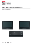
er e. ro /d vr /N ov us /N DR -E B2 1 04 U s e r ’s m a n u a l (short) ht tp :// ww w. e -c am NDR-EB2104 NDR-EB2208 NDR-EB2416 NDR-EB2104 / NDR-EB2208 / NDR-EB2416 User's manual (short) ver. 1.0 04 INFORMACJE IMPORTANT SAFEGUARDS AND WARNINGS B2 1 EMC (2004/108/EC) and LVD (2006/95/EC ) Directives CE Marking DR Electromagnetic compatibility EMC 2004/108/EC. Low voltage LVD 2006/95/EC with further amendment. The Directive applies to electrical equipment designed for use with a voltage rating of between 50VAC and 1000VAC as well as 75VDC and 1500VDC. ov us /N -E Our products are manufactured to comply with requirements of following directives and national regulations implementing the directives: WEEE Directive 2002/96/EC /N Information on Disposal for Users of Waste Electrical and Electronic Equipment er e. ro /d vr This appliance is marked according to the European Directive on Waste Electrical and Electronic Equipment (2002/96/EC) and further amendments. By ensuring this product is disposed of correctly, you will help to prevent potential negative consequences for the environment and human health, which could otherwise be caused by inappropriate waste handling of this product. The symbol on the product, or the documents accompanying the product, indicates that this appliance may not be treated as household waste. It shall be handed over to the applicable collection point for the waste electrical and electronic equipment for recycling purpose. For more information about recycling of this product, please contact your local authorities, your household waste disposal service or the shop where you purchased the product. am RoHS Directive 2002/95/EC ww w. e -c Concerning for human health protection and friendly environment, we assure that our products falling under RoHS Directive regulations, regarding the restriction of the use of hazardous substances in electrical and electronic equipment, were designed and manufactured in compliance with mentioned regulation. Simultaneously, we claim that our products were tested and do not contain hazardous substances exceeding limits which could have negative impact on human health or natural environment. Information ht tp :// The device, as a part of professional CCTV system used for surveillance and control, is not designed for self installation in households by individuals without technical knowledge. The manufacturer is not responsible for defects and damages resulted from improper or inconsistent with user’s manual installation of the device in the system. All rights reserved © AAT Holding sp. z o.o. 2 NDR-EB2104 / NDR-EB2208 / NDR-EB2416 User's manual (short) ver. 1.0 04 SAFETY REQUIREMENTS B2 1 ATTENTION! DR -E PRIOR TO UNDERTAKING ANY ACTION THAT IS NOT PROVISIONED FOR THE GIVEN PRODUCT IN ITS USER’S MANUAL AND OTHER DOCUMENTS DELIVERED WITH THE PRODUCT, OR THAT ARISES FROM THE NORMAL APPLICATION OF THE PRODUCT, ITS MANUFACTURER MUST BE CONTACTED OR THE RESPONSIBILITY OF THE MANUFACTURER FOR THE RESULTS OF SUCH AN ACTION SHELL BE EXCLUDED. ov us /N 1. The installation of NDR-EB2104, NDR-EB2208 and NDR-EB2416 DVRs should be made by a qualified service person or a professional safety system installer. 2. Recorders mustn’t be placed in places where ventilating holes are partially or fully covered. /N 3. User’s interference inside the device is not allowed and is unnecessary as it does not have any systems which require adjusting or which are suitable for self-repair. You mustn’t dismantle the recorder or remove any single fastening screws. If any repairs are necessary contact the service. The device must be take care of and protected against any mechanical damage. /d vr 4. The recorder has to be protected against humidity and dust. In case the recorder had a contact with water react immediately: switch off the power supply and contact the authorised Novus service. If the device gets dirty it might get damaged or electrocute someone. e. ro 5. The device can only be cleaned with a damp cloth after the power supply has been switched off. Avoid strong detergents (liquids and sprays). Mild detergents can be used if the recorder becomes very dirty. am er 6. Power supply unit cords and signal cords should be laid in a way that eliminates the risk of mechanical damage; special attention should be paid to the plug. Be careful not to overload sockets and extension cords so that there is no fire. w. e -c 7. To avoid recorder’s damage vision and control signals should be equipped with systems protecting against disturbances, over voltage and atmospheric discharge that are in compliance with Polish regulations. It is also advised to use ground loop isolators. ww 8. The device mustn’t be used in conditions which do not fulfil operating requirements as far as power supply, relative humidity or air temperature are concerned. 9. You cannot allow any metal objects get inside the recorder. It might cause serious damage. If a metal object gets inside the device contact the authorised Novus service immediately. ht tp :// 10. The manufacturer does not bear responsibility for damage or loss of data stored on HDDs or other media occurred during the usage of the product. All rights reserved © AAT Holding sp. z o.o. 3 NDR-EB2104 / NDR-EB2208 / NDR-EB2416 User's manual (short) ver. 1.0 FOREWORD INFORMATION B2 1 1. 04 FOREWORD INFORMATION 1.1. Main characteristics ww w. e -c am er e. ro /d vr /N ov us /N DR -E PENTAPLEX: simultaneous recording, live monitoring, playback/digital signage, backup and networking Operating system based on Linux Real-time display Recording speed: up to 400 fps H.264 compression Recording resolution: 944 x 576, 944 x 288, 472 x 288, 704 x 576, 704 x 288, 360 x 288 display on two main monitors: Main (HDMI or VGA), Spot (CVBS) Supports up to 2 SATA HDDs* Recording resolution, speed and quality defined individually for each camera Advanced schedule recording & motion detection functions Pre- & post-alarm functions Recording time estimation function Up to 8-channel real-time audio recording External devices support (“Text-in” feature): ATM, POS, AC etc. Digital Signage function Preview on one DVR images from other DVRs connected to the network Advanced search functions of recorded images PTZ control directly from the device or through the network Protocols: N-Control, Pelco-D, Pelco-P and others NV-KBD70, NV-KBD50, NV-KBD30 keyboards compatible Backup: onto HDD or USB Flash Memory through USB port & through the network Networking (simultaneous connections with multiple DVRs and alarm e-mail notification) Software: E-Viewer application for remote administration, live monitoring and recorded data search with a built-in callback module (E-Viewer Callback), iMon2 application for live monitoring, playback receiving information on alarm events, alarm output control, PTZ control, DVR configuration from iPhone and Android OS devices Self-diagnostic functions with automatic notification User friendly multi-lingual OSD Covert camera function IR remote control and PC mouse control (in-set included) Power supply: 12 VDC (100 ~ 240 VAC/12 VDC PSU in-set included) ht tp :// * The list of recommended disk models and their capacity is available on Novus Security website in the Compatible Disk file in the product tab All rights reserved © AAT Holding sp. z o.o. 4 NDR-EB2104 / NDR-EB2208 / NDR-EB2416 User's manual (short) ver. 1.0 04 FOREWORD INFORMATION ht tp :// ww w. e -c am er e. ro /d vr /N ov us /N DR -E B2 1 1.2. NDR-EB2104 / NDR-EB2208 / NDR-EB2416 tech specification: All rights reserved © AAT Holding sp. z o.o. 5 NDR-EB2104 / NDR-EB2208 / NDR-EB2416 User's manual (short) ver. 1.0 STARTING THE DEVICE B2 1 2. 04 STARTING THE DEVICE 2.1. Getting ready to work ov us /N DR -E Unpack the device carefully. After unpacking, please ensure that package contains the following items: Power supply 100~240 VAC/12 VDC vr /N NDR-EB2104 or NDR-EB2208 or NDR-EB2416 IR remote Mouse CD with a full version of user’s manual and software tools and software User’s manual (short) -c Audio cable (only 8 and 16 channel models) am er e. ro /d Power cord ww w. e If any of the elements has been damaged during transport, pack all the elements back into the original packaging and contact your supplier. ht tp :// CAUTION! If the device was brought from a location with lower temperature, please wait until it reaches the temperature of location it is currently in. Turning the device on immediately after bringing it from a location with lower ambient temperature is forbidden, as the condensing water vapour may cause short-circuits and damage the device as a result. Note: Please familiarize yourself with description and functions of rear panel inputs. All rights reserved © AAT Holding sp. z o.o. 6 NDR-EB2104 / NDR-EB2208 / NDR-EB2416 User's manual (short) ver. 1.0 04 STARTING THE DEVICE B2 1 2.2 HDD mounting NDR-EB2104, NDR-EB2208 and NDR-EB2416 support up to two 3,5" SATA HDD. Note: -E vr /N Note: Note: DR Note: In order to obtain info on latest compatible HDDs together with their capacities, please contact your distributor or visit www.novuscctv.com website. AAT HOLDING company does not bear responsibility for any issues arising from usage of unsupported SD cards/HDDs. List of compatible HDDs contains all disks supported by a given DVR model, including desktop HDDs. However due to the fact that image recording prefers reliability usage of 24x7 recording HDDs is therefore advised. If a disk was used in another device, formatting becomes necessary. Please take it into account due to the irrecoverable data loss resulting from said process. All HDD mounted in the DVR should be exactly the same type. Prior to removal of the HDD cover, unplug the power supply first! If DVR is turned on please shut down the system prior to unplugging the device, by selecting SHUTDOWN / LOGOUT. ov us /N Note: /d In order to mount HDD please follow the instructions below: -c am er e. ro Mount the mounting brackets to the HDD (HDDs), like on the picture below: ht tp :// ww w. e Please unscrew the screws as depicted below, then please remove the DVR's cover first by sliding into the rear and then lifting it. All rights reserved © AAT Holding sp. z o.o. 7 NDR-EB2104 / NDR-EB2208 / NDR-EB2416 User's manual (short) ver. 1.0 04 STARTING THE DEVICE /d vr /N ov us /N DR -E B2 1 By default, 2 SATA as well as power cables are connected to the mainboard, ready for connecting HDDs and recorder, as depicted below: ht tp :// ww w. e -c am er e. ro After removing top cover of the DVR, please mount the included HDDs using screws (4 screws for each HDD), next, connect power and signal cables. Below presents a picture of the DVR, with 2 HDDs mounted. After connecting all devices, please put the top cover onto the DVR and turn the device (check chapter 2.6 Plugging in the power) on in order to check the operation of particular components and to format the HDDs. All rights reserved © AAT Holding sp. z o.o. 8 NDR-EB2104 / NDR-EB2208 / NDR-EB2416 User's manual (short) ver. 1.0 1 2 4 5 6 10 8 12 13 14 ov us /N DR 3 NDR-EB2104 view 11 9 -E 7 B2 1 2.3.1 Electrical connection and other back panel elements of the NDR-EB2104 DVR 04 STARTING THE DEVICE VIDEO IN: 4 video inputs for connecting video signal sources to the DVR. Note: When using twisted pair cable counting several hundred meters in length as a transmission medium and with low video signal strength, small crosstalk may appear . 2. AUDIO IN: 3. 4. SPOT: AUDIO OUT: 5. VGA: 6. HDMI: 7. NETWORK: 8. RESET: 9. RS-485: 4 audio mono inputs (RCA LINE IN type) for connecting microphones. Note: Sound recording may be conducted only when legal regulations of a given country allows for such activities. Additional monitor connector, Composite Video Signal (CVBS). Audio output for connecting speakers and amplifier (RCA connector). Connecting the speakers directly to the output is not advised. Main monitor connector, VGA type. The same image (mirror image) appears on HDMI and VGA output. Please use signal cable provided with the monitor when using aforementioned connection type. Main monitor connector, HDMI type. The same image (mirror image) appears on HDMI and VGA output. RJ-45 connector for connecting the DVR to the computer network in 10/100 Mb/s standard. return all DVR settings to original factory default. To reset, firstly turn DVR off, then while holding reset button, turn DVR on. Release the RESET button when system initialize. RS-485 bus connector for connecting external keyboard, PTZ camera or any devices that generate information in the ASCII standard (ATMs, cash registers). The DVR is capable of activating external devices such as buzzers, halide lamps, sirens etc. via its 2 open collector type outputs. Transmitter’s load capacity is 30mA@12VDC. Outputs can be set from the menu as normally open (N.O.) or normally close (N.C.) /d e. ro am er ALARM: -c w. e ww ht tp :// 10. vr /N 1. All rights reserved © AAT Holding sp. z o.o. 9 NDR-EB2104 / NDR-EB2208 / NDR-EB2416 User's manual (short) ver. 1.0 SENSOR: 12. RS-232: 13. 14. DC12V: FAN: 4 alarm inputs, which may be set either as normal open (N.O.) or normal closed (N.C.). Inputs described 1, 2, 3 are standard inputs and can be assigned to the selected DVR function. Input described E can be used only to activate Panic recording. In order to detect the alarm signal it should last at least 0.5sec . The ground of the alarm device needs to be connected to one of the G connectors. Allows to connect external keyboard, PTZ camera or any devices that generate information in the ASCII standard (ATMs, cash registers). Attention: Signal cable used for connecting the RS-232 port is not included in the set. Make sure that the cable used is of DB9S female connector type. Note: Only one of the devices may be connected at a time. Power supply connector ( 100~240 VAC/12VDC PSU in-set included) Cooling fan, do not cover! ov us /N DR -E B2 1 11. 04 STARTING THE DEVICE 8 9 11 15 4 10 12 6 7 3 13 14 VIDEO IN: 2. AUDIO IN 1~8: 5 16 or 8 (depending on the model) video inputs for connecting video signal sources to the DVR. Note: When using twisted pair cable counting several hundred meters in length as a transmission medium and with low video signal strength, small crosstalk may appear . 8 audio mono inputs (RCA LINE IN type on the additional cable in set included) for connecting microphones. Note: Sound recording may be conducted only when legal regulations of a given country allow for such activities. ht tp :// ww w. e -c 1. am NDR-EB2416 view er e. ro /d vr 2 1 /N 2.3.2 Electrical connection and other back panel elements of the NDR-EB2208 and NDR-EB2416 3. 4. SPOT: AUDIO OUT: 5. VGA: Additional monitor connector, Composite Video Signal (CVBS). Audio output for connecting speakers and amplifier (RCA connector). Connecting the speakers directly to the output is not advised. Main monitor connector, VGA type. The same image (mirror image) appears on HDMI and VGA output. Please use signal cable provided with the monitor when using aforementioned connection type. All rights reserved © AAT Holding sp. z o.o. 10 NDR-EB2104 / NDR-EB2208 / NDR-EB2416 User's manual (short) ver. 1.0 04 STARTING THE DEVICE 7. NETWORK: 8. RESET: 9. RS-485: 10. ALARM: 11. SENSOR: 12. RS-232: Main monitor connector, HDMI type. The same image (mirror image) appears on HDMI and VGA output. RJ-45 connector for connecting the DVR to the computer network in 10/100/1000 Mb/s standard. return all DVR settings to original factory default. To reset, firstly turn DVR off, then while holding reset button, turn DVR on. Release the RESET button when system initialize. RS-485 bus connector for connecting external keyboard, PTZ camera or any devices that generate information in the ASCII standard (ATMs, cash registers). The DVR is capable of activating external devices such as buzzers, halide lamps, sirens etc. via its 2 open collector type outputs. Transmitter’s load capacity is 30mA@12VDC. Outputs can be set from the menu as normally open (N.O.) or normally close (N.C.) 4 alarm inputs, which may be set either as normal open (N.O.) or normal closed (N.C.). Inputs described 1, 2, 3 are standard inputs and can be assigned to the selected DVR function. Input described E can be used only to activate Panic recording. In order to detect the alarm signal it should last 0.5sec at least. The ground of the alarm device needs to be connected to one of the G connectors. Allows to connect external keyboard, PTZ camera or any devices that generate information in the ASCII standard (ATMs, cash registers). Attention: Signal cable used for connecting the RS-232 port is not included in the set. Make sure that the cable used is of DB9S female connector type. B2 1 HDMI: e. ro /d vr /N ov us /N DR -E 6. er am DC12V: FAN: E-SATA ht tp :// ww w. e -c 13. 14. 15. Note: Only one of the devices may be connected at a time. Power supply connector ( 100~240 VAC/12VDC PSU in-set included) Cooling fan, do not cover! not available. All rights reserved © AAT Holding sp. z o.o. 11 NDR-EB2104 / NDR-EB2208 / NDR-EB2416 User's manual (short) ver. 1.0 04 STARTING THE DEVICE 2 3 4 6 7 8 9 NDR-EB2416 view 5 /N 10 MENU 4. /d e. ro ht tp :// ww w. e -c 5. er 3. am 2. 11 12 12 Press MENU button to enter recorder’s settings menu (after correct login). Menu functions are detailed in the following chapters of this manual. The button is also used to exit the menu or going to a higher level of the particular submenus. In playback mode and PTZ control mode, MENU button is used for enabling / disabling additional menu functions. PLAYBACK / PRESET Press the PLAYBACK button during “live” mode to enter playback mode. The button is also used to save Presets in the PTZ mode. DISPLAY / Toggles between different display formats. The available formats are: 1, 4, 1 + 5, 9, 1 + 7, 1 + 12, 16, (depending on the model). In the PTZ control mode press the button to call IRIS CLOSE function. BACKUP / Pressing the button allows you to enter the backup menu. In the PTZ control mode press the button to call IRIS OPEN function. Navigation buttons serve a variety of purposes: ► - navigating through the recorder menus and changing the values of each item - choosing another channel or channels in “live” mode - controlling the PTZ cameras - navigating through the zoomed part of the screen in ZOOM mode In the Playback mode navigation buttons are used for: - Press the button to playback images at normal speed. Subsequent ► pressing switches the playback speed between PLAY, FFx2, FFx4, FFx8, FFx16, FFx32. - Press the button to play video backward at regular speed. Pressing the button again switches the playback speed between R.PLAY, RWx2, RWx4, RWx8, RWx16, RWx32. - Press the button to go to the next image. - Press the button to go to the previous image. vr 1. ov us /N DR -E 1 B2 1 2.4. Front panel description All rights reserved © AAT Holding sp. z o.o. 12 NDR-EB2104 / NDR-EB2208 / NDR-EB2416 User's manual (short) ver. 1.0 B2 1 Pressing !E.REC button starts recoding of all camera channels, and displays icon on the main screen. Note: !E.REC function depends of the settings in the RECORD -> Record - > Use Emergency Record ZOOM / MOVE Press the ZOOM button to zoom the current image on the screen. Pressing arrow buttons navigates through the zoomed part of the screen. Function is available only in full screen mode. Press the button to move camera to selected Preset in the PTZ control mode. PTZ / (-) Press the PTZ button to enter the PTZ (Pan/Tilt/Zoom) mode which allows for controlling properly connected PTZ cameras. In the PTZ control mode press the button to call ZOOM OUT function. LOG Press the button to display the system log menu that allows you to view and export the system logs. ENTER / PAUSE Pressing the ENTER button in the setup mode confirms the changes made while in the "live" mode displays additional functions or Login window. In the playback mode press the button to pause the playback screen. LED Flickering green HDD LED indicates that the recording or searching / playback is in progress. Flickering green NETWORK LED means that device is connected to the Ethernet. Solid red ALARM LED light means that the system alarm event occurred (e.g. loss of video signal) and at least one of the alarm outputs or buzzer is active. USB USB 2.0 port for external HDDs, Flash memory or for USB mouse connection. 10. ht tp :// ww w. e -c am er 12. e. ro /d 11. /N 9. vr 8. ov us /N DR 7. ! E.REC -E 6. 04 STARTING THE DEVICE All rights reserved © AAT Holding sp. z o.o. 13 NDR-EB2104 / NDR-EB2208 / NDR-EB2416 User's manual (short) ver. 1.0 04 STARTING THE DEVICE B2 1 2.5. Controlling via IR remote controller /N ov us /N DR -E The set includes an IR remote controller. Its range depends on battery status and may vary between a few and few tens of meters. Single remote may control up to 99 DVRs. If an ID number of the device equals 0, the IR remote control of that device is possible instantly, without any additional setup (furthermore, simultaneous controlling of few DVRs with the same remote is possible). To successfully control a DVR with its ID equal 1~99, please press ID button first. An ID selection menu appears on the DVR screen. Please enter appropriate ID number in the Controller ID field, corresponding to the ID set in the DVR. Confirm by pressing OK. Picture of IR remote together with description of its button functions is presented below: vr NDR-EB2xxx IR remote view Button enabling/disabling emergency recording. Enabling it starts recording all video signals from all channels and displaying the icon on the screen. Recording is realized with parameters defined in the RECORD menu. e. ro /d 1. 1~0 Buttons channel selection buttons: pressing a button displays picture from the camera corresponding to it. Current channel number is displayed in a blue rectangle located at the top right part of the screen. Channel selection buttons are also used for entering digits in the recorder’s OSD. -c am 2. er Note: Operation of this function depends on settings in the RECORD -> Record menu. pressing it while in live view opens the recorder’s menu (after logging in). Menu is then displayed on the screen (its description being presented in later parts of the manual). Additionally, button allows to exit the menu, go a level up or turn the screensaver on. In playback and PTZ control modes the button allows to enable/disable additional menus. DISPLAY ht tp :// 4. ww w. e 3. 5. SEQUENCE toggles between different display formats. selecting displays live channels sequentially. All rights reserved © AAT Holding sp. z o.o. 14 NDR-EB2104 / NDR-EB2208 / NDR-EB2416 User's manual (short) ver. 1.0 04 STARTING THE DEVICE navigation buttons used to: - navigate through recorder’s menu and change parameter values. - selection of successive channels (both in full– and split-screen modes, live and playback view). - control camera in PTZ mode - selects part of the image to be magnified in digital ZOOM mode. DR -E B2 1 6. ov us /N Enter button (in the middle) in OSD menu confirms a selection, while pressing during live view displays additional function menu or login window. opens the recording copy menu. 8. pressing the button in „live” mode switches the recorder into playback mode. 9. in playback mode, button pauses the playback. In PTZ control the button opens the menu that allows to save a preset. 10. pressing the button displays the menu that allows to view and export system logs. 11. pressing the button in playback mode starts playback. Subsequent pressing changes the playback speed by x1, x2, x4, x8, x16 and x32 respectively. Pressing the button in PTZ mode executes IRIS OPEN command. 12. pressing during playback starts playing the recordings backwards. Subsequent presses speeds up the playback consecutively: R.PLAY, x2, x4, x8, x16, x32. In PTZ mode the button decreases zoom factor. 13. in playback mode each button pressing plays the recording forward, frame by frame. Pressing the button in PTZ calls IRIS CLOSE function. -c am er e. ro /d vr /N 7. in playback mode, button plays the recording frame-by-frame back. In PTZ mode the button increases the zoom factor. w. e 14. ht tp :// 16. pressing the button allows to select a PTZ camera (only one that has been already properly set) and open its remote control menu. ww 15. pressing the button in „live” or playback modes allows to enable digital zoom function. Function becomes available only after switching a desired channel into full-screen mode. In order to select a magnified area please use navigation buttons. 17. pressing the button displays menu that allows to enable/disable the PIP function. If enabled, picture from one camera is displayed in a small window superimposed onto a picture originating from a different camera. 18. pressing the button in „live” or playback mode allows to select an audio input (from active), which is then associated with output (built-in speakers) All rights reserved © AAT Holding sp. z o.o. 15 NDR-EB2104 / NDR-EB2208 / NDR-EB2416 User's manual (short) ver. 1.0 04 STARTING THE DEVICE pressing the button in „live” display menu that allows to choose camera displayed on additional (spot) monitor. 20. Consecutive presses cycle between the following OSD display modes: none/ only date, time and camera information/status info bar, as well as hour and date (additionally, a “hide bar” function after a certain period of inactivity is available). 21. pressing the button displays menu that allows to set an ID address of the DVR which is to be controlled. ov us /N DR -E B2 1 19. 2.6. Plugging in the power /N Plugging in the power cable starts recorder operation. Device initialization takes about 30 seconds. Functions shouldn’t be called and buttons pressed during this period. Turning the device off is performed via menu. e. ro /d vr CAUTION! If the device was brought from a location with lower temperature, please wait until it reaches the temperature of location it is currently in. Turning the device on immediately after bringing it from a location with lower ambient temperature is forbidden, as the condensing water vapour may cause short-circuits and damage the device as a result. Note: Please get familiarized with description and functions of rear panel inputs/outputs. am er Reset: : this will return all DVR settings to original factory default. To do reset, turn DVR off first and turn it on again and press and hold reset button until system initialized. (use paper clip or similar to press) -c 2.7. Factory defaults restoring ht tp :// ww w. e In order to restore factory defaults, firstly turn DVR off, then while holding reset button, turn DVR on. Release the RESET button when system initialize. All rights reserved © AAT Holding sp. z o.o. 16 NDR-EB2104 / NDR-EB2208 / NDR-EB2416 User's manual (short) ver. 1.0 DVR MENU B2 1 3. 04 DVR MENU -E NDR-EB2104 / NDR-EB2208 / NDR-EB2416 recorders feature a multilingual OSD menu allowing for adjusting the settings of the device. Available languages are: English, Polish, Korean, Spanish, Slovak, Czech, Turkish, Dutch, Russian, Chinese, Chinese Simplified, Italian, French, Greek, Japanese, German, Finnish, Portuguese and Thai. e. ro /d vr /N ov us /N DR The only difference between 4, 8 and 16- channel versions is in the number of video channels, alarm inputs etc. Prior to using DVR for the first time, initial setup is strongly advised. This includes setting such parameters as time and date, language version, camera, audio, remote control, record mode, network and password. Press the MENU button or select MENU position from additional functions menu (available after pressing the ENTER/PAUSE button) to enter the setup screen. The Login screen, depicted below appears: er Select User and enter the password by pressing the appropriate combination of channel number buttons or using a mouse, then confirm with OK button. am There is no default password when logging in for the first time as the admin user! Please leave the password field void and select OK button. w. e -c Navigate around the menu using arrow buttons as described below: ►- right, - left, - up, - down. ht tp :// ww To confirm your choice, to enter sub-menus and edit value fields use ENTER/PAUSE button. Values may be changed by using the arrow buttons also. To leave setup mode or to leave sub-menus and value editing use MENU button. To set the same value for all fields available in one column highlight the desired column’s name with the cursor and enter the required value. Use the Top Menu to skip to a higher level menu. All rights reserved © AAT Holding sp. z o.o. 17 NDR-EB2104 / NDR-EB2208 / NDR-EB2416 User's manual (short) ver. 1.0 04 OPERATING THE DVR ov us /N DR -E B2 1 A virtual keyboard is available whenever the need for entering names and titles arises. Use the arrow keys to highlight the desired character and press ENTER/PAUSE button. The selected character appears in the title bar and the cursor moves to the next position. Pressing toggles between the upper and lower case letters, serves as the backspace, and DEL deletes entered characters. /N 3.1. LOGOUT/ SHUTDOWN er e. ro /d vr After selecting this submenu the following screen appears: w. e -c am To log out a user please select LOGOUT, and press OK. Additional window prompting for confirmation appears. To confirm, select YES. To turn the DVR off, please select SHUTDOWN and select OK. Additional window prompting for confirmation appears. To confirm, select YES. Second way to shutdown the system is to activate alarm input defined as Shutdown in the EVENT menu. ww To exit the submenu select Cancel. ht tp :// CAUTION! Shutting the system down in any other way than one described here is not allowed as data loss or damage to the device may occur. All rights reserved © AAT Holding sp. z o.o. 18 NDR-EB2104 / NDR-EB2208 / NDR-EB2416 User's manual (short) ver. 1.0 04 OPERATING THE DVR B2 1 4. OPERATING THE DVR DR -E DVR control may be performed via front panel buttons (detailed button description can be found in chapter 2.4 of this manual), USB mouse connected to the DVR as well as remote IR controller. Additionally, the DVR features function menu that can be brought up during „live” view, allowing for calling all the functions assigned to the front panel buttons using only arrow and ENTER buttons. To bring up the menu, please press ENTER or right mouse button. Additional function menu is presented below. ov us /N - name of the user currently logged in - starts display advertise files - selects camera for full screen display /N - equivalent to the OSD on the IR remote - freeze picture vr - contains Sequence, Zoom, PIP, Spot monitor functions /d - equivalent to the AUDIO on the IR remote e. ro - equivalent to the PTZ on the IR remote - equivalent to the BACKUP on the IR remote - displays image form the other DVR via network - equivalent to the ! E.REC on the IR remote - equivalent to the LOG on the IR remote - enters the main menu of the DVR ht tp :// ww w. e -c am er - equivalent to the PLAYBACK on the IR remote Widok dla NV-DVR1600 All rights reserved © AAT Holding sp. z o.o. 19 NDR-EB2104 / NDR-EB2208 / NDR-EB2416 User's manual (short) ver. 1.0 04 OPERATING THE DVR B2 1 4.1. Live monitoring -E As soon as the DVR completes its initialization process, it starts displaying live video via the connected monitor. ov us /N DR Displaying all cameras simultaneously is the default mode (4, 8 or 16 depending on the model). Press a camera button to display this particular camera full screen. Pressing DISPLAY button cycles through different display modes. If images from 4 cameras are displayed simultaneously on the monitor use Left, Right, Up or Down arrow buttons to switch between displayed cameras according to the following scheme: /N Other view modes utilize similar way of switching between cameras. In 5+1, 7+1 or 12+1 display modes, camera 1 is always displayed in the middle. e. ro /d vr Press SEQUENCE button to enable full-screen or multi-camera sequence display. Any change of the display mode or subsequent SEQUENCE button pressing turns off the sequential display. Full screen display sequence skips past the channels without video signal connected. Sequence switching time can be set in the DVR menu. Duration of sequence display is defined in the menu. Press FREEZE button to freeze/unfreeze the currently displayed image. ht tp :// ww w. e -c am er Press SPOT button to set the camera displayed on additional monitor (CVBS connector). It could be single camera or sequence. All rights reserved © AAT Holding sp. z o.o. 20 NDR-EB2104 / NDR-EB2208 / NDR-EB2416 User's manual (short) ver. 1.0 04 OPERATING THE DVR B2 1 4.2. Playing recorded video -E Users, that have the privileges to watch stored recordings, after logging in to the DVR may do so. To start the playback, please press the PLAYBACK button. If the stored material is viewed for the first time since the device power-up, latest recordings will be shown. DR Note: Pictures from cameras set as covert are visible during playback. /N ov us /N - press the button to play video backward at normal speed. Press the button again to change playback speed. The screen displays R.PLAY, RWx2, RWx4, RWx8, RWx16 and RWx32 respectively. ► - press the button to play video forward at normal speed. Press the button again to change playback speed. The screen displays PLAY, FFx2, FFx4, FFx8, FFx16 and FFx32 respectively. - press the button to go to the next image (frame by frame forward). - press the button to go to the previous image (frame by frame backward). - press the button to pause the playback. /d vr Playback display mode change is performed exactly as in "live" mode, so does digital zoom function. Press the MENU button during playback to display additional menu that allows to exit the playback mode and enable /disable additional functions. The additional menu is shown below. e. ro - information on currently logged-in user - full screen display camera selection - goes to the beginning/end or defined date of the recordings er - calendar records search ht tp :// ww w. e -c am - event records search - text in records search - equivalent to the OSD button on the IR remote - equivalent to the ZOOM button on the IR remote - enables/disables audio playback - equivalent to the BACKUP button on the IR remote - playback storage selection HDD/Backup Data - equivalent to the ! E.REC button on the IR remote - equivalent to the LOG button on the IR remote - exits the playback mode All rights reserved © AAT Holding sp. z o.o. 21 NDR-EB2104 / NDR-EB2208 / NDR-EB2416 User's manual (short) ver. 1.0 04 OPERATING THE DVR B2 1 4.3. Playing backup material ov us /N DR -E Recorders feature the function of playing back previously stored recordings. Only *. STRG format recordings are recognized by the system during playback, without the player compiled. Playback feature is enabled only if an external memory is connected. In order to start playback call additional function menu in "live" mode by pressing ENTER button. Then, select Playback position and Backup Data. A screen should appear, allowing you to select desired storage device and recording from available. Use the navigation keys to select the desired file, and then choose ENTER button to confirm. The methods of Backup video control are the same as in Recorded video playback. 4.4. Searching video Go to Beginning - go to the beginning of recordings; Go to End - go to the end of recordings; Go to time - search by the date and time, or go to the beginning / end of recordings; er e. ro /d vr /N Press the MENU/EXIT in the playback mode to start searching display menu. After selecting Go to position, the following window is opened: w. e Calendar Search - searching the recordings with calendar use; Event Search - searching the recordings events associated with; Text-In Search - searching the recordings defined text associated with; ww -c am Below positions from additional menu are used for: ht tp :// Note: When DVR is in playback mode the network transmission speed may decrease as a result. During the recording playback/search there is a possibility of slight recording speed decrease. All rights reserved © AAT Holding sp. z o.o. 22 NDR-EB2104 / NDR-EB2208 / NDR-EB2416 User's manual (short) ver. 1.0 04 OPERATING THE DVR B2 1 4.5. Backup DR -E NDR-EB2104/NDR-EB2208 and NDR-EB2416 digital multiplexers provide a wide branch of methods when it comes to copying the recordings. User may copy recordings to external storage devices. The DVR features the possibility of copying the recordings to an external HDD connected via the USB, or to copy the data onto Flash memories. DVRs allow to copy the recordings in three available formats. Data format determines its later playback and maximum file size. Following formats are available: File size may not exceed 4 GB, both for FAT32 and NTFS. Number of channels that are copied in the process is not restricted. The stored data may be played back on the PC with Windows OS without installing additional software. Note: When copying *.exe files, FAT32 file system is recommended on the storage device. Using NTFS-formatted storage device and exceeding maximum file size for that system (4GB) will result in inability to playback the copied recordings as the copy process won’t stop after exceeding max. file size. /N ov us /N *.exe - *.strg - Only FAT32 or NTFS file systems are supported on the storage devices. When copying *.mp4 recordings maximum file size should not exceed 2GB. am Note: Note: er e. ro /d vr Data are copied to *.strg format. File size may not exceed 4 GB for FAT 32 file system. In case of NTFS file system, maximum file size is limited only to the NTFS maximum file size. Maximum number of channels is also unrestricted. Data stored in this format may be played back on PCs with E-Viewer installed, or by DVR. *.mp4 - Data are copied to *.mp4 format. File size may not exceed 2 GB, both for FAT32 and NTFS. Only one video channel is permitted during copy process. Recordings may be played back on PCs with mp4-capable software installed. w. e -c Detailed information about configuration, service and installation of recorders available in full version of user's manual located on the attached CD-ROM and on the www.novuscctv.com website ht tp :// ww Note: Manufacturer reserves the right for updating technical parameters and documentation without prior notification. Printing errors possible. All rights reserved © AAT Holding sp. z o.o. 23 NDR-EB2104 / NDR-EB2208 / NDR-EB2416 User's manual (short) ver. 1.0 ht tp :// ww w. e -c am er e. ro /d vr /N ov us /N DR -E B2 1 04 NOTES All rights reserved © AAT Holding sp. z o.o. 24