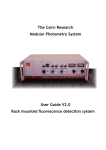
1
R&S®SGS100A SGMA RF Source User Manual (;×é52) User Manual Test & Measurement 1173.9105.02 ─ 03 This document describes the R&S®SGS100A, stock no. 1416.0505.02 and its options. The firmware of the instrument makes use of the operating system LINUX® and other valuable open source software packages. The most important of them together with their corresponding open source license and the verbatim license texts are provided on the user documentation CD-ROM (included in delivery). The OpenSSL Project for use in the OpenSSL Toolkit (http://www.openssl.org/) includes cryptographic software written by Eric Young ([email protected]) and software written by Tim Hudson ([email protected]). LINUX® is a trademark of Linus Torvalds. Rohde & Schwarz would like to thank the open source community for their valuable contribution to embedded computing. © 2011 Rohde & Schwarz GmbH & Co. KG Muehldorfstr. 15, 81671 Munich, Germany Phone: +49 89 41 29 - 0 Fax: +49 89 41 29 12 164 E-mail: [email protected] Internet: http://www.rohde-schwarz.com Printed in Germany – Subject to change – Data without tolerance limits is not binding. R&S® is a registered trademark of Rohde & Schwarz GmbH & Co. KG. Trade names are trademarks of the owners. The following abbreviations are used throughout this manual: R&S®SGS100A is abbreviated as R&S SGS, R&S®SGMA-GUI is abbreviated as R&S SGMA-GUI, R&S®FSV is abbreviated as R&S FSV, R&S®AFQ100B is abbreviated as R&S AFQ100B, R&S®SMU200A is abbreviated as R&S SMU. Basic Safety Instructions Always read through and comply with the following safety instructions! All plants and locations of the Rohde & Schwarz group of companies make every effort to keep the safety standards of our products up to date and to offer our customers the highest possible degree of safety. Our products and the auxiliary equipment they require are designed, built and tested in accordance with the safety standards that apply in each case. Compliance with these standards is continuously monitored by our quality assurance system. The product described here has been designed, built and tested in accordance with the attached EC Certificate of Conformity and has left the manufacturer’s plant in a condition fully complying with safety standards. To maintain this condition and to ensure safe operation, you must observe all instructions and warnings provided in this manual. If you have any questions regarding these safety instructions, the Rohde & Schwarz group of companies will be happy to answer them. Furthermore, it is your responsibility to use the product in an appropriate manner. This product is designed for use solely in industrial and laboratory environments or, if expressly permitted, also in the field and must not be used in any way that may cause personal injury or property damage. You are responsible if the product is used for any intention other than its designated purpose or in disregard of the manufacturer's instructions. The manufacturer shall assume no responsibility for such use of the product. The product is used for its designated purpose if it is used in accordance with its product documentation and within its performance limits (see data sheet, documentation, the following safety instructions). Using the product requires technical skills and a basic knowledge of English. It is therefore essential that only skilled and specialized staff or thoroughly trained personnel with the required skills be allowed to use the product. If personal safety gear is required for using Rohde & Schwarz products, this will be indicated at the appropriate place in the product documentation. Keep the basic safety instructions and the product documentation in a safe place and pass them on to the subsequent users. Observing the safety instructions will help prevent personal injury or damage of any kind caused by dangerous situations. Therefore, carefully read through and adhere to the following safety instructions before and when using the product. It is also absolutely essential to observe the additional safety instructions on personal safety, for example, that appear in relevant parts of the product documentation. In these safety instructions, the word "product" refers to all merchandise sold and distributed by the Rohde & Schwarz group of companies, including instruments, systems and all accessories. Symbols and safety labels Notice, general danger location Observe product documentation ON/OFF supply voltage Caution when handling heavy equipment Standby indication 1171.0000.42-05.00 Danger of electric shock Direct current (DC) Warning! Hot surface PE terminal Alternating current (AC) Ground Direct/alternating current (DC/AC) Ground terminal Be careful when handling electrostatic sensitive devices Device fully protected by double (reinforced) insulation Page 1 Basic Safety Instructions Tags and their meaning The following signal words are used in the product documentation in order to warn the reader about risks and dangers. indicates a hazardous situation which, if not avoided, will result in death or serious injury. indicates a hazardous situation which, if not avoided, could result in death or serious injury. indicates a hazardous situation which, if not avoided, could result in minor or moderate injury. indicates the possibility of incorrect operation which can result in damage to the product. In the product documentation, the word ATTENTION is used synonymously. These tags are in accordance with the standard definition for civil applications in the European Economic Area. Definitions that deviate from the standard definition may also exist in other economic areas or military applications. It is therefore essential to make sure that the tags described here are always used only in connection with the related product documentation and the related product. The use of tags in connection with unrelated products or documentation can result in misinterpretation and in personal injury or material damage. Operating states and operating positions The product may be operated only under the operating conditions and in the positions specified by the manufacturer, without the product's ventilation being obstructed. If the manufacturer's specifications are not observed, this can result in electric shock, fire and/or serious personal injury or death. Applicable local or national safety regulations and rules for the prevention of accidents must be observed in all work performed. 1. Unless otherwise specified, the following requirements apply to Rohde & Schwarz products: predefined operating position is always with the housing floor facing down, IP protection 2X, pollution severity 2, overvoltage category 2, use only indoors, max. operating altitude 2000 m above sea level, max. transport altitude 4500 m above sea level. A tolerance of ±10 % shall apply to the nominal voltage and ±5 % to the nominal frequency. 2. Do not place the product on surfaces, vehicles, cabinets or tables that for reasons of weight or stability are unsuitable for this purpose. Always follow the manufacturer's installation instructions when installing the product and fastening it to objects or structures (e.g. walls and shelves). An installation that is not carried out as described in the product documentation could result in personal injury or death. 3. Do not place the product on heat-generating devices such as radiators or fan heaters. The ambient temperature must not exceed the maximum temperature specified in the product documentation or in the data sheet. Product overheating can cause electric shock, fire and/or serious personal injury or death. 1171.0000.42-05.00 Page 2 Basic Safety Instructions Electrical safety If the information on electrical safety is not observed either at all to the extent necessary, electric shock, fire and/or serious personal injury or death may occur. 1. Prior to switching on the product, always ensure that the nominal voltage setting on the product matches the nominal voltage of the AC supply network. If a different voltage is to be set, the power fuse of the product may have to be changed accordingly. 2. In the case of products of safety class I with movable power cord and connector, operation is permitted only on sockets with an earthing contact and protective earth connection. 3. Intentionally breaking the protective earth connection either in the feed line or in the product itself is not permitted. Doing so can result in the danger of an electric shock from the product. If extension cords or connector strips are implemented, they must be checked on a regular basis to ensure that they are safe to use. 4. If the product does not have a power switch for disconnection from the AC supply network, the plug of the connecting cable is regarded as the disconnecting device. In such cases, always ensure that the power plug is easily reachable and accessible at all times (corresponding to the length of connecting cable, approx. 2 m). Functional or electronic switches are not suitable for providing disconnection from the AC supply network. If products without power switches are integrated into racks or systems, a disconnecting device must be provided at the system level. 5. Never use the product if the power cable is damaged. Check the power cable on a regular basis to ensure that it is in proper operating condition. By taking appropriate safety measures and carefully laying the power cable, you can ensure that the cable will not be damaged and that no one can be hurt by, for example, tripping over the cable or suffering an electric shock. 6. The product may be operated only from TN/TT supply networks fused with max. 16 A (higher fuse only after consulting with the Rohde & Schwarz group of companies). 7. Do not insert the plug into sockets that are dusty or dirty. Insert the plug firmly and all the way into the socket. Otherwise, sparks that result in fire and/or injuries may occur. 8. Do not overload any sockets, extension cords or connector strips; doing so can cause fire or electric shocks. 9. For measurements in circuits with voltages Vrms > 30 V, suitable measures (e.g. appropriate measuring equipment, fusing, current limiting, electrical separation, insulation) should be taken to avoid any hazards. 10. Ensure that the connections with information technology equipment, e.g. PCs or other industrial computers, comply with the IEC60950-1/EN60950-1 or IEC61010-1/EN 61010-1 standards that apply in each case. 11. Unless expressly permitted, never remove the cover or any part of the housing while the product is in operation. Doing so will expose circuits and components and can lead to injuries, fire or damage to the product. 12. If a product is to be permanently installed, the connection between the PE terminal on site and the product's PE conductor must be made first before any other connection is made. The product may be installed and connected only by a licensed electrician. 13. For permanently installed equipment without built-in fuses, circuit breakers or similar protective devices, the supply circuit must be fused in such a way that anyone who has access to the product, as well as the product itself, is adequately protected from injury or damage. 1171.0000.42-05.00 Page 3 Basic Safety Instructions 14. Use suitable overvoltage protection to ensure that no overvoltage (such as that caused by a bolt of lightning) can reach the product. Otherwise, the person operating the product will be exposed to the danger of an electric shock. 15. Any object that is not designed to be placed in the openings of the housing must not be used for this purpose. Doing so can cause short circuits inside the product and/or electric shocks, fire or injuries. 16. Unless specified otherwise, products are not liquid-proof (see also section "Operating states and operating positions", item 1. Therefore, the equipment must be protected against penetration by liquids. If the necessary precautions are not taken, the user may suffer electric shock or the product itself may be damaged, which can also lead to personal injury. 17. Never use the product under conditions in which condensation has formed or can form in or on the product, e.g. if the product has been moved from a cold to a warm environment. Penetration by water increases the risk of electric shock. 18. Prior to cleaning the product, disconnect it completely from the power supply (e.g. AC supply network or battery). Use a soft, non-linting cloth to clean the product. Never use chemical cleaning agents such as alcohol, acetone or diluents for cellulose lacquers. Operation 1. Operating the products requires special training and intense concentration. Make sure that persons who use the products are physically, mentally and emotionally fit enough to do so; otherwise, injuries or material damage may occur. It is the responsibility of the employer/operator to select suitable personnel for operating the products. 2. Before you move or transport the product, read and observe the section titled "Transport". 3. As with all industrially manufactured goods, the use of substances that induce an allergic reaction (allergens) such as nickel cannot be generally excluded. If you develop an allergic reaction (such as a skin rash, frequent sneezing, red eyes or respiratory difficulties) when using a Rohde & Schwarz product, consult a physician immediately to determine the cause and to prevent health problems or stress. 4. Before you start processing the product mechanically and/or thermally, or before you take it apart, be sure to read and pay special attention to the section titled "Waste disposal", item 1. 5. Depending on the function, certain products such as RF radio equipment can produce an elevated level of electromagnetic radiation. Considering that unborn babies require increased protection, pregnant women must be protected by appropriate measures. Persons with pacemakers may also be exposed to risks from electromagnetic radiation. The employer/operator must evaluate workplaces where there is a special risk of exposure to radiation and, if necessary, take measures to avert the potential danger. 6. Should a fire occur, the product may release hazardous substances (gases, fluids, etc.) that can cause health problems. Therefore, suitable measures must be taken, e.g. protective masks and protective clothing must be worn. 7. If a laser product (e.g. a CD/DVD drive) is integrated into a Rohde & Schwarz product, absolutely no other settings or functions may be used as described in the product documentation. The objective is to prevent personal injury (e.g. due to laser beams). 1171.0000.42-05.00 Page 4 Basic Safety Instructions Repair and service 1. The product may be opened only by authorized, specially trained personnel. Before any work is performed on the product or before the product is opened, it must be disconnected from the AC supply network. Otherwise, personnel will be exposed to the risk of an electric shock. 2. Adjustments, replacement of parts, maintenance and repair may be performed only by electrical experts authorized by Rohde & Schwarz. Only original parts may be used for replacing parts relevant to safety (e.g. power switches, power transformers, fuses). A safety test must always be performed after parts relevant to safety have been replaced (visual inspection, PE conductor test, insulation resistance measurement, leakage current measurement, functional test). This helps ensure the continued safety of the product. Batteries and rechargeable batteries/cells If the information regarding batteries and rechargeable batteries/cells is not observed either at all or to the extent necessary, product users may be exposed to the risk of explosions, fire and/or serious personal injury, and, in some cases, death. Batteries and rechargeable batteries with alkaline electrolytes (e.g. lithium cells) must be handled in accordance with the EN 62133 standard. 1. Cells must not be taken apart or crushed. 2. Cells or batteries must not be exposed to heat or fire. Storage in direct sunlight must be avoided. Keep cells and batteries clean and dry. Clean soiled connectors using a dry, clean cloth. 3. Cells or batteries must not be short-circuited. Cells or batteries must not be stored in a box or in a drawer where they can short-circuit each other, or where they can be short-circuited by other conductive materials. Cells and batteries must not be removed from their original packaging until they are ready to be used. 4. Keep cells and batteries out of the hands of children. If a cell or a battery has been swallowed, seek medical aid immediately. 5. Cells and batteries must not be exposed to any mechanical shocks that are stronger than permitted. 6. If a cell develops a leak, the fluid must not be allowed to come into contact with the skin or eyes. If contact occurs, wash the affected area with plenty of water and seek medical aid. 7. Improperly replacing or charging cells or batteries that contain alkaline electrolytes (e.g. lithium cells) can cause explosions. Replace cells or batteries only with the matching Rohde & Schwarz type (see parts list) in order to ensure the safety of the product. 8. Cells and batteries must be recycled and kept separate from residual waste. Rechargeable batteries and normal batteries that contain lead, mercury or cadmium are hazardous waste. Observe the national regulations regarding waste disposal and recycling. Transport 1. The product may be very heavy. Therefore, the product must be handled with care. In some cases, the user may require a suitable means of lifting or moving the product (e.g. with a lift-truck) to avoid back or other physical injuries. 1171.0000.42-05.00 Page 5 Informaciones elementales de seguridad 2. Handles on the products are designed exclusively to enable personnel to transport the product. It is therefore not permissible to use handles to fasten the product to or on transport equipment such as cranes, fork lifts, wagons, etc. The user is responsible for securely fastening the products to or on the means of transport or lifting. Observe the safety regulations of the manufacturer of the means of transport or lifting. Noncompliance can result in personal injury or material damage. 3. If you use the product in a vehicle, it is the sole responsibility of the driver to drive the vehicle safely and properly. The manufacturer assumes no responsibility for accidents or collisions. Never use the product in a moving vehicle if doing so could distract the driver of the vehicle. Adequately secure the product in the vehicle to prevent injuries or other damage in the event of an accident. Waste disposal 1. If products or their components are mechanically and/or thermally processed in a manner that goes beyond their intended use, hazardous substances (heavy-metal dust such as lead, beryllium, nickel) may be released. For this reason, the product may only be disassembled by specially trained personnel. Improper disassembly may be hazardous to your health. National waste disposal regulations must be observed. 2. If handling the product releases hazardous substances or fuels that must be disposed of in a special way, e.g. coolants or engine oils that must be replenished regularly, the safety instructions of the manufacturer of the hazardous substances or fuels and the applicable regional waste disposal regulations must be observed. Also observe the relevant safety instructions in the product documentation. The improper disposal of hazardous substances or fuels can cause health problems and lead to environmental damage. Informaciones elementales de seguridad Es imprescindible leer y observar las siguientes instrucciones e informaciones de seguridad! El principio del grupo de empresas Rohde & Schwarz consiste en tener nuestros productos siempre al día con los estándares de seguridad y de ofrecer a nuestros clientes el máximo grado de seguridad. Nuestros productos y todos los equipos adicionales son siempre fabricados y examinados según las normas de seguridad vigentes. Nuestro sistema de garantía de calidad controla constantemente que sean cumplidas estas normas. El presente producto ha sido fabricado y examinado según el certificado de conformidad adjunto de la UE y ha salido de nuestra planta en estado impecable según los estándares técnicos de seguridad. Para poder preservar este estado y garantizar un funcionamiento libre de peligros, el usuario deberá atenerse a todas las indicaciones, informaciones de seguridad y notas de alerta. El grupo de empresas Rohde & Schwarz está siempre a su disposición en caso de que tengan preguntas referentes a estas informaciones de seguridad. Además queda en la responsabilidad del usuario utilizar el producto en la forma debida. Este producto está destinado exclusivamente al uso en la industria y el laboratorio o, si ha sido expresamente autorizado, para aplicaciones de campo y de ninguna manera deberá ser utilizado de modo que alguna persona/cosa pueda sufrir daño. El uso del producto fuera de sus fines definidos o sin tener en cuenta las instrucciones del fabricante queda en la responsabilidad del usuario. El fabricante no se hace en ninguna forma responsable de consecuencias a causa del mal uso del producto. 1171.0000.42-05.00 Page 6 Informaciones elementales de seguridad Se parte del uso correcto del producto para los fines definidos si el producto es utilizado conforme a las indicaciones de la correspondiente documentación del producto y dentro del margen de rendimiento definido (ver hoja de datos, documentación, informaciones de seguridad que siguen). El uso del producto hace necesarios conocimientos técnicos y ciertos conocimientos del idioma inglés. Por eso se debe tener en cuenta que el producto solo pueda ser operado por personal especializado o personas instruidas en profundidad con las capacidades correspondientes. Si fuera necesaria indumentaria de seguridad para el uso de productos de Rohde & Schwarz, encontraría la información debida en la documentación del producto en el capítulo correspondiente. Guarde bien las informaciones de seguridad elementales, así como la documentación del producto, y entréguelas a usuarios posteriores. Tener en cuenta las informaciones de seguridad sirve para evitar en lo posible lesiones o daños por peligros de toda clase. Por eso es imprescindible leer detalladamente y comprender por completo las siguientes informaciones de seguridad antes de usar el producto, y respetarlas durante el uso del producto. Deberán tenerse en cuenta todas las demás informaciones de seguridad, como p. ej. las referentes a la protección de personas, que encontrarán en el capítulo correspondiente de la documentación del producto y que también son de obligado cumplimiento. En las presentes informaciones de seguridad se recogen todos los objetos que distribuye el grupo de empresas Rohde & Schwarz bajo la denominación de "producto", entre ellos también aparatos, instalaciones así como toda clase de accesorios. Símbolos y definiciones de seguridad Aviso: punto de peligro general Observar la documentación del producto Tensión de alimentación de PUESTA EN MARCHA / PARADA Atención en el manejo de dispositivos de peso elevado Indicación de estado de espera (Standby) 1171.0000.42-05.00 Peligro de choque eléctrico Advertencia: superficie caliente Corriente continua (DC) Conexión a conductor de protección Corriente alterna (AC) Conexión a tierra Conexión a masa Corriente continua / Corriente alterna (DC/AC) Aviso: Cuidado en el manejo de dispositivos sensibles a la electrostática (ESD) El aparato está protegido en su totalidad por un aislamiento doble (reforzado) Page 7 Informaciones elementales de seguridad Palabras de señal y su significado En la documentación del producto se utilizan las siguientes palabras de señal con el fin de advertir contra riesgos y peligros. PELIGRO identifica un peligro inminente con riesgo elevado que provocará muerte o lesiones graves si no se evita. ADVERTENCIA identifica un posible peligro con riesgo medio de provocar muerte o lesiones (graves) si no se evita. ATENCIÓN identifica un peligro con riesgo reducido de provocar lesiones leves o moderadas si no se evita. AVISO indica la posibilidad de utilizar mal el producto y, como consecuencia, dañarlo. En la documentación del producto se emplea de forma sinónima el término CUIDADO. Las palabras de señal corresponden a la definición habitual para aplicaciones civiles en el área económica europea. Pueden existir definiciones diferentes a esta definición en otras áreas económicas o en aplicaciones militares. Por eso se deberá tener en cuenta que las palabras de señal aquí descritas sean utilizadas siempre solamente en combinación con la correspondiente documentación del producto y solamente en combinación con el producto correspondiente. La utilización de las palabras de señal en combinación con productos o documentaciones que no les correspondan puede llevar a interpretaciones equivocadas y tener por consecuencia daños en personas u objetos. Estados operativos y posiciones de funcionamiento El producto solamente debe ser utilizado según lo indicado por el fabricante respecto a los estados operativos y posiciones de funcionamiento sin que se obstruya la ventilación. Si no se siguen las indicaciones del fabricante, pueden producirse choques eléctricos, incendios y/o lesiones graves con posible consecuencia de muerte. En todos los trabajos deberán ser tenidas en cuenta las normas nacionales y locales de seguridad del trabajo y de prevención de accidentes. 1. Si no se convino de otra manera, es para los productos Rohde & Schwarz válido lo que sigue: como posición de funcionamiento se define por principio la posición con el suelo de la caja para abajo, modo de protección IP 2X, grado de suciedad 2, categoría de sobrecarga eléctrica 2, uso solamente en estancias interiores, utilización hasta 2000 m sobre el nivel del mar, transporte hasta 4500 m sobre el nivel del mar. Se aplicará una tolerancia de ±10 % sobre el voltaje nominal y de ±5 % sobre la frecuencia nominal. 2. No sitúe el producto encima de superficies, vehículos, estantes o mesas, que por sus características de peso o de estabilidad no sean aptos para él. Siga siempre las instrucciones de instalación del fabricante cuando instale y asegure el producto en objetos o estructuras (p. ej. paredes y estantes). Si se realiza la instalación de modo distinto al indicado en la documentación del producto, pueden causarse lesiones o incluso la muerte. 3. No ponga el producto sobre aparatos que generen calor (p. ej. radiadores o calefactores). La temperatura ambiente no debe superar la temperatura máxima especificada en la documentación del producto o en la hoja de datos. En caso de sobrecalentamiento del producto, pueden producirse choques eléctricos, incendios y/o lesiones graves con posible consecuencia de muerte. 1171.0000.42-05.00 Page 8 Informaciones elementales de seguridad Seguridad eléctrica Si no se siguen (o se siguen de modo insuficiente) las indicaciones del fabricante en cuanto a seguridad eléctrica, pueden producirse choques eléctricos, incendios y/o lesiones graves con posible consecuencia de muerte. 1. Antes de la puesta en marcha del producto se deberá comprobar siempre que la tensión preseleccionada en el producto coincida con la de la red de alimentación eléctrica. Si es necesario modificar el ajuste de tensión, también se deberán cambiar en caso dado los fusibles correspondientes del producto. 2. Los productos de la clase de protección I con alimentación móvil y enchufe individual solamente podrán enchufarse a tomas de corriente con contacto de seguridad y con conductor de protección conectado. 3. Queda prohibida la interrupción intencionada del conductor de protección, tanto en la toma de corriente como en el mismo producto. La interrupción puede tener como consecuencia el riesgo de que el producto sea fuente de choques eléctricos. Si se utilizan cables alargadores o regletas de enchufe, deberá garantizarse la realización de un examen regular de los mismos en cuanto a su estado técnico de seguridad. 4. Si el producto no está equipado con un interruptor para desconectarlo de la red, se deberá considerar el enchufe del cable de conexión como interruptor. En estos casos se deberá asegurar que el enchufe siempre sea de fácil acceso (de acuerdo con la longitud del cable de conexión, aproximadamente 2 m). Los interruptores de función o electrónicos no son aptos para el corte de la red eléctrica. Si los productos sin interruptor están integrados en bastidores o instalaciones, se deberá colocar el interruptor en el nivel de la instalación. 5. No utilice nunca el producto si está dañado el cable de conexión a red. Compruebe regularmente el correcto estado de los cables de conexión a red. Asegúrese, mediante las medidas de protección y de instalación adecuadas, de que el cable de conexión a red no pueda ser dañado o de que nadie pueda ser dañado por él, p. ej. al tropezar o por un choque eléctrico. 6. Solamente está permitido el funcionamiento en redes de alimentación TN/TT aseguradas con fusibles de 16 A como máximo (utilización de fusibles de mayor amperaje solo previa consulta con el grupo de empresas Rohde & Schwarz). 7. Nunca conecte el enchufe en tomas de corriente sucias o llenas de polvo. Introduzca el enchufe por completo y fuertemente en la toma de corriente. La no observación de estas medidas puede provocar chispas, fuego y/o lesiones. 8. No sobrecargue las tomas de corriente, los cables alargadores o las regletas de enchufe ya que esto podría causar fuego o choques eléctricos. 9. En las mediciones en circuitos de corriente con una tensión Ueff > 30 V se deberán tomar las medidas apropiadas para impedir cualquier peligro (p. ej. medios de medición adecuados, seguros, limitación de tensión, corte protector, aislamiento etc.). 10. Para la conexión con dispositivos informáticos como un PC o un ordenador industrial, debe comprobarse que éstos cumplan los estándares IEC60950-1/EN60950-1 o IEC61010-1/EN 61010-1 válidos en cada caso. 11. A menos que esté permitido expresamente, no retire nunca la tapa ni componentes de la carcasa mientras el producto esté en servicio. Esto pone a descubierto los cables y componentes eléctricos y puede causar lesiones, fuego o daños en el producto. 1171.0000.42-05.00 Page 9 Informaciones elementales de seguridad 12. Si un producto se instala en un lugar fijo, se deberá primero conectar el conductor de protección fijo con el conductor de protección del producto antes de hacer cualquier otra conexión. La instalación y la conexión deberán ser efectuadas por un electricista especializado. 13. En el caso de dispositivos fijos que no estén provistos de fusibles, interruptor automático ni otros mecanismos de seguridad similares, el circuito de alimentación debe estar protegido de modo que todas las personas que puedan acceder al producto, así como el producto mismo, estén a salvo de posibles daños. 14. Todo producto debe estar protegido contra sobretensión (debida p. ej. a una caída del rayo) mediante los correspondientes sistemas de protección. Si no, el personal que lo utilice quedará expuesto al peligro de choque eléctrico. 15. No debe introducirse en los orificios de la caja del aparato ningún objeto que no esté destinado a ello. Esto puede producir cortocircuitos en el producto y/o puede causar choques eléctricos, fuego o lesiones. 16. Salvo indicación contraria, los productos no están impermeabilizados (ver también el capítulo "Estados operativos y posiciones de funcionamiento", punto 1). Por eso es necesario tomar las medidas necesarias para evitar la entrada de líquidos. En caso contrario, existe peligro de choque eléctrico para el usuario o de daños en el producto, que también pueden redundar en peligro para las personas. 17. No utilice el producto en condiciones en las que pueda producirse o ya se hayan producido condensaciones sobre el producto o en el interior de éste, como p. ej. al desplazarlo de un lugar frío a otro caliente. La entrada de agua aumenta el riesgo de choque eléctrico. 18. Antes de la limpieza, desconecte por completo el producto de la alimentación de tensión (p. ej. red de alimentación o batería). Realice la limpieza de los aparatos con un paño suave, que no se deshilache. No utilice bajo ningún concepto productos de limpieza químicos como alcohol, acetona o diluyentes para lacas nitrocelulósicas. Funcionamiento 1. El uso del producto requiere instrucciones especiales y una alta concentración durante el manejo. Debe asegurarse que las personas que manejen el producto estén a la altura de los requerimientos necesarios en cuanto a aptitudes físicas, psíquicas y emocionales, ya que de otra manera no se pueden excluir lesiones o daños de objetos. El empresario u operador es responsable de seleccionar el personal usuario apto para el manejo del producto. 2. Antes de desplazar o transportar el producto, lea y tenga en cuenta el capítulo "Transporte". 3. Como con todo producto de fabricación industrial no puede quedar excluida en general la posibilidad de que se produzcan alergias provocadas por algunos materiales empleados, los llamados alérgenos (p. ej. el níquel). Si durante el manejo de productos Rohde & Schwarz se producen reacciones alérgicas, como p. ej. irritaciones cutáneas, estornudos continuos, enrojecimiento de la conjuntiva o dificultades respiratorias, debe avisarse inmediatamente a un médico para investigar las causas y evitar cualquier molestia o daño a la salud. 4. Antes de la manipulación mecánica y/o térmica o el desmontaje del producto, debe tenerse en cuenta imprescindiblemente el capítulo "Eliminación", punto 1. 1171.0000.42-05.00 Page 10 Informaciones elementales de seguridad 5. Ciertos productos, como p. ej. las instalaciones de radiocomunicación RF, pueden a causa de su función natural, emitir una radiación electromagnética aumentada. Deben tomarse todas las medidas necesarias para la protección de las mujeres embarazadas. También las personas con marcapasos pueden correr peligro a causa de la radiación electromagnética. El empresario/operador tiene la obligación de evaluar y señalizar las áreas de trabajo en las que exista un riesgo elevado de exposición a radiaciones. 6. Tenga en cuenta que en caso de incendio pueden desprenderse del producto sustancias tóxicas (gases, líquidos etc.) que pueden generar daños a la salud. Por eso, en caso de incendio deben usarse medidas adecuadas, como p. ej. máscaras antigás e indumentaria de protección. 7. En caso de que un producto Rohde & Schwarz contenga un producto láser (p. ej. un lector de CD/DVD), no debe usarse ninguna otra configuración o función aparte de las descritas en la documentación del producto, a fin de evitar lesiones (p. ej. debidas a irradiación láser). Reparación y mantenimiento 1. El producto solamente debe ser abierto por personal especializado con autorización para ello. Antes de manipular el producto o abrirlo, es obligatorio desconectarlo de la tensión de alimentación, para evitar toda posibilidad de choque eléctrico. 2. El ajuste, el cambio de partes, el mantenimiento y la reparación deberán ser efectuadas solamente por electricistas autorizados por Rohde & Schwarz. Si se reponen partes con importancia para los aspectos de seguridad (p. ej. el enchufe, los transformadores o los fusibles), solamente podrán ser sustituidos por partes originales. Después de cada cambio de partes relevantes para la seguridad deberá realizarse un control de seguridad (control a primera vista, control del conductor de protección, medición de resistencia de aislamiento, medición de la corriente de fuga, control de funcionamiento). Con esto queda garantizada la seguridad del producto. Baterías y acumuladores o celdas Si no se siguen (o se siguen de modo insuficiente) las indicaciones en cuanto a las baterías y acumuladores o celdas, pueden producirse explosiones, incendios y/o lesiones graves con posible consecuencia de muerte. El manejo de baterías y acumuladores con electrolitos alcalinos (p. ej. celdas de litio) debe seguir el estándar EN 62133. 1. No deben desmontarse, abrirse ni triturarse las celdas. 2. Las celdas o baterías no deben someterse a calor ni fuego. Debe evitarse el almacenamiento a la luz directa del sol. Las celdas y baterías deben mantenerse limpias y secas. Limpiar las conexiones sucias con un paño seco y limpio. 3. Las celdas o baterías no deben cortocircuitarse. Es peligroso almacenar las celdas o baterías en estuches o cajones en cuyo interior puedan cortocircuitarse por contacto recíproco o por contacto con otros materiales conductores. No deben extraerse las celdas o baterías de sus embalajes originales hasta el momento en que vayan a utilizarse. 4. Mantener baterías y celdas fuera del alcance de los niños. En caso de ingestión de una celda o batería, avisar inmediatamente a un médico. 5. Las celdas o baterías no deben someterse a impactos mecánicos fuertes indebidos. 1171.0000.42-05.00 Page 11 Informaciones elementales de seguridad 6. En caso de falta de estanqueidad de una celda, el líquido vertido no debe entrar en contacto con la piel ni los ojos. Si se produce contacto, lavar con agua abundante la zona afectada y avisar a un médico. 7. En caso de cambio o recarga inadecuados, las celdas o baterías que contienen electrolitos alcalinos (p. ej. las celdas de litio) pueden explotar. Para garantizar la seguridad del producto, las celdas o baterías solo deben ser sustituidas por el tipo Rohde & Schwarz correspondiente (ver lista de recambios). 8. Las baterías y celdas deben reciclarse y no deben tirarse a la basura doméstica. Las baterías o acumuladores que contienen plomo, mercurio o cadmio deben tratarse como residuos especiales. Respete en esta relación las normas nacionales de eliminación y reciclaje. Transporte 1. El producto puede tener un peso elevado. Por eso es necesario desplazarlo o transportarlo con precaución y, si es necesario, usando un sistema de elevación adecuado (p. ej. una carretilla elevadora), a fin de evitar lesiones en la espalda u otros daños personales. 2. Las asas instaladas en los productos sirven solamente de ayuda para el transporte del producto por personas. Por eso no está permitido utilizar las asas para la sujeción en o sobre medios de transporte como p. ej. grúas, carretillas elevadoras de horquilla, carros etc. Es responsabilidad suya fijar los productos de manera segura a los medios de transporte o elevación. Para evitar daños personales o daños en el producto, siga las instrucciones de seguridad del fabricante del medio de transporte o elevación utilizado. 3. Si se utiliza el producto dentro de un vehículo, recae de manera exclusiva en el conductor la responsabilidad de conducir el vehículo de manera segura y adecuada. El fabricante no asumirá ninguna responsabilidad por accidentes o colisiones. No utilice nunca el producto dentro de un vehículo en movimiento si esto pudiera distraer al conductor. Asegure el producto dentro del vehículo debidamente para evitar, en caso de un accidente, lesiones u otra clase de daños. Eliminación 1. Si se trabaja de manera mecánica y/o térmica cualquier producto o componente más allá del funcionamiento previsto, pueden liberarse sustancias peligrosas (polvos con contenido de metales pesados como p. ej. plomo, berilio o níquel). Por eso el producto solo debe ser desmontado por personal especializado con formación adecuada. Un desmontaje inadecuado puede ocasionar daños para la salud. Se deben tener en cuenta las directivas nacionales referentes a la eliminación de residuos. 2. En caso de que durante el trato del producto se formen sustancias peligrosas o combustibles que deban tratarse como residuos especiales (p. ej. refrigerantes o aceites de motor con intervalos de cambio definidos), deben tenerse en cuenta las indicaciones de seguridad del fabricante de dichas sustancias y las normas regionales de eliminación de residuos. Tenga en cuenta también en caso necesario las indicaciones de seguridad especiales contenidas en la documentación del producto. La eliminación incorrecta de sustancias peligrosas o combustibles puede causar daños a la salud o daños al medio ambiente. 1171.0000.42-05.00 Page 12 Sicherheitshinweise Kundeninformation zur Batterieverordnung (BattV) Dieses Gerät enthält eine schadstoffhaltige Batterie. Diese darf nicht mit dem Hausmüll entsorgt werden. Nach Ende der Lebensdauer darf die Entsorgung nur über eine Rohde&Schwarz-Kundendienststelle oder eine geeignete Sammelstelle erfolgen. Safety Regulations for Batteries (according to BattV) This equipment houses a battery containing harmful substances that must not be disposed of as normal household waste. After its useful life, the battery may only be disposed of at a Rohde & Schwarz service center or at a suitable depot. Normas de Seguridad para Baterías (Según BattV) Este equipo lleva una batería que contiene sustancias perjudiciales, que no se debe desechar en los contenedores de basura domésticos. Después de la vida útil, la batería sólo se podrá eliminar en un centro de servicio de Rohde & Schwarz o en un depósito apropiado. Consignes de sécurité pour batteries (selon BattV) Cet appareil est équipé d'une pile comprenant des substances nocives. Ne jamais la jeter dans une poubelle pour ordures ménagéres. Une pile usagée doit uniquement être éliminée par un centre de service client de Rohde & Schwarz ou peut être collectée pour être traitée spécialement comme déchets dangereux. 1171.0300.41 D/E/ESP/F-2 Customer Information Regarding Product Disposal The German Electrical and Electronic Equipment (ElektroG) Act is an implementation of the following EC directives: • • 2002/96/EC on waste electrical and electronic equipment (WEEE) and 2002/95/EC on the restriction of the use of certain hazardous substances in electrical and electronic equipment (RoHS). Product labeling in accordance with EN 50419 Once the lifetime of a product has ended, this product must not be disposed of in the standard domestic refuse. Even disposal via the municipal collection points for waste electrical and electronic equipment is not permitted. Rohde & Schwarz GmbH & Co. KG has developed a disposal concept for the environmental-friendly disposal or recycling of waste material and fully assumes its obligation as a producer to take back and dispose of electrical and electronic waste in accordance with the ElektroG Act. Please contact your local service representative to dispose of the product. 1171.0200.52-01.01 Qualitätszertifikat Certificate of quality Certificat de qualité Der Umwelt verpflichtet JJ Energie-effiziente, RoHS-konforme Produkte JJ Kontinuierliche Weiterentwicklung nachhaltiger Umweltkonzepte JJ ISO 14001-zertifiziertes Umweltmanagementsystem Dear Customer, You have decided to buy a Rohde & Schwarz product. You are thus assured of receiving a product that is manufactured using the most modern methods available. This product was developed, manufactured and tested in compliance with our quality management system standards. The Rohde & Schwarz quality management system is certified according to standards such as ISO 9001 and ISO 14001. ISO 9001 Certified Environmental System ISO 14001 Cher client, Vous avez choisi d’acheter un produit Rohde & Schwarz. Vous disposez donc d’un produit fabriqué d’après les méthodes les plus avancées. Le développement, la fabrication et les tests respectent nos normes de gestion qualité. Le système de gestion qualité de Rohde & Schwarz a été homologué, entre autres, conformément aux normes ISO 9001 et ISO 14001. Engagement écologique à efficience énergétique JJ Amélioration continue de la durabilité environnementale JJ Système de gestion de l’environnement certifié selon ISO 14001 JJ Produits Environmental commitment JJ Energy-efficient products JJ Continuous improvement in environmental sustainability JJ ISO 14001-certified environmental management system 1171.0200.11 V 04.01 Sehr geehrter Kunde, Sie haben sich für den Kauf eines Rohde & Schwarz-Produktes entschieden. Hiermit erhalten Sie ein nach modernsten Fertigungsmethoden hergestelltes Produkt. Es wurde nach den Regeln unseres Qualitätsmanagementsystems entwickelt, gefertigt und geprüft. Das Rohde & SchwarzQualitätsmanagementsystem ist u.a. nach ISO 9001 und ISO 14001 zertifiziert. Certified Quality System CE Declaration of Conformity Certificate No.: 2011-11 This is to certify that: Equipment type Stock No. Designation SGS100A 1416.0505.02 SGMA RF SOURCE BASE UNIT complies with the provisions of the Directive of the Council of the European Union on the approximation of the laws of the Member States - relating to electrical equipment for use within defined voltage limits (2006/95/EC) - relating to electromagnetic compatibility (2004/108/EC) Conformity is proven by compliance with the following standards: EN 61010-1: 2001 EN 61326-1: 2006 EN 61326-2-1: 2006 EN 55011: 2007 + A2: 2007 EN 61000-3-2: 2006 EN 61000-3-3:2008 For the assessment of electromagnetic compatibility, the limits of radio interference for Class B equipment as well as the immunity to interference for operation in industry have been used as a basis. ROHDE & SCHWARZ GmbH & Co. KG Mühldorfstr. 15, D-81671 München Munich, 2011-04-01 1416.0505.02 Central Quality Management GF-QP / Chadzelek CE E-1 Customer Support Technical support – where and when you need it For quick, expert help with any Rohde & Schwarz equipment, contact one of our Customer Support Centers. A team of highly qualified engineers provides telephone support and will work with you to find a solution to your query on any aspect of the operation, programming or applications of Rohde & Schwarz equipment. Up-to-date information and upgrades To keep your instrument up-to-date and to be informed about new application notes related to your instrument, please send an e-mail to the Customer Support Center stating your instrument and your wish. We will take care that you will get the right information. Europe, Africa, Middle East Phone +49 89 4129 12345 [email protected] North America Phone 1-888-TEST-RSA (1-888-837-8772) [email protected] Latin America Phone +1-410-910-7988 [email protected] Asia/Pacific Phone +65 65 13 04 88 [email protected] 1171.0200.22-05.00 R&S®SGS100A Contents Contents 1 Preface....................................................................................................9 1.1 Key Features..................................................................................................................9 1.2 Documentation Overview.............................................................................................9 1.3 Typographical Conventions.......................................................................................10 2 System Overview.................................................................................11 2.1 Setups for Instrument Control...................................................................................11 2.1.1 Manual Operation from R&S SGMA-GUI......................................................................11 2.1.2 Remote Control from a Controller.................................................................................12 2.2 Introduction to the Instrument Functions.................................................................12 2.2.1 Basic Configuration Tasks............................................................................................13 2.2.1.1 Generating an I/Q Modulated Signal.............................................................................14 2.2.1.2 Switching Between the Operating States......................................................................16 2.2.1.3 Configuring the Reference Oscillator Source................................................................18 2.2.1.4 Configuring the Local Oscillator (LO) Coupling Source................................................18 2.2.1.5 Defining the Signal at the REF/LO OUT Connector......................................................19 2.2.1.6 Connecting and Configuring Instruments for Optimum Phase Coherence...................20 2.2.2 Advanced Configuration Tasks.....................................................................................21 2.2.2.1 Using Computer Names................................................................................................21 2.2.2.2 Reserving an Instrument...............................................................................................21 2.2.2.3 Working in Baseband Bypass Mode.............................................................................22 2.2.2.4 Optimizing Performance................................................................................................22 2.2.2.5 Installing new Firmware Version on the Instrument......................................................23 2.2.2.6 Activating Options.........................................................................................................24 3 Understanding the R&S SGMA-GUI Software...................................25 3.1 Operating Menu and Toolbar.....................................................................................25 3.1.1 File Menu......................................................................................................................25 3.1.2 Setup Menu...................................................................................................................26 3.1.2.1 Configure Instruments...................................................................................................27 3.1.2.2 Add/Edit Instruments.....................................................................................................28 3.1.2.3 Software/Options Dialog...............................................................................................31 3.1.2.4 Reset SGMA-GUI..........................................................................................................31 User Manual 1173.9105.02 ─ 03 3 R&S®SGS100A Contents 3.1.3 Help...............................................................................................................................31 3.2 Info Dialog and Messages in the Info Bar.................................................................32 3.2.1 Info Dialog.....................................................................................................................32 3.2.2 Understanding the Messages in the Info Bar................................................................33 3.3 Main Panel...................................................................................................................34 3.4 Working with R&S SGMA-GUI....................................................................................36 3.4.1 Storing and Loading Settings........................................................................................36 3.4.2 Handling Instruments in the R&S SGMA-GUI...............................................................37 3.4.2.1 Scanning for New Instruments......................................................................................37 3.4.2.2 Activating Instruments for Control from the R&S SGMA-GUI.......................................37 3.4.2.3 Adding New Instruments Manually to the R&S SGMA-GUI..........................................37 3.4.2.4 Editing Instruments.......................................................................................................38 3.4.2.5 Deleting Instruments.....................................................................................................38 3.4.3 Finding Out the Default Hostname of the Instrument....................................................38 3.4.4 Bidirectional Instrument Identification in the Network...................................................39 3.4.5 Managing Messages in the Info Dialog.........................................................................41 4 Signal Generator Settings...................................................................42 4.1 Operation Mode...........................................................................................................42 4.2 Frequency/Phase Settings.........................................................................................42 4.3 Local Oscillator (LO) Coupling..................................................................................43 4.3.1 Phase Coherence.........................................................................................................44 4.3.2 Reference......................................................................................................................45 4.4 Reference Oscillator...................................................................................................45 4.5 Level and Power-On Settings....................................................................................48 4.6 I/Q Modulation and Signal Impairment......................................................................50 4.6.1 I/Q Impairments.............................................................................................................50 4.6.1.1 Gain and Gain Imbalance.............................................................................................51 4.6.1.2 I and Q Offset................................................................................................................52 4.6.1.3 Quadrature Offset.........................................................................................................52 4.6.2 Reference......................................................................................................................53 4.7 Preset...........................................................................................................................54 5 General Instrument Settings and Instrument Setup.........................56 5.1 Internal Adjustments..................................................................................................56 User Manual 1173.9105.02 ─ 03 4 R&S®SGS100A Contents 5.2 Hardware Configuration.............................................................................................58 5.3 Software / Options......................................................................................................59 5.4 Installing SW-Options.................................................................................................60 5.5 Protection....................................................................................................................61 5.6 Security Setting...........................................................................................................61 5.7 Maintenance................................................................................................................64 5.8 Network Settings.........................................................................................................65 5.9 Remote Channels........................................................................................................67 5.10 Factory Preset.............................................................................................................68 5.11 Standby and Restart...................................................................................................69 5.12 Diagnostic and Self Test............................................................................................69 6 Remote Control Operation..................................................................70 6.1 Remote Control Interfaces and Protocols................................................................70 6.1.1 Remote Control Programs and Libraries.......................................................................71 6.1.2 LAN Interface................................................................................................................73 6.1.2.1 VXI-11 Protocol.............................................................................................................74 6.1.2.2 Socket Communication.................................................................................................74 6.1.3 USB Interface................................................................................................................75 6.1.4 PCI Express Interface...................................................................................................75 6.2 Starting a Remote Control Session...........................................................................76 6.2.1 Example: Remote Control over LAN using Socket Communication.............................76 6.3 Advanced Remote Control Using PCIe.....................................................................78 6.3.1 Setting Up a Remote Control Connection via PCIe......................................................78 6.3.2 Configuring the Controller.............................................................................................78 6.3.2.1 Building and Installing the Hardware Driver..................................................................79 6.3.2.2 Makinging Shared Libraries Accessible........................................................................79 6.3.2.3 Building a Program........................................................................................................80 6.3.3 Connecting the Controller and the Instrument..............................................................81 6.3.4 Enabling Fast Settings..................................................................................................81 6.4 Using the R&S SGMA-GUI to Monitor the Remote Control Operation...................82 7 Remote Control Commands................................................................84 7.1 Programming Examples.............................................................................................84 7.1.1 Performing General Task for Instrument Setup............................................................84 User Manual 1173.9105.02 ─ 03 5 R&S®SGS100A Contents 7.1.2 Generating an I/Q Modulated Signal.............................................................................86 7.1.3 Adjusting Network and Remote Channel Settings........................................................88 7.1.4 Advanced Task for Optimizing Performance.................................................................89 7.1.5 Configuring Instruments in the R&S SGMA-GUI...........................................................90 7.2 Common Commands..................................................................................................92 7.3 General Commands....................................................................................................96 7.4 Preset Commands.......................................................................................................97 7.5 CALibration Subsystem.............................................................................................98 7.6 CONNector Subsystem.............................................................................................100 7.7 DIAGnostic Subsystem............................................................................................101 7.8 FORMat Subsystem..................................................................................................101 7.9 MMEMory Subsystem...............................................................................................103 7.9.1 File Naming Conventions............................................................................................103 7.9.2 Extensions for User Files............................................................................................104 7.9.3 Examples....................................................................................................................104 7.9.4 Remote Control Commands........................................................................................106 7.10 OUTPut Subsystem...................................................................................................111 7.11 SOURce Subsystem..................................................................................................111 7.12 SOURce:IQ Subsystem.............................................................................................112 7.13 SOURce:PHASe Subsystem....................................................................................114 7.14 SOURce:POWer Subsystem....................................................................................115 7.15 SOURce:ROSCillator Subsystem............................................................................116 7.16 STATus Subsystem..................................................................................................118 7.17 SYSTem Subsystem.................................................................................................122 7.18 TEST Subsystem.......................................................................................................132 7.19 UNIT Subsystem........................................................................................................134 7.20 R&S SGMA-GUI Settings..........................................................................................134 8 Maintenance.......................................................................................138 8.1 Storing and Packing.................................................................................................138 9 Error Messages and Troubleshooting.............................................139 9.1 Status Information....................................................................................................139 9.2 Error Messages.........................................................................................................139 9.2.1 Volatile messages.......................................................................................................139 User Manual 1173.9105.02 ─ 03 6 R&S®SGS100A Contents 9.2.2 Permanent messages.................................................................................................140 9.3 SCPI-Error Messages................................................................................................140 9.4 Device-Specific Error Messages..............................................................................140 A Remote Control Basics......................................................................143 A.1 Messages...................................................................................................................143 A.2 LAN Interface Messages...........................................................................................144 A.3 SCPI Command Structure........................................................................................144 A.3.1 Syntax for Common Commands.................................................................................144 A.3.2 Syntax for Device-Specific Commands.......................................................................145 A.3.3 SCPI Parameters........................................................................................................147 A.3.4 Overview of Syntax Elements.....................................................................................150 A.3.5 Structure of a command line.......................................................................................151 A.3.6 Responses to Queries.................................................................................................152 A.4 Command Sequence and Synchronization............................................................152 A.4.1 Preventing Overlapping Execution..............................................................................153 A.5 Status Reporting System.........................................................................................154 A.5.1 Hierarchy of status registers.......................................................................................154 A.5.2 Structure of a SCPI Status Register............................................................................156 A.5.3 Contents of the Status Registers................................................................................157 A.5.3.1 Status Byte (STB) and Service Request Enable Register (SRE)................................157 A.5.3.2 IST Flag and Parallel Poll Enable Register (PPE)......................................................158 A.5.4 Event Status Register (ESR) and Event Status Enable Register (ESE).....................158 A.5.5 Application of the Status Reporting System................................................................159 A.5.5.1 Service Request..........................................................................................................160 A.5.5.2 Serial Poll....................................................................................................................160 A.5.5.3 Parallel Poll.................................................................................................................160 A.5.5.4 Query of an instrument status.....................................................................................161 A.5.5.5 Error Queue................................................................................................................161 A.5.6 Reset Values of the Status Reporting System............................................................161 A.6 General Programming Recommendations.............................................................162 B Telnet program examples..................................................................164 List of Commands..............................................................................169 User Manual 1173.9105.02 ─ 03 7 R&S®SGS100A Contents Index....................................................................................................172 User Manual 1173.9105.02 ─ 03 8 R&S®SGS100A Preface Key Features 1 Preface The R&S SGS RF Source is a signal generator intended either for the generation of IQmodulated signals or as a pure local oscillator (LO) source in the frequency range of 1 MHz to 12.75 GHz. Optimized for use in automated test equipment (ATE), the instrument offers very fast settling times in an exceptionally small formfactor and low power consumption. The R&S SGS can be equipped optionally with an active electronic step attenuator, a high stability reference oscillator and LO connectors for coupling multiple generators to a common LO source. 1.1 Key Features The key features of the R&S SGS include the following: ● Compact size and low power consumption ● Remote connection via PCI Express, minimizing time for setup Alternatively, LAN or USB connections available ● Optional coherent LO input and output connectors, also usable as MIMO input/output and phase coherent I/Q demodulation ● Broadband analogue input for vector modulation (I, Q) ● Linux operating system ● Graphical user interface R&S SGMA-GUI to set up and control one or more R&S SGS instruments simultaneously from one remote computer, available for Windows and Linux systems 1.2 Documentation Overview The user documentation for the R&S SGS consists of the following parts: ● "Getting Started" printed manual ● Documentation CD-ROM with: – Online help system (*.chm) as a standalone help – User Manual for base unit and options – Service manual – Data sheet and product brochure – Links to useful sites on the R&S internet R&S SGMA-GUI Online Help The Online Help is embedded in the R&S SGMA-GUI software. It offers quick, contextsensitive access to the complete information needed for operation and programming. The online help contains help on operating the R&S SGS and all available options. User Manual 1173.9105.02 ─ 03 9 R&S®SGS100A Preface Typographical Conventions Getting Started This manual is delivered with the instrument in printed form and in PDF format on the Documentation CD-ROM. It provides the information needed to set up and start working with the instrument. Basic operations and typical measurement examples are described. The manual includes also general information, e.g., safety instructions. User Manual The User Manual is a supplement to the Getting Started manual. The manual is available in PDF format - in printable form - on the Documentation CD-ROM delivered with the instrument. In this manual, all instrument functions are described in detail. Furthermore, it provides an introduction to remote control and a complete description of the remote control commands with programming examples. Information on maintenance, instrument interfaces and error messages is also given. Service Manual The Service Manual is available in PDF format - in printable form - on the documentation CD-ROM delivered with the instrument. It informs on how to check compliance with rated specifications, on instrument function, repair, troubleshooting and fault elimination. It contains all information required for repairing the instrument by the replacement of modules. 1.3 Typographical Conventions The following text markers are used throughout this documentation: Convention Description "Graphical user interface elements" All names of graphical user interface elements on the screen, such as dialog boxes, menus, options, buttons, and softkeys are enclosed by quotation marks. KEYS Key names are written in capital letters. File names, commands, program code File names, commands, coding samples and screen output are distinguished by their font. Input Input to be entered by the user is displayed in italics. Links Links that you can click are displayed in blue font. "References" References to other parts of the documentation are enclosed by quotation marks. User Manual 1173.9105.02 ─ 03 10 R&S®SGS100A System Overview Setups for Instrument Control 2 System Overview The R&S SGS RF Source is a signal generator intended either for the generation of IQmodulated signals or as a pure local oscillator (LO) source in the frequency range of 1 MHz to 12.75 GHz. Optimized for use in automated test equipment (ATE), the instrument offers very fast settling times in an exceptionally small formfactor and low power consumption. The R&S SGS can be equipped optionally with an active electronic step attenuator, a high stability reference oscillator and LO connectors for coupling multiple generators to a common LO source. 2.1 Setups for Instrument Control The R&S SGS is a signal generator designed for the automated test equipment (ATE) needs. To maintain the small size, the instrument is not equipped with a display and hence additional equipment is required to control the instrument. This section provides an overview of the possible configuration setups for control of the R&S SGS. 2.1.1 Manual Operation from R&S SGMA-GUI The example below represents a basic configuration of the R&S SGS, operated manually by the configuration software R&S SGMA-GUI. The configuration software is installed on a remote PC and controls several instruments. The instruments are connected to the remote PC over different remote control interfaces. Any combination of the used interfaces is possible. User Manual 1173.9105.02 ─ 03 11 R&S®SGS100A System Overview Introduction to the Instrument Functions For information about the manual control, refer to: ● chapter 3, "Understanding the R&S SGMA-GUI Software", on page 25 ● chapter 4, "Signal Generator Settings", on page 42 ● chapter 5, "General Instrument Settings and Instrument Setup", on page 56 2.1.2 Remote Control from a Controller The remote control provides access to the instrument's settings from a remote computer (external controller) by means of remote commands. To automate often repeating settings and settings sequences, these are grouped in the remote control programs, i.e. application programs. These application programs may either run on the same controller as the R&S SGMA-GUI or on any other PC in the network. The instruments are connected to the controller over different remote control interfaces. Any combination of the used interfaces is possible. Fig. 2-1: Configuration example: remote control over controller For information about remote control, refer to: ● chapter 6, "Remote Control Operation", on page 70 ● chapter A, "Remote Control Basics", on page 143 2.2 Introduction to the Instrument Functions This section is intended to give a brief introduction to the instrument's function and detailed information on how to work with the instrument and to perform basic and advanced operating tasks. The description of the related user interface parameters is provided in the corresponding section in chapter 4, "Signal Generator Settings", on page 42. The figure 2-2 provides a simplified block diagram of the instrument. User Manual 1173.9105.02 ─ 03 12 R&S®SGS100A System Overview Introduction to the Instrument Functions For better understanding of the instrument functions and the signal flow, the block diagram shows the main blocks of the instrument together with the corresponding GUI parameters. Fig. 2-2: Simplified Block Diagram TCXO OCXO = Built-in reference oscillator = Oven-controlled oscillator, requires hardware option R&S SGS-B1 Synth. = Synthesizer I/Q Mod = I/Q Modulator REF/LO IN, REF/LO OUT, I, Q, RF OUT = Connector at the rear panel "Ref. Osc. Source", "REF/LO Out", "LO Coupling Source", = R&S SGMA-GUI equivalent parameter "Mod On/Off", RF On/Off", "Operation Mode" The instrument can generate an CW or an I/Q modulated signal ("Mod On/Off"). The frequency and level settings are adjustable ("Level", "RF on/Off", "Frequency"). The instrument can use its internal reference frequency or a fed-in external one (REF/LO IN, "Ref. Osc. Source"). The reference frequency can also be output for synchronisation purposes (REF/LO OUT, "REF/LO Out"). The local oscillator (LO) signal can be distributed in such a way, that two or more instruments are connected to generate phase coherent signals ("LO Coupling Source", REF/LO OUT, "REF/LO Out"). Whereat both possibilities, the input of the reference frequency and the input of a LO signal, exclude each other because they use the same connectors. The same applies for the output of the reference frequency and the LO signal. The instrument can also be configured to work in the special baseband bypass mode ("Operation Mode"). Refer to chapter 2.2.1, "Basic Configuration Tasks", on page 13 for an overview of the general operating tasks. The chapter 2.2.1.1, "Generating an I/Q Modulated Signal", on page 14 explains the basic operating concept by means of an example. 2.2.1 Basic Configuration Tasks This section provides a general explanation on how to operate the instrument manually via the R&S SGMA-GUI software. User Manual 1173.9105.02 ─ 03 13 R&S®SGS100A System Overview Introduction to the Instrument Functions We assume, that the R&S SGS is connected to a remote PC. The R&S SGMA-GUI software has to be installed on this remote PC and the instrument is added to the list of "Available Instruments". For information on how to fulfill these requirements, refer to: ● Getting Started manual, section "Connecting the Instrument to the Network" ● Getting Started manual, section "Installing the R&S SGMA-GUI Software on the External PC" ● chapter 3.4.2.3, "Adding New Instruments Manually to the R&S SGMAGUI", on page 37 General Workflow The general workflow for generating a signal with the R&S SGS comprises the following main steps: 1. Decide whether a CW or an I/Q modulated signal will be generated. See chapter 2.2.1.1, "Generating an I/Q Modulated Signal", on page 14. 2. Select the operating mode. See chapter 2.2.2.3, "Working in Baseband Bypass Mode", on page 22. 3. Configure the reference and local oscillator settings. See chapter 2.2.1.3, "Configuring the Reference Oscillator Source", on page 18 and chapter 2.2.1.4, "Configuring the Local Oscillator (LO) Coupling Source", on page 18. 4. Adjust the frequency, level and I/Q settings, for example, to optimize performance or to add impairments to the generated signal (see chapter 2.2.2.4, "Optimizing Performance", on page 22). 2.2.1.1 Generating an I/Q Modulated Signal The instrument is manually operated via the R&S SGMA-GUI software. The I/Q Modulator requires the hardware option R&S SGS-B106V. 1. Connect the test equipment and provide the external analog signal to be modulated at the I and Q connectors of the instrument. The figure below shows an example of the test setup. A signal generator, e.g. R&S AFQ100B is used as a source of the external analog signal. The R&S Signal Generator provides its internal reference signal to the R&S SGS and the connected signal analyzer, e.g. the R&S FSV. User Manual 1173.9105.02 ─ 03 14 R&S®SGS100A System Overview Introduction to the Instrument Functions Tip: Refer to the Operating Manual of the R&S Signal Generator and the R&S Signal Analyzer for information on how to configure the corresponding instrument. 2. Select "SGMA-GUI main panel > Instrument Name > Reference Oscillator > Ext" and adjust the settings as required. 3. Select "SGMA-GUI main panel > Instrument Name > Frequency/Phase > LO Coupling Source > Int". Tip: For detailed description on how to select the reference frequency source and the LO Coupling source, refer to chapter 2.2.1.3, "Configuring the Reference Oscillator Source", on page 18 and chapter 2.2.1.4, "Configuring the Local Oscillator (LO) Coupling Source", on page 18. 4. In the "Frequency/Phase" dialog, configure the frequency settings. 5. Select the "SGMA-GUI main panel > Instrument Name > Level > Level" and set the RF Level. In the same dialog, configure the further "Level" and "Power-On" settings. 6. Select the "SGMA-GUI main panel > Instrument Name > I/Q settings" and enable I/ Q impairments. In the "I/Q settings" dialog, set "State > On" to enable the I/Q modulator. 7. Select "SGMA-GUI main panel > RF > On" or press the RF ON key on the front panel of the instrument. The RF ON key is green. The I/Q modulated signal is output at the RF connector of the instrument. An example on how to configure the instrument to generate a continuous wave (CW) signal is provided in chapter "Trying Out the Instrument", in the Getting Started manual. User Manual 1173.9105.02 ─ 03 15 R&S®SGS100A System Overview Introduction to the Instrument Functions 2.2.1.2 Switching Between the Operating States The figure 2-3 gives an overview of the operating states of the instruments and how to trigger the switch-over between them. Fig. 2-3: Operating states :RESTart, :STANdby = SCPI commands "Setup > Standby", "Setup > Restart", "Shut Down and Exit" = R&S SGMA-GUI controls POWER ON/STANDBY, POWER SWITCH ON/OFF = Hardkey controls on the front/rear panel of the instrument The table 2-1 provides a short description of the operating states and their indication. Table 2-1: Indication of the operating states Operating State Description Indication Off The instrument is shut down. All LEDs on the front panel of the instrument are off. Booting The instrument boots the operating system and starts the instrument firmware. The green POWER ON/STANDBY key blinks. If the previous session was terminated regularly, the instrument uses the last setup with the relevant instrument settings. User Manual 1173.9105.02 ─ 03 16 R&S®SGS100A System Overview Introduction to the Instrument Functions Operating State Description Standby The standby power mode keeps the power In the R&S SGMA-GUI, the status indicator in switch circuits and the remote control system front of the instrument name is red. active. The orange POWER ON/STANDBY key is on. In this state it is safe to switch off the AC power and disconnect the instrument from the power supply. Ready The instrument is ready for operation. All modules are power-supplied. (normal operation) Indication In the R&S SGMA-GUI, the status indicator in front of the instrument name is green. The green POWER ON/STANDBY key is on. Switching the Instrument to Standby State ► To switch the instrument to the standby state, use one of the following alternatives: a) On the remote PC, select "SGMA-GUI > Instrument Name > Setup > Standby". b) Press the POWER ON/STANDBY key on the front panel of the instrument. c) Send the SCPI command :STANdby The current instruments settings are automatically stored. The instrument switches to a power saving mode. On the R&S SGMA-GUI, the standby state is indicated by the red state symbol in front of the corresponding instrument's name, on the front panel, by the orange POWER ON/STANDBY button. The instrument can still be remote controlled. Returning the Instrument from Standby to Ready State To switch from standby to ready state, use one of the following alternatives: 1. Press the orange POWER ON/STANDBY key on the front panel of the instrument. 2. Send the SCPI command :RESTart The instrument loads the last setup with all instrument settings, switches to ready state and is ready for normal operation. In the R&S SGMA-GUI, the ready state is indicated by the green state symbol in front of the corresponding instrument's name, on the front panel, by the green POWER ON/STANDBY button. Switching all Connected Instruments to Standby State and Closing the R&S SGMAGUI ► In the R&S SGMA-GUI main panel, select "File > Shut down instruments and exit". The R&S SGMA-GUI quits and switches the connected instruments to standby state. For description on how to terminate work and shut down the instrument regularly, refer to section "Shutting Down the Instrument" in the Getting Started manual. User Manual 1173.9105.02 ─ 03 17 R&S®SGS100A System Overview Introduction to the Instrument Functions 2.2.1.3 Configuring the Reference Oscillator Source Using the internal reference frequency source 1. To enable the instrument to use its internal reference frequency source, perform one of the following: a) Select "SGMA-GUI main panel > REF > INT". b) Select "SGMA-GUI > Instrument Name > Reference Oscillator > Source > Int". 2. In the "Reference Oscillator" dialog, set the "REF/LO Out > REF". The "Output Frequency" can be configured to either 10 MHz or 1 GHz. The instrument uses the internal reference signal. The REF EXT LED at the front panel of the instrument is off. To output the reference frequency (internal or external) at the REF/LO OUT connector of the instrument, select "SGMA-GUI > Instrument Name > Reference Oscillator > REF/ LO Output > REF". Using an external reference frequency source To improve measurement accuracy, it is advisable to provide an external reference frequency to all of the instruments in the test setup or to distribute the internal reference signal of the signal generator to the remain instruments. 1. Provide the signal of an external reference frequency source to the REF/LO IN connector of the instrument. 2. To enable the instrument to use the external reference frequency source, perform one of the following: a) Select "SGMA-GUI main panel > REF > EXT". b) Select "SGMA-GUI > Instrument Name > Reference Oscillator > Source > Ext". 3. In the "Reference Oscillator" dialog, set the parameter "Ext. Ref. Input Frequency" to the value of the fed external reference frequency. Now, the instrument uses an external reference signal. The green REF EXT LED at the front panel of the instrument indicates that the instrument is synchronized to the external clock. If the instrument is configured to use an external reference signal but no signal is fed in at the REF/LO IN connector, the REF EXT LED on the front panel of the instrument is red and an error message is displayed in the "Info" line. 2.2.1.4 Configuring the Local Oscillator (LO) Coupling Source The R&S SGS can use two frequency sources for the carrier frequency (LO Signal) of the I/Q modulator, an internal and an external one. The first possibility is to use the output signal of the internal synthesizer. If an external LO signal is provided at the REF/LO IN User Manual 1173.9105.02 ─ 03 18 R&S®SGS100A System Overview Introduction to the Instrument Functions connector, this signal can alternatively be directly routed to the LO input of the I/Q modulator. Using an external LO source 1. Provide the signal of an external LO source to the REF/LO IN connector of the instrument. Note: The Local Oscillator input/output requires the additional software option R&S SGS-K90. 2. Select "SGMA-GUI > Instrument Name > Frequency/Phase > LO Coupling Source > Ext". The signal provided by the external frequency source is directly routed to the input of the I/Q modulator and used as carrier frequency. Using an internal LO source ► Select "SGMA-GUI > Instrument Name > Frequency/Phase > LO Coupling Source > Int". The output signal of the internal synthesizer is used. 2.2.1.5 Defining the Signal at the REF/LO OUT Connector The Ref. Oscillator and the LO use the same REF/LO IN connector. Hence, it is not possible to use both, an external reference source and an external LO source signal at the same time. The signal at the REF/LO OUT connector also depends on the selected Reference Oscillator and LO sources. The following table gives an overview of this dependency. Table 2-2: Selection available at the REF/LO OUT connector depending on the LO and Reference Oscillator Sources LO Coupling Source Ref. Oscillator Source Int Ext Int "OFF/REF/LO" "OFF/LO" Ext "OFF/REF/LO" Combination not possible 1. In the "Frequency / Phase > Local Oscillator (LO) Coupling" dialog, select the "LO Source" as required. 2. In the "SGMA-GUI > Instrument Name > Reference Oscillator" dialog, select the "Ref. Oscillator Source" as required. 3. In the "Frequency / Phase > Local Oscillator (LO) Coupling" dialog, set the REF/LO Output. Consider the dependencies, see table 2-2. User Manual 1173.9105.02 ─ 03 19 R&S®SGS100A System Overview Introduction to the Instrument Functions 2.2.1.6 Connecting and Configuring Instruments for Optimum Phase Coherence Using the LO input/output connectors, two or more instruments can be coupled to achieve optimum phase coherence between the RF output signals. The first instrument in the chain delivers the LO signal at the REF/LO OUT connector to the REF/LO IN connector of second instrument. If required, more instruments can be connected in the same way. The first instrument is set such that the internal synthesizer generates the system LO frequency. In all following instruments, the internal synthesizer is switched off and the LO signal from the REF/LO IN connector drives the I/Q modulator or the CW path. Connecting the instruments 1. Connect the instruments as a daisy chain (see figure below), i.e. connect the REF/ LO IN connector of each further instrument to the REF/LO OUT connector of the previous one. 2. Optionally, provide an external reference signal for the first instrument. 3. Avoid unnecessary cable lengths and branching points. The following figure shows an example of how to connect two instruments for achieving phase coherence. The configuration can be extended by further instruments. Fig. 2-4: Example of setup: LO Coupling Configuring the first instrument in the chain 1. In the "Frequency / Phase > Local Oscillator (LO) Coupling" dialog, select "LO Source > Internal". 2. In the "Frequency / Phase > Local Oscillator (LO) Coupling" dialog, select "REF/LO Output > LO". 3. If an external reference frequency is used, select "SGMA-GUI > Instrument Name > Reference Oscillator > Source > External". Configuring the following instrument(s) 1. In the "Frequency / Phase > Local Oscillator (LO) Coupling" dialog, select "LO Source > External". 2. In the "Frequency / Phase > Local Oscillator (LO) Coupling" dialog, select "REF/LO Output > LO". User Manual 1173.9105.02 ─ 03 20 R&S®SGS100A System Overview Introduction to the Instrument Functions 2.2.2 Advanced Configuration Tasks This section provides instructions on advanced tasks, e.g. on how to change the instrument's operation mode, to configure the instrument to optimize performance, to install a new firmware version, etc. 2.2.2.1 Using Computer Names Provided that there is a name server in the network, alternatively to the IP address each PC or instrument connected in a LAN can be accessed via an unambiguous computer name. Each instrument is delivered with an assigned computer name, but this name can be changed. For instruction on how to find out the default computer name, refer to chapter 3.4.3, "Finding Out the Default Hostname of the Instrument", on page 38. Querying and changing a computer name To avoid violations and to make use of the easy identification provided by the computer name, it is recommended to keep the default hostname unchanged. 1. Open "SGMA-GUI > Instrument Name > Setup > Network Settings" dialog. The computer name is displayed under "Hostname". 2. Select "SGMA-GUI > Instrument Name > Setup > Protection" and enable the "Protection Level 1". The parameter "Hostname" in the "Network Settings" dialog is now enabled for configuration. 3. Change the "Hostname". 4. Press the POWER ON/STAND BY key to restart the instrument. Note: The "Factory Preset" function restores the factory value of the parameter "Hostname"! 2.2.2.2 Reserving an Instrument Reserving the instrument for control from R&S SGMA-GUI 1. Open the "SGMA-GUI > Setup > Instruments > Configure Instruments" dialog, select the instrument in the list of "Available Instruments" and select "Edit". 2. In the "Edit Instrument" dialog, enable "Exclusive Access". User Manual 1173.9105.02 ─ 03 21 R&S®SGS100A System Overview Introduction to the Instrument Functions 3. Alternatively, send the SCPI command :INSTruments:EACCess[:STATe] from the external PC the R&S SGMA-GUI is installed on. The instrument is reserved for control from this external PC and cannot be accessed from any other controller. A scan function started from another controller will not find the instrument! The two functions "Exclusive Access" and monitoring are mutually exclusive! The "Exclusive Access" must be disabled to remote control or monitor the instrument form another external PC (see chapter 6.4, "Using the R&S SGMA-GUI to Monitor the Remote Control Operation", on page 82). Locking the instrument to a controller 1. From the controller, send the SCPI command :LOCK, e.g. :LOCK? 72349234 2. Query whether the request is granted and the instrument is locked. The response of the query :LOCK? has to be 1. 3. Abort further remote control if the request is refused. 2.2.2.3 Working in Baseband Bypass Mode 1. Provide an external analog signal at the I or Q connectors or on both at the rear of the instrument. Refer to figure 2-2 for visualization of the signal flow. 2. Select "SGMA-GUI > Instrument Name > Operation Mode > Baseband Bypass". Some instrument's functions like Frequency and I/Q settings are disabled. 3. Select "SGMA-GUI > Instrument Name > Level" and adjust the level of the output signal. 4. For the corresponding instrument, set "SGMA-GUI > RF > On" or press the RF ON key on the front panel of the instrument to enable the output of the generated signal at the RF connector. The RF ON key is green. The fed signal is amplified with the selected value and output at the RF connector of the instrument. 2.2.2.4 Optimizing Performance In its (factory) preset state, the instrument uses predefined frequency and level setting designed for best performance. The predefined settings, e.g. the Level modes "Auto" and "Normal" or the use of calibrated value of the internal reference signal, ensure that the instrument automatically selects the optimal settings depending on the configured RF frequency and level. User Manual 1173.9105.02 ─ 03 22 R&S®SGS100A System Overview Introduction to the Instrument Functions However, in some special application cases it might be necessary to choose different settings or to optimize the signal for the particular application. This section describes instructions on how to achieve this. Restoring the default settings Use the "R&S SGMA-GUI main panel > Instrument name > Preset" or the "R&S SGMAGUI main panel > Instrument name > Setup > Factory Preset" function to return the instrument to its predefined state. For information on how to adjust the quality characteristics of the RF output signal, i.e. to optimize the quality characteristics of RF output signal, like improving the harmonic distortion or improving the wideband noise, refer to chapter 4.5, "Level and Power-On Settings", on page 48. For information on how to adjust the reference oscillator, e.g. to allow the frequency of the internal reference oscillator to be impaired for example to simulate a frequency error or to adjust the bandwidth of an external reference oscillator, refer to chapter 4.4, "Reference Oscillator", on page 45. 2.2.2.5 Installing new Firmware Version on the Instrument If an update to a new firmware version is required for both the R&S SGMA-GUI and the instrument, it is mandatory that the new instrument's firmware is installed prior to the update of the R&S SGMA-GUI to the new version. 1. Select "SGMA-GUI main panel > Instrument Name > Setup > Maintenance > Operation > Install firmware package". 2. Press "Select Package" and navigate to the directory the new firmware is stored in. 3. Enter the "Security Password". 4. Confirm the update with "Accept". The software transfers the firmware file and automatically starts the update procedure. During the update, the message "Updating Firmware" is displayed in the Info line. Note: The update procedure requires a restart of the instrument. The restart is performed automatically. The instrument is not accessible during that time. 5. Wait until the message "Updating Firmware" disappears and the update is completed. The green POWER ON/STANDBY LED is on. Tip: Calibration Error. If the Info line shows the message "Calibration Error", select "SGMA-GUI main panel > Instrument Name > Setup > Internal Adjustments > Adjust All" to trigger internal adjustment. 6. If required, install the new R&S SGMA-GUI. User Manual 1173.9105.02 ─ 03 23 R&S®SGS100A System Overview Introduction to the Instrument Functions For detailed description, refer to the Getting Started manual, section "Installing the R&S SGMA-GUI Software on the External PC". 2.2.2.6 Activating Options A firmware update prior to the activation of the SW option may be required. Refer to the description of the SW option for the required firmware version! See also chapter 2.2.2.5, "Installing new Firmware Version on the Instrument", on page 23 for instruction on how to update the firmware version. 1. Select "SGMA-GUI main panel > Instrument Name > Setup > Install SW-Options". 2. Select "Option Key" and enter the key code delivered with the new option. The new option is now enabled and ready for operation. User Manual 1173.9105.02 ─ 03 24 R&S®SGS100A Understanding the R&S SGMA-GUI Software Operating Menu and Toolbar 3 Understanding the R&S SGMA-GUI Software This section gives a detailed description of the R&S SGMA-GUI user interface and information on how to work with it. The main panel with the overview of the configured instruments is the operating and control interface for the whole program. From here, all program functions are accessible. This panel is displayed after the start of R&S SGMA-GUI. The program always loads the previously used settings so you can continue your work in the next session. 3.1 Operating Menu and Toolbar On the top of the main panel, there are the menu bar, the tool bar and the info bar with the corresponding "Info" button. Some of the functions are accessible via the toolbar with its icons below the menu selection line. The dialogs are built using elements, e.g., selection lists, check boxes, and entry fields. A blue frame indicates that the selected item is active. In a highlighted element, entries can be made. Table 3-1: Content of the operating menu File Setup Help New Instruments About Open Software Contents Reset SGMA-GUI Index Save Save as Exit Shut down instruments and exit 3.1.1 File Menu The R&S SGMA-GUI employs the standard Save/Recall file management function and allows you to store and reload settings in/to a file with a user-defined name and location (see also chapter 3.4.1, "Storing and Loading Settings", on page 36). User Manual 1173.9105.02 ─ 03 25 R&S®SGS100A Understanding the R&S SGMA-GUI Software Operating Menu and Toolbar In the following, the "File" menu of the R&S SGMA-GUI is described in detail. It incorporates standard functions. New Resets R&S SGMA-GUI and all connected instruments to their preset settings. Open Opens the standard file open browser for loading a saved R&S SGMA-GUI file (*.savrcl). The file contains the user specific settings of a session, such as instruments configured in the software, etc. The complete settings of a session can be saved and loaded. Only files of this type are selectable. Note: Instrument specific settings, e.g. frequency and level settings, are stored locally on the particular instrument itself. These instruments settings are saved automatically in a predefined directory and loaded by default when starting the instrument again. The files with instrument settings are not accessible. Save Standard quick save of the settings of the current session if a file name previously has been applied. If not, the "Save As" dialog is opened. Save as Opens the standard file save browser for saving the settings of the current session. R&S SGMA-GUI files have the file extension .savrcl so the name typed in is equipped with this extension. The complete settings of a session are saved. Exit Quits the R&S SGMA-GUI. The current settings of the instrument's session are saved and loaded by default when starting the software again. Note: The instruments configured in the R&S SGMA-GUI are not shut down. Shut down instruments and exit Quits the R&S SGMA-GUI and switches the connected instruments to the standby state (see also chapter 2.2.1.2, "Switching Between the Operating States", on page 16). 3.1.2 Setup Menu The setup menu provides an access to dialogs for setting the general settings of the software, like dialogs for managing the connected instruments or dialogs providing information about the installed options. User Manual 1173.9105.02 ─ 03 26 R&S®SGS100A Understanding the R&S SGMA-GUI Software Operating Menu and Toolbar 3.1.2.1 Configure Instruments This dialog is the central point for managing the instrument that will be configured and operated via the R&S SGMA-GUI. New instruments can be created and appended to the list of available instruments, connection settings can be edited, instruments can be removed from the list or they can be deactivated, but kept in the list for further use. Refer to chapter 3.4.2, "Handling Instruments in the R&S SGMA-GUI", on page 37 for information on how to configure and manage instruments in R&S SGMA-GUI. Available Instruments This section comprises a list of configured instruments. Each instrument is represented by a "Symbolic Name" which is also displayed in the main panel and an "Instrument Type". Also, it is displayed whether the instrument is activated in the R&S SGMA-GUI and hence displayed in the main panel or not. SCPI command: :INSTruments:COUNt on page 135 New Instrument Calls the Add/Edit Instruments dialog. Delete Instrument Removes the selected instrument from the list of Available Instruments. Edit Instrument Calls the Add/Edit Instruments dialog. Scan Triggers a scan function and searches for instruments connected to the remote computer via all of the available interfaces. During the scan process a progress bar is displayed. User Manual 1173.9105.02 ─ 03 27 R&S®SGS100A Understanding the R&S SGMA-GUI Software Operating Menu and Toolbar Tip: The first initialization of a newly connected instrument in a network and the instrument's request to the DHCP server for an IP address may take some time. During this time, the instrument does not respond to the query sent by the scan function. If the instrument does not appear in the list of "Available Instruments", trigger the scan function again after some minutes. SCPI command: :INSTruments:SCAN on page 136 Export Opens the standard file save browser for saving the list of the available instruments in a mapping file. The mapping files have the file extension .map so the file name typed in is automatically equipped with this extension. A mapping file provides a cross-reference between the instruments' symbolic names and their respective remote control parameters. The information in the mapping file is grouped in rows, where one row corresponds to one configured instrument. The rows have the following structure: <InstrumentType> <SymbolicName> <IP_Address/Hostname> <RemoteChannel> <SerialNumber> Fig. 3-1: Mapping file example Tip: In a remote control application program, address the instruments by their symbolic names and retrieve the remain required settings from the mapping file. This workflow is especially useful by frequent exchange of instruments. SCPI command: :INSTruments:MAPPing:FILE on page 135 Scan LAN instruments with host name prefix Sets the prefix the searched host names begin with. Use this function to limit the amount of the searched instruments and to speed up the scan process. SCPI command: :INSTruments:SCAN:HNPRefix on page 137 3.1.2.2 Add/Edit Instruments The dialog provides an access to the main instrument's settings, such as "Symbolic Name", "Instrument Type" and connection settings. User Manual 1173.9105.02 ─ 03 28 R&S®SGS100A Understanding the R&S SGMA-GUI Software Operating Menu and Toolbar Refer to chapter 3.4.2, "Handling Instruments in the R&S SGMA-GUI", on page 37 for information on how to configure and manage instruments in R&S SGMA-GUI. Instrument Nr. Automatically assigned number that indicates the instrument's index in the list of "Available Instruments". Symbolic Name Selects the alias name of the instrument. SCPI command: :INSTruments:NAME on page 136 Instrument Type Selects the instrument's family. Currently only type SGS is available. SCPI command: :INSTruments:TYPE on page 137 Active Activates/deactivates the display of the instrument's settings in the main panel. Note: Only instruments in an active state can be controlled from the R&S SGMA-GUI! SCPI command: :INSTruments:ACTive[:STATe] on page 135 Exclusive Access "Locks" the instrument, i.e. the instrument is reserved and can be operated manually or remote exclusively from the remote PC on which the R&S SGMA-GUI is running or from which the SCPI command is sent. For interfaces using VISA, i.e. for LAN and USB, enabling the "Exclusive Access" triggers the standard viLock request. For remote control over PCIe or Socket the lock request is performed on a higher application level. User Manual 1173.9105.02 ─ 03 29 R&S®SGS100A Understanding the R&S SGMA-GUI Software Operating Menu and Toolbar Note: It is recommended to lock the instrument prior to further configuration. Locked instruments will not be found by the scan function. The instrument has to be unlocked to allow operation from another remote PC. See also chapter 2.2.2.2, "Reserving an Instrument", on page 21. Note: The two functions "Exclusive Access" and monitoring are mutually exclusive! Disable "Exclusive Access" if the instrument is monitored by an external PC. SCPI command: :INSTruments:EACCess[:STATe] on page 135 :LOCK on page 97 :UNLock on page 97 Device Identity Trigger the device identification function. The LAN LED on the front panel of the selected instrument blinks. See also chapter 3.4.4, "Bidirectional Instrument Identification in the Network", on page 39. Hardware Channel Selects the hardware interface used by the remote channel. SCPI command: :INSTruments:REMote:CHANnel on page 136 Instrument Name / IP Address Enters the IP Address or the host name of the connected instrument. See also chapter 3.4.3, "Finding Out the Default Hostname of the Instrument", on page 38. SCPI command: :INSTruments:REMote:NAME on page 136 Serial Number Enters the serial number as instrument's identification while using the USB or PCIe interfaces for remote control. SCPI command: :INSTruments:SERial on page 137 OK Confirms the settings and closes the dialog. Apply Confirms the settings. Cancel Discards settings and closes the dialog. User Manual 1173.9105.02 ─ 03 30 R&S®SGS100A Understanding the R&S SGMA-GUI Software Operating Menu and Toolbar 3.1.2.3 Software/Options Dialog ► To access the dialog, select "Setup > Software". An info dialog opens, showing program information. Firmware In the group box "Firmware", the following columns are displayed: "Package" Installed software packages, e.g. SW platform. "Version" Release of the software package. Loaded Modules The group box "Loaded Modules" provides information on the loaded modules. Note: Click on a row to get detailed information for the selected loaded module. 3.1.2.4 "Path" Path to the file location. "Module" A module file. "Version" Version of a file. "Description" Description of the module file. Reset SGMA-GUI Resets R&S SGMA-GUI to its factory preset settings. The connected instruments are not affected by this preset! To preset one specific instrument to its factory preset settings, select "SGMA-GUI > Instrument Name > Setup > Factory Preset". Refer to chapter 5.10, "Factory Preset", on page 68 for an overview of the settings affected by this function. 3.1.3 Help The R&S SGMA-GUI is equipped with a context-sensitive help function. A help page can be called any time during software operation. The context-sensitive page which is opened with the F1 button is part of a comprehensive help system. User Manual 1173.9105.02 ─ 03 31 R&S®SGS100A Understanding the R&S SGMA-GUI Software Info Dialog and Messages in the Info Bar It is possible to move from this context-sensitive page to any page of the help system. An overview of the contents of the online help can be reached via the menu "SGMA-GUI > Help > Contents". A search for keywords within the help function is available via menu item "SGMA-GUI > Help > Index". 3.2 Info Dialog and Messages in the Info Bar A few operating states and the current messages are displayed in the info line. For information on messages in greater detail and their management, an "Info" dialog can be opened. 3.2.1 Info Dialog The "Info" dialog provides a list of currently active permanent messages and a detailed description of each message. The messages are color-coded according to their level. Accessing the Info Dialog ► In the "R&S SGMA-GUI main panel", select the "Info" button. The "Info" dialog opens. The upper part of the "Info" dialog lists the currently active permanent messages. See the following table for explanation of the displayed information. User Manual 1173.9105.02 ─ 03 32 R&S®SGS100A Understanding the R&S SGMA-GUI Software Info Dialog and Messages in the Info Bar Parameter Description "LEV" Message level. Messages referring to a logical component of R&S SGMA-GUI, e.g., Unicode, are marked in red color, info messages are marked in black color. The following levels might occur: ● ● ● ● Err: Error message Info: Information message Sys: System message Crit: Critical message For detailed information on the message types, see chapter 3.2.2, "Understanding the Messages in the Info Bar", on page 33. "SCPI" Indicates the SCPI error code. Text A list of all currently permanent messages in the order of their occurrence, i.e., the most recent message is displayed first. The buttons in the lower part of the "Info" dialog provide quick access to some functions for managing these messages. For a detailed description on how to clear error messages or display a history of all messages, refer to chapter 3.4.5, "Managing Messages in the Info Dialog", on page 41. Function Description "Delete" Clears the highlighted message. This button is available only if the history of the messages is displayed. "Delete All" Clears all messages. This button is available only if the history of the messages is displayed. "Del. volatile" Clears all brief messages. This button is available only if the history of the messages is displayed. "History" Calls the list of all messages that have occurred since instrument switch-on. The most recent messages are displayed at the top of the list. When the button is pressed again, the list of current messages is displayed. Refer to chapter 3.4.5, "Managing Messages in the Info Dialog", on page 41 for information on how to manage messages. 3.2.2 Understanding the Messages in the Info Bar Messages indicate information, warnings, and errors. They are displayed in the info line in different colors depending on their importance and display duration. The following messages are displayed: ● Error There are two options: – Critical errors are errors that prevent the instrument from working, e.g. a HW failure. Critical errors are displayed in red color. – ● System errors are errors that concern the operating system, e.g., wrong file path. System errors are displayed in black color. Information User Manual 1173.9105.02 ─ 03 33 R&S®SGS100A Understanding the R&S SGMA-GUI Software Main Panel The information, e.g., file not found, is displayed in black color. ● Warning A warning indicates a less significant error and is displayed in black color. ● Brief message Brief messages report automatic settings in the program, e.g. switching on illegal entries that are not accepted by the program, e.g., range violations. They are displayed in the info line on a yellow background. They are displayed on top of status information or permanent messages. Brief messages usually do not demand user actions and disappear automatically after a short period of time. They are stored in the history, however. ● Permanent messages Permanent messages are displayed if an error occurs that impairs further program operation. The error signaled by a permanent message must be eliminated before correct software operation can be ensured. The message is displayed until the error is eliminated. It covers the status display in the info line. After error elimination, the message automatically disappears and is also recorded in the history. 3.3 Main Panel The main panel of the R&S SGMA-GUI provides quick access to the main settings of the configured instruments. The display shows one row per instrument and comprises the instrument name and state, the used frequency and power level, the states of the RF output and modulator and the used reference source. Click on one of the buttons with an instrument name on it to access the menu tree with further settings for the corresponding instrument. For a detailed description about the provided settings, refer to chapter 4, "Signal Generator Settings", on page 42. Instrument/Connection State The three colors of the state indicator in front of the Instrument Name distinguish between the following states: ● grey: the instrument is configured and activated in the R&S SGMA-GUI but there is no connection to the instrument. ● green: the instrument is active, the connection is working and the instrument can be manually and remotely operated. ● red: the instrument is in one of the following states: – Standby state User Manual 1173.9105.02 ─ 03 34 R&S®SGS100A Understanding the R&S SGMA-GUI Software Main Panel – – To operate the instrument manually, it has to be switched to ready state (see "Returning the Instrument from Standby to Ready State" on page 17). Instrument locked The red state indication together with the message "Instrument Locked" in the "Info" line indicates that the instrument is locked for Exclusive Access from another SGMA-GUI or controller. The instrument is performing a time consuming operation, e.g. an internal adjustment or selftest. Instrument Name Displays the alias name of the instrument, as selected by the parameter "SGMA-GUI > Setup > Instruments > Add/Edit Instruments > Symbolic Name". A click on this button provides access to a menu tree for configuring the available instrument's settings, e.g. "Frequency / Phase" settings. Frequency Sets the RF frequency at the RF output connector of the selected instrument. SCPI command: [:SOURce:]FREQuency[:CW|FIXed] on page 112 RF ON/OFF Activates and deactivates the RF output signal. The current state of the RF output (activated and deactivated) is indicated in the main panel by means of the different block color (blue or grey) and the status "On/Off". SCPI command: :OUTPut[:STATe] on page 111 User Manual 1173.9105.02 ─ 03 35 R&S®SGS100A Understanding the R&S SGMA-GUI Software Working with R&S SGMA-GUI Mod State Switches the I/Q modulation on and off. SCPI command: [:SOURce:]IQ:STATe on page 112 Level Sets the RF level at the RF output connector of the selected instrument. SCPI command: [:SOURce:]POWer[:LEVel][:IMMediate][:AMPLitude] on page 115 REF/Ref. Oscillator Source Determines whether the internal built-in oscillator (TXCO or OXCO) is used as a reference source or if an external reference is used. The internal reference oscillator OCXO requires the additional option R&S SGS-B1. To feed in an external instrument reference, use the input connector REF/LO IN. To output the reference frequency at the output REF/LO OUT, select "SGMA-GUI > Instrument Name > Ref. Oscillator > REF/LO Output > REF". See also chapter 2.2.1.3, "Configuring the Reference Oscillator Source", on page 18. "Int" The internal reference signal of 10 MHz is used. "Ext" An external reference signal is used. The frequency of the external reference signal must be selected with the parameter "SGMA-GUI > Instrument Name > Ref. Oscillator > Ex. Ref. Input Frequency". SCPI command: [:SOURce:]ROSCillator:SOURce on page 117 3.4 Working with R&S SGMA-GUI 3.4.1 Storing and Loading Settings In order to proceed work with a particular configuration of the instruments in the R&S SGMA-GUI, it is useful to save the used settings and load them again later. 1. Select "SGMA-GUI main panel > File > Save As". 2. Navigate to the desired directory and enter the file name. The extension *.savrcl is applied automatically. The current settings of the software are saved to the selected file. 3. To load settings from a file, select "SGMA-GUI main panel > File > Open" 4. Navigate to the directory the file is stored in and select the setting file. The saved settings are loaded to the R&S SGMA-GUI and the main panel of the software displays the saved instrument's configuration. User Manual 1173.9105.02 ─ 03 36 R&S®SGS100A Understanding the R&S SGMA-GUI Software Working with R&S SGMA-GUI 3.4.2 Handling Instruments in the R&S SGMA-GUI This section provides information on how to configure and manage instruments in the R&S SGMA-GUI. For reference information about all provided settings in the user interface, refer to the corresponding sections. 3.4.2.1 ● chapter 3.1.2.1, "Configure Instruments", on page 27 and chapter 3.1.2.2, "Add/Edit Instruments", on page 28 ● chapter 3.1.2.3, "Software/Options Dialog", on page 31 chapter 3.1.2.4, "Reset SGMA-GUI", on page 31 Scanning for New Instruments 1. In the R&S SGMA-GUI main panel, select "Setup > Instruments". The Configure Instruments dialog opens. 2. Click the "Scan" button to trigger the instrument to scan all remote channel interfaces for connected instruments. Tip: To limit the amount of the searched instruments and to speed up the scan process, select "Configure Instruments > Scan LAN instruments with hostname prefix" and enter the prefix the searched hostnames begin with. The scan function searches only for instruments whose hostnames begin with the selected prefix. All instruments which are connected to one of the available interfaces, are switched on and are not locked are displayed in the"Available Instruments" list. The R&S SGMA-GUI obtains all information for connecting to the instrument, so further configuration is not necessary. 3.4.2.2 Activating Instruments for Control from the R&S SGMA-GUI 1. In the R&S SGMA-GUI main panel, select "Setup > Instruments". The "Available Instruments" in the Configure Instruments dialog lists all instruments configured in the software. 2. Select the newly configured/connected or deactivated instrument and set "Active" to On to activate it. Tip: Only active instruments are displayed in the R&S SGMA-GUI main panel! 3.4.2.3 Adding New Instruments Manually to the R&S SGMA-GUI 1. In the R&S SGMA-GUI main panel, select "Setup > Instruments". The Configure Instruments dialog opens. 2. Select the "New" button. User Manual 1173.9105.02 ─ 03 37 R&S®SGS100A Understanding the R&S SGMA-GUI Software Working with R&S SGMA-GUI The Add Instrument dialog opens to register a new instrument. 3. In the "Symbolic Name" field, enter an alias name of your choice, e.g. SGS-100021. 4. Select "Remote Control > Hardware Channel" and select the hardware interface. 5. For LAN or Socket interfaces, select "Remote Control > Instrument Name / IP Address" and enter the IP Address or the hostname of the connected instrument, e.g. rssgs100a100021. Tip: See also chapter 3.4.3, "Finding Out the Default Hostname of the Instrument", on page 38 . 6. For USB or PCIe interfaces, select "Remote Control > Serial Number" and enter the serial number of the connected instrument, e.g. 100021. 7. Set "Active > On" to activate the instrument. Only active instruments are displayed in the R&S SGMA-GUI main panel. 8. Click "OK" to confirm the settings and to close the dialog or press the "Apply" button to confirm the settings. 9. Click the "Cancel" button to discard settings and to close the dialog. 3.4.2.4 Editing Instruments 1. In the R&S SGMA-GUI main panel, select "Setup > Instruments". The Configure Instruments dialog opens and lists the "Available Instruments". 2. Select the instrument to be edited and click the "Edit" button. The Edit Instrument dialog opens. 3. Change the settings and confirm with OK. The edited settings are applied. 3.4.2.5 Deleting Instruments 1. In the R&S SGMA-GUI main panel, select "Setup > Instruments". The Configure Instruments dialog opens. 2. Select the instrument to be deleted and click the "Delete" button. The selected instrument is deleted from the list of "Available Instruments". 3.4.3 Finding Out the Default Hostname of the Instrument The default hostname of the instrument is a non case sensitive string built as follow: hostname = <instrument name><serial number>, where User Manual 1173.9105.02 ─ 03 38 R&S®SGS100A Understanding the R&S SGMA-GUI Software Working with R&S SGMA-GUI <serial number> is the individual serial number of the instrument <instrument name> is the complete name of the instrument, written without spaces, e.g. rssgs100a. 1. Find the individual serial number on rear of the instrument, e.g. 100021. 2. Build the default hostname. For the R&S SGS100A with serial number 100021, the default hostname is rssgs100a100021. For instructions on how to change the default computer name, refer to "Querying and changing a computer name" on page 21. 3.4.4 Bidirectional Instrument Identification in the Network In practice, instruments are integrated into a large network or placed in racks together with several other instruments of the same kind. It might be difficult then to find out which of the instruments configured in the R&S SGMA-GUI corresponds to which physical instrument or to localize all instruments operated by the current controller. The R&S SGMA-GUI and the instrument provide the "Device Identification" function for this purpose. Finding an instrument in the R&S SGMA-GUI ► If several instruments have been configured and activated in the R&S SGMA-GUI, press the ID button on the instrument's front panel to trigger device identification. The "Edit Instrument" dialog of this instrument opens. Field "Edit Instrument > Symbolic Name" displays the name of the instrument as shown in the R&S SGMA-GUI main panel. User Manual 1173.9105.02 ─ 03 39 R&S®SGS100A Understanding the R&S SGMA-GUI Software Working with R&S SGMA-GUI Dialog "Edit Instrument" does not appear If this dialog does not open, perform the following: ● Check whether the instrument is correctly connected to the external PC on which you work with the R&S SGMA-GUI. ● Check if the instrument is configured in the R&S SGMA-GUI and perform, if necessary, the steps described in chapter 3.4.2, "Handling Instruments in the R&S SGMAGUI", on page 37. ● Select "SGMA-GUI > Setup > Instruments", check the state of the instrument in the "Configure Instruments > Available Instruments" table and activate it, if disabled. Identifying an instrument in an instrument set ► To identify the instrument in an instrument set, use one of the device identification functions: a) select "SGMA-GUI > Setup > Instruments > Available Instruments > Instrument > Edit > Edit Instrument" and trigger "Device Identify" b) select "SGMA-GUI > Instrument Name > Setup > Remote > Remote Channels" and trigger "Device Identify" The green LAN LED on the front panel of the instrument blinks. User Manual 1173.9105.02 ─ 03 40 R&S®SGS100A Understanding the R&S SGMA-GUI Software Working with R&S SGMA-GUI 3.4.5 Managing Messages in the Info Dialog Getting Additional Information on the Message ► In the "Info" dialog, click a message to select it. In the lower section of the dialog, additional information on the highlighted message is displayed. Displaying all Messages ► In the "Info" dialog, click the "History" button. A history of all messages that have occurred since the R&S SGMA-GUI software was started is listed in the upper dialog pane. The most recent message is displayed first. Deleting an Error Message ► In the "Info" dialog, select the highlighted message and click the "Delete" button. Tip: This button is available only when the history of the messages is displayed. The highlighted message is cleared. Deleting all Error Messages ► In the "Info" dialog, click the "Delete All" button. Tip: This button is available only when the history of the messages is displayed. All messages are cleared. Deleting all Brief Messages ► In the "Info" dialog, click the "Del. volatile" button. Tip: This button is available only when the history of the messages is displayed. All brief messages are cleared. Calling the History 1. In the "Info" dialog, click the "History" button. A list of all messages that have occurred since the instrument switch-on is displayed. The most recent messages are displayed at the top of the list. 2. Click the "History" button once more. A list of current messages is displayed. User Manual 1173.9105.02 ─ 03 41 R&S®SGS100A Signal Generator Settings Operation Mode 4 Signal Generator Settings This section summarizes the settings necessary to configure the instrument for signal generation. The description in this section follows the menu tree structure of the graphical user interface. Each of the discussed topis follows a common structure, providing basic background information, step-by-step instruction for fulfilling typical tasks and reference to the user interface. Additionally, there is a section summarizing advanced configuration tasks. 4.1 Operation Mode The R&S SGS can be operated in two modes, normal mode and baseband bypass mode. In baseband bypass mode, an external IF signal fed in at the I or Q connectors is directly routed to the RF OUT connector. The level of the signal can be adjusted. Refer to figure 2-2 for visualization of the signal flow. ► To access the "Operation Mode" dialog, select "SGMA-GUI > Instrument Name > Operation Mode". Operation Mode Sets the operation mode. "Normal" The complete signal processing chain is used. "Baseband Bypass" The IF signal fed in at the I or Q connectors is directly routed to the RF OUT connector. Note: The "Baseband Bypass" is a special operation mode. See also chapter 2.2.2.3, "Working in Baseband Bypass Mode", on page 22. SCPI command: [:SOURce:]OPMode on page 111 4.2 Frequency/Phase Settings Depending on the installed options, the instrument provides an adjustable output frequency in the frequency range of 1 MHz to 6 GHz or to 12.75 GHz. The frequency and phase related settings are provided in the "Frequency/Phase" dialog. ► To access this dialog, select "SGMA-GUI > Instrument Name > Frequency/Phase". User Manual 1173.9105.02 ─ 03 42 R&S®SGS100A Signal Generator Settings Local Oscillator (LO) Coupling Configuring the RF Frequency ► To change the RF frequency of the selected instrument, perform one of the following: a) Select "SGMA-GUI main panel > Freq" and enter the desired frequency. b) Select "SGMA-GUI > Instrument Name > Frequency/Phase > Frequency" and enter the desired frequency. Changes of the RF frequency have an immediate effect on the output signal. Frequency Sets the RF frequency at the RF output connector of the selected instrument. SCPI command: [:SOURce:]FREQuency[:CW|FIXed] on page 112 Delta Phase Sets the phase of the RF signal. The current phase of the signal is used as the reference. This function allows, for example, the phase of the output signal to be synchronized with the phase of a signal from a second signal generator. SCPI command: [:SOURce:]PHASe on page 114 Reset Delta Phase Display Resets delta phase value. The set phase is adopted as the new current phase, i.e. the delta phase value is reset to 0. SCPI command: [:SOURce:]PHASe:REFerence on page 114 4.3 Local Oscillator (LO) Coupling The LO Coupling function allows a distribution of the local oscillator signal in a way that multiple R&S SGSs or other R&S Signal Generators can be driven by the same LO signal. This is mandatory for phase coherent application, e.g. MIMO setups, and for phase coherent demodulation. User Manual 1173.9105.02 ─ 03 43 R&S®SGS100A Signal Generator Settings Local Oscillator (LO) Coupling The LO Coupling function is available only for instruments equipped with the option R&S SGS-K90 (Phase Coherence). This option enables phase coherent RF outputs of two or more RF signals. The local oscillator signal is provided at the REF/LO OUT connector. An external signal can be input at the REF/LO IN connector. Refer to figure 2-2 for visualization of the signal flow. See also ● chapter 2.2.1.4, "Configuring the Local Oscillator (LO) Coupling Source", on page 18 ● chapter 2.2.1.5, "Defining the Signal at the REF/LO OUT Connector", on page 19 ● chapter 2.2.1.6, "Connecting and Configuring Instruments for Optimum Phase Coherence", on page 20 4.3.1 Phase Coherence Phase coherence of two RF signals means that there is a defined and stable phase relationship between two (or more) RF carriers, i.e. there is a fixed delta phase ΔΦ between the carriers. Strictly speaking, phase coherence is only defined for CW carriers with the same frequency (or for CW carriers at frequencies that are multiples of each other). If two signal generators are coupled via their 10 MHz reference, they are generating exactly the same frequency but only from the long term perspective. Having a closer look into the instantaneous differential phase (“delta phase”) of these two RF signals, this is quite instable due to: ● phase noise of the two synthesizers ● “weak” coupling at 10 MHz and a long synthesis chain up to the RF domain ● temperature differences which cause slightly different phase drifts for the different synthesizers Most critical for a stable delta phase is the thermal RF phase drift between multiple RF synthesizers. This drift can be nearly eliminated by using a common synthesizer (common local oscillator (LO) signal) for all RF carriers. See also chapter 2.2.1.6, "Connecting and Configuring Instruments for Optimum Phase Coherence", on page 20. User Manual 1173.9105.02 ─ 03 44 R&S®SGS100A Signal Generator Settings Reference Oscillator 4.3.2 Reference The LO Coupling related settings are provided in the "Frequency/Phase" dialog. ► To access this dialog, select "SGMA-GUI > Instrument Name > Frequency/Phase > Local Oscillator (LO) Coupling". Source Selects the source of the local oscillator signal. "Int" The instrument uses the built-in local oscillator. "Ext" The signal fed-in at the REF/LO IN input connector is used as signal source. Note: The Local Oscillator input/output requires the additional software option R&S SGS-K90. SCPI command: [:SOURce:]LOSCillator:SOURce on page 112 REF/LO Output Determines the signal provided at the output connector REF/LO OUT. See also chapter 2.2.1.5, "Defining the Signal at the REF/LO OUT Connector", on page 19. "OFF" No signal is provided. "LO" The signal of the local oscillator (LO) is available at the REF/LO OUT connector. "REF" The signal of the reference oscillator is available at the REF/LO OUT connector. SCPI command: :CONNector:REFLo:OUTPut on page 100 4.4 Reference Oscillator The R&S SGS is equipped with an internal TXCO reference oscillator. If equipped with the additional HW option R&S SGS-B1, an OXCO can be used as an internal reference User Manual 1173.9105.02 ─ 03 45 R&S®SGS100A Signal Generator Settings Reference Oscillator frequency source for the synthesizer. Moreover, an external reference signal source can be connected to the REF/LO IN connector of the instrument. Refer to figure 2-2 for visualization of the signal flow. ► To access this dialog, select "SGMA-GUI > Instrument Name > Reference Oscillator". REF/Ref. Oscillator Source Determines whether the internal built-in oscillator (TXCO or OXCO) is used as a reference source or if an external reference is used. The internal reference oscillator OCXO requires the additional option R&S SGS-B1. To feed in an external instrument reference, use the input connector REF/LO IN. To output the reference frequency at the output REF/LO OUT, select "SGMA-GUI > Instrument Name > Ref. Oscillator > REF/LO Output > REF". See also chapter 2.2.1.3, "Configuring the Reference Oscillator Source", on page 18. "Int" The internal reference signal of 10 MHz is used. "Ext" An external reference signal is used. The frequency of the external reference signal must be selected with the parameter "SGMA-GUI > Instrument Name > Ref. Oscillator > Ex. Ref. Input Frequency". SCPI command: [:SOURce:]ROSCillator:SOURce on page 117 Ext. Ref. Input Frequency (Source External only) Selects the frequency of the external reference signal. An external reference signal with a frequency of 10 MHz, 100 MHz or 1000 MHz can be used (see alsotable 4-1). SCPI command: [:SOURce:]ROSCillator:EXTernal:FREQuency on page 116 Synchronization Bandwidth (Source External only) Selects the synchronization bandwidth for an external reference signal. The wideband setting is provided for using very good reference sources of high spectral purity. User Manual 1173.9105.02 ─ 03 46 R&S®SGS100A Signal Generator Settings Reference Oscillator "Wide" Synchronization bandwidth is app. 250 Hz. "Narrow" Synchronization bandwidth is app. 40 Hz. SCPI command: [:SOURce]:ROSCillator:EXTernal:SBANdwidth on page 117 Output Frequency Selects the output for the reference oscillator signal. The available values depend on the input frequency and the reference oscillator source. Table 4-1: Output Frequency Reference Oscillator Source Input frequency Output Frequency "Internal" 10 MHz 10 MHz 1 GHz "External" 10 MHz 10 MHz, 1 GHz 100 MHz 100 MHz, 1 GHz 1 GHz 1 GHz SCPI command: [:SOURce:]ROSCillator:OUTPut:FREQuency on page 116 REF/LO Output Determines the signal provided at the output connector REF/LO OUT. See also chapter 2.2.1.5, "Defining the Signal at the REF/LO OUT Connector", on page 19. "OFF" No signal is provided. "LO" The signal of the local oscillator (LO) is available at the REF/LO OUT connector. "REF" The signal of the reference oscillator is available at the REF/LO OUT connector. SCPI command: :CONNector:REFLo:OUTPut on page 100 Active Adjustment Data Displays whether the factory or user defined (custom) calibration value is currently used for the external calibration of the reference oscillator. Adjusting the calibration value for the OCXO adjustments is a protected service procedure, that requires a Protection Level 2 password. Adjustment Active (Source internal only) Selects adjustment mode. "OFF" User Manual 1173.9105.02 ─ 03 The calibrated adjustment value of the internal reference frequency is used. This value is determined at one of the R&S service centers during calibration. 47 R&S®SGS100A Signal Generator Settings Level and Power-On Settings "ON" A user-defined adjustment value is used. The value is entered under "Adjustment DAC Value". This allows the frequency to be impaired freely, for example, to simulate a frequency error. The instrument is no longer in the calibrated state. However, the calibration value is not changed and the instrument resumes the calibrated state after switching the "Adjustment State" to Off. SCPI command: [:SOURce]:ROSCillator[:INTernal]:ADJust[:STATe] on page 117 DAC Value Enters a user-defined adjustment value for the internal reference frequency. This value is not used unless "Adjustment Active On" is selected. SCPI command: [:SOURce]:ROSCillator[:INTernal]:ADJust:VALue on page 117 4.5 Level and Power-On Settings This section explains the level settings of the R&S SGS. The instrument can be equipped optionally with an active electronic step attenuator (R&S SGS-B26). The level related settings e.g. the RF level and level limit are provided in the "Level" dialog. The power-on behavior of the instrument is set in the "Power-On Settings" section. Configuring RF Level ► To change the RF level of the selects instrument, perform one of the following: a) Select "SGMA-GUI main panel > Level" and enter the desired value. b) Select "SGMA-GUI > Instrument Name > Level Settings > Level" and enter the desired value. Changes of the RF level have an immediate effect on the output signal. Level Settings Comprises the level settings. User Manual 1173.9105.02 ─ 03 48 R&S®SGS100A Signal Generator Settings Level and Power-On Settings Mode ← Level Settings Allows to optimize the RF output signal for applications, where improved harmonic distortion or improved wideband noise is required. "Normal" In normal mode, the generator provides an RF output signal with high signal to noise ratio as well as low distortion, according to the data sheet. "Low Noise" This setting forces the generator to optimize the signal to noise ratio. "Low Distortion" In this mode, the generator reduces distortions of the RF signal to a minimum. SCPI command: [:SOURce:]POWer:LMODe on page 115 Setting Characteristic ← Level Settings Selects the characteristic for the level setting. For some general applications, the instrument operation can be optimized by choosing one of the predefined level setting characteristics. "Auto" The instrument provides the highest dynamic range and the fastest setting times according to the data sheet. The RF signal is shortly blanked during the moment the step attenuator is switched on. "Uninterrupted Level setting" Suppresses level blanking at frequency and level changes. This mode reduces the dynamic range of the instrument. The step attenuator is fixed. "Strictly Monotone" Provides level setting without discontinuities. All electronic switches in the RF path are clamped. The operation mode is useful for applications using level searching algorithms. This mode further reduces the dynamic range of the instrument. The step attenuator is also fixed. "ConstantVSWR" Suppresses output impedance variations at the RF OUT connector due to changed level setting. This mode reduces the dynamic range of the instrument. The step attenuator is fixed. SCPI command: [:SOURce:]POWer:SCHaracteristic on page 115 Level ← Level Settings Sets the RF level at the RF output connector of the selected instrument. SCPI command: [:SOURce:]POWer[:LEVel][:IMMediate][:AMPLitude] on page 115 Level Range ← Level Settings Displays the adjustable level range deepening on the selected Mode. Limit ← Level Settings Sets the level limit. User Manual 1173.9105.02 ─ 03 49 R&S®SGS100A Signal Generator Settings I/Q Modulation and Signal Impairment The value specifies the upper limit of the level at the RF OUT connector. A message appears if an attempt is made to set a level above this limit and the level at the RF output is confined to the upper limit. However, the level indication is not influenced. The value is not affected by an instrument preset function. This parameter is influenced only by the Factory Preset and its factory value is equal to the upper limit. SCPI command: [:SOURce:]POWer:LIMit[:AMPLitude] on page 116 Readjust ← Level Settings Recalculates the instrument internal settings optimized for the current level. Not required for automatic modes. SCPI command: [:SOURce:]POWer:ALC:SONCe on page 115 Power-On State Selects the state which the RF output takes after the instrument is switched on. "RF Off" The output is deactivated when the instrument is switched on. "Previous Setting" When the instrument is switched on, the output takes the same state as it had when the instrument was switched off. SCPI command: :OUTPut[:STATe]:PON on page 111 4.6 I/Q Modulation and Signal Impairment The R&S SGS offers I/Q modulation with external analog I/Q signals. I/Q modulation with an external analog I/Q signal is possible for the instrument equipped with frequency option R&S SGS-B106V. The external signal is input via the I and Q connectors and transferred to the I/Q modulator. Before the signal is fed into the I/Q modulator, the signal can be impaired. Impairment at this point along the signal flow is offered to allow error correction of the supplied signal or set dedicated impairments. Impairments caused by the I/Q modulator are automatically corrected by the "Internal Adjustments" function. System error correction of the I/Q modulator permits precise and repeatable measurements. The correction routine should be called in the case of temperature fluctuations of several degrees. To call the routine, select "SGMA-GUI > Instrument Name > Setup > Internal Adjustment" and execute the desired adjustment procedure. 4.6.1 I/Q Impairments Signal impairments are well-defined arithmetic modifications of the data. Every data sample is modified in the same way. The purpose of adding impairments to the data User Manual 1173.9105.02 ─ 03 50 R&S®SGS100A Signal Generator Settings I/Q Modulation and Signal Impairment stream is to simulate frequent sources of distortions in a real signal-processing chain in order to generate a test signal with dirty transmitter conditions. 4.6.1.1 Gain and Gain Imbalance An I/Q gain is a multiplication of all I/Q amplitudes by a common factor. The effect is equivalent to two identical I and Q gain factors. The effect of an increased gain factor in the I/Q constellation diagram is shown below. Fig. 4-1: Effect of an increased amplitude in the I/Q constellation diagram An I gain multiplies the I amplitudes by a factor, leaving the Q amplitudes unchanged. A Q gain has the opposite effect. Different I and Q gain factors result in an I/Q imbalance, which is usually due to different gains of the amplifiers in the I and Q channels of the I/Q modulator. The effect of a positive and negative gain imbalance is shown below. Fig. 4-2: Negative gain imbalance (left) and positive (right) gain imbalance in the I/Q constellation diagram User Manual 1173.9105.02 ─ 03 51 R&S®SGS100A Signal Generator Settings I/Q Modulation and Signal Impairment 4.6.1.2 I and Q Offset An I offset adds a constant value to all I amplitudes, leaving the Q amplitudes unchanged. A Q offset has the opposite effect. A combination of I and Q values results in an I/Q offset, which is usually due to carrier feedthrough in the I/Q modulator. Possible reasons are interfering signals at the RF carrier frequency, e.g. an unsuppressed RF carrier subchannel. The effect of a positive I and Q offset in the I/Q constellation diagram is shown below. Fig. 4-3: I offset (left) and Q offset (right) in the I/Q constellation diagram 4.6.1.3 Quadrature Offset Changes the phase angle between the I and Q vectors from the ideal 90 degrees, while the amplitudes are maintained. A positive quadrature offset results in a phase angle greater than 90 degrees. The effect of a positive quadrature offset in the I/Q constellation diagram is shown below. Fig. 4-4: Positive quadrature offset in the I/Q constellation diagram User Manual 1173.9105.02 ─ 03 52 R&S®SGS100A Signal Generator Settings I/Q Modulation and Signal Impairment 4.6.2 Reference ► To access the settings of the I/Q modulator, select "SGMA-GUI > Instrument Name > I/Q Settings". Mod State Switches the I/Q modulation on and off. SCPI command: [:SOURce:]IQ:STATe on page 112 State Activates/deactivates I/Q impairments. If activated, the settings for offset, gain imbalance and quadrature offset become effective. Whether or not I/Q impairment is activated is indicated in the function block. SCPI command: [:SOURce:]IQ:IMPairment[:STATe] on page 114 Offset Sets the carrier offset (in percent) of the amplitudes (scaled to the peak envelope power (PEP) for the I and/or Q signal component. An ideal I/Q modulator suppresses the carrier offset completely (offset = 0 percent). For more information, see chapter 4.6.1.2, "I and Q Offset", on page 52. SCPI command: [:SOURce:]IQ:IMPairment:LEAKage:I on page 113 [:SOURce:]IQ:IMPairment:LEAKage:Q on page 113 Gain Imbalance Sets the imbalance of the I and Q vector (see chapter 4.6.1.1, "Gain and Gain Imbalance", on page 51). User Manual 1173.9105.02 ─ 03 53 R&S®SGS100A Signal Generator Settings Preset The entry is made in dB (default) or %, where 1 dB offset is roughly 12 % according to the following: Imbalance [dB] = 20log ( | GainQ | / | GainI |) Positive values mean that the Q vector is amplified more than the I vector by the corresponding percentage. Negative values have the opposite effect. SCPI command: [:SOURce:]IQ:IMPairment:IQRatio[:MAGNitude] on page 113 Quadrature Offset Sets the quadrature offset (see chapter 4.6.1.3, "Quadrature Offset", on page 52). SCPI command: [:SOURce:]IQ:IMPairment:QUADrature[:ANGLe] on page 113 I/Q Wideband Setting mode for wideband modulation signals (higher I/Q modulation bandwidth). The modulation frequency response of the R&S SGS in the useful bandwidth is improved at the expense of poorer harmonic suppression. This is achieved by shifting the switching frequencies of the lowpass filters in the output section. SCPI command: [:SOURce:]IQ:WBSTate on page 114 4.7 Preset Calls up a defined instrument setup. All parameters and switching states are preset (also those of inactive operating modes). The default instrument settings provide a reproducible initial basis for all other settings. However, functions that concern the integration of the instrument into a measurement setup are not changed, e.g. reference oscillator settings. Overview of the most important preset states The following list gives an overview of the presets for the most important generator settings. The other presets can be found in the information accompanying the remote commands. ● "RF frequency" = 1 GHz ● "Reference frequency" = Internal; adjustment off ● "RF output" switched off ● "Modulator State" = Off Settings that are not affected by the "SGMA-GUI > Instrument Name > Preset" function: ● Reference frequency settings ("Ref Oscillator" dialog) ● Power on settings ("Level" dialog) ● Network settings ("Setup" dialog) ● Password and settings protected by passwords ("Setup" dialog) User Manual 1173.9105.02 ─ 03 54 R&S®SGS100A Signal Generator Settings Preset To preset the R&S SGMA-GUI itself and all configured instruments to their predefined state, use the "SGMA-GUI > File > New" function. SCPI command: SYSTem:PRESet on page 98 User Manual 1173.9105.02 ─ 03 55 R&S®SGS100A General Instrument Settings and Instrument Setup Internal Adjustments 5 General Instrument Settings and Instrument Setup This section describes the settings which do not directly affect signal generation. ► To access these settings, select "SGMA-GUI > Instrument Name > Setup" and select the required dialog. 5.1 Internal Adjustments The R&S SGS is accurate due to the integrated procedures for adjustments. All internal adjustments for which no external measuring equipment is needed can be started in the "Internal Adjustments" dialog. The adjustments with external measuring equipment are described in the Service Manual (on CD ROM, supplied with the instrument). Adjustment is recommended if the temperature range in which the instrument is operated changes, or prior to all applications which require maximum level and frequency accuracy. During adjustment a bar indicates the status of progress. If an error occurs, adjustment is terminated and an error message is output in the info line. Risk of invalid adjustment In order to achieve correct adjustment of the instrument, make sure that the instrument is warm before performing adjustments. The warm-up time is 30 minutes. User Manual 1173.9105.02 ─ 03 56 R&S®SGS100A General Instrument Settings and Instrument Setup Internal Adjustments Adjust All Starts all internal adjustments for which no external measuring equipment is needed. The adjustments with external measuring equipment are described in the Service Manual (supplied). SCPI command: :CALibration:ALL[:MEASure] on page 98 Adjust Synthesis Performs all adjustments which affect the frequency. SCPI command: :CALibration:FREQuency[:MEASure] on page 99 Adjust Level Performs all adjustments which affect the level. The acquired correction values improve the settling time and the signal quality. SCPI command: :CALibration:LEVel[:MEASure] on page 99 Adjust I/Q Modulator Starts the adjustment for the I/Q modulator for the entire frequency range. The I/Q modulator is adjusted with respect to carrier leakage, I/Q imbalance and quadrature. SCPI command: :CALibration:IQModulator:FULL on page 99 Adjust I/Q Modulator at Current Frequency Starts the adjustment for the I/Q modulator for the currently set frequency. The I/Q modulator is adjusted with respect to carrier leakage, I/Q imbalance and quadrature. Adjustment for only the set frequency is considerably faster than adjustment across the entire frequency range. This is possible with Adjust I/Q Modulator. SCPI command: :CALibration:IQModulator:LOCal on page 99 User Manual 1173.9105.02 ─ 03 57 R&S®SGS100A General Instrument Settings and Instrument Setup Hardware Configuration 5.2 Hardware Configuration In the "Hardware Config" dialog, the installed assemblies together with their variants and revision states can be displayed for servicing purposes. ► To access the "Hardware Config" dialog, select "SGMA-GUI > Instrument Name > Setup > Hardware Config". The dialog is a table that lists the installed assemblies. It is divided into the sections ● "Common Assembly" and ● "RF Assembly" Assembly The tables list the installed assemblies. "Assembly" Assembly name "Part Number" Part Number of assembly "Serial Number" Serial Number of assembly "Revision" Revision state of assembly SCPI command: :SYSTem:HARDware:ASSembly<dir>:NAME on page 129 :SYSTem:HARDware:ASSembly<dir>:PNUMber on page 130 :SYSTem:HARDware:ASSembly<dir>:SNUMber on page 130 :SYSTem:HARDware:ASSembly<dir>:REVision on page 130 User Manual 1173.9105.02 ─ 03 58 R&S®SGS100A General Instrument Settings and Instrument Setup Software / Options 5.3 Software / Options The "Software/Options" dialog shows the firmware version of the instrument software as well as all installed hardware and software options. Software options purchased at a later stage can be activated with a keycode. The activation code is supplied with the software option. An instruction on how to install options is described in Chapter 4 of the Service Manual (supplied with the instrument). Most hardware options need to be installed at an authorized Rohde&Schwarz service center. ► To access the "Software/Options" dialog, select "SGMA-GUI > Instrument Name > Setup > Software/Options". The dialog is divided into the following sections: ● "Firmware" ● "Hardware" ● "Software" ● "Loaded Modules" Firmware The "Firmware" section shows the firmware version and the version of the software platform. Note: Your instrument is delivered with the latest firmware version available. Firmware updates as well as the Release Notes describing the improvements and modifications are provided on the Internet at the download site of the instrument's home page. This home page always offers the latest information on your instrument, e.g. also on changes of the firmware update procedure. User Manual 1173.9105.02 ─ 03 59 R&S®SGS100A General Instrument Settings and Instrument Setup Installing SW-Options Hardware / Software The tables in the sections "Hardware" and "Software" list the installed hardware and software options. "Option" Short name of option "Designation" Name of Option "Licenses" Number of licenses "Expiration Date" For regular options, "Permanent" is indicated in this column. Some options are available as trial versions. This column shows their expiration date. After this date, the option is no longer available on the instrument. SCPI command: :SYSTem:SOFTware:OPTion<dir>:NAME on page 132 :SYSTem:SOFTware:OPTion<dir>:DESignation on page 131 :SYSTem:SOFTware:OPTion<dir>:LICenses on page 131 :SYSTem:SOFTware:OPTion<dir>:EXPiration on page 131 Loaded Modules Section "Loaded Modules" is provided for service purposes. It lists all loaded software modules with their versions and offers a short description of each module. 5.4 Installing SW-Options Newly purchased software options are enabled in the "Install SW-Option" dialog. They are ready to operate after they are enabled by means of a key code supplied with the option. Only if the instrument is equipped with an older firmware version, a firmware update prior to enabling the software option may be required. The information on the valid firmware versions for the purchased software option is provided together with the option. Refer to chapter 2.2.2.5, "Installing new Firmware Version on the Instrument", on page 23 for information on how to perform firmware update and to chapter 2.2.2.6, "Activating Options", on page 24 for instruction on how to install new options. The firmware update is also described in the service manual, chapter 4 (on CD ROM, supplied with the instrument). User Manual 1173.9105.02 ─ 03 60 R&S®SGS100A General Instrument Settings and Instrument Setup Protection 5.5 Protection The "Protection" dialog provides access to the unlocking of protected service functions (authorized personnel of R&S Service Departments only). Unlocking of Protected Service Functions 1. Select "SGMA-GUI main panel > Instrument Name > Setup > Protection". The "Protection" dialog provides access to the unlocking of protected service functions (authorized personnel of R&S Service Departments only). 2. To deactivate the protection, the correct password has to be entered. After the instrument has been switched on, the protection levels 1 to 4 are automatically activated. Enter "Protection Level 1 > Password > 123456". Protection Level 1 is activated. Protection Level / Password Protection Level 1 can be activated to expand the functionality of the internal adjustment. The password is 123456. 5.6 Security Setting The R&S SGS employs a security concept based on user and security password. The security password is required for changing several critical settings, like performing firmware updates. An access to the passwords and mass storage security settings is provided in the "Security" dialog. ► To access the "Security" dialog, select "SGMA-GUI > Instrument Name > Setup > Security" The menu is divided into the password sections and the security settings section. In the password section, the passwords for securing a controlled access to the instrument are defined and changed. User Manual 1173.9105.02 ─ 03 61 R&S®SGS100A General Instrument Settings and Instrument Setup Security Setting A change of passwords for the operating system and security password requires the entry of the old and new password and the conformation of the new password. All settings are only accepted after the "Change Password" button is pressed. The settings of this dialog are not accessible over remote control (e.g. SCPI commands). Change User Password The user name and password are required for remote access to the instrument via VNC, FTP or SAMBA. Note: It is highly recommended to change the default user password before connecting the instrument to the network. User Name ← Change User Password Indicates the user name used for access to the Linux operating system and valid for VNC, FTP and SAMBA access. Old Password ← Change User Password Enter the currently used user password. The default password is "instrument". New Password ← Change User Password Enter the new user password. User Manual 1173.9105.02 ─ 03 62 R&S®SGS100A General Instrument Settings and Instrument Setup Security Setting Confirm Password ← Change User Password Entes the new password for conformation. The new password is only valid after the "Change Password" button is pressed. Change Password ← Change User Password Change the password accordingly. Change Security Password Note: It is highly recommended to change the default security password before connecting the instrument to the network. The security password is required when changing the status of the USB and LAN interface. Old Password ← Change Security Password Enter the currently used security password. The default password is '123456'. New Password ← Change Security Password Enter the new security password. The security password may contain decimal characters only. Confirm Password ← Change Security Password Enter the new password for conformation. The new password is only valid after the "Change Password" button is pressed. Change Password ← Change Security Password Change the password accordingly. Security Settings Comprises the settings for enabling and disabling the USB and LAN interfaces. The setting requires the entry of the security password and is only accepted after the "Accept" button is pressed. USB Device ← Security Settings Enable/disable the USB interfaces. Note: The instrument does not recognize any device connected to the USB interface when the interface is disabled. LAN Connection ← Security Settings Enable/disable the LAN interfaces. Note: It is not possible to access the instrument via LAN while the LAN connection is disabled. An enabled LAN Connection is a prerequisite for the remote control of the instrument via VNC, FTP or SAMBA. Security Password ← Security Settings Enters the password that is required to enable or to disable the settings protected by a security password. The default is '123456'. User Manual 1173.9105.02 ─ 03 63 R&S®SGS100A General Instrument Settings and Instrument Setup Maintenance Note: It is highly recommended to change the default security password before connecting the instrument to the network. To change the security password, select "SGMA-GUI > Instrument Name > Setup > Security > Change Security Password". The settings are only accepted after the "Accept" button is pressed. Accept ← Security Settings Accept a new entry or selection and change the settings accordingly. 5.7 Maintenance The R&S SGS provides a special dialog for performing some maintenance procedures, like installing firmware packages. ► To access this dialog, select "SGMA-GUI > Instrument Name > Setup > Maintenance". Operation Selects the desired Maintenance operation. Security Password Enters the password that is required to enable or to disable the settings protected by a security password. The default is '123456'. Note: It is highly recommended to change the default security password before connecting the instrument to the network. To change the security password, select "SGMA-GUI > Instrument Name > Setup > Security > Change Security Password". The settings are only accepted after the "Accept" button is pressed. Accept Accept the selected operation and perform the required procedure. User Manual 1173.9105.02 ─ 03 64 R&S®SGS100A General Instrument Settings and Instrument Setup Network Settings 5.8 Network Settings The instrument is equipped with a network interface and can be connected to an Ethernet LAN (local area network). The "Network Settings" dialog provides access to the network settings. Risk of network errors! Connecting errors may affect the entire network. We recommend to coordinate the connection of the instrument to the network with the network administrator. Do not connect or disconnect the network cable until the instrument is switched off (standby). Only then the network connection can be reliably detected and impairments to instrument operation can be avoided. ► To access this dialog, select "SGMA-GUI > Instrument Name > Setup > Network Settings". The dialog provides access to the network settings, like settings about the general network environment and specific identification of the computer in the network, as well as an indication whether the instrument is connected to the network or not. Restart Network Shuts down the network connection of the instrument and subsequently re-establishes the connection. This function can be used to resolve network problems. User Manual 1173.9105.02 ─ 03 65 R&S®SGS100A General Instrument Settings and Instrument Setup Network Settings Note: Only the connection of the instrument to the network restarts, the network itself is not affected. Hostname Displays the individual computer name of the instrument. A predefined name is indicated and can be used for network connections, see chapter 3.4.3, "Finding Out the Default Hostname of the Instrument", on page 38. It is recommend that connection of the instrument to the network be coordinated with the network administrator. Connection errors may affect the entire network. SCPI command: :SYSTem:COMMunicate:NETWork[:COMMon]:HOSTname on page 127 MAC Address Indicates the MAC address of the network adapter. IP Address Comprises the settings concerning the IP address. Address Mode ← IP Address Selects if the IP address is assigned automatically or manually. We recommend that connection of the instrument to the network be coordinated with the network administrator. Connection errors may affect the entire network "Auto (DHCP)" The IP address is assigned automatically. The network used must support automatic assignment of IP address via DHCP or APIPA (Zeroconf) in order to use this function. "Static" The IP address is assigned manually. SCPI command: :SYSTem:COMMunicate:NETWork:IPADdress:MODE on page 126 IP Address ← IP Address Displays the IP address. To enter the IP address manually, select "Static" Address Mode. In case of manual input of IP address we recommend that connection of the instrument to the network be coordinated with the network administrator. Connection errors may affect the entire network SCPI command: :SYSTem:COMMunicate:NETWork:IPADdress on page 126 Subnet Mask ← IP Address Displays the Subnet mask. To enter the Subnet mask manually, select "Static" Address Mode. This number is used together with the IP address to identify the network segment the instrument is in. We recommend that connection of the instrument to the network be coordinated with the network administrator. Connection errors may affect the entire network SCPI command: :SYSTem:COMMunicate:NETWork[:IPADdress]:SUBNet:MASK on page 128 User Manual 1173.9105.02 ─ 03 66 R&S®SGS100A General Instrument Settings and Instrument Setup Remote Channels Default Gateway ← IP Address Displays the IP address of the default gateway. To enter the default gateway manually, select "Static" Address Mode. This address identifies the router on the same network as the instrument that is used to forward traffic to destinations beyond the local network. We recommend that connection of the instrument to the network be coordinated with the network administrator. Connection errors may affect the entire network SCPI command: :SYSTem:COMMunicate:NETWork[:IPADdress]:GATeway on page 128 DNS Server Settings Comprises the settings concerning the DNS server. Address Mode ← DNS Server Settings Selects if the DNS Server is assigned automatically or manually. We recommend that connection of the instrument to the network be coordinated with the network administrator. Connection errors may affect the entire network "Auto (DHCP)" The DNS Server is assigned automatically. "Static" The DNS Server is assigned manually. Preferred DNS Server ← DNS Server Settings Displays the preferred DNS server address. To enter the DNS server address manually, select "Static" Address Mode. In case of manual input of DNS server address we recommend that connection of the instrument to the network be coordinated with the network administrator. Connection errors may affect the entire network Alternate DNS Server ← DNS Server Settings Displays the alternate DNS server address. To enter the DNS server address manually, select "Static" Address Mode. We recommend that connection of the instrument to the network be coordinated with the network administrator. Connection errors may affect the entire network 5.9 Remote Channels The "Remote" dialog provides access to the settings for remote control. ► To access this dialog, select "SGMA-GUI > Instrument Name > Setup > Remote". User Manual 1173.9105.02 ─ 03 67 R&S®SGS100A General Instrument Settings and Instrument Setup Factory Preset Visa Resource Strings Indicates the VISA resource strings used for remote control of the instrument. A separate string is provided for remote control via the different interfaces. Note: For background information and description of the syntax of the VISA resource strings, refer to the description of the corresponding interface in chapter 6.1, "Remote Control Interfaces and Protocols", on page 70. SCPI command: :SYSTem:COMMunicate:NETWork:RESource on page 126 :SYSTem:COMMunicate:SOCKet:RESource on page 128 :SYSTem:COMMunicate:USB:RESource on page 128 :SYSTem:COMMunicate:PCIexpress:RESource on page 128 Device Identity Trigger the device identification function. The LAN LED on the front panel of the selected instrument blinks. See also chapter 3.4.4, "Bidirectional Instrument Identification in the Network", on page 39. 5.10 Factory Preset The "Factory Preset" dialog provides a function to reset the instrument's settings to their factory states. This function is activated by pressing the "Execute Factory Preset" button. ► To access this dialog, select "SGMA-GUI > Instrument Name > Setup > Factory Preset". Execute Factory Preset Reset the instrument's settings to their factory state. User Manual 1173.9105.02 ─ 03 68 R&S®SGS100A General Instrument Settings and Instrument Setup Standby and Restart Note: Because "Factory Preset" resets the "Remote Channel Settings" and "Network Settings" to the default values, executing Factory Preset via remote control may terminate the connection to the instrument, if these settings had been configured to values different to the default ones! The factory preset function resets nearly all instrument settings. In addition to the regular preset a "Factory Preset" resets also the following values: ● Reference frequency settings ("Ref Oscillator" dialog) ● Power on settings ("Level" dialog) ● Network settings including hostname ("Setup > Network Setting" dialog) ● Remote Channel settings ("Setup > Remote Channel" dialog) To maintain security, password settings and all settings protected by these passwords like disabled USB and LAN connections are not changed. Not affected by the "Factory Preset" are also user data, lists or instrument settings files, created for example by means of the "File Save As" function. SCPI command: :SYSTem:FPReset on page 98 5.11 Standby and Restart See chapter 2.2.1.2, "Switching Between the Operating States", on page 16. 5.12 Diagnostic and Self Test 1. To access this dialog, select "SGMA-GUI > Instrument Name > Diagnostic Tests > Self Test". 2. To trigger a self test, select "Selftest". Performs a self test on all installed hardware options. The result of the self test, succeeded or failed, is displayed. The list of the numeric results of the performed test cases is protected by protection level 4. SCPI command: :TEST:ALL:STARt on page 132 :TEST:ALL:RESult on page 132 User Manual 1173.9105.02 ─ 03 69 R&S®SGS100A Remote Control Operation Remote Control Interfaces and Protocols 6 Remote Control Operation As an alternative to operating the R&S SGS interactively via the R&S SIGMA-GUI, one can also be controll the R&S SGS using programmed commands from a remote PC. 6.1 Remote Control Interfaces and Protocols The instrument supports several interfaces for remote control. The following table gives an overview. Table 6-1: Remote control interfaces and protocols Interface Protocols, VISA*) address string and Library Remarks Local Area Network (LAN) ● A LAN connector is located on the rear panel of the instrument. ● USB VXI-11 TCPIP:: host address[:: LAN device name][:: INSTR] Library: VISA socket communication (Raw Ethernet, simple Telnet) TCPIP:: host address:: socknr::SOCKET Library: VISA or socketcontroller USBTMC VISA*) address string: USB::<vendor ID>:: <product ID>:: <serial number>[:: INSTR] The interface is based on TCP/IP and supports various protocols. For details see chapter 6.1.2, "LAN Interface", on page 73 A USB connector is located on the rear panel of the instrument. For details see chapter 6.1.3, "USB Interface", on page 75 Library: VISA PCIe Proprietary PCIe::<vendor ID>:: <product ID>:: <serial number>[:: INSTR] A PCIe connector is located on the rear panel of the instrument. For details see chapter 6.1.4, "PCI Express Interface", on page 75 Library: pciecontroller *) VISA is a standardized software interface library providing input and output functions to communicate with instruments. A VISA installation on the controller is a prerequisite for remote control over LAN (when using VXI-11 protocol) or USB. However, no VISA installation is necessary to remote control while using socket communication. For more information about VISA refer to the user documentation. For information on how to query the VISA resource strings, see chapter 5.9, "Remote Channels", on page 67. User Manual 1173.9105.02 ─ 03 70 R&S®SGS100A Remote Control Operation Remote Control Interfaces and Protocols SCPI (Standard Commands for Programmable Instruments) SCPI commands are used for remote control. Commands that are not taken from the SCPI standard follow the SCPI syntax rules. The instrument supports the SCPI version 1999. The SCPI standard is based on standard IEEE 488.2 and aims at the standardization of device-specific commands, error handling and the status registers. The tutorial "Automatic Measurement Control - A tutorial on SCPI and IEEE 488.2" from John M. Pieper (R&S order number 0002.3536.00) offers detailed information on concepts and definitions of SCPI. 6.1.1 Remote Control Programs and Libraries The following figure provides a schematic illustration of the remote control capabilities of the instrument. Fig. 6-1: Remote control interfaces, protocols and libraries The following examples give an overview of dependencies between the available libraries, the possible interfaces and protocols, and whether an instrument driver is provided. The involved parts are highlighted. ● Remote control program using VISA User Manual 1173.9105.02 ─ 03 71 R&S®SGS100A Remote Control Operation Remote Control Interfaces and Protocols Fig. 6-2: Remote control program using VISA Protocol Remote Control Program Socket viOpen (..., "TCPIP:rssgs100a100010::5025::SOCKET", ...) viPrintf (..., "SOUR:FREQ 2GHz\n") VXI-11 viOpen (..., "TCPIP:rssgs100a100010::INSTR", ...) viPrintf (..., "SOUR:FREQ 2GHz\n") USBTMC viOpen (..., "USB::0x0aad::0x0088::1000010::INSTR", ...) viPrintf (..., "SOUR:FREQ 2GHz\n") ● Remote control program using instrument driver (VISA available) Fig. 6-3: Remote control program using instrument driver (VISA available) User Manual 1173.9105.02 ─ 03 72 R&S®SGS100A Remote Control Operation Remote Control Interfaces and Protocols Protocol Remote Control Program Socket rssgs_init ("TCPIP:rssgs100a100010::5025::SOCKET", ...) rssgs_SetFrequency (..., 2e9) VXI-11 rssgs_init ("TCPIP:rssgs100a100010::INSTR", ...) rssgs_SetFrequency (..., 2e9) USBTMC rssgs_init ("USB::0x0aad::0x0088::1000010::INSTR", ...) rssgs_SetFrequency (..., 2e9) PCIe rssgs_init ("PCIe::0x162f::0x132e::1000010::INSTR", ...) rssgs_SetFrequency (..., 2e9) ● Remote control program using instrument driver (VISA not available) Fig. 6-4: Remote control program using instrument driver (VISA not available) Protocol Remote Control Program Socket rssgs_init ("TCPIP:rssgs100a100010::5025::SOCKET", ...) rssgs_SetFrequency (..., 2e9) PCIe rssgs_init ("PCIe::0x162f::0x132e::1000010::INSTR", ...) rssgs_SetFrequency (..., 2e9) 6.1.2 LAN Interface To be integrated in a LAN, the instrument is equipped with a LAN interface, consisting of a connector, a network interface card and protocols. For remote control via a network, the PC and the instrument must be connected via the LAN interface to a common network with TCP/IP network protocol. They are connected using a commercial RJ45 cable. The TCP/IP network protocol and the associated network services are preconfigured on the instrument. Software for instrument control and the VISA program library (for specified protocols only) must be installed on the controller. User Manual 1173.9105.02 ─ 03 73 R&S®SGS100A Remote Control Operation Remote Control Interfaces and Protocols Only the IP address or the computer name (LAN device name) is required to set up the connection. The IP address/computer name is part of the "VISA resource string" used by the programs to identify and control the instrument. Identifying instruments in a network If several instruments are connected to the network, each instrument has its own IP address and associated resource string. The controller identifies these instruments by means of the resource string. 6.1.2.1 VXI-11 Protocol The VXI-11 standard is based on the ONC RPC (Open Network Computing Remote Procedure Call) protocol which in turn relies on TCP/IP as the network/transport layer. The TCP/IP network protocol and the associated network services are preconfigured. TCP/IP ensures connection-oriented communication, where the order of the exchanged messages is adhered to and interrupted links are identified. With this protocol, messages cannot be lost. The VISA resource string has the form TCPIP::host address[::LAN device name][::INSTR], where: ● TCPIP designates the network protocol used ● host address is the IP address or host name See also chapter 3.4.3, "Finding Out the Default Hostname of the Instrument", on page 38. ● LAN device name is the ethernet card name ● INSTR indicates that the VXI-11 protocol is used Example: The valid resource strings for: 6.1.2.2 ● Instrument with the IP address 10.113.11.91 is: TCPIP::10.113.11.91::INSTR ● instrument with host name rssgs100a100021 is: TCPIP::rssgs100a100021::INSTR Socket Communication An alternative way for remote control of the software is to establish a simple network communication using sockets. The socket communication, also referred to as “Raw Ethernet communication”, does not necessary require a VISA installation on the remote controller side. The simplest way to establish socket communication is to use the built-in telnet program. The telnet program is part of every operating system and supports communication with the software on a command-by-command basis. User Manual 1173.9105.02 ─ 03 74 R&S®SGS100A Remote Control Operation Remote Control Interfaces and Protocols Socket connections are established on a specially defined port. The socket address is a combination of the IP address or the host name of the instrument and the number of the port configured for remote-control. All instruments use port number 5025 for this purpose. The port is configured for communication on a command-to-command basis and for remote control from a program running on a connected PC. The VISA resource string has the form TCPIP::host address::socknr::SOCKET, where: ● TCPIP designates the network protocol used ● host address is the IP address or host name See also chapter 3.4.3, "Finding Out the Default Hostname of the Instrument", on page 38. ● socknr is socket port used ● SOCKET indicates that the socket protocol is used Example: The valid resource strings for: ● Instrument with the IP address 10.113.11.91 is: TCPIP::10.113.11.91::5025::SOCKET ● instrument with host name rssgs100a100021 is: TCPIP::rssgs100a100021::5025::SOCKET 6.1.3 USB Interface For remote control via USB connection, the PC and the instrument must be connected via the USB interface. A USB connection requires the VISA library to be installed. VISA detects and configures the R&S instrument automatically when the USB connection is established. You do not have to install a separate driver. The USB VISA resource string is: USB::<vendor ID>::<product ID>::<serial number>[::INSTR], where: ● <vendor ID> is the vendor ID ● <product ID> is the product ID ● <serial number> is the individual serial number Example: USB::0x0AAD::0x0088::100021::INSTR 0x0AAD is the vendor ID for Rohde&Schwarz 0x0088 is the product ID for the R&S SGS 100021 is the serial number of the particular instrument 6.1.4 PCI Express Interface A PCI Express connector is provided on the rear panel of the instrument. User Manual 1173.9105.02 ─ 03 75 R&S®SGS100A Remote Control Operation Starting a Remote Control Session Via PCI Express some commands can be sent to the instrument with optimized speed (memory-mapped remote control), e.g. frequency or level settings. This allows for minimum setup time. The PCIe VISA resource string is: PCIe::<vendor ID>::<product ID>::<serial number>[::INSTR], where: ● <vendor ID> is the vendor ID ● <product ID> is the product ID ● <serial number> is the individual serial number on the rear of the instrument Example: PCIe::0x162f::0x132e::100021::INSTR 0x162f is the vendor ID for Rohde&Schwarz 0x132e is the product ID for the R&S SGS 100021 is the serial number of the particular instrument 6.2 Starting a Remote Control Session The instrument and the controller have to be connected with the suitable cable and switched on. A remote control program must open a connection to the instrument, before it can send commands to and receive device responses from the instrument. Instrument Address In order to operate the instrument via remote control it must be addressed using the defined interface address. See chapter 6.1.2, "LAN Interface", on page 73, chapter 6.1.3, "USB Interface", on page 75 or chapter 6.1.4, "PCI Express Interface", on page 75 for details. The VISA resource strings are indicated in the "SGMA-GUI main panel > Instrument name > Setup > Remote Channels" dialog. 6.2.1 Example: Remote Control over LAN using Socket Communication This section provides an example on how to establish a remote control connection over telnet protocol and a simple sockets-based program example that can be further developed (see also chapter B, "Telnet program examples", on page 164). Basic knowledge of programming and operation of the controller are assumed. A description of the interface commands can be obtained from the relevant manuals. User Manual 1173.9105.02 ─ 03 76 R&S®SGS100A Remote Control Operation Starting a Remote Control Session Refer to the Getting Started maual for an example on how to set up remote control connection over LAN using VXI-11 protocol. Setting up a Telnet Connection To control the software, only a telnet program is required. The telnet program is part of every operating system. 1. To establish a Telnet connection with the R&S SGS, start the telnet program and enter the socket address. The socket address is a combination of the IP address or the host name of the R&S SGS and the number of the port configured for remote-control via telnet. Tip: The R&S SGS uses the port number 5025 for remote connection via Telnet. The connection to the instrument is set up and remote-control commands can be sent. 2. Even if the cursor is not visible on the screen, enter blind a remote-control command and confirm with Enter. User Manual 1173.9105.02 ─ 03 77 R&S®SGS100A Remote Control Operation Advanced Remote Control Using PCIe 6.3 Advanced Remote Control Using PCIe The PCIe bus is a high-speed serial bus, composed of point-to-point serial links. A pair of serial links, one transmitting and one receiving link, make up a lane. Fast Settings The PCIe interface can be utilized not only to transfer text messages e.g. SCPI commands but also to carry register based remote control messages. The latter mode is called fast settings mode. The specially provided for this purposes instrument's driver is mandatory for the instrument control by means of fast settings. This instrument driver contains special functions for fast setup. To use the advantage of the fast settings, the following prerequisites must be fulfilled: ● Using the PCIe interface is mandatory (see also chapter 6.3.1, "Setting Up a Remote Control Connection via PCIe", on page 78) ● The fast settings must be enabled by means of the function rssgs_useFastSet tings (see also chapter 6.3.4, "Enabling Fast Settings", on page 81). This instrument driver will automatically use the fast settings method whenever possible - currently only for the parameters frequency, level, RF state and modulator state - and will send SCPI messages in all other cases. Remote control programs written for PCIe will, without modifications, also run if one of the other control channels, LAN or USB is used. 6.3.1 Setting Up a Remote Control Connection via PCIe To set up a remote control connection vie PCIe, perform the following steps: 1. Configure the controller, see 6.3.2 2. Connect the controller and the instrument, see 6.3.3 3. Enable fast settings, see 6.3.4 6.3.2 Configuring the Controller This section focus on the steps necessary to configure a controller with LINUX operating system. User Manual 1173.9105.02 ─ 03 78 R&S®SGS100A Remote Control Operation Advanced Remote Control Using PCIe The necessary files are provided on the CD, included in the delivery. The files are stored in folder /software. Contents of folder /software 6.3.2.1 ● InstrumentDriver C source code files which provide a functional application programming interface (API) to R&S SGS instruments. Required if you want to contol an instrument via PCIe. ● LinuxKernelDriver C source code files from which you can build a Linux kernel mode driver for the R&S SGS PCIe remote control interface. ● SGMA-GUI Graphical user interface program for one or more instruments. Runs on a remote PC. ● SgsDriverDemo C source code module for a demo program using the instrument driver API. ● SharedLibraries-Dlls Shared libraries (Dlls) for remote control channels Socket and PCIe. To be used with the instrument driver. Building and Installing the Hardware Driver The hardware driver defines the way to communicate with the instrument via PCIe interface. For Linux system, the source code of the driver is provided on the CD, included in the delivery. In order to build and install this driver, root authority is required. 1. Copy folder LinuxKernelDriver to your hdd 2. Go to directory host. 3. On the command line enter make. The driver sgshost.ko is automatically built. 4. Enter make install. Device nodes sgsX are created under the folder /dev (X from 0 to 31). The module sgshost is loaded. 5. Enter lsmod to verify the module. 6.3.2.2 Makinging Shared Libraries Accessible Two library files libsocketcontroller.so and libpciecontroller.so are provided on the CD included in the delivery. These act as the dynamic link libraries for programs using socket or PCIe protocols. ► To make these libraries accessible, perform one of the following: User Manual 1173.9105.02 ─ 03 79 R&S®SGS100A Remote Control Operation Advanced Remote Control Using PCIe a) Append the environment variable LD_LIBRARY_PATH with the path of these two files e.g. by changing the /etc/environment file. b) Move these two files to /usr/lib or /lib directory. 6.3.2.3 Building a Program The help file rssgs_vxi.chm shows all functions of the instrument which you can use in your own remote control program. Additionally, an example file is provided ( SgsDriverDemo.c). Building the example program 1. Copy folders InstrumentDriver and SgsDriverDemo to your hard disk. 2. Go to folder Build 3. On the command line enter cmake .. 4. Enter make Folder Build should now contain the executable SgsDriverDemo. Running the example program ► On the command line enter ./SgsDriverDemo RESOURCESTRING [cmd]. Where ● ● RESOURCESTRING is the (Visa) resource string of your instrument, e.g. TCPIP::ipaddress::5025::SOCKET or PCIE::0x162f:: 0x132e::serialno::INSTR. Where ipaddress is the IP address or hostname of your instrument and serialno is its serial number. cmd is an optional command (see table). The following table list the available cammands. Command Description ? Usage q Quit f value Set frequency f? Query frequency l value Set level l? Query level User Manual 1173.9105.02 ─ 03 80 R&S®SGS100A Remote Control Operation Advanced Remote Control Using PCIe Command r value r? Description Set RF state (value = 0,1,ON,OFF) Query RF state If you enter an additional optional command SgsDriverDemo will execute it and enter a loop waiting for further commands. Example: TCPIP::10.111.11.44::5025::SOCKET ? Lists the avalable commands. 6.3.3 Connecting the Controller and the Instrument A PCIe connector is provided on the rear panel of the instrument. Risk of device failure The R&S SGS is equipped with a single lane PCIe interface that supports hot plug-in. Do not connect an external PC to the PCIe connector of the instrument during operation if this external PC does not support hot-plugging! Connecting an external PC that does not support hot-plugging 1. Switch off the external PC and the instrument. See also chapter "Switching the instrument On and Off" in the Getting Started Manual. 2. Connect the instrument and the controller with the suitable cable. 3. Switch on the instrument. 4. Switch on the external PC. 6.3.4 Enabling Fast Settings ► To enable the special PCI express feature fast settings, enable the function rssgs_UseFastSettings (ViSession instrumentHandle, ViBoolean fastEnabled, ViBoolean asynchronousEnabled) included in the instrument driver. Settings for some parameters like level and frequency will accelerate. To disable the fast settings, call function rssgs_UseFastSettings with argument fastEnable=false. User Manual 1173.9105.02 ─ 03 81 R&S®SGS100A Remote Control Operation Using the R&S SGMA-GUI to Monitor the Remote Control Operation 6.4 Using the R&S SGMA-GUI to Monitor the Remote Control Operation The R&S SGMA-GUI can be used to monitor the behavior of one or more instruments while they are remote controlled. A typical configuration consists of one monitor, controller(s) and instrument(s), where the monitor is the remote PC on which the R&S SGMA-GUI is installed and the controller is the remote PC on which the application program runs. Simultaneous control of an instrument from a controller and a monitor may lead to collisions whenever both the controller and the monitor utilize the same remote channel. These collisions are indicated by an error message in the Info line, e.g. "Query interrupted" or "Resource locked". Simultaneous monitoring and control over the same remote channel is only possible, if the used protocols support viLock()/viUnlock() and the remote program uses these functions. The table 6-2 shows whether a collision-free communication over a particular combination of remote channels is possible or not and if there are any restrictions. Table 6-2: Cross-reference between used remote channels and collision-free communication Monitor/ LAN (VXI-11) USB LAN (Socket) PCIe OK OK Controller LAN (VXI-11) viLock/viUnlock OK USB OK viLock/viUnlock OK OK LAN (Socket) OK OK X OK PCIe OK OK OK X where: ● OK: communication possible, no collisions ● X: communication is not possible without collisions ● viLock/viUnlock: communication is only possible, if the remote control commands are enclosed in a viLock () - viUnlock() pair. The R&S SGMA-GUI uses the viLock()/viUnlock() functions. The figure below shows an example of configuration where the monitor and the controller are two different computers, connected to the same instrument over two different hardware interfaces. User Manual 1173.9105.02 ─ 03 82 R&S®SGS100A Remote Control Operation Using the R&S SGMA-GUI to Monitor the Remote Control Operation Fig. 6-5: Example of setup for remote control monitoring Connecting and configuring the monitoring PCs In the "Setup > Security > Security Settings" dialog, check the state of the LAN and USB interfaces and enable them if necessary. 1. Connect the monitoring PC to the instrument. Note: Choose the hardware interface considering the limitations described in table 6-2! 2. Configure the instrument in the R&S SGMA-GUI, see chapter 3.4.2, "Handling Instruments in the R&S SGMA-GUI", on page 37. 3. In the "SGMA-GUI > Setup > Instruments > Edit Instruments" dialog, disable "Exclusive Access". Note: The two functions "Exclusive Access" and monitoring are mutually exclusive! 4. Send remote control commands from the controller to the instrument, open the corresponding dialogs in the R&S SGMA-GUI and observe the status of the parameters. Note: Missing error messages. Because the monitoring PC polls and clears the error queue periodically, some of the error massages may not be received by the controller. User Manual 1173.9105.02 ─ 03 83 R&S®SGS100A Remote Control Commands Programming Examples 7 Remote Control Commands In the following, all remote-control commands will be presented in detail with their parameters and the ranges of numerical values. For an introduction to remote control and the status registers, refer to chapter A, "Remote Control Basics", on page 143. 7.1 Programming Examples This chapter provides simple programming examples for the R&S SGS. The purpose of the examples is to present all commands for a given task. In real applications, one would rather reduce the examples to an appropriate subset of commands. The programming examples have been tested with a software tool which provides an environment for the development and execution of remote tests. To keep the examples as simple as possible, only the "clean" SCPI syntax elements are reported. Non-executable command lines (e.g. comments) start with two // characters. At the beginning of the most remote control program, an instrument (p)reset is recommended to set the R&S SGS to a definite state. The commands *RST and SYSTem:PRESet are equivalent for this purpose. *CLS also resets the status registers and clears the output buffer. It is also recommended to lock the instrument for remote control from the selected controller prior to further configuration. Use the LOCK command for this purpose. 7.1.1 Performing General Task for Instrument Setup In the following example we assume that a remote PC is connected to the instrument, the remote PC and the instrument are switched on and a connection between them is established. // ****************************************************************** // Reset instrument first // ****************************************************************** *RST; *CLS // :SYSTem:PRESet // :RESTart // :SYSTem:FPReset // ****************************************************************** // Lock the instrument to the controller // ****************************************************************** :LOCK? 72349234 // Lock instrument to avoid interference by other controllers User Manual 1173.9105.02 ─ 03 84 R&S®SGS100A Remote Control Commands Programming Examples // Use an arbitrary number // Response: 1 // Request granted, i.e. the instrument is locked // Abort program if request is refused // ****************************************************************** // Launch selftest, diagnostic and internal adjustments and retrieve results // ****************************************************************** :TEST:ALL:STARt? :TEST:ALL:RESult? // Response: RUN // Call :TEST:ALL:RESult? repeatedly until finished (0 or 1 is returned) :DIAGnostic:POINt:CATalog? // Response: D_TEMP_RFB,D_TEMP_CPU,D_TEMP_DBL,... :DIAGNostic:MEASure:POINt? 'D_TEMP_RFB' // Calibration functions may take several minutes // Set timeout values of controller accordingly :CALibration:ALL:MEASure? // starts the adjustment of all functions for the entire instrument // Response: 0 / 1 // i.e. adjustment has been performed successfully / adjustment failed :CALibration:FREQuency:MEASure? // starts the adjustment of frequency and level :CALibration:LEVel:MEASure? // starts adjustments for maximum level accuracy // Options R&S SGS-B106V required for modulator functions :CALibration:IQModulator:FULL? :CALibration:IQModulator:LOCal // ****************************************************************** // Query the entries in the error queue // ****************************************************************** SYSTem:SERRor? // Query static errors // SYSTem:ERRor:CODE:COUNT? // SYSTem:ERRor:CODE:NEXT? // SYSTem:ERRor:NEXT? // STATus:QUEue:NEXT? // SYSTem:ERRor:CODE:ALL? SYSTem:ERRor:ALL? // Query error queue // ****************************************************************** // Query system information User Manual 1173.9105.02 ─ 03 85 R&S®SGS100A Remote Control Commands Programming Examples // ****************************************************************** SYSTem:VERSion? SYSTem:DATE? SYSTem:TIME? // ****************************************************************** // Query the installed common assemblies and HW options // ****************************************************************** SYSTem:SOFTware:OPTion1:NAME? SYSTem:SOFTware:OPTion1:DESignation? SYSTem:SOFTware:OPTion1:LICenses? SYSTem:SOFTware:OPTion1:EXPiration? SYSTem:HARDware:ASSembly1:NAME? SYSTem:HARDware:ASSembly1:PNUMber? SYSTem:HARDware:ASSembly1:SNUMber? SYSTem:HARDware:ASSembly1:REVision? // ****************************************************************** // Unlock the instrument // ****************************************************************** :UNL 72349234 7.1.2 Generating an I/Q Modulated Signal In the following example we assume that a remote PC is connected to the instrument, the remote PC and the instrument are switched on and a connection between them is established. An external analog signal is provided at the I and Q connectors of the instrument. // ****************************************************************** // Reset instrument first // ****************************************************************** *RST; *CLS // ****************************************************************** // Lock the instrument to the controller // ****************************************************************** :LOCK? 72349234 // Lock instrument to avoid interference by other controllers // Use an arbitrary number // Response: 1 // Request granted, i.e. the instrument is locked // Abort program if request is refused User Manual 1173.9105.02 ─ 03 86 R&S®SGS100A Remote Control Commands Programming Examples // ****************************************************************** // Select normal operation mode // ****************************************************************** :SOURce:OPMode NORMal // ****************************************************************** // Set RF frequency and level // ****************************************************************** :SOURce:FREQuency:CW 2 GHz // :SOURce:PHASe 0 // :SOURce:PHASe:REFerence :SOURce:POWer -10dBm // ****************************************************************** // Enable internal reference frequency source // ****************************************************************** :SOURce:ROSCillator:SOURce INTernal // ****************************************************************** // Enable internal LO source // ****************************************************************** :SOURce:LOSCillator:SOURce INT // ****************************************************************** // Define and enable impairments // Enable modulation // ****************************************************************** :SOURce:IQ:IMPairment:LEAKage:I -1 :SOURce:IQ:IMPairment:LEAKage:Q 1 :SOURce:IQ:IMPairment:IQRatio:MAGNitude 1 // Sets the gain imbalance to 1 % :SOURce:IQ:IMPairment:IQRatio:MAGNitude? // Response: 0.087 dB :SOURce:IQ:IMPairment:QUADrature:ANGLe 2 :SOURce:IQ:WBSTate ON :SOURce:IQ:IMPairment:STATe ON :SOURce:IQ:STATe ON // ****************************************************************** // Enable output of the generated signal at the RF connector // ****************************************************************** :OUTPut:STATe ON User Manual 1173.9105.02 ─ 03 87 R&S®SGS100A Remote Control Commands Programming Examples // ****************************************************************** // Unlock the instrument // ****************************************************************** :UNL 72349234 7.1.3 Adjusting Network and Remote Channel Settings In the following example we assume that a remote PC is connected to the instrument, the remote PC and the instrument are switched on and a connection between them is established. // ****************************************************************** // Reset instrument first // ****************************************************************** *RST; *CLS // ****************************************************************** // Lock the instrument to the controller // ****************************************************************** :LOCK? 72349234 // Lock instrument to avoid interference by other controllers // Use an arbitrary number // Response: 1 // Request granted, i.e. the instrument is locked // Abort program if request is refused // ****************************************************************** // Query the VISA resource strings // ****************************************************************** :SYSTem:COMMunicate:NETWork:RESource? // Response: TCPIP::10.113.11.91::INSTR :SYSTem:COMMunicate:SOCKet:RESource? // Response: TCPIP:rssgs100a100021::5025::SOCKET :SYSTem:COMMunicate:USB:RESource? // Response: USB::0x0AAD::0x0088::100021::INSTR :SYSTem:COMMunicate:PCIexpress:RESource? // Response: PCIe::0x0AAD::4909::100021::INSTR // ****************************************************************** // Query network settings // ****************************************************************** :SYSTem:COMMunicate:NETWork:COMMon:HOSTname? // Response: rssgs100a100021 User Manual 1173.9105.02 ─ 03 88 R&S®SGS100A Remote Control Commands Programming Examples :SYSTem:COMMunicate:NETWork:IPADdress:MODE? // Response: AUTO :SYSTem:COMMunicate:NETWork:IPADdress? // Response: 10.113.11.91 :SYSTem:COMMunicate:NETWork:IPADdress:SUBNet:MASK? //Response: 255.255.0.0 :SYSTem:COMMunicate:NETWork:IPADdress:GATeway? //Response: 10.113.0.1 // ****************************************************************** // Unlock the instrument // ****************************************************************** :UNL 72349234 7.1.4 Advanced Task for Optimizing Performance In the following example we assume that a remote PC is connected to the instrument, the remote PC and the instrument are switched on and a connection between them is established. // ****************************************************************** // Reset instrument first // ****************************************************************** *RST; *CLS // :SYSTem:PRESet // :RESTart // :SYSTem:FPReset // ****************************************************************** // Lock the instrument to the controller // ****************************************************************** :LOCK? 72349234 // Lock instrument to avoid interference by other controllers // Use an arbitrary number // Response: 1 // Request granted, i.e. the instrument is locked // Abort program if request is refused // ****************************************************************** // Query and adjust the reference oscillator settings // ****************************************************************** :SOURce:ROSCillator:SOURce? // Response: EXT :SOURce:ROSCillator:EXTernal:FREQuency? // Response: 100MHZ User Manual 1173.9105.02 ─ 03 89 R&S®SGS100A Remote Control Commands Programming Examples :SOURce:ROSCillator:EXTernal:SBANdwidth? //Response: WIDE :SOURce:ROSCillator:SOURce INTernal :SOURce:ROSCillator:OUTput:FREQuency 100MHZ :SOURce:ROSCillator:INTernal:ADJust:STATe OFF // uses the calibrated adjustment value of the internal ref. frequency :SOURce:ROSCillator:INTernal:ADJust:VALue? :CONNector:REFLo:OUTPut? // Response: REF // ****************************************************************** // Optimizing the quality characteristics of the RF signal // ****************************************************************** :SOURce:POWer:LMODe LNO // optimize the signal to noise ratio :SOURce:POWer:SCHaracteristic AUTO // ensure highest dynamic range and fastest setting time :SOURce:POWer:LEVel:IMMediate:AMPLitude -30dBm :SOURce:POWer:LIMit:AMPLitude 30dBm :SOURce:POWer:ALC:SONCe :OUTPut:STATe:PON UNCHanged // ****************************************************************** // Unlock the instrument // ****************************************************************** :UNL 72349234 7.1.5 Configuring Instruments in the R&S SGMA-GUI This section provides an example of automation of the R&S SGMA-GUI. In the following example we assume that a remote PC with installed R&S SGMA-GUI on it is connected to a LAN and that the remote PC and the instruments are switched on. For more information, refer to section "Connecting an External PC and Devices" in the Getting Started manual. // ****************************************************************** // Trigger the scan function to search for instruments connected // to the remote computer via all of the available interfaces. // ****************************************************************** :INSTruments:SCAN:HNPRefix "rssgs100a" // schaned are only instruments with hostname beginning with "rssgs100a" :INSTruments:SCAN 1 :INSTruments:SCAN? // Make sure the scanning proccess has finished // before proceeding to the next command. The scan state must be 0. User Manual 1173.9105.02 ─ 03 90 R&S®SGS100A Remote Control Commands Programming Examples // ****************************************************************** // Query the number of available instruments and the settings of each // configured instrument: instrument type, symbolic name, // remote channel used, serial number, hostname/IP address // Adjust settings if required // ****************************************************************** :INSTruments:COUNt? // Response: 3 :INSTruments:TYPE? // Response: SGS,SGS,SGS :INSTruments:NAME? // Response: SGS-100010,SGS-100021,SGS-100100 :INSTruments:REMote:CHANnel? // Response: USB,LAN,PCIe :INSTruments:REMote:NAME? // Response: rssgs100a100010,rssgs100a100021,10.113.11.22 :INSTruments:SERial? // Response: 100010,100021,100100 // ****************************************************************** // Check the instrument state and activate instruments if required // ****************************************************************** :INSTruments:ACTive:STATe? // Response: 0,0,1 :INSTruments:ACTive:STATe OFF,ON,ON // Activates the second and the third instruments in the list, // i.e. the instruments with symbolich names SGS-100021 and SGS-100100 // ****************************************************************** // Export the configuration into a mapping file // ****************************************************************** :INSTruments:MAPPing:FILE 'd:\mapping_files\mapping.map' // ****************************************************************** // Enable exclusive access for the selected instrument // ****************************************************************** :INSTruments:EACCess:STATe? // Response: 0,0,0 User Manual 1173.9105.02 ─ 03 91 R&S®SGS100A Remote Control Commands Common Commands :INSTruments:EACCess:STATe OFF,0N,0FF // Locks the second instrument 7.2 Common Commands Common commands are described in the IEEE 488.2 (IEC 625-2) standard. These commands have the same effect and are employed in the same way on different devices. The headers of these commands consist of "*" followed by three letters. Many common commands are related to the Status Reporting System. Available common commands: *CAL...............................................................................................................................92 *CLS...............................................................................................................................92 *ESE...............................................................................................................................93 *ESR..............................................................................................................................93 *IDN...............................................................................................................................93 *IST................................................................................................................................93 *OPC..............................................................................................................................93 *OPT..............................................................................................................................94 *PCB..............................................................................................................................94 *PRE..............................................................................................................................94 *PSC..............................................................................................................................94 *RCL...............................................................................................................................95 *RST...............................................................................................................................95 *SAV...............................................................................................................................95 *SRE..............................................................................................................................95 *STB...............................................................................................................................95 *TRG..............................................................................................................................96 *TST...............................................................................................................................96 *WAI...............................................................................................................................96 *CAL Calibration Query Initiates a calibration of the instrument and subsequently queries the calibration status. Responses > 0 indicate errors. *CLS CLear Status Sets the status byte (STB), the standard event register (ESR) and the EVENt part of the QUEStionable and the OPERation registers to zero. The command does not alter the mask and transition parts of the registers. It clears the output buffer. Usage: User Manual 1173.9105.02 ─ 03 Setting only 92 R&S®SGS100A Remote Control Commands Common Commands *ESE <Value> Event Status Enable Sets the event status enable register to the specified value. The query returns the contents of the event status enable register in decimal form. Parameters: <Value> Range: 0 to 255 *ESR? Event Status Read Returns the contents of the event status register in decimal form and subsequently sets the register to zero. Return values: <Contents> Range: Usage: Query only 0 to 255 *IDN? IDeNtification: returns the instrument identification. Return values: <ID> "Rohde&Schwarz,<device type>,<serial number>,<firmware version>" Example: Rohde&Schwarz,ZVA8-4Port,12345,0.10.1.23 Usage: Query only *IST? Individual STatus query Returns the contents of the IST flag in decimal form. The IST flag is the status bit which is sent during a parallel poll. Return values: <ISTflag> 0|1 Usage: Query only *OPC OPeration Complete Sets bit 0 in the event status register when all preceding commands have been executed. This bit can be used to initiate a service request. The query form writes a "1" into the output buffer as soon as all preceding commands have been executed. This is used for command synchronization. User Manual 1173.9105.02 ─ 03 93 R&S®SGS100A Remote Control Commands Common Commands *OPT? OPTion identification query Queries the options included in the instrument. For a list of all available options and their description refer to the CD-ROM. Return values: <Options> Usage: The query returns a list of options. The options are returned at fixed positions in a comma-separated string. A zero is returned for options that are not installed. Query only *PCB <Address> Pass Control Back Indicates the controller address to which remote control is returned after termination of the triggered action. Setting parameters: <Address> Range: Usage: 0 to 30 Setting only *PRE <Value> Parallel poll Register Enable Sets parallel poll enable register to the indicated value. The query returns the contents of the parallel poll enable register in decimal form. Parameters: <Value> Range: 0 to 255 *PSC <Action> Power on Status Clear Determines whether the contents of the ENABle registers are preserved or reset when the instrument is switched on. Thus a service request can be triggered when the instrument is switched on, if the status registers ESE and SRE are suitably configured. The query reads out the contents of the "power-on-status-clear" flag. Parameters: <Action> 0|1 0 The contents of the status registers are preserved. 1 Resets the status registers. User Manual 1173.9105.02 ─ 03 94 R&S®SGS100A Remote Control Commands Common Commands *RCL <Number> ReCaLl calls up the instrument settings from an intermediate memory identified by the specified number. The instrument settings can be stored to this memory using the command *SAV with the associated number. It also activates the instrument settings which are stored in a file and loaded using the MMEMory:LOAD <number>, <file_name.extension> command. *RST ReSeT Sets the instrument to a defined default status. The default settings are indicated in the description of commands. The command is equivalent to SYSTem:PRESet. Usage: Setting only *SAV <Number> SAVe stores the current instrument settings under the specified number in an intermediate memory. The settings can be recalled using the command *RCL with the associated number. To transfer the stored instrument settings in a file, use the command :MMEMory: STORe:STATe. *SRE <Contents> Service Request Enable Sets the service request enable register to the indicated value. This command determines under which conditions a service request is triggered. Parameters: <Contents> Contents of the service request enable register in decimal form. Bit 6 (MSS mask bit) is always 0. Range: 0 to 255 *STB? STatus Byte query Reads the contents of the status byte in decimal form. Usage: User Manual 1173.9105.02 ─ 03 Query only 95 R&S®SGS100A Remote Control Commands General Commands *TRG TRiGger Triggers all actions waiting for a trigger event. In particular, *TRG generates a manual trigger signal (Manual Trigger). This common command complements the commands of the TRIGger subsystem. Usage: Event *TST? self TeST query Triggers selftests of the instrument and returns an error code in decimal form (see Service Manual supplied with the instrument). "0" indicates no errors occured. Usage: Query only *WAI WAIt to continue Prevents servicing of the subsequent commands until all preceding commands have been executed and all signals have settled (see also command synchronization and *OPC). Usage: Event 7.3 General Commands :RESTart.........................................................................................................................96 :STANdby.......................................................................................................................96 :LOCK.............................................................................................................................97 :UNLock..........................................................................................................................97 :RESTart Restarts the instrument. Usage: Event :STANdby Switchs the instruments to stand by state. To return the instrument from standy to ready ste, send the SCPI command :RESTart. Usage: User Manual 1173.9105.02 ─ 03 Event 96 R&S®SGS100A Remote Control Commands Preset Commands :LOCK? <Lock Request Id> Sends a lock request ID which uniquely identifies the controller to the instrument. Query parameters: <Lock Request Id> Number 0 test query to prove whether the instrument is locked Controller ID request lock from the controller with the specified Controller ID Return values: <Value> Number 0 request refused; the instrument is already locked to other <Lock Request Id>, i.e. to another controller 1 request granted Example: :LOCK? 12345 Response: 1 :UNL 12345 Usage: Query only :UNLock <Unlock Id> Unlocks an instrument locked to a controller with Controller ID = <Unlock Id>. Setting parameters: <Unlock Id> Number Unlock ID which uniquely identifies the controller to the instrument. The value must match the Controller ID <Lock Request Id> set with the command :LOCK. 0 Clear lock regardless of locking state Usage: Setting only 7.4 Preset Commands The preset commands are not bundled in one subsystem. Therefore, they are listed separately in this section. In addition, a specific preset command is provided for each digital standard and for the fader. These specific commands are described in the associated subsystems. User Manual 1173.9105.02 ─ 03 97 R&S®SGS100A Remote Control Commands CALibration Subsystem The following presetting actions are available: ● Activating the default state of all internal instrument functions (*RST on page 95). Functions that concern the integration of the instrument into a measurement setup are not changed, e.g. TCP/IP address or reference oscillator source settings. ● Activating the original state of delivery (factory reset, :SYSTem:FPReset on page 98). Only functions that are protected by a password remain unchanged as well as the passwords themselves. :SOURce<hw>:PRESet SYSTem:PRESet The command triggers an instrument reset. It has the same effect as: ● the *RST command ● the "SGMA-GUI > Instrument Name > Preset" function For an overview of the settings affected by the preset function, see chapter 4.7, "Preset", on page 54. Example: SYST:PRES All instrument settings (also those that are not currently active) are reset to their default values. Usage: Setting only :SYSTem:FPReset The command triggers an instrument reset to the original state of delivery. For an overview of the settings affected by the factory preset function, see chapter 5.10, "Factory Preset", on page 68. Example: SYST:FPR all instrument settings (also those that are not currently active) are reset to the factory values. Usage: Event 7.5 CALibration Subsystem :CALibration:ALL[:MEASure].............................................................................................98 :CALibration:FREQuency[:MEASure].................................................................................99 :CALibration:IQModulator:FULL.........................................................................................99 :CALibration:IQModulator:LOCal........................................................................................99 :CALibration:LEVel[:MEASure]..........................................................................................99 :CALibration:ALL[:MEASure]? Starts all internal adjustments for which no external measuring equipment is needed. User Manual 1173.9105.02 ─ 03 98 R&S®SGS100A Remote Control Commands CALibration Subsystem Return values: <All> 0 | 1 | OFF | ON Example: See chapter 7.1.1, "Performing General Task for Instrument Setup", on page 84. Usage: Query only :CALibration:FREQuency[:MEASure]? Performs all adjustments which affect the frequency. Return values: <Synthesis> 0 | 1 | OFF | ON Example: See chapter 7.1.1, "Performing General Task for Instrument Setup", on page 84. Usage: Query only :CALibration:IQModulator:FULL? Starts adjustment of the I/Q modulator for the entire frequency range. The I/Q modulator is adjusted with respect to carrier leakage, I/Q imbalance and quadrature. Return values: <Modulator> 0|1 Example: See chapter 7.1.1, "Performing General Task for Instrument Setup", on page 84. Usage: Query only :CALibration:IQModulator:LOCal? Starts adjustment of the I/Q modulator for the current frequency. The I/Q modulator is adjusted with respect to carrier leakage, I/Q imbalance and quadrature. Return values: <CFRequency> 0|1 Example: See chapter 7.1.1, "Performing General Task for Instrument Setup", on page 84. Usage: Query only :CALibration:LEVel[:MEASure]? Starts all adjustments which affect the level. Return values: <Level> User Manual 1173.9105.02 ─ 03 0 | 1 | OFF | ON 99 R&S®SGS100A Remote Control Commands CONNector Subsystem Example: See chapter 7.1.1, "Performing General Task for Instrument Setup", on page 84. Usage: Query only 7.6 CONNector Subsystem :CONNector:REFLo:OUTPut...........................................................................................100 :CONNector:TRIGger:OMODe.........................................................................................100 :CONNector:REFLo:OUTPut <Output> Determines the signal provided at the output connector REF/LO OUT (rear of instrument). Parameters: <Output> REF | LO | OFF *RST: Example: REF See chapter 7.1.2, "Generating an I/Q Modulated Signal", on page 86. :CONNector:TRIGger:OMODe <Mode> Set the operating mode of the trigger connector. Parameters: <Mode> BLANk | LOW | MLATency | MARRived | HIGH | IN | FBFault | SVALid | EO2 | EO1 IN input, for internal test purposes LOW output low signal MLAT measure PCIe latency MARR PCIe message arrived HIGH output high signal FBF | SVAL | EO1 | EO2 for internal use BLAN blanking, for future use User Manual 1173.9105.02 ─ 03 100 R&S®SGS100A Remote Control Commands DIAGnostic Subsystem 7.7 DIAGnostic Subsystem :DIAGnostic:POINt:CATalog............................................................................................101 :DIAGnostic[:MEASure]:POINt.........................................................................................101 :DIAGnostic:POINt:CATalog? The command queries the test points available in the instrument. A detailed description of the test points can be found in chapter 3, section "Troubleshooting" of the Service Manual (on CD-ROM, supplied with the instrument). Example: See chapter 7.1.1, "Performing General Task for Instrument Setup", on page 84. Usage: Query only :DIAGnostic[:MEASure]:POINt? <Name> The command triggers voltage or temperature measurement at the specified test point and returns the measured value. A detailed description of the test points can be found in section "Trouble Shooting" of the Service Manual (on CD-ROM, supplied with the instrument). A list of the available test points for the respective path can be queried using the command :DIAGnostic:POINt:CATalog. Query parameters: <Name> string Return values: <Value> number Default unit: V or °C Example: See chapter 7.1.1, "Performing General Task for Instrument Setup", on page 84. Usage: Query only 7.8 FORMat Subsystem The FORMat subsystem contains the commands which determine the format of the data that the R&S SGS returns to the controller. This affects all query commands which return a list of numerical data or block data. Reference is made to this in the descriptions of the commands. For two-path instruments, the data format is set simultaneously for both paths. :FORMat:BORDer..........................................................................................................102 :FORMat[:DATA]............................................................................................................102 :FORMat:SREGister.......................................................................................................102 User Manual 1173.9105.02 ─ 03 101 R&S®SGS100A Remote Control Commands FORMat Subsystem :FORMat:BORDer <Border> The command determines the sequence of bytes within a binary block. This only affects blocks which use the IEEE754 format internally. Parameters: <Border> NORMal | SWAPped NORMal The instrument expects (with setting commands) and sends (with queries) the least significant byte of each IEEE754 floating-point number first and the most significant byte last. SWAPped The instrumenet expects (with setting commands) and sends (with queries) the most significant byte of each IEEE754 floating-point number first and the least significant byte last. *RST: Example: NORMal FORM:BORD SWAP the data is transferred with the most significant bit first. :FORMat[:DATA] <Data> The command determines the data format which the R&S Signal Generator uses to return data. When data is transferred from the control computer to the instrument, the instrument detects the data format automatically. In this case, the value set here is irrelevant. Parameters: <Data> ASCii | PACKed ASCii Numerical data is transferred as plain text separated by commas. PACKed Numerical data is transferred as binary block data. The format within the binary data depends on the command. The various binary data formats are explained in the description of the parameter types. *RST: Example: ASCii FORM ASC The data is transferred as ASCII data. :FORMat:SREGister <Sregister> The command determines the numerical format which is returned when the status registers are queried. User Manual 1173.9105.02 ─ 03 102 R&S®SGS100A Remote Control Commands MMEMory Subsystem Parameters: <Sregister> ASCii | BINary | HEXadecimal | OCTal ASCii The register content is returned as a decimal number. BINary The register content is returned as a binary number. #B is placed in front of the number. HEXadecimal The register content is returned as a hexadecimal number. #H is placed in front of the number. OCTal The register content is returned as an octal number. #Q is placed in front of the number. *RST: Example: ASCii FORM:SREG HEX The register content is returned as a hexadecimal number. 7.9 MMEMory Subsystem The MMEMory subsystem (Mass Memory) contains the commands for managing files and directories as well as for loading and storing complete instrument settings in files. The files are stored on the internal flash memory of the instrument or on external USB memory devices. The default directory is determined using the command MMEMory:CDIR. The /opt directory is a protected and therefore unaccessible system director. The files on this directory contain data that must not be changed. Therefore, this directory should not be accessed, since reconstruction of the system partition will lead to data loss. 7.9.1 File Naming Conventions To enable files in different file systems to be used, the following file naming conventions should be observed. The file name can be of any length and no distinction is made between uppercase and lowercase letters. The file and the optional file extension are separated by a dot. All letters and numbers are permitted (numbers are, however, not permitted at the beginning of the file name). Where possible, special characters should not be used. Use of the slashes "\" and "/" should be avoided since they are used in file paths. A number of names are reserved by the operating system, e.g. CLOCK$, CON, AUX, COM1...COM4, LPT1...LPT3, NUL and PRN. User Manual 1173.9105.02 ─ 03 103 R&S®SGS100A Remote Control Commands MMEMory Subsystem In the R&S SGS all files in which lists and settings are stored are given a characteristic extension. The extension is separated from the actual file name by a dot (see chapter 7.9.2, "Extensions for User Files", on page 104 for an overview the file types). The two characters "*" and "?" function as "wildcards", i.e. they are used for selecting several files. The "?" character represents exactly one character, while the "*" character represents all characters up to the end of the file name. "*.*" therefore stands for all the files in a directory. When used in conjunction with the commands, the parameter <file_name> is specified as a string parameter with quotation marks. It can contain either the complete path including the drive, only the path and file name, or only the file name. The file name must include the file extension. The same applies for the parameters <directory_name> and <path>. Depending on how much information is provided, either the values specified in the parameter or the values specified with the command MMEM:CDIR (default directory) are used for the path and drive setting in the commands. Before the instrument settings can be stored in a file, they have to be stored in an intermediate memory using common command *SAV <number>. The specified number is subsequently used in the :MMEMory:STORe:STATe command. Also, subsequently to loading a file with instrument settings with command :MMEMory:LOAD:STATe, these settings have to be activated with the common command *RCL <number>. 7.9.2 Extensions for User Files The following table list all available file extensions for user files. The currently available files on the instrument depends on the installed options. Table 7-1: Automatically assigned file extensions in the instrument Function Contents File suffix R&S SGMA-GUI Save As/Open Software settings *.savrcl Mapping File Information about the configured instruments *.map 7.9.3 Examples In these examples, the current instrument setting is stored in the file test1.savrcltxt in the directory user. Storing and Loading Current Settings 1. Store the current setting in an intermediate memory with number 4. This setting can be called using command *RCL and the associated number of the memory, e.g. *RCL 4. *SAV 4 2. To store the settings in a file in a specific directory, specify the complete path. User Manual 1173.9105.02 ─ 03 104 R&S®SGS100A Remote Control Commands MMEMory Subsystem MMEM:STOR:STAT 4,"var/user/test.savrcltxt" 3. To store the settings in a file in the default drive, set the default drive and specify only the file name. MMEM:CDIR 'var/user'*SAV 4 MMEM:STOR:STAT 4,"test.savrcltxt" 4. Load the file test.savrcltxt in the user directory. MMEM:LOAD:STAT 4,'/var/sgs//user/test.savrcltxt' 5. Activate the instrument setting of the file test.savrcltxt. *RCL 4 Working with Files and Directories 1. Read out all files in the specified directory. MMEM:CAT? 'usb/user' Response: 127145265,175325184,"test,DIR,0","temp,DIR, 0","readme.txt,ASC,1324","state.savrcltxt,STAT, 5327","waveform.wv,BIN,2342" the directory usb/user contains the subdirectories test and temp as well as the files readme.txt, state.savrcltxt and waveform.wv which have different file types. Tip: To query only the subdirectories of the current or specified directory, perform: MMEM:DCAT? 'usb/user' Response: 'test', 'temp' To query only the number of subdirectories in the current or specified directory, perform: MMEM:DCAT:LENG? 'usb/user' Response: 2 2. To query the number of files in the current or specified directory, perform: MMEM:CAT:LENG? 'usb/user' Response: 3 3. Create a new subdirectory for mass memory storage in the specified directory. MMEM:MDIR 'usb/user/new' 4. Copy the file state to a new file. MMEM:COPY '/var/sgs//user/state.savrcltxt','usb/user/new' 5. Rename the file state. MMEM:MOVE 'state.savrcltxt','state_new.savrcltxt' 6. Remove the test directory. MMEM:RDIR 'usb/user/test' User Manual 1173.9105.02 ─ 03 105 R&S®SGS100A Remote Control Commands MMEMory Subsystem 7.9.4 Remote Control Commands :MMEMory:CATalog.......................................................................................................106 :MMEMory:CATalog:LENGth...........................................................................................106 :MMEMory:CDIRectory...................................................................................................107 :MMEMory:COPY...........................................................................................................107 :MMEMory:DATA...........................................................................................................108 :MMEMory:DCATalog.....................................................................................................108 :MMEMory:DCATalog:LENGth........................................................................................108 :MMEMory:DELete.........................................................................................................109 :MMEMory:LOAD:STATe................................................................................................109 :MMEMory:MDIRectory...................................................................................................109 :MMEMory:MOVE..........................................................................................................110 :MMEMory:MSIS............................................................................................................110 :MMEMory:RDIRectory...................................................................................................110 :MMEMory:STORe:STATe..............................................................................................110 :MMEMory:CATalog? <path> Returns the content of the current or a specified directory. Query parameters: <path> string String parameter to specify the directory. If the direcory is omitted, the command queries the content of the current directory, queried with MMEM:CDIR command. Return values: <path> <used_memory>,<free_memory>,<file_name>,<file_entry>,... <used_memory> Total amount of storage currently used in the directory, in bytes. <free_memory> Total amount of storage available in the directory, in bytes. <file_entry> All files of the directory are listed with their file name, format and size in bytes. Example: See "Working with Files and Directories" on page 105. Usage: Query only :MMEMory:CATalog:LENGth? Returns the number of files in the current or in the specified directory. Return values: <Length> <path> String parameter to specify the directory. If the direcory is omitted, the command queries the content of the current directory, queried with MMEM:CDIR command. User Manual 1173.9105.02 ─ 03 106 R&S®SGS100A Remote Control Commands MMEMory Subsystem <count> Number of files Example: See "Working with Files and Directories" on page 105. Usage: Query only :MMEMory:CDIRectory <Cdirectory> Changes the default directory for mass memory storage. The directory is used for all subsequent MMEM commands if no path is specified with them. It is also possible to change to a higher directory using two dots '..' . Setting parameters: <Cdirectory> <directory_name> Example: See "Working with Files and Directories" on page 105. Usage: Setting only SCPI confirmed :MMEMory:COPY <file_source>[,<file_destination>] Copies an existing to a new file. Instead of just a file, this command can also be used to copy a complete directory together with all its files. It is also possible to specify the path using another parameter. The command is: MMEMory:COPY <file_source><msus_source>[,<file_destination>, <msus_destination>] Setting parameters: <file_source> string String parameter to specify the name of the file to be copied. If <destination> is not specified, <source> is copied to the MMEM:CDIR directory. Files which already exist with the same name in the destination directory are overwritten without an error message. It is also possible to specify the path using another parameter. The command is: MMEMory:COPY <file_source><msus_source>[,<file_destination>, <msus_destination>] file_destination string String parameter to specify the name of the new file. If no file destination is specified, the source file is copied to the current direcotry, queried with the MMEM:CDIR command. Files which already exist with the same name in the destination directory are overwritten without an error message. Example: See "Working with Files and Directories" on page 105. Usage: Event SCPI confirmed User Manual 1173.9105.02 ─ 03 107 R&S®SGS100A Remote Control Commands MMEMory Subsystem :MMEMory:DATA <file_name>[,<binary block data>] :MMEMory:DATA? <file_name> Writes the block data <binary block data> to the file identified by <file_name>. The IEC/ IEEE-bus terminator should be set to EOI in order to ensure correct data transfer. The associated query command transfers the specified file from the instrument to the IEC/IEEE bus and then on to the control computer. It is important to ensure that the intermediate memory on the control computer is large enough to take the file. In this case, the setting for the IEC/IEEE-bus terminator is irrelevant. This command can be used to read/transfer stored instrument settings or waveforms directly from/to the instrument. Parameters: <file_name> String parameter to specify the name of the file. Setting parameters: <binary block data> #<number><length entry><block data> # always comes first in the binary block <number> the first digit indicates how many digits the subsequent length entry has <length entry> indicates the number of subsequent bytes <binary block data> binary block data for the specified length. Example: MMEM:DATA 'TEST1.WV',#3767<binary data> writes the block data to the file test1.wv. The digit "3" indicates a length entry of 3 digits; the digits "767" indicate a length of the binary data in bytes. MMEM:DATA? 'TEST1.WV' sends the data of the file Test1.wv from the instrumenet to the controller in the form of a binary block. :MMEMory:DCATalog? Returns the subdirectories of the current or specified directory. Query parameters: <path_name> Return values: <Dcatalog> String parameter to specify the directory. If the direcory is omitted, the command queries the content of the current directory, queried with MMEM:CDIR command. <file_entry> Names of the subdirectories separated by colons. The first two strings are related to the parent directory. Example: See "Working with Files and Directories" on page 105. Usage: Query only :MMEMory:DCATalog:LENGth? [<path_name>] Returns the number of subdirectories in the current or specified directory. User Manual 1173.9105.02 ─ 03 108 R&S®SGS100A Remote Control Commands MMEMory Subsystem Query parameters: <path_name> String parameter to specify the directory. If the directory is omitted, the command queries the contents of the current directory, to be queried with MMEM:CDIR command. Return values: <file_entry_count> Number of parent and subdirectories. Example: See "Working with Files and Directories" on page 105. :MMEMory:DELete <Delete> Removes a file from the specified directory. Setting parameters: <Delete> <file_name> String parameter to specify the name and directry of the file to be removed. Example: See "Working with Files and Directories" on page 105. Usage: Event SCPI confirmed :MMEMory:LOAD:STATe <sav_rcl_state_number>, <file_name> This command loads the specified file stored under the specified name in an internal memory. After the file has been loaded, the instrument setting must be activated using an *RCL command. Setting parameters: <sav_rcl_state_number> Determines to the specific <number> to be used with the *RCL command, e.g. *RCL 4. <file_name> String parameter to specify the file name with extension *.savrcltxt. Example: See "Storing and Loading Current Settings" on page 104. Usage: Setting only :MMEMory:MDIRectory <directory_name> Creates a new subdirectory for mass memory storage in the specified directory. If no directory is specified, a subdirectory is created in the default directory. This command can also be used to create a directory tree. Setting parameters: <directory_name> string String parameter to specify the new directory. Example: User Manual 1173.9105.02 ─ 03 See "Working with Files and Directories" on page 105. 109 R&S®SGS100A Remote Control Commands MMEMory Subsystem Usage: Setting only :MMEMory:MOVE <file_source>, <file_destination> Moves an existing file to a new location or, if no path is specified, renames an existing file. It is also possible to specify the path using another parameter. The command is: MMEMory:MOVE file_source,msus_source[, file_destination, msus_destination] Setting parameters: <file_source> String parameter to specify the name of the file to be moved. <file_destination> String parameters to specify the name of the new file. Example: See "Working with Files and Directories" on page 105. Usage: Setting only SCPI confirmed :MMEMory:MSIS <Msis> The command is without effect for the Linux operating system. Usage: SCPI confirmed :MMEMory:RDIRectory <Rdirectory> Removes an existing directory from the mass memory storage system. If no directory is specified, the subdirectory with the specified name is deleted in the default directory. Setting parameters: <Rdirectory> string String parameter to specify the directory to be deleted. Example: See "Working with Files and Directories" on page 105. Usage: Setting only :MMEMory:STORe:STATe <sav_rcl_state_number>, <file_name> Stores the current instrument setting in the specified file. The instrument setting must first be stored in an internal memory with the same number using the common command *SAV. Setting parameters: <sav_rcl_state_number> Corresponds to the specific <number> defined with the *SAV command, e.g. *SAV 4. User Manual 1173.9105.02 ─ 03 110 R&S®SGS100A Remote Control Commands OUTPut Subsystem <file_name> String parameter to specify the file name with extension *.savrcltxt. Example: See "Storing and Loading Current Settings" on page 104. Usage: Event 7.10 OUTPut Subsystem :OUTPut[:STATe]:PON...................................................................................................111 :OUTPut[:STATe]...........................................................................................................111 :OUTPut[:STATe]:PON <Pon> This command selects the state which the RF output assumes when the instrument is switched on. Parameters: <Pon> OFF | UNCHanged OFF The output is deactivated when the instrument is switched on. UNCHanged When the instrument is switched on, the output remains in the same state as it was when the instrument was switched off. *RST: Example: UNCHanged See chapter 7.1.4, "Advanced Task for Optimizing Performance", on page 89. :OUTPut[:STATe] <State> This command activates and deactivates the RF output. Parameters: <State> Example: 0 | 1 | OFF | ON See chapter 7.1.2, "Generating an I/Q Modulated Signal", on page 86. 7.11 SOURce Subsystem [:SOURce:]OPMode.......................................................................................................111 [:SOURce:]FREQuency[:CW|FIXed].................................................................................112 [:SOURce:]LOSCillator:SOURce......................................................................................112 [:SOURce:]OPMode <OpMode> Sets the operation mode. User Manual 1173.9105.02 ─ 03 111 R&S®SGS100A Remote Control Commands SOURce:IQ Subsystem Parameters: <OpMode> NORMal | BBBYpass NORMal: normal operation; BBBYpass: Baseband bypass mode. *RST: Example: NORMal See chapter 7.1.2, "Generating an I/Q Modulated Signal", on page 86. [:SOURce:]FREQuency[:CW|FIXed] <Cw> Sets the RF frequency at the RF output connector of the selected instrument. Parameters: <Cw> float *RST: Example: 1 GHz See chapter 7.1.2, "Generating an I/Q Modulated Signal", on page 86. [:SOURce:]LOSCillator:SOURce <Source> Selects the source of the local oscillator signal. Parameters: <Source> INTernal | EXTernal INT: use built oscillator; EXT: use signal at REF IN connector *RST: Example: INTernal See chapter 7.1.2, "Generating an I/Q Modulated Signal", on page 86. 7.12 SOURce:IQ Subsystem [:SOURce:]IQ:STATe.....................................................................................................112 [:SOURce:]IQ:IMPairment:IQRatio[:MAGNitude]................................................................113 [:SOURce:]IQ:IMPairment:LEAKage:I...............................................................................113 [:SOURce:]IQ:IMPairment:LEAKage:Q.............................................................................113 [:SOURce:]IQ:IMPairment:QUADrature[:ANGLe]...............................................................113 [:SOURce:]IQ:IMPairment[:STATe]..................................................................................114 [:SOURce:]IQ:WBSTate..................................................................................................114 [:SOURce:]IQ:STATe <State> Switches the I/Q modulation on and off. Parameters: <State> 0 | 1 | OFF | ON *RST: User Manual 1173.9105.02 ─ 03 0 112 R&S®SGS100A Remote Control Commands SOURce:IQ Subsystem Example: See chapter 7.1.2, "Generating an I/Q Modulated Signal", on page 86. [:SOURce:]IQ:IMPairment:IQRatio[:MAGNitude] <IqRatio> Sets the ratio of I modulation to Q modulation (amplification “imbalance”). The input may be either in dB or %. The resolution is 0.001 dB, an input in percent is rounded to the closest valid value in dB. A query returns the value in dB. Parameters: <IqRatio> float Range: -1 to 1 Increment: 1E-3 *RST: 0 Example: See chapter 7.1.2, "Generating an I/Q Modulated Signal", on page 86. [:SOURce:]IQ:IMPairment:LEAKage:I <I> [:SOURce:]IQ:IMPairment:LEAKage:Q <Q> This command sets the carrier leakage amplitude for the Q-signal component. Parameters: <Q> float Range: Increment: *RST: Default unit: Example: -10 to 10 0.01 0 PCT See chapter 7.1.2, "Generating an I/Q Modulated Signal", on page 86. [:SOURce:]IQ:IMPairment:QUADrature[:ANGLe] <Angle> This command sets the quadrature offset for the digital I/Q signal. Parameters: <Angle> float Range: Increment: *RST: Default unit: Example: User Manual 1173.9105.02 ─ 03 -10 to 10 0.01 0 DEG See chapter 7.1.2, "Generating an I/Q Modulated Signal", on page 86. 113 R&S®SGS100A Remote Control Commands SOURce:PHASe Subsystem [:SOURce:]IQ:IMPairment[:STATe] <State> The command activates (ON) and deactivates (OFF) the three impairment or correction values LEAKage, QUADrature and IQRatio for the baseband signal prior to input into the I/Q modulator. Parameters: <State> 0 | 1 | OFF | ON *RST: Example: 0 See chapter 7.1.2, "Generating an I/Q Modulated Signal", on page 86. [:SOURce:]IQ:WBSTate <State> Selects optimized settings for wideband modulation signals Parameters: <State> 0 | 1 | OFF | ON *RST: Example: 0 See chapter 7.1.2, "Generating an I/Q Modulated Signal", on page 86. 7.13 SOURce:PHASe Subsystem [:SOURce:]PHASe.........................................................................................................114 [:SOURce:]PHASe:REFerence........................................................................................114 [:SOURce:]PHASe <Phase> Specifies the phase variation relative to the current phase. Parameters: <Phase> float Range: -360 to 360 *RST: 0 Default unit: DEG Example: See chapter 7.1.2, "Generating an I/Q Modulated Signal", on page 86. [:SOURce:]PHASe:REFerence Adopts the phase set with command [:SOURce:]PHASe as the current phase. Example: See chapter 7.1.2, "Generating an I/Q Modulated Signal", on page 86. Usage: Event User Manual 1173.9105.02 ─ 03 114 R&S®SGS100A Remote Control Commands SOURce:POWer Subsystem 7.14 SOURce:POWer Subsystem [:SOURce:]POWer:ALC:SONCe......................................................................................115 [:SOURce:]POWer:LMODe.............................................................................................115 [:SOURce:]POWer:SCHaracteristic..................................................................................115 [:SOURce:]POWer[:LEVel][:IMMediate][:AMPLitude]..........................................................115 [:SOURce:]POWer:LIMit[:AMPLitude]...............................................................................116 [:SOURce:]POWer:ALC:SONCe Briefly activates level control for correction purposes. Example: See chapter 7.1.2, "Generating an I/Q Modulated Signal", on page 86. [:SOURce:]POWer:LMODe <LevMode> Selects the level mode. Parameters: <LevMode> NORM | LNOise | LDIStortion AUTO automatic selection of the best settings LNOISe settings for lowest noise LDIStortion settings for lowest distortions Example: See chapter 7.1.4, "Advanced Task for Optimizing Performance", on page 89. [:SOURce:]POWer:SCHaracteristic <Characteristic> Selects the characteristic for the level setting. For detailed description, see "Setting Characteristic" on page 49. Parameters: <Characteristic> AUTO | UNINterrupted | CWSWr | USER | MONotone UNINterrupted: Uninterrupted Level setting, CWSWr: ConstantVSWR, MONotone: Strictly Monotone *RST: Example: AUTO See chapter 7.1.4, "Advanced Task for Optimizing Performance", on page 89. [:SOURce:]POWer[:LEVel][:IMMediate][:AMPLitude] <Amplitude> Sets the RF level at the RF output connector of the instrument. User Manual 1173.9105.02 ─ 03 115 R&S®SGS100A Remote Control Commands SOURce:ROSCillator Subsystem Parameters: <Amplitude> float Range: *RST: Example: -130 to 30 -10 See chapter 7.1.4, "Advanced Task for Optimizing Performance", on page 89. [:SOURce:]POWer:LIMit[:AMPLitude] <Amplitude> Sets the upper limit of the RF signal power. The value is not affected by an instrument preset and *RST function. This parameter is influenced only by the factory preset (SYST:FPR) and its factory value is equal to the upper limit. Parameters: <Amplitude> float Range: -300 to 30 *RST: 30 Default unit: dBm Example: See chapter 7.1.4, "Advanced Task for Optimizing Performance", on page 89. 7.15 SOURce:ROSCillator Subsystem [:SOURce:]ROSCillator:EXTernal:FREQuency..................................................................116 [:SOURce:]ROSCillator:OUTPut:FREQuency....................................................................116 [:SOURce:]ROSCillator:SOURce.....................................................................................117 [:SOURce]:ROSCillator[:INTernal]:ADJust:VALue..............................................................117 [:SOURce]:ROSCillator[:INTernal]:ADJust[:STATe]............................................................117 [:SOURce]:ROSCillator:EXTernal:SBANdwidth.................................................................117 [:SOURce:]ROSCillator:EXTernal:FREQuency <ExtFreq> Selects the frequency of the external reference. Parameters: <ExtFreq> Example: 10MHZ | 100MHZ | 1000MHZ See chapter 7.1.4, "Advanced Task for Optimizing Performance", on page 89. [:SOURce:]ROSCillator:OUTPut:FREQuency <OutputFreq> Selects the output for the reference oscillator signal. An external reference signal with a frequency of 10 MHz, 100 MHz or 1000 MHz can be used. User Manual 1173.9105.02 ─ 03 116 R&S®SGS100A Remote Control Commands SOURce:ROSCillator Subsystem Parameters: <OutputFreq> Example: 10MHZ | 100MHZ | 1000MHZ See chapter 7.1.4, "Advanced Task for Optimizing Performance", on page 89. [:SOURce:]ROSCillator:SOURce <Source> Select the reference oscillator signal source. Parameters: <Source> Example: INTernal | EXTernal See chapter 7.1.2, "Generating an I/Q Modulated Signal", on page 86. [:SOURce]:ROSCillator[:INTernal]:ADJust:VALue <Value> Allows an application to shift the reference oscillator frequency by a small amount. Parameters: <Value> integer Range: *RST: Example: 0 to 65535 32767 See chapter 7.1.4, "Advanced Task for Optimizing Performance", on page 89. [:SOURce]:ROSCillator[:INTernal]:ADJust[:STATe] <State> The command determines whether the calibrated (OFF) or a user-defined (ON) adjustment value is used for fine adjustment of the frequency. With STATe ON, the instrument is no longer in the calibrated state. However, the calibration value is not changed and the instrument resumes the calibrated state after switching the Adjustment State to Off. Parameters: <State> 0 | 1 | OFF | ON *RST: Example: 0 ROSC:SOUR INT selects the internal source. ROSC:ADJ ON activates use of a user-defined adjustment value. ROSC:ADJ:VAL 1400 sets the adjustment value to 1400. [:SOURce]:ROSCillator:EXTernal:SBANdwidth <Sbandwidth> The command selects the synchronization bandwidth for an external reference signal. User Manual 1173.9105.02 ─ 03 117 R&S®SGS100A Remote Control Commands STATus Subsystem Parameters: <Sbandwidth> WIDE | NARRow NARRow Synchronization bandwidth is 40 Hz. WIDE Synchronization bandwidth is 250 Hz. Example: ROSC:SOUR EXT selects the external source. ROSC:EXT:FREQ 5 MHz informs the instrument that the external reference has a frequency of 5 MHz. ROSC:EXT:SBAN WID selects wideband setting for synchronization bandwidth. 7.16 STATus Subsystem This system contains the commands for the status reporting system. *RST on page 95 has no effect on the status registers. Queries return the current value of the respective register, which permits a check of the device status. A decimal value between 0 and 32767 (=215-1) is returned. The configuration commands set the respective register thus determining which status changes of the R&S SGS causes the status registers to be changed. A decimal value between 0 and 32767 (= 215-1) is set. STATus:OPERation:CONDition.......................................................................................118 STATus:OPERation:ENABle...........................................................................................119 STATus:OPERation[:EVENt]...........................................................................................119 STATus:OPERation:NTRansition.....................................................................................119 STATus:OPERation:PTRansition.....................................................................................120 STATus:PRESet............................................................................................................120 STATus:QUEStionable:CONDition...................................................................................120 STATus:QUEStionable:ENABle.......................................................................................121 STATus:QUEStionable[:EVENt].......................................................................................121 STATus:QUEStionable:NTRansition................................................................................121 STATus:QUEStionable:PTRansition.................................................................................121 STATus:QUEue[:NEXT]..................................................................................................122 STATus:OPERation:CONDition? <Condition > The command queries the content of the CONDition part of the STATus:OPERation register. This part contains information on the action currently being performed in the instrument. The content is not deleted after being read out since it indicates the current hardware status. Parameters: <Condition > User Manual 1173.9105.02 ─ 03 string 118 R&S®SGS100A Remote Control Commands STATus Subsystem Example: STAT:OPER:COND queries the Status:Operation:Condition register. Usage: Query only SCPI confirmed STATus:OPERation:ENABle <Enable> The command sets the bits of the ENABle part of the STATus:OPERation register. This setting determines which events of the Status-Event part are forwarded to the sum bit in the status byte. These events can be used for a service request. Parameters: <Enable> string Example: STAT:OPER:ENAB 32767 all events are forwarded to the sum bit of the status byte. Usage: SCPI confirmed STATus:OPERation[:EVENt]? <EVENt> The command queries the content of the EVENt part of the STATus:OPERation register. This part contains information on the actions performed in the instrument since the last readout. The content of the EVENt part is deleted after being read out. Parameters: <EVENt> string Example: STAT:OPER:EVEN queries the STATus:OPERation:EVENt register. Usage: Query only SCPI confirmed STATus:OPERation:NTRansition <Ntransition> The command sets the bits of the NTRansition part of the STATus:OPERation register. If a bit is set, a transition from 1 to 0 in the condition part causes an entry to be made in the EVENt part of the register. The disappearance of an event in the hardware is thus registered, e.g. the end of an adjustment. Parameters: <Ntransition> string Example: STAT:OPER:NTR 0 a transition from 1 to 0 in the condition part of the Status:Operation register does not cause an entry to be made in the EVENt part. Usage: SCPI confirmed User Manual 1173.9105.02 ─ 03 119 R&S®SGS100A Remote Control Commands STATus Subsystem STATus:OPERation:PTRansition <Ptransition> The command sets the bits of the PTRansition part of the STATus:OPERation register. If a bit is set, a transition from 0 to 1 in the condition part causes an entry to be made in the EVENt part of the register. A new event in the hardware is thus registered, e.g. the start of an adjustment. Parameters: <Ptransition> string Example: STAT:OPER:PTR 32767 all transitions from 0 to 1 in the condition part of the Status:Operation register cause an entry to be made in the EVENt part. Usage: SCPI confirmed STATus:PRESet <Preset> The command resets the status registers. All PTRansition parts are set to FFFFh (32767), i.e. all transitions from 0 to 1 are detected. All NTRansition parts are set to 0, i.e. a transition from 1 to 0 in a CONDition bit is not detected. The ENABle parts of STATus:OPERation and STATus:QUEStionable are set to 0, i.e. all events in these registers are not passed on. Parameters: <Preset> string Example: STAT:PRES resets the status registers. Usage: Event SCPI confirmed STATus:QUEStionable:CONDition? <Condition > The command queries the content of the CONDition part of the STATus:QUEStionable register. This part contains information on the action currently being performed in the instrument. The content is not deleted after being read out since it indicates the current hardware status. Parameters: <Condition > string Example: STAT:OPER:COND queries the Status:Questionable:Condition register. Usage: Query only SCPI confirmed User Manual 1173.9105.02 ─ 03 120 R&S®SGS100A Remote Control Commands STATus Subsystem STATus:QUEStionable:ENABle <Enable> The command sets the bits of the ENABle part of the STATus:QUEStionable register. This setting determines which events of the Status-Event part are enabled for the sum bit in the status byte. These events can be used for a service request. Parameters: <Enable> string Example: STAT:OPER:ENAB 1 problems when performing an adjustment cause an entry to be made in the sum bit. Usage: SCPI confirmed STATus:QUEStionable[:EVENt]? <EVENt> The command queries the content of the EVENt part of the STATus:QUEStionable register. This part contains information on the actions performed in the instrument since the last readout. The content of the EVENt part is deleted after being read out. Parameters: <EVENt> string Example: STAT:QUES:EVEN? queries the Status:Questionable:Event register. Usage: Query only SCPI confirmed STATus:QUEStionable:NTRansition <Ntransition> The command sets the bits of the NTRansition part of the STATus:QUEStionable register. If a bit is set, a transition from 1 to 0 in the condition part causes an entry to be made in the EVENt part of the register. Parameters: <Ntransition> string Example: STAT:OPER:NTR 0 A transition from 1 to 0 in the condition part of the Status:Questionable register does not cause an entry to be made in the EVENt part. Usage: SCPI confirmed STATus:QUEStionable:PTRansition <Ptransition> The command sets the bits of the NTRansition part of the STATus:QUEStionable register. If a bit is set, a transition from 1 to 0 in the condition part causes an entry to be made in the EVENt part of the register. User Manual 1173.9105.02 ─ 03 121 R&S®SGS100A Remote Control Commands SYSTem Subsystem Parameters: <Ptransition> string Example: STAT:OPER:PTR 32767 All transitions from 0 to 1 in the condition part of the Status:Questionable register cause an entry to be made in the EVENt part. Usage: SCPI confirmed STATus:QUEue[:NEXT]? The command queries the oldest entry in the error queue and then deletes it. Positive error numbers denote device-specific errors, and negative error numbers denote error messages defined by SCPI. If the error queue is empty, 0 ("No error") is returned. The command is identical to SYSTem:ERRor? Return values: <NEXT> string Example: STAT:QUE queries the oldest entry in the error queue. Response: 0, 'no error' No errors have occurred since the error queue was last read out. Usage: Query only SCPI confirmed 7.17 SYSTem Subsystem The SYSTem subsystem contains a series of commands for general functions which do not directly affect signal generation. :SYSTem:DATE.............................................................................................................123 :SYSTem:TIME..............................................................................................................123 SYSTem:ERRor:ALL......................................................................................................123 SYSTem:ERRor:CODE:ALL............................................................................................124 SYSTem:ERRor:CODE[:NEXT].......................................................................................124 SYSTem:ERRor:COUNt.................................................................................................124 SYSTem:ERRor[:NEXT].................................................................................................125 SYSTem:SERRor...........................................................................................................125 SYSTem:VERSion.........................................................................................................125 :SYSTem:COMMunicate:NETWork:IPADdress.................................................................126 :SYSTem:COMMunicate:NETWork:IPADdress:MODE.......................................................126 :SYSTem:COMMunicate:NETWork:RESource..................................................................126 :SYSTem:COMMunicate:NETWork:STATus.....................................................................127 :SYSTem:COMMunicate:NETWork[:COMMon]:DOMain.....................................................127 :SYSTem:COMMunicate:NETWork[:COMMon]:HOSTname...............................................127 :SYSTem:COMMunicate:NETWork[:COMMon]:WORKgroup..............................................127 :SYSTem:COMMunicate:NETWork[:IPADdress]:GATeway.................................................128 :SYSTem:COMMunicate:NETWork[:IPADdress]:SUBNet:MASK.........................................128 User Manual 1173.9105.02 ─ 03 122 R&S®SGS100A Remote Control Commands SYSTem Subsystem :SYSTem:COMMunicate:PCIexpress:RESource...............................................................128 :SYSTem:COMMunicate:SOCKet:RESource....................................................................128 :SYSTem:COMMunicate:USB:RESource..........................................................................128 :SYSTem:PROTect<ch>[:STATe]....................................................................................129 :SYSTem:STARtup:COMPlete.........................................................................................129 :SYSTem:HARDware:ASSembly<dir>:NAME....................................................................129 :SYSTem:HARDware:ASSembly<dir>:PNUMber...............................................................130 :SYSTem:HARDware:ASSembly<dir>:REVision................................................................130 :SYSTem:HARDware:ASSembly<dir>:SNUMber...............................................................130 :SYSTem:SOFTware:OPTion<dir>:DESignation................................................................131 :SYSTem:SOFTware:OPTion<dir>:EXPiration..................................................................131 :SYSTem:SOFTware:OPTion<dir>:LICenses....................................................................131 :SYSTem:SOFTware:OPTion<dir>:NAME........................................................................132 :SYSTem:DATE <Date> The command sets the date for the instrument-internal calendar. Parameters: <Date> Example: <year>,<month>,<day> SYST:DATE 2011,05,01 sets May 1, 2011. :SYSTem:TIME <Time> The command sets the time for the instrument-internal clock. Parameters: <Time> Example: 0...23,0...59,0...59 SYST:TIME 12,0,0 sets the time to precisely 12 pm. SYSTem:ERRor:ALL? The command queries all entries in the error queue and then deletes them. Parameters: <All> string 0 "No error", i.e the error queue is empty. positive value Positive error numbers denote device-specific errors. negative value Negative error numbers denote error messages defined by SCPI Example: User Manual 1173.9105.02 ─ 03 SYST:ERR:ALL? queries all entries in the error queue. Response: 0, 'no error' No errors have occurred since the error queue was last read out. 123 R&S®SGS100A Remote Control Commands SYSTem Subsystem Usage: Query only SYSTem:ERRor:CODE:ALL? The command queries all entries in the error queue and then deletes them. Only the error numbers are returned and not the entire error text. Return values: <All> string 0 "No error", i.e. the error queue is empty positive value Positive error numbers denote device-specific errors negative value Negative error numbers denote error messages defined by SCPI. Example: SYST:ERR:CODE:ALL queries all entries in the error queue. Response: 0 no errors have occurred since the error queue was last read out. Usage: Query only SYSTem:ERRor:CODE[:NEXT]? The command queries the oldest entry in the error queue and then deletes it. Only the error number is returned and not the entire error text. Return values: <Next> string 0 "No error", i.e. the error queue is empty positive value Positive error numbers denote device-specific errors negative value Negative error numbers denote error messages defined by SCPI. Example: SYST:ERR:CODE queries the oldest entry in the error queue. Response: 0 No errors have occurred since the error queue was last read out. Usage: Query only SYSTem:ERRor:COUNt? The command queries the number of entries in the error queue. If the error queue is empty, '0' is returned. User Manual 1173.9105.02 ─ 03 124 R&S®SGS100A Remote Control Commands SYSTem Subsystem Return values: <Count> string Example: SYST:ERR:COUN queries the number of entries in the error queue. Response: 1 One error has occurred since the error queue was last read out. Usage: Query only SYSTem:ERRor[:NEXT]? The command queries the oldest entry in the error queue and then deletes it. The command is identical to the command STATus:QUEue:NEXT. Return values: <Next> string 0 "No error", i.e. the error queue is empty positive value Positive error numbers denote device-specific errors negative value Negative error numbers denote error messages defined by SCPI. Example: SYST:ERR? queries the oldest entry in the error queue. Response: 0, 'no error' No errors have occurred since the error queue was last read out. Usage: Query only SYSTem:SERRor? This command returns a list of all errors existing at the time when the query is started. This list corresponds to the display on the info page under manual control. Return values: <Serror> string Example: SYST:SERR queries all errors existing in the error queue. Example: Response: -221, 'Settings conflict', 153, 'Input voltage out of range' The two returned errors have occurred since the error queue was last queried. Usage: Query only SYSTem:VERSion? The command queries the SCPI version with which the instrument complies. User Manual 1173.9105.02 ─ 03 125 R&S®SGS100A Remote Control Commands SYSTem Subsystem Return values: <Version> string Example: SYST:VERS queries the SCPI version. Response: 1996 The instrument complies with the version from 1996. Usage: Query only :SYSTem:COMMunicate:NETWork:IPADdress <Ipaddress> The command enters the IP address. The entry is only activated after sending command SYST:COMM:NETW:IPAD:SET. Parameters: <Ipaddress> string Range: 0.0.0.0. to ff.ff.ff.ff Example: SYST:COMM:NETW:IPAD 7.8.9.10 enters the IP address of the instrument. Example: SYST:COMM:NETW:IPAD:SET activates all changes of the IP address settings. :SYSTem:COMMunicate:NETWork:IPADdress:MODE <Mode> The command selects if the IP address is assigned automatically or manually. The entry is only activated after sending command SYST:COMM:NETW:IPAD:SET. Parameters: <Mode> AUTO | STATic AUTO The IP address is assigned automatically. The network used must support automatic assignment of address (DHCP) in order to use this function. STATic The IP address is assigned manually. *RST: Example: AUTO SYST:COMM:NETW:IPAD:MODE AUTO the IP address is assigned automatically (DHCP). SYST:COMM:NETW:IPAD:SET ON activates DHCP. :SYSTem:COMMunicate:NETWork:RESource <Resource> The command queries the visa resource string. This string is used for remote control of the instrument. User Manual 1173.9105.02 ─ 03 126 R&S®SGS100A Remote Control Commands SYSTem Subsystem Parameters: <Resource> Example: string SYST:COMM:NETW:RES queries the VISA resource string. Response: TCPIP::192.1.2.3::INSTR :SYSTem:COMMunicate:NETWork:STATus? Queries the network configuration state. Return values: <State> 0 | 1 | OFF | ON Usage: Query only :SYSTem:COMMunicate:NETWork[:COMMon]:DOMain <Domain> The command enters the domain of the network. Parameters: <Domain> Example: string SYST:COMM:NETW:COMM:DOM ABC.DE enters the domain of the network. :SYSTem:COMMunicate:NETWork[:COMMon]:HOSTname <Hostname> The command enters the individual computer name of the R&S SGS. The entry is only activated after sending command SYST:COMM:NETW:COMM:SET. Note: The hostname can only be changed after deactivating protection level 1 (command SYSTem:PROTect<n>:STATe OFF, password) Parameters: <Hostname> string Example: SYST:COMM:NETW:HOST ‘SIGGEN’ enters the individual computer name of the R&S SGS. Example: SYST:COMM:NETW:COMM:SET ON activates the change of the hostname. :SYSTem:COMMunicate:NETWork[:COMMon]:WORKgroup <Workgroup> The command enters the individual workgroup name of the instrument. Parameters: <Workgroup> Example: User Manual 1173.9105.02 ─ 03 string SYST:COMM:NETW:COMM:WORK 'TEST_09' enters the workgroup name 'TEST_09'. 127 R&S®SGS100A Remote Control Commands SYSTem Subsystem :SYSTem:COMMunicate:NETWork[:IPADdress]:GATeway <Gateway> The command enters the IP address of the default gateway. The entry is only activated after sending command SYST:COMM:NETW:IPAD:SET. Parameters: <Gateway> string Range: Example: 0.0.0.0 to ff.ff.ff.ff SYST:COMM:NETW:GAT 1.2.3.4 enters the IP address of the default gateway. SYST:COMM:NETW:IPAD:SET activates all changes of the IP address settings. :SYSTem:COMMunicate:NETWork[:IPADdress]:SUBNet:MASK <Mask> The command enters the Subnet mask. The entry is only activated after sending command SYST:COMM:NETW:IPAD:SET. Parameters: <Mask> Example: string SYST:COMM:NETW:SUBN:MASK 255.255.0.0 enters the Subnet mask. SYST:COMM:NETW:IPAD:SET activates all changes of the IP address settings. :SYSTem:COMMunicate:PCIexpress:RESource? The command queries the visa resource string for remote control via the PCIe interface. Return values: <Resource> string Usage: Query only :SYSTem:COMMunicate:SOCKet:RESource? The command queries the visa resource string for remote control via the Socket interface. Return values: <Resource> string Example: SYST:COMM:SOCK:RES? Usage: Query only :SYSTem:COMMunicate:USB:RESource? The command queries the visa resource string for remote control via the USB interface. Return values: <Resource> User Manual 1173.9105.02 ─ 03 string 128 R&S®SGS100A Remote Control Commands SYSTem Subsystem Example: SYST:COMM:USB:RES? queries the VISA resource string for remote control via the USB interface. Response: USB::72::000000::INSTR Usage: Query only :SYSTem:PROTect<ch>[:STATe] <State>,<password> The command activates and deactivates the specified protection level. Suffix: <ch> Parameters: <State> . Indicates the protection level. There are several protection levels which disable specific service functions (authorized personnel of R&S Service Departments only). 0 | 1 | OFF | ON <password> The respective functions are disabled when the protection level is activated. No password is required for activation. A password must be entered to deactivate the protection level. The password for the first level is 123456. This protection level can be used to lock-out internal adjustments. Example: SYST:PROT1 ON activates protection level 1. Internal adjustments are only possible after deactivating the lock-out. SYST:PROT1 OFF, 123456 deactivates protection level 1. Internal adjustments are enabled again. Usage: SCPI confirmed :SYSTem:STARtup:COMPlete? The command queries if the startup of the instrument is completed. Return values: <Complete> 0 | 1 | OFF | ON *RST: 0 Example: SYST:STAR:COMP Response: 1 The startup of the instrument is completed. Usage: Query only :SYSTem:HARDware:ASSembly<dir>:NAME? The query returns a list of hardware assembly names. User Manual 1173.9105.02 ─ 03 129 R&S®SGS100A Remote Control Commands SYSTem Subsystem Suffix: <dir> Return values: <Name> . 1..2 Defines the section: 1 = common assembly, 2 = RF assembly. string Example: See chapter 7.1.1, "Performing General Task for Instrument Setup", on page 84. Usage: Query only :SYSTem:HARDware:ASSembly<dir>:PNUMber? The query returns the list of hardware module part numbers. Suffix: <dir> Return values: <PNumber> . 1..2 Defines the section: 1 = common assembly, 2 = RF assembly. string Example: See chapter 7.1.1, "Performing General Task for Instrument Setup", on page 84. Usage: Query only :SYSTem:HARDware:ASSembly<dir>:REVision? The query returns the list of hardware module revisions. Suffix: <dir> Return values: <Revision> . 1..2 Defines the section: 1 = common assembly, 2 = RF assembly. string Example: See chapter 7.1.1, "Performing General Task for Instrument Setup", on page 84. Usage: Query only :SYSTem:HARDware:ASSembly<dir>:SNUMber? The query returns the list of hardware module serial numbers. Suffix: <dir> Return values: <SNumber> User Manual 1173.9105.02 ─ 03 . 1..2 Defines the section: 1 = common assembly, 2 = RF assembly. string 130 R&S®SGS100A Remote Control Commands SYSTem Subsystem Example: See chapter 7.1.1, "Performing General Task for Instrument Setup", on page 84. Usage: Query only :SYSTem:SOFTware:OPTion<dir>:DESignation? The query returns the list of option descriptions. Suffix: <dir> Return values: <Designation> . 1..2 Defines the section: 1 = hardware, 2 = software. string Example: See chapter 7.1.1, "Performing General Task for Instrument Setup", on page 84. Usage: Query only :SYSTem:SOFTware:OPTion<dir>:EXPiration? The query returns the list of option expiration informations. Suffix: <dir> Return values: <Expiration> . 1..2 Defines the section: 1 = hardware, 2 = software. string Example: See chapter 7.1.1, "Performing General Task for Instrument Setup", on page 84. Usage: Query only :SYSTem:SOFTware:OPTion<dir>:LICenses? The query returns the list of option license counts. Suffix: <dir> Return values: <Licenses> . 1..2 Defines the section: 1 = hardware, 2 = software. string Example: See chapter 7.1.1, "Performing General Task for Instrument Setup", on page 84. Usage: Query only User Manual 1173.9105.02 ─ 03 131 R&S®SGS100A Remote Control Commands TEST Subsystem :SYSTem:SOFTware:OPTion<dir>:NAME? The query returns the list of option names. Suffix: <dir> Return values: <Name> . 1..2 Defines the section: 1 = hardware, 2 = software. string Example: See chapter 7.1.1, "Performing General Task for Instrument Setup", on page 84. Usage: Query only 7.18 TEST Subsystem The TEST system contains the commands for performing the routines as well as for direct manipulation of the hardware assemblies (:TEST:DIRect). The self tests return a "0" if the test is performed successfully, otherwise a value other than "0" is returned. None of the commands of this system have an *RST value. Improper use may destroy the assembly! The respective hardware assembly responds directly to the :TEST:DIRect command; any safety mechanisms are bypassed. The command is used for servicing purposes and should not be applied by the user. :TEST:ALL:STARt..........................................................................................................132 :TEST:ALL:RESult.........................................................................................................132 :TEST<hw>:DIRect........................................................................................................133 :TEST<hw>:DIRect:BLOCk:READ...................................................................................133 :TEST<hw>:DIRect:BLOCk:WRITe..................................................................................133 :TEST:ALL:STARt Starts the selftest. Use the command :TEST:ALL:RESult to query the result. Example: See chapter 7.1.1, "Performing General Task for Instrument Setup", on page 84. Usage: Event :TEST:ALL:RESult? Queries the result of the performed selftest. Start the selftest with :TEST:ALL:STARt. User Manual 1173.9105.02 ─ 03 132 R&S®SGS100A Remote Control Commands TEST Subsystem Return values: <Result> 0 | 1 | RUNning | STOPped *RST: STOPped Example: See chapter 7.1.1, "Performing General Task for Instrument Setup", on page 84. Usage: Query only :TEST<hw>:DIRect <Board>, <SubAddr>, <HexDataString> :TEST<hw>:DIRect? <Board>, <SubAddr> The respective hardware assembly responds directly to the command; any safety mechanisms are bypassed. This function is only available via remote control. Parameters: <Direct> Example: string TEST:DIR 'SCPI',0,#H12345678 TEST:DIR? 'SCPI',0 Response: #H12345678 :TEST<hw>:DIRect:BLOCk:READ? <Board>, <SubAddr>, <Addr>[, <Len>] The respective hardware assembly responds directly to the command; any safety mechanisms are bypassed. This function is only available via remote control. Query parameters: <Board> string <SubAddr> number <Addr> number <Len> number Return values: <Data> string Example: TEST:DIR:BLOC:READ? 'TEST_SCPI',0,0,8 Usage: Query only :TEST<hw>:DIRect:BLOCk:WRITe <Write> The respective hardware assembly responds directly to the command; any safety mechanisms are bypassed. This function is only available via remote control. Setting parameters: <Write> string <Board>, <SubAddr>, <Addr>, <Data> Example: TEST:DIR:BLOC:WRIT 'TEST_SCPI',0,0,#1812345678 Usage: Setting only User Manual 1173.9105.02 ─ 03 133 R&S®SGS100A Remote Control Commands UNIT Subsystem 7.19 UNIT Subsystem The UNIT subsystem contains the commands specifying which units are valid if no unit is indicated in a command. These settings are valid for the entire instrument. :UNIT:ANGLe <Angle> The command not influence the manual control parameter unit and the display. Parameters: <Angle> DEGree | DEGRee | RADian *RST: Example: RADian UNIT:ANGL DEG sets default unit DEG for all commands which determine angle values. :UNIT:POWer <Power> The command defines the default unit for power. It is valid for all commands which determine power values. It does not influence the manual control parameter unit and the display. Parameters: <Power> V | DBUV | DBM *RST: Example: DBM UNIT:POW V sets default unit V for all commands which determine power values. 7.20 R&S SGMA-GUI Settings This section comprises the SCPI commands provided to remote control the R&S SGMAGUI. :INSTruments:ACTive[:STATe]........................................................................................135 :INSTruments:COUNt.....................................................................................................135 :INSTruments:EACCess[:STATe].....................................................................................135 :INSTruments:MAPPing:FILE..........................................................................................135 :INSTruments:NAME......................................................................................................136 :INSTruments:REMote:CHANnel.....................................................................................136 :INSTruments:REMote:NAME.........................................................................................136 :INSTruments:SCAN......................................................................................................136 :INSTruments:SCAN:HNPRefix.......................................................................................137 :INSTruments:SERial.....................................................................................................137 :INSTruments:TYPE.......................................................................................................137 User Manual 1173.9105.02 ─ 03 134 R&S®SGS100A Remote Control Commands R&S SGMA-GUI Settings :INSTruments:ACTive[:STATe] <State> Enables/disables the instrument for the R&S SGMA-GUI. The main panel of this software displays only activated istruments. Parameters: <State> List of BOOL-values <StateInstr#1>,<StateInstr#2>,... 0, 1, ON, OFF Example: See chapter 7.1.5, "Configuring Instruments in the R&S SGMAGUI", on page 90. :INSTruments:COUNt? Queries the number of the currently available instruments. Return values: <Count> float Range: 0 to 12 Example: See chapter 7.1.5, "Configuring Instruments in the R&S SGMAGUI", on page 90. Usage: Query only :INSTruments:EACCess[:STATe] <State> "Locks" the instruments, i.e. the instrument is reserved and can be operated exclusively from the remote PC from that this SCPI command is sent. Tip: It is recommended to lock the instrument prior to further configuration. Parameters: <State> List of BOOL-values <LockInstr#1>,<LockInstr#2>,... 0,1,OFF,ON Example: See chapter 7.1.5, "Configuring Instruments in the R&S SGMAGUI", on page 90. :INSTruments:MAPPing:FILE <File> Saves the list of the available instruments in a mapping file. Mapping files are stored with the predefined file extension .map; the file extension may be ommited. The file is saved in the default directory. Use the command MMEM:CDIRectory to change the default directory or specify the compete path. Parameters: <File> User Manual 1173.9105.02 ─ 03 string 135 R&S®SGS100A Remote Control Commands R&S SGMA-GUI Settings Example: See chapter 7.1.5, "Configuring Instruments in the R&S SGMAGUI", on page 90. :INSTruments:NAME <Name> Selects the alias name of the instruments, i.e. sets the "Symbolic Name". Parameters: <Name> Example: <SymbolicNameInstr#1>,<SymbolicNameInstr#2>,... See chapter 7.1.5, "Configuring Instruments in the R&S SGMAGUI", on page 90. :INSTruments:REMote:CHANnel <Channel> Sets the hardware interface used by the remote channel. Parameters: <Channel> List of CHAR-Data <Channellnstr#1>,<Channellnstr#2>,... The available interfaces are: LAN, USB, SOCKET, PCIe Example: See chapter 7.1.5, "Configuring Instruments in the R&S SGMAGUI", on page 90. :INSTruments:REMote:NAME <Name> Enters the IP Address or the host name of the connected instrument. Parameters: <Name> Example: <Hostname/IP-AddressInsr#1>,<Hostname/IP-AddressInsr#2>,... See chapter 7.1.5, "Configuring Instruments in the R&S SGMAGUI", on page 90. :INSTruments:SCAN <State> Triggers a scan function and searches for instruments connected to the remote computer via all of the available interfaces. Parameters: <State> number 1 = triggers the scan function, 0 = aborts the running scan process The query command returns 1 as long as scan is running; 0 indicates completed scan process. Example: User Manual 1173.9105.02 ─ 03 See chapter 7.1.5, "Configuring Instruments in the R&S SGMAGUI", on page 90. 136 R&S®SGS100A Remote Control Commands R&S SGMA-GUI Settings :INSTruments:SCAN:HNPRefix <Prefix> Sets the prefix the searched host names begin with. Parameters: <Prefix> Example: string See chapter 7.1.5, "Configuring Instruments in the R&S SGMAGUI", on page 90. :INSTruments:SERial <Serial> Enters the serial number as instrument's identification while using the USB interface for remote control. Parameters: <Serial> Example: <SerivalNumberInstr#1>, <SerivalNumberInstr#2>,... See chapter 7.1.5, "Configuring Instruments in the R&S SGMAGUI", on page 90. :INSTruments:TYPE <Type> Selects the instrument's family. Parameters: <Type> List of CHAR-Data <TypeInstr#1>,<TypeInstr#2>,... Available instrument types: SGS Example: User Manual 1173.9105.02 ─ 03 See chapter 7.1.5, "Configuring Instruments in the R&S SGMAGUI", on page 90. 137 R&S®SGS100A Maintenance Storing and Packing 8 Maintenance The instrument does not need periodic maintenance. Only the cleaning of the instrument is essential. The outside of the instrument is suitably cleaned using a soft, line-free dust cloth. Make sure that the air vents are not obstructed. Shock hazard Before cleaning the instrument, make sure that the instrument is switched off and disconnected from all power supplies. Instrument damage caused by cleaning agents Cleaning agents contain substances that may damage the instrument, e.g. cleaning agents that contain a solvent may damage the front panel labeling or plastic parts. Never use cleaning agents such as solvents (thinners, acetone, etc), acids, bases, or other substances. The outside of the instrument can be cleaned sufficiently using a soft, lint-free dust cloth. Follow the instructions in the service manual and the safety instructions when exchanging modules or ordering spares. The order no. for spare parts is included in the service manual. The service manual includes further information particularly on troubleshooting, repair, exchange of modules and alignment. The address of our support center and a list of all Rohde & Schwarz service centers can be found at the beginning of this manual. 8.1 Storing and Packing The storage temperature range of the instrument is given in the data sheet. If the instrument is to be stored for a longer period of time, it must be protected against dust. Repack the instrument as it was originally packed when transporting or shipping. The two protective foam plastic parts prevent the control elements and connectors from being damaged. The antistatic packing foil avoids any undesired electrostatic charging to occur. If you do not use the original packaging, use a sturdy cardboard box of suitable size and provide for sufficient padding to prevent the instrument from slipping inside the package. Wrap antistatic packing foil around the instrument to protect it from electrostatic charging. User Manual 1173.9105.02 ─ 03 138 R&S®SGS100A Error Messages and Troubleshooting Status Information 9 Error Messages and Troubleshooting This chapter describes the error messages of the R&S SGS. The error messages are output in the "Info" line on the screen and entered in the error/event queue of the status reporting system. A great variety of different messages such as status messages, error messages, warnings or information are displayed in the header field of the screen. Some error messages require that the error must be eliminated before correct instrument operation can be ensured. The "Info" window with a list of current messages and a detailed description of each message can be opened with the "Info" button (see also chapter 3.2.1, "Info Dialog", on page 32). 9.1 Status Information The status messages are displayed in the Info line of the R&S SGMA-GUI main panel. The status information gives the user an overview of the main operating states and settings of the instrument. The states are indicated for information only and do not necessitate any action by the user. Status Information displayed in the Info line AttFixed Attenuator fixed mode is active. The uninterrupted level settings are made in a fixed range without attenuator switching. The variation range is set automatically when this mode is activated. The range is displayed with the parameter "SGMA-GUI > Instrument Name > Level > Attenuator Fixed Range". 9.2 Error Messages Messages indicate errors in the instrument. They are displayed in the info line in different colors depending on their importance and display duration. Errors (e.g. no calibration data) are displayed in red, information (e.g. file not found) and warnings in black. Warnings indicate less significant errors (e.g. the instrument operates outside specified data). See also chapter 3.2.1, "Info Dialog", on page 32 and chapter 3.2.2, "Understanding the Messages in the Info Bar", on page 33. 9.2.1 Volatile messages Volatile messages report automatic settings in the instrument (e.g. switching off of incompatible types of modulation) or on illegal entries that are not accepted by the instrument User Manual 1173.9105.02 ─ 03 139 R&S®SGS100A Error Messages and Troubleshooting SCPI-Error Messages (e.g. range violations). They are displayed in the info line on a yellow background. They are displayed on top of status information or permanent messages. Volatile messages do not normally demand user actions and disappear automatically after a brief period of time. They are stored in the history, however. SCPI command: SYSTem:ERRor:ALL and SYSTem:ERRor[:NEXT]. 9.2.2 Permanent messages Permanent messages are displayed if an error occurs that impairs further instrument operation, e.g. a hardware fault. The error signaled by a permanent message must be eliminated before correct instrument operation can be ensured. The message is displayed until the error is eliminated. It covers the status display in the info line. After error elimination, the message automatically disappears and is also recorded in the history. SCPI command: SYSTem:SERRor 9.3 SCPI-Error Messages The SCPI error messages are the same in all SCPI instruments. Detailed information and an overview of all error messages as defined in SCPI standard can be found in the corresponding documentation. The errors are assigned negative numbers. The error text being entered into the error/ event queue or being displayed is printed in bold face on the left together with the error code. Below the error text, there is an explanation as to the respective error. 9.4 Device-Specific Error Messages The following table contains all error messages specific for the instrument in alphabetical order, as well as an explanation of the error situation. The positive error codes mark the errors specific of the instrument. The device-specific error messages set bit 3 in the ESR register. The index provides a list of the error messages sorted according to their error codes. User Manual 1173.9105.02 ─ 03 140 R&S®SGS100A Error Messages and Troubleshooting Device-Specific Error Messages Error Code Error Description Remedy 180 Adjustment failed Adjustment could not be executed The adjustment data have to be generated first by an internal or external adjustment or to be loaded into the device. 182 Adjustment data missing Adjustment data are missing. The adjustment data have to be generated first by an internal or external adjustment or to be loaded into the instrument. 183 Adjustment data invalid Adjustment data are invalid and must be restored. 200 Cannot access hardware The data transmission to a module was The module is not installed, not unsuccessful. properly installed or missing. 201 Hardware revision out of date A later version of certain parts of the The driver does not support the instrument is necessary to execute the installed version of a module. function selected. 202 Cannot access the EEPROM A error occurs when writing or reading The EEPROM might be defect a EEPROM. and has to be replaced. 203 Invalid EEPROM data 204 Driver initialization failed Initialization of a driver fails when boot- The driver is not compatible with ing the instrument firmware. the hardware or software configuration of the instrument. 241 No current list There is no list selected. 242 Unknown list type specified The list type selected is not valid for the Check the selected list type. required operation. The adjustment data have to be generated again by an internal or external adjustment or to be loaded into the instrument. To execute the required operation, a list has to be selected in the related dialog. If no list is available, a new list must be created. For instance, the file extension for mapping files is *.map. It is not possible to enter another file extension when selecting a list. 460 Cannot open file The selected file can not be opened. Check the path and file name. 461 Cannot write file The file can not be written. Check if the file is read-only. 462 Cannot read file The file can not be read. Check if the file contents are compatible with the file type. 463 Filename missing The required operation cannot be exe- A file name has to be entered cuted because the file name is not when creating a new list. specified. 464 Invalid filename extension The file extension is not valid for the required operation. User Manual 1173.9105.02 ─ 03 Check the file extension. For instance, the file extension for the mapping files is *.map. It is not possible to enter another file extension when storing a list. 141 R&S®SGS100A Error Messages and Troubleshooting Device-Specific Error Messages Error Code Error Description Remedy 465 File contains invalid data The selected file contains data that is not valid for the file type. Check the file extension. 468 Cannot find directory Required folder cannot be found. Check drive and path. 469 No files found Folder is empty User Manual 1173.9105.02 ─ 03 The file extension determines the data that is valid for this file type. If the file extension is changed the lists are no longer recognized and the data are therefore invalid. 142 R&S®SGS100A Remote Control Basics Messages A Remote Control Basics This chapter provides basic information on operating an instrument via remote control. A.1 Messages The messages transferred on the data lines are divided into the following categories: ● Interface messages Interface messages are transmitted to the instrument on the data lines, with the attention line being active (LOW). They are used to communicate between the controller and the instrument. Interface messages can only be sent by instruments that have GPIB bus functionality. For details see the sections for the required interface. ● Instrument messages Instrument messages are employed in the same way for all interfaces, if not indicated otherwise in the description. Structure and syntax of the instrument messages are described in chapter A.3, "SCPI Command Structure", on page 144. A detailed description of all messages available for the instrument is provided in the chapter "Remote Control Commands". There are different types of instrument messages, depending on the direction they are sent: – Commands – Instrument responses Commands Commands (program messages) are messages the controller sends to the instrument. They operate the instrument functions and request information. The commands are subdivided according to two criteria: ● According to the effect they have on the instrument: – Setting commands cause instrument settings such as a reset of the instrument or setting the frequency. – ● Queries cause data to be provided for remote control, e.g. for identification of the instrument or polling a parameter value. Queries are formed by directly appending a question mark to the command header. According to their definition in standards: – Common commands: their function and syntax are precisely defined in standard IEEE 488.2. They are employed identically on all instruments (if implemented). They refer to functions such as management of the standardized status registers, reset and self test. – Instrument control commands refer to functions depending on the features of the instrument such as frequency settings. Many of these commands have also been standardized by the SCPI committee. These commands are marked as "SCPI compliant" in the command reference chapters. Commands without this SCPI label are device-specific, however, their syntax follows SCPI rules as permitted by the standard. User Manual 1173.9105.02 ─ 03 143 R&S®SGS100A Remote Control Basics LAN Interface Messages Instrument responses Instrument responses (response messages and service requests) are messages the instrument sends to the controller after a query. They can contain measurement results, instrument settings and information on the instrument status. A.2 LAN Interface Messages In the LAN connection, the interface messages are called low–level control messages. These messages can be used to emulate interface messages of the GPIB bus. Command Long term Effect on the instrument &ABO Abort Aborts processing of the commands just received. &DCL Device Clear Aborts processing of the commands just received and sets the command processing software to a defined initial state. Does not change the instrument setting. >L Go to Local Transition to the "local" state (manual control). >R Go to Remote Transition to the "remote" state (remote control). &GET Group Execute Trigger Triggers a previously active instrument function (e.g. a sweep). The effect of the command is the same as with that of a pulse at the external trigger signal input. &LLO Local Lockout Disables switchover from remote control to manual control by means of the front panel keys. &NREN Not Remote Enable Enables switchover from remote control to manual operation by means of the front panel keys &POL Serial Poll Starts a serial poll. A.3 SCPI Command Structure SCPI commands consist of a so-called header and, in most cases, one or more parameters. The header and the parameters are separated by a "white space" (ASCII code 0 to 9, 11 to 32 decimal, e.g. blank). The headers may consist of several mnemonics (keywords). Queries are formed by appending a question mark directly to the header. The commands can be either device-specific or device-independent (common commands). Common and device-specific commands differ in their syntax. A.3.1 Syntax for Common Commands Common (=device-independent) commands consist of a header preceded by an asterisk (*) and possibly one or more parameters. Examples: User Manual 1173.9105.02 ─ 03 144 R&S®SGS100A Remote Control Basics SCPI Command Structure *RST RESET Resets the instrument. *ESE EVENT STATUS ENABLE Sets the bits of the event status enable registers. *ESR? EVENT STATUS QUERY Queries the contents of the event status register. *IDN? IDENTIFICATION QUERY Queries the instrument identification string. A.3.2 Syntax for Device-Specific Commands Not all commands used in the following examples are necessarily implemented in the instrument. For demonstration purposes only, assume the existence of the following commands for this section: ● DISPlay[:WINDow<1...4>]:MAXimize <Boolean> ● FORMat:READings:DATA <type>[,<length>] ● HCOPy:DEVice:COLor <Boolean> ● HCOPy:DEVice:CMAP:COLor:RGB <red>,<green>,<blue> ● HCOPy[:IMMediate] ● HCOPy:ITEM:ALL ● HCOPy:ITEM:LABel <string> ● HCOPy:PAGE:DIMensions:QUADrant[<N>] ● HCOPy:PAGE:ORIentation LANDscape | PORTrait ● HCOPy:PAGE:SCALe <numeric value> ● MMEMory:COPY <file_source>,<file_destination> ● SENSE:BANDwidth|BWIDth[:RESolution] <numeric_value> ● SENSe:FREQuency:STOP <numeric value> ● SENSe:LIST:FREQuency <numeric_value>{,<numeric_value>} Long and short form The mnemonics feature a long form and a short form. The short form is marked by upper case letters, the long form corresponds to the complete word. Either the short form or the long form can be entered; other abbreviations are not permitted. Example: HCOPy:DEVice:COLor ON is equivalent to HCOP:DEV:COL ON. Case-insensitivity Upper case and lower case notation only serves to distinguish the two forms in the manual, the instrument itself is case-insensitive. User Manual 1173.9105.02 ─ 03 145 R&S®SGS100A Remote Control Basics SCPI Command Structure Numeric suffixes If a command can be applied to multiple instances of an object, e.g. specific channels or sources, the required instances can be specified by a suffix added to the command. Numeric suffixes are indicated by angular brackets (<1...4>, <n>, <i>) and are replaced by a single value in the command. Entries without a suffix are interpreted as having the suffix 1. Example: Definition: HCOPy:PAGE:DIMensions:QUADrant[<N>] Command: HCOP:PAGE:DIM:QUAD2 This command refers to the quadrant 2. Different numbering in remote control For remote control, the suffix may differ from the number of the corresponding selection used in manual operation. SCPI prescribes that suffix counting starts with 1. Suffix 1 is the default state and used when no specific suffix is specified. Some standards define a fixed numbering, starting with 0. If the numbering differs in manual operation and remote control, it is indicated for the corresponding command. Optional mnemonics Some command systems permit certain mnemonics to be inserted into the header or omitted. These mnemonics are marked by square brackets in the description. The instrument must recognize the long command to comply with the SCPI standard. Some commands are considerably shortened by these optional mnemonics. Example: Definition: HCOPy[:IMMediate] Command: HCOP:IMM is equivalent to HCOP Optional mnemonics with numeric suffixes Do not omit an optional mnemonic if it includes a numeric suffix that is relevant for the effect of the command. Example: Definition:DISPlay[:WINDow<1...4>]:MAXimize <Boolean> Command: DISP:MAX ON refers to window 1. In order to refer to a window other than 1, you must include the optional WINDow parameter with the suffix for the required window. DISP:WIND2:MAX ON refers to window 2. User Manual 1173.9105.02 ─ 03 146 R&S®SGS100A Remote Control Basics SCPI Command Structure Parameters Parameters must be separated from the header by a "white space". If several parameters are specified in a command, they are separated by a comma (,). For a description of the parameter types, refer to chapter A.3.3, "SCPI Parameters", on page 147. Example: Definition:HCOPy:DEVice:CMAP:COLor:RGB <red>,<green>,<blue> Command:HCOP:DEV:CMAP:COL:RGB 3,32,44 Special characters | Parameters A vertical stroke in parameter definitions indicates alternative possibilities in the sense of "or". The effect of the command differs, depending on which parameter is used. Example: Definition:HCOPy:PAGE:ORIentation LANDscape | PORTrait Command HCOP:PAGE:ORI LAND specifies landscape orientation Command HCOP:PAGE:ORI PORT specifies portrait orientation Mnemonics A selection of mnemonics with an identical effect exists for several commands. These mnemonics are indicated in the same line; they are separated by a vertical stroke. Only one of these mnemonics needs to be included in the header of the command. The effect of the command is independent of which of the mnemonics is used. Example: DefinitionSENSE:BANDwidth|BWIDth[:RESolution] <numeric_value> The two following commands with identical meaning can be created: SENS:BAND:RES 1 SENS:BWID:RES 1 [] Mnemonics in square brackets are optional and may be inserted into the header or omitted. Example: HCOPy[:IMMediate] HCOP:IMM is equivalent to HCOP {} Parameters in curly brackets are optional and can be inserted once or several times, or omitted. Example: SENSe:LIST:FREQuency <numeric_value>{,<numeric_value>} The following are valid commands: SENS:LIST:FREQ 10 SENS:LIST:FREQ 10,20 SENS:LIST:FREQ 10,20,30,40 A.3.3 SCPI Parameters Many commands are supplemented by a parameter or a list of parameters. The parameters must be separated from the header by a "white space" (ASCII code 0 to 9, 11 to 32 decimal, e.g. blank). Allowed parameters are: ● Numeric values User Manual 1173.9105.02 ─ 03 147 R&S®SGS100A Remote Control Basics SCPI Command Structure ● Special numeric values ● Boolean parameters ● Text ● Character strings ● Block data The parameters required for each command and the allowed range of values are specified in the command description. Numeric values Numeric values can be entered in any form, i.e. with sign, decimal point and exponent. Values exceeding the resolution of the instrument are rounded up or down. The mantissa may comprise up to 255 characters, the exponent must lie inside the value range -32000 to 32000. The exponent is introduced by an "E" or "e". Entry of the exponent alone is not allowed. In the case of physical quantities, the unit can be entered. Allowed unit prefixes are G (giga), MA (mega), MOHM and MHZ are also allowed), K (kilo), M (milli), U (micro) and N (nano). If the unit is missing, the basic unit is used. Example: SENS:FREQ:STOP 1.5GHz = SENS:FREQ:STOP 1.5E9 Units For physical quantities, the unit can be entered. Allowed unit prefixes are: ● G (giga) ● MA (mega), MOHM, MHZ ● K (kilo) ● M (milli) ● U (micro) ● N (nano) If the unit is missing, the basic unit is used. Example: SENSe:FREQ:STOP 1.5GHz = SENSe:FREQ:STOP 1.5E9 Some settings allow relative values to be stated in percent. According to SCPI, this unit is represented by the PCT string. Example: HCOP:PAGE:SCAL 90PCT Special numeric values The texts listed below are interpreted as special numeric values. In the case of a query, the numeric value is provided. ● MIN/MAX MINimum and MAXimum denote the minimum and maximum value. User Manual 1173.9105.02 ─ 03 148 R&S®SGS100A Remote Control Basics SCPI Command Structure ● DEF DEFault denotes a preset value which has been stored in the EPROM. This value conforms to the default setting, as it is called by the *RST command. ● UP/DOWN UP, DOWN increases or reduces the numeric value by one step. The step width can be specified via an allocated step command for each parameter which can be set via UP, DOWN. ● INF/NINF INFinity, Negative INFinity (NINF) represent the numeric values 9.9E37 or -9.9E37, respectively. INF and NINF are only sent as instrument responses. ● NAN Not A Number (NAN) represents the value 9.91E37. NAN is only sent as a instrument response. This value is not defined. Possible causes are the division of zero by zero, the subtraction of infinite from infinite and the representation of missing values. Example: Setting command: SENSe:LIST:FREQ MAXimum Query: SENS:LIST:FREQ?, Response: 3.5E9 Queries for special numeric values The numeric values associated to MAXimum/MINimum/DEFault can be queried by adding the corresponding mnemonics to the command. They must be entered following the quotation mark. Example: SENSe:LIST:FREQ? MAXimum Returns the maximum numeric value as a result. Boolean Parameters Boolean parameters represent two states. The "ON" state (logically true) is represented by "ON" or a numeric value 1. The "OFF" state (logically untrue) is represented by "OFF" or the numeric value 0. The numeric values are provided as the response for a query. Example: Setting command: HCOPy:DEV:COL ON Query: HCOPy:DEV:COL? Response: 1 Text parameters Text parameters observe the syntactic rules for mnemonics, i.e. they can be entered using a short or long form. Like any parameter, they have to be separated from the header by a white space. In the case of a query, the short form of the text is provided. User Manual 1173.9105.02 ─ 03 149 R&S®SGS100A Remote Control Basics SCPI Command Structure Example: Setting command: HCOPy:PAGE:ORIentation LANDscape Query: HCOP:PAGE:ORI? Response: LAND Character strings Strings must always be entered in quotation marks (' or "). Example: HCOP:ITEM:LABel "Test1" or HCOP:ITEM:LABel 'Test1' Block data Block data is a format which is suitable for the transmission of large amounts of data. A command using a block data parameter has the following structure: Example: FORMat:READings:DATA #45168xxxxxxxx The ASCII character # introduces the data block. The next number indicates how many of the following digits describe the length of the data block. In the example the 4 following digits indicate the length to be 5168 bytes. The data bytes follow. During the transmission of these data bytes all end or other control signs are ignored until all bytes are transmitted. #0 specifies a data block of indefinite length. The use of the indefinite format requires a NL^END message to terminate the data block. This format is useful when the length of the transmission is not known or if speed or other considerations prevent segmentation of the data into blocks of definite length. A.3.4 Overview of Syntax Elements The following table provides an overview of the syntax elements: : The colon separates the mnemonics of a command. In a command line the separating semicolon marks the uppermost command level. ; The semicolon separates two commands of a command line. It does not alter the path. , The comma separates several parameters of a command. ? The question mark forms a query. * The asterisk marks a common command. '' Quotation marks introduce a string and terminate it (both single and double quotation marks are possible). " User Manual 1173.9105.02 ─ 03 150 R&S®SGS100A Remote Control Basics SCPI Command Structure # The hash symbol introduces binary, octal, hexadecimal and block data. Binary: #B10110 ● Octal: #O7612 ● Hexa: #HF3A7 ● Block: #21312 ● A "white space" (ASCII-Code 0 to 9, 11 to 32 decimal, e.g. blank) separates the header from the parameters. A.3.5 Structure of a command line A command line may consist of one or several commands. It is terminated by one of the following: ● a <New Line> ● a <New Line> with EOI ● an EOI together with the last data byte Several commands in a command line must be separated by a semicolon ";". If the next command belongs to a different command system, the semicolon is followed by a colon. Example: MMEM:COPY "Test1","MeasurementXY";:HCOP:ITEM ALL This command line contains two commands. The first command belongs to the MMEM system, the second command belongs to the HCOP system. If the successive commands belong to the same system, having one or several levels in common, the command line can be abbreviated. To this end, the second command after the semicolon starts with the level that lies below the common levels. The colon following the semicolon must be omitted in this case. Example: HCOP:ITEM ALL;:HCOP:IMM This command line contains two commands. Both commands are part of the HCOP command system, i.e. they have one level in common. When abbreviating the command line, the second command begins with the level below HCOP. The colon after the semicolon is omitted. The abbreviated form of the command line reads as follows: HCOP:ITEM ALL;IMM A new command line always begins with the complete path. Example: HCOP:ITEM ALL HCOP:IMM User Manual 1173.9105.02 ─ 03 151 R&S®SGS100A Remote Control Basics Command Sequence and Synchronization A.3.6 Responses to Queries A query is defined for each setting command unless explicitly specified otherwise. It is formed by adding a question mark to the associated setting command. According to SCPI, the responses to queries are partly subject to stricter rules than in standard IEEE 488.2. ● The requested parameter is transmitted without a header. Example: HCOP:PAGE:ORI?, Response: LAND ● Maximum values, minimum values and all other quantities that are requested via a special text parameter are returned as numeric values. Example: SENSe:FREQuency:STOP? MAX, Response: 3.5E9 ● Numeric values are output without a unit. Physical quantities are referred to the basic units or to the units set using the Unit command. The response 3.5E9 in the previous example stands for 3.5 GHz. ● Truth values (Boolean values) are returned as 0 (for OFF) and 1 (for ON). Example: Setting command: HCOPy:DEV:COL ON Query: HCOPy:DEV:COL? Response: 1 ● Text (character data) is returned in a short form. Example: Setting command: HCOPy:PAGE:ORIentation LANDscape Query: HCOP:PAGE:ORI? Response: LAND A.4 Command Sequence and Synchronization IEEE 488.2 defines a distinction between overlapped and sequential commands: ● A sequential command is one which finishes executing before the next command starts executing. Commands that are processed quickly are usually implemented as sequential commands. Sequential commands are not implemented in the instrument, however the execution time of most commands is so short that they act as sequential commands when sent in different command lines. ● An overlapping command is one which does not automatically finish executing before the next command starts executing. Usually, overlapping commands take longer to process and allow the program to do other tasks while being executed. If overlapping commands do have to be executed in a defined order, e.g. in order to avoid wrong measurement results, they must be serviced sequentially. This is called synchronization between the controller and the instrument. Setting commands within one command line, even though they may be implemented as sequential commands, are not necessarily serviced in the order in which they have been received. In order to make sure that commands are actually carried out in a certain order, each command must be sent in a separate command line. User Manual 1173.9105.02 ─ 03 152 R&S®SGS100A Remote Control Basics Command Sequence and Synchronization As a general rule, send commands and queries in different program messages. A.4.1 Preventing Overlapping Execution To prevent an overlapping execution of commands, one of the commands *OPC, *OPC? or *WAI can be used. All three commands cause a certain action only to be carried out after the hardware has been set. By suitable programming, the controller can be forced to wait for the corresponding action to occur. Table 1-1: Synchronization using *OPC, *OPC? and *WAI Command Action Programming the controller *OPC Sets the Operation Complete bit in the ESR ● after all previous commands have been execu- ● ● ted. *OPC? Stops command processing until 1 is returned. Sending *OPC? directly after the command This is only the case after the Operation Com- whose processing should be terminated before plete bit has been set in the ESR. This bit indi- other commands can be executed. cates that the previous setting has been completed. *WAI Stops further command processing until all commands sent before *WAI have been executed. Setting bit 0 in the ESE Setting bit 5 in the SRE Waiting for service request (SRQ) Sending *WAI directly after the command whose processing should be terminated before other commands are executed. Command synchronization using *WAI or *OPC? appended to an overlapped command is a good choice if the overlapped command takes only little time to process. The two synchronization techniques simply block overlapped execution of the command. For time consuming overlapped commands it is usually desirable to allow the controller or the instrument to do other useful work while waiting for command execution. Use one of the following methods: *OPC with a service request 1. Set the OPC mask bit (bit no. 0) in the ESE: *ESE 1 2. Set bit no. 5 in the SRE: *SRE 32 to enable ESB service request. 3. Send the overlapped command with *OPC 4. Wait for a service request The service request indicates that the overlapped command has finished. *OPC? with a service request 1. Set bit no. 4 in the SRE: *SRE 16 to enable MAV service request. 2. Send the overlapped command with *OPC? User Manual 1173.9105.02 ─ 03 153 R&S®SGS100A Remote Control Basics Status Reporting System 3. Wait for a service request The service request indicates that the overlapped command has finished. Event Status Register (ESE) 1. Set the OPC mask bit (bit no. 0) in the ESE: *ESE 1 2. Send the overlapped command without *OPC, *OPC? or *WAI 3. Poll the operation complete state periodically (by means of a timer) using the sequence: *OPC; *ESR? A return value (LSB) of 1 indicates that the overlapped command has finished. *OPC? with short timeout 1. Send the overlapped command without *OPC, *OPC? or *WAI 2. Poll the operation complete state periodically (by means of a timer) using the sequence: <short timeout>; *OPC? 3. A return value (LSB) of 1 indicates that the overlapped command has finished. In case of a timeout, the operation is ongoing. 4. Reset timeout to former value 5. Clear the error queue with SYStem:ERRor? to remove the "-410, Query interrupted" entries. Using several threads in the controller application As an alternative, provided the programming environment of the controller application supports threads, separate threads can be used for the application GUI and for controlling the instrument(s) via SCPI. A thread waiting for a *OPC? thus will not block the GUI or the communication with other instruments. A.5 Status Reporting System The status reporting system stores all information on the current operating state of the instrument, and on errors which have occurred. This information is stored in the status registers and in the error queue. Both can be queried with the commands STATus.... A.5.1 Hierarchy of status registers As shown in the following figure, the status information is of hierarchical structure. User Manual 1173.9105.02 ─ 03 154 R&S®SGS100A Remote Control Basics Status Reporting System Fig. 1-1: Graphical overview of the status registers hierarchy ● STB, SRE The STatus Byte (STB) register and its associated mask register Service Request Enable (SRE) form the highest level of the status reporting system. The STB provides a rough overview of the instrument status, collecting the information of the lower-level registers. ● ESR, SCPI registers The STB receives its information from the following registers: – The Event Status Register (ESR) with the associated mask register standard Event Status Enable (ESE). – The STATus:OPERation and STATus:QUEStionable registers which are defined by SCPI and contain detailed information on the instrument. ● IST, PPE The IST flag ("Individual STatus"), like the SRQ, combines the entire instrument status in a single bit. The PPE fulfills the same function for the IST flag as the SRE for the service request. ● Output buffer The output buffer contains the messages the instrument returns to the controller. It is not part of the status reporting system but determines the value of the MAV bit in the STB and thus is represented in the overview. User Manual 1173.9105.02 ─ 03 155 R&S®SGS100A Remote Control Basics Status Reporting System All status registers have the same internal structure. SRE, ESE The service request enable register SRE can be used as ENABle part of the STB if the STB is structured according to SCPI. By analogy, the ESE can be used as the ENABle part of the ESR. A.5.2 Structure of a SCPI Status Register Each standard SCPI register consists of 5 parts. Each part has a width of 16 bits and has different functions. The individual bits are independent of each other, i.e. each hardware status is assigned a bit number which is valid for all five parts. Bit 15 (the most significant bit) is set to zero for all parts. Thus the contents of the register parts can be processed by the controller as positive integers. Fig. 1-2: The status-register model Description of the five status register parts The five parts of a SCPI register have different properties and functions: ● CONDition The CONDition part is written into directly by the hardware or the sum bit of the next lower register. Its contents reflect the current instrument status. This register part can only be read, but not written into or cleared. Its contents are not affected by reading. ● PTRansition The two transition register parts define which state transition of the CONDition part (none, 0 to 1, 1 to 0 or both) is stored in the EVENt part. The Positive-TRansition part acts as a transition filter. When a bit of the CONDition part is changed from 0 to 1, the associated PTR bit decides whether the EVENt bit is set to 1. – PTR bit =1: the EVENt bit is set. – PTR bit =0: the EVENt bit is not set. User Manual 1173.9105.02 ─ 03 156 R&S®SGS100A Remote Control Basics Status Reporting System This part can be written into and read as required. Its contents are not affected by reading. ● NTRansition The Negative-TRansition part also acts as a transition filter. When a bit of the CONDition part is changed from 1 to 0, the associated NTR bit decides whether the EVENt bit is set to 1. – NTR bit =1: the EVENt bit is set. – NTR bit =0: the EVENt bit is not set. This part can be written into and read as required. Its contents are not affected by reading. ● EVENt The EVENt part indicates whether an event has occurred since the last reading, it is the "memory" of the condition part. It only indicates events passed on by the transition filters. It is permanently updated by the instrument. This part can only be read by the user. Reading the register clears it. This part is often equated with the entire register. ● ENABle The ENABle part determines whether the associated EVENt bit contributes to the sum bit (see below). Each bit of the EVENt part is "ANDed" with the associated ENABle bit (symbol '&'). The results of all logical operations of this part are passed on to the sum bit via an "OR" function (symbol '+'). ENABle bit = 0: the associated EVENt bit does not contribute to the sum bit ENABle bit = 1: if the associated EVENt bit is "1", the sum bit is set to "1" as well. This part can be written into and read by the user as required. Its contents are not affected by reading. Sum bit The sum bit is obtained from the EVENt and ENABle part for each register. The result is then entered into a bit of the CONDition part of the higher-order register. The instrument automatically generates the sum bit for each register. Thus an event can lead to a service request throughout all levels of the hierarchy. A.5.3 Contents of the Status Registers In the following sections, the contents of the status registers are described in more detail. A.5.3.1 Status Byte (STB) and Service Request Enable Register (SRE) The STatus Byte (STB) is already defined in IEEE 488.2. It provides a rough overview of the instrument status by collecting the pieces of information of the lower registers. A special feature is that bit 6 acts as the sum bit of the remaining bits of the status byte. The STB is read using the command *STB or a serial poll. The STatus Byte (STB) is linked to the Service Request Enable (SRE) register. Each bit of the STB is assigned a bit in the SRE. Bit 6 of the SRE is ignored. If a bit is set in the SRE and the associated bit in the STB changes from 0 to 1, a service request User Manual 1173.9105.02 ─ 03 157 R&S®SGS100A Remote Control Basics Status Reporting System (SRQ) is generated. The SRE can be set using the command *SRE and read using the command *SRE?. Table 1-2: Meaning of the bits used in the status byte Bit No. Meaning 0...1 Not used 2 Error Queue not empty The bit is set when an entry is made in the error queue. If this bit is enabled by the SRE, each entry of the error queue generates a service request. Thus an error can be recognized and specified in greater detail by polling the error queue. The poll provides an informative error message. This procedure is to be recommended since it considerably reduces the problems involved with remote control. 3 Not used. 4 MAV bit (message available) The bit is set if a message is available in the output buffer which can be read. This bit can be used to enable data to be automatically read from the instrument to the controller. 5 ESB bit Sum bit of the event status register. It is set if one of the bits in the event status register is set and enabled in the event status enable register. Setting of this bit indicates a serious error which can be specified in greater detail by polling the event status register. 6 MSS bit (master status summary bit) The bit is set if the instrument triggers a service request. This is the case if one of the other bits of this registers is set together with its mask bit in the service request enable register SRE. 7 A.5.3.2 Not used. IST Flag and Parallel Poll Enable Register (PPE) As with the SRQ, the IST flag combines the entire status information in a single bit. It can be read by means of a parallel poll (see chapter A.5.5.3, "Parallel Poll", on page 160) or using the command *IST. The parallel poll enable register (PPE) determines which bits of the STB contribute to the IST flag. The bits of the STB are "ANDed" with the corresponding bits of the PPE, with bit 6 being used as well in contrast to the SRE. The IST flag results from the "ORing" of all results. The PPE can be set using commands *PRE and read using command *PRE?. A.5.4 Event Status Register (ESR) and Event Status Enable Register (ESE) The ESR is defined in IEEE 488.2. The event status register can be read out using command *ESR on page 93. The ESE is the associated enable part. It can be set using the command *ESE on page 93 and read using the command *ESE?. User Manual 1173.9105.02 ─ 03 158 R&S®SGS100A Remote Control Basics Status Reporting System Table 1-3: Meaning of the bits used in the event status register Bit No. Meaning 0 Operation Complete This bit is set on receipt of the command *OPC exactly when all previous commands have been executed. 1 not used 2 Query Error This bit is set if either the controller wants to read data from the instrument without having sent a query, or if it does not fetch requested data and sends new instructions to the instrument instead. The cause is often a query which is faulty and hence cannot be executed. 3 Device-dependent Error This bit is set if a device dependent error occurs. An error message with a number between 300 and 399 or a positive error number, which denotes the error in greater detail, is entered into the error queue. 4 Execution Error This bit is set if a received command is syntactically correct but cannot be performed for other reasons. An error message with a number between 200 and 300, which denotes the error in greater detail, is entered into the error queue. 5 Command Error This bit is set if a command which is undefined or syntactically incorrect is received. An error message with a number between 100 and 200, which denotes the error in greater detail, is entered into the error queue. 6 User Request This bit is set on pressing the LOCAL key, i.e. when the instrument is switched over to manual operation. 7 Power On (supply voltage on) This bit is set on switching on the instrument. A.5.5 Application of the Status Reporting System The purpose of the status reporting system is to monitor the status of one or several devices in a measuring system. To do this and react appropriately, the controller must receive and evaluate the information of all devices. The following standard methods are used: ● Service request (SRQ) initiated by the instrument ● Serial poll of all devices in the bus system, initiated by the controller in order to find out who sent a SRQ and why ● Parallel poll of all devices ● Query of a specific instrument status by means of commands ● Query of the error queue User Manual 1173.9105.02 ─ 03 159 R&S®SGS100A Remote Control Basics Status Reporting System A.5.5.1 Service Request Under certain circumstances, the instrument can send a service request (SRQ) to the controller. Usually this service request initiates an interrupt at the controller, to which the control program can react appropriately. An SRQ is always initiated if one or several of bits 2, 4 or 5 of the status byte are set and enabled in the SRE. Each of these bits combines the information of the error queue or the output buffer. In order to use the possibilities of the service request effectively, all bits should be set to "1" in the enable registers SRE and ESE. Example: Use command *OPC to generate an SRQ . *ESE 1 - set bit 0 of ESE (Operation Complete) *SRE 32 - set bit 5 of SRE (ESB). After its settings have been completed, the instrument generates an SRQ. The SRQ is the only possibility for the instrument to become active on its own. Each controller program should set the instrument such that a service request is initiated in the case of malfunction. The program should react appropriately to the service request. A.5.5.2 Serial Poll In a serial poll, just as with command *STB, the status byte of an instrument is queried. However, the query is realized via interface messages and is thus clearly faster. The serial poll method is defined in IEEE 488.1 and used to be the only standard possibility for different instruments to poll the status byte. The method also works for instruments which do not adhere to SCPI or IEEE 488.2. The serial poll is mainly used to obtain a fast overview of the state of several instruments connected to the controller. A.5.5.3 Parallel Poll In a parallel poll, up to eight instruments are simultaneously requested by the controller using a single command to transmit 1 bit of information each on the data lines, i.e., to set the data line allocated to each instrument to a logical "0" or "1". In addition to the SRE register, which determines the conditions under which an SRQ is generated, there is a Parallel Poll Enable register (PPE) which is ANDed with the STB bit by bit, considering bit 6 as well. This register is ANDed with the STB bit by bit, considering bit 6 as well. The results are ORed, the result is possibly inverted and then sent as a response to the parallel poll of the controller. The result can also be queried without parallel poll using the command *IST. The instrument first has to be set for the parallel poll using the command PPC. This command allocates a data line to the instrument and determines whether the response is to be inverted. The parallel poll itself is executed using PPE. User Manual 1173.9105.02 ─ 03 160 R&S®SGS100A Remote Control Basics Status Reporting System The parallel poll method is mainly used to find out quickly which one of the instruments connected to the controller has sent a service request. To this effect, SRE and PPE must be set to the same value. A.5.5.4 Query of an instrument status Each part of any status register can be read using queries. There are two types of commands: ● The common commands *ESR?, *IDN?, *IST?, *STB? query the higher-level registers. ● The commands of the STATus system query the SCPI registers (STATus:QUEStionable...) The returned value is always a decimal number that represents the bit pattern of the queried register. This number is evaluated by the controller program. Queries are usually used after an SRQ in order to obtain more detailed information on the cause of the SRQ. A.5.5.5 Error Queue Each error state in the instrument leads to an entry in the error queue. The entries of the error queue are detailed plain text error messages that can be looked up in the Error Log or queried via remote control using SYSTem:ERRor[:NEXT]? or SYSTem:ERRor:ALL?. Each call of SYSTem:ERRor[:NEXT]? provides one entry from the error queue. If no error messages are stored there any more, the instrument responds with 0, "No error". The error queue should be queried after every SRQ in the controller program as the entries describe the cause of an error more precisely than the status registers. Especially in the test phase of a controller program the error queue should be queried regularly since faulty commands from the controller to the instrument are recorded there as well. A.5.6 Reset Values of the Status Reporting System The following table contains the different commands and events causing the status reporting system to be reset. None of the commands, except *RST and SYSTem:PRESet, influence the functional instrument settings. In particular, DCL does not change the instrument settings. User Manual 1173.9105.02 ─ 03 161 R&S®SGS100A Remote Control Basics General Programming Recommendations Table 1-4: Resetting the status reporting system Event Switching on supply voltage Power-On-StatusClear DCL, SDC *RST or STASYSTus:PRE(Device Tem:PRESet Clear, Selected Set *CLS Effect 0 1 Device Clear) Clear STB, ESR - yes - - - yes Clear SRE, ESE - yes - - - - Clear PPE - yes - - - - Clear error queue yes yes - - - yes Clear output buffer yes yes yes 1) 1) 1) Clear command processing and yes input buffer yes yes - - - 1) The first command in a command line that immediately follows a <PROGRAM MESSAGE TERMINATOR> clears the output buffer. A.6 General Programming Recommendations Initial instrument status before changing settings Manual operation is designed for maximum possible operating convenience. In contrast, the priority of remote control is the "predictability" of the instrument status. Thus, when a command attempts to define incompatible settings, the command is ignored and the instrument status remains unchanged, i.e. other settings are not automatically adapted. Therefore, control programs should always define an initial instrument status (e.g. using the *RST command) and then implement the required settings. Command sequence As a general rule, send commands and queries in different program messages. Otherwise, the result of the query may vary depending on which operation is performed first (see also Preventing Overlapping Execution). Reacting to malfunctions The service request is the only possibility for the instrument to become active on its own. Each controller program should instruct the instrument to initiate a service request in case of malfunction. The program should react appropriately to the service request. Error queues The error queue should be queried after every service request in the controller program as the entries describe the cause of an error more precisely than the status registers. Especially in the test phase of a controller program the error queue should be queried User Manual 1173.9105.02 ─ 03 162 R&S®SGS100A Remote Control Basics General Programming Recommendations regularly since faulty commands from the controller to the instrument are recorded there as well. User Manual 1173.9105.02 ─ 03 163 R&S®SGS100A Telnet program examples B Telnet program examples The following program example shows a simple TcpClient class that is intended to explain on how to get started with programming of sockets. The example sets up a socket communication to R&S SGS and opens a simple user interface, very similar to the telnet, which allows input of commands. To enable real automation, further development of the program is required. TcpClient.h #include <string> //defines structs for socket handling #include <netinet/in.h> using namespace std; typedef struct sockaddr_in SockAddrStruct; typedef struct hostent HostInfoStruct; class TcpClient { public: TcpClient(); ~TcpClient(); void connectToServer( string &hostname, int port ); void disconnect( ); void transmit( string &txString ); void receive( string &rxString ); string getCurrentHostName( ) const; int getCurrentPort( ) const; private: string currentHostName; int currentPort; int currentSocketDescr; SockAddrStruct serverAddress; HostInfoStruct * currentHostInfo; bool clientIsConnected; int receiveBufferSize; }; TcpClient.cpp #include <string> //defines structs for socket handling #include <netinet/in.h> using namespace std; typedef struct sockaddr_in SockAddrStruct; typedef struct hostent HostInfoStruct; class TcpClient { public: TcpClient(); User Manual 1173.9105.02 ─ 03 164 R&S®SGS100A Telnet program examples ~TcpClient(); void connectToServer( string &hostname, int port ); void disconnect( ); void transmit( string &txString ); void receive( string &rxString ); string getCurrentHostName( ) const; int getCurrentPort( ) const; private: string currentHostName; int currentPort; int currentSocketDescr; SockAddrStruct serverAddress; HostInfoStruct * currentHostInfo; bool clientIsConnected; int receiveBufferSize; }; #include <netdb.h> #include <netinet/in.h> #include <unistd.h> #include "TcpClient.h" TcpClient::TcpClient() : currentHostName( "" ) , currentPort( 0 ) , currentSocketDescr( 0 ) , serverAddress ( ) , currentHostInfo( NULL ) , clientIsConnected( false ) , receiveBufferSize( 1024 ) { } TcpClient::~TcpClient() { currentHostInfo = NULL; } void TcpClient::connectToServer( string &hostname, int port ) { currentHostInfo = gethostbyname( hostname.c_str( ) ); if( currentHostInfo == NULL ) { currentHostName = ""; currentPort = 0; currentHostInfo = NULL; clientIsConnected = false; printf("error connecting host\n" ); } currentHostName = hostname; currentPort = port; currentSocketDescr = socket(AF_INET, SOCK_STREAM, 0); User Manual 1173.9105.02 ─ 03 165 R&S®SGS100A Telnet program examples if( currentSocketDescr == 0 ) { currentHostName = ""; currentPort = 0; currentHostInfo = NULL; clientIsConnected = false; printf("can't create socket\n" ); } serverAddress.sin_family = currentHostInfo->h_addrtype; serverAddress.sin_port = htons( currentPort ); memcpy( (char *) &serverAddress.sin_addr.s_addr, currentHostInfo->h_addr_list[0], currentHostInfo->h_length ); if( connect( currentSocketDescr, ( struct sockaddr *) &serverAddress, sizeof( serverAddress ) ) < 0 ) { throw string("can't connect server\n" ); } clientIsConnected = true; } void TcpClient::disconnect( ) { if( clientIsConnected ) { close( currentSocketDescr ); } currentSocketDescr = 0; currentHostName = ""; currentPort = 0; currentHostInfo = NULL; clientIsConnected = false; } void TcpClient::transmit( string &txString ) { if( !clientIsConnected ) { throw string("connection must be established before any data can be sent\n"); } char * transmitBuffer = new char[txString.length() +1]; memcpy( transmitBuffer, txString.c_str(), txString.length() ); transmitBuffer[txString.length()] = '\n'; //newline is needed! if( send( currentSocketDescr, transmitBuffer, txString.length() + 1, 0 ) < 0 ) { throw string("can't transmit data\n"); } delete [] transmitBuffer; } void TcpClient::receive( string &rxString ) { if( !clientIsConnected ) { User Manual 1173.9105.02 ─ 03 166 R&S®SGS100A Telnet program examples throw string("connection must be established before any data can be received\n"); } char * receiveBuffer = new char[receiveBufferSize]; memset( receiveBuffer, 0, receiveBufferSize ); bool receiving = true; while( receiving ) { int receivedByteCount = recv( currentSocketDescr, receiveBuffer, receiveBufferSize, 0 ); if( receivedByteCount < 0 ) { throw string("error while receiving data\n"); } rxString += string( receiveBuffer ); receiving = ( receivedByteCount == receiveBufferSize ); } delete [] receiveBuffer; } string TcpClient::getCurrentHostName( ) const { return currentHostName; } int TcpClient::getCurrentPort( ) const { return currentPort; } TelnetClient.cpp #include <iostream> #include "TcpClient.h" void printUsage() { cout<<"usage: EthernetRawCommand <server-ip> [scpi-command]"<<endl; } int main( int argc, char *argv[] ) { int errorCode = 0; //no error bool useSingleCommand = false; string singleCommand = ""; string hostname = ""; int = 5025; port string input = ""; TcpClient client; switch( argc ) { case 3: useSingleCommand = true; singleCommand = argv[2]; case 2: User Manual 1173.9105.02 ─ 03 167 R&S®SGS100A Telnet program examples hostname = argv[1]; break; default: printUsage(); return(-1); } try { client.connectToServer( hostname, port ); bool terminate = false; while( !terminate ) { char buffer[1024]; if( useSingleCommand ) { input = singleCommand; //send string } else { cin.getline( buffer, 1024 ); input = buffer; if( input == "end" ) { terminate = true; } } if( !terminate) { client.transmit( input ); //send string int qPos = input.find( "?", 0 ); //receive string only when needed if( qPos > 0 ) { string rcStr = ""; client.receive( rcStr ); cout << rcStr << endl; } } if( useSingleCommand ) { terminate = true; } } }catch( const string errorString ) { cout<<errorString<<endl; } client.disconnect( ); return errorCode; } User Manual 1173.9105.02 ─ 03 168 R&S®SGS100A List of Commands List of Commands *CAL.................................................................................................................................................................92 *CLS.................................................................................................................................................................92 *ESE................................................................................................................................................................93 *ESR................................................................................................................................................................93 *IDN.................................................................................................................................................................93 *IST..................................................................................................................................................................93 *OPC................................................................................................................................................................93 *OPT................................................................................................................................................................94 *PCB................................................................................................................................................................94 *PRE................................................................................................................................................................94 *PSC................................................................................................................................................................94 *RCL................................................................................................................................................................95 *RST................................................................................................................................................................95 *SAV................................................................................................................................................................95 *SRE................................................................................................................................................................95 *STB.................................................................................................................................................................95 *TRG................................................................................................................................................................96 *TST.................................................................................................................................................................96 *WAI.................................................................................................................................................................96 :CALibration:ALL[:MEASure]...........................................................................................................................98 :CALibration:FREQuency[:MEASure]..............................................................................................................99 :CALibration:IQModulator:FULL.......................................................................................................................99 :CALibration:IQModulator:LOCal.....................................................................................................................99 :CALibration:LEVel[:MEASure]........................................................................................................................99 :CONNector:REFLo:OUTPut.........................................................................................................................100 :CONNector:TRIGger:OMODe......................................................................................................................100 :DIAGnostic:POINt:CATalog..........................................................................................................................101 :DIAGnostic[:MEASure]:POINt.......................................................................................................................101 :FORMat:BORDer..........................................................................................................................................102 :FORMat:SREGister......................................................................................................................................102 :FORMat[:DATA]............................................................................................................................................102 :INSTruments:ACTive[:STATe]......................................................................................................................135 :INSTruments:COUNt....................................................................................................................................135 :INSTruments:EACCess[:STATe]..................................................................................................................135 :INSTruments:MAPPing:FILE........................................................................................................................135 :INSTruments:NAME.....................................................................................................................................136 :INSTruments:REMote:CHANnel...................................................................................................................136 :INSTruments:REMote:NAME.......................................................................................................................136 :INSTruments:SCAN......................................................................................................................................136 :INSTruments:SCAN:HNPRefix.....................................................................................................................137 :INSTruments:SERial.....................................................................................................................................137 :INSTruments:TYPE......................................................................................................................................137 :LOCK..............................................................................................................................................................97 :MMEMory:CATalog.......................................................................................................................................106 :MMEMory:CATalog:LENGth.........................................................................................................................106 User Manual 1173.9105.02 ─ 03 169 R&S®SGS100A List of Commands :MMEMory:CDIRectory..................................................................................................................................107 :MMEMory:COPY..........................................................................................................................................107 :MMEMory:DATA...........................................................................................................................................108 :MMEMory:DCATalog....................................................................................................................................108 :MMEMory:DCATalog:LENGth......................................................................................................................108 :MMEMory:DELete.........................................................................................................................................109 :MMEMory:LOAD:STATe...............................................................................................................................109 :MMEMory:MDIRectory..................................................................................................................................109 :MMEMory:MOVE..........................................................................................................................................110 :MMEMory:MSIS............................................................................................................................................110 :MMEMory:RDIRectory..................................................................................................................................110 :MMEMory:STORe:STATe............................................................................................................................110 :OUTPut[:STATe]...........................................................................................................................................111 :OUTPut[:STATe]:PON..................................................................................................................................111 :RESTart..........................................................................................................................................................96 :SOURce<hw>:PRESet...................................................................................................................................98 :STANdby.........................................................................................................................................................96 :SYSTem:COMMunicate:NETWork:IPADdress.............................................................................................126 :SYSTem:COMMunicate:NETWork:IPADdress:MODE.................................................................................126 :SYSTem:COMMunicate:NETWork:RESource..............................................................................................126 :SYSTem:COMMunicate:NETWork:STATus.................................................................................................127 :SYSTem:COMMunicate:NETWork[:COMMon]:DOMain..............................................................................127 :SYSTem:COMMunicate:NETWork[:COMMon]:HOSTname.........................................................................127 :SYSTem:COMMunicate:NETWork[:COMMon]:WORKgroup.......................................................................127 :SYSTem:COMMunicate:NETWork[:IPADdress]:GATeway..........................................................................128 :SYSTem:COMMunicate:NETWork[:IPADdress]:SUBNet:MASK..................................................................128 :SYSTem:COMMunicate:PCIexpress:RESource...........................................................................................128 :SYSTem:COMMunicate:SOCKet:RESource................................................................................................128 :SYSTem:COMMunicate:USB:RESource......................................................................................................128 :SYSTem:DATE.............................................................................................................................................123 :SYSTem:FPReset...........................................................................................................................................98 :SYSTem:HARDware:ASSembly<dir>:NAME...............................................................................................129 :SYSTem:HARDware:ASSembly<dir>:PNUMber..........................................................................................130 :SYSTem:HARDware:ASSembly<dir>:REVision...........................................................................................130 :SYSTem:HARDware:ASSembly<dir>:SNUMber..........................................................................................130 :SYSTem:PROTect<ch>[:STATe]..................................................................................................................129 :SYSTem:SOFTware:OPTion<dir>:DESignation...........................................................................................131 :SYSTem:SOFTware:OPTion<dir>:EXPiration..............................................................................................131 :SYSTem:SOFTware:OPTion<dir>:LICenses................................................................................................131 :SYSTem:SOFTware:OPTion<dir>:NAME....................................................................................................132 :SYSTem:STARtup:COMPlete......................................................................................................................129 :SYSTem:TIME..............................................................................................................................................123 :TEST:ALL:RESult.........................................................................................................................................132 :TEST:ALL:STARt..........................................................................................................................................132 :TEST<hw>:DIRect........................................................................................................................................133 :TEST<hw>:DIRect:BLOCk:READ................................................................................................................133 :TEST<hw>:DIRect:BLOCk:WRITe...............................................................................................................133 :UNIT:ANGLe.................................................................................................................................................134 User Manual 1173.9105.02 ─ 03 170 R&S®SGS100A List of Commands :UNIT:POWer.................................................................................................................................................134 :UNLock...........................................................................................................................................................97 STATus:OPERation:CONDition.....................................................................................................................118 STATus:OPERation:ENABle.........................................................................................................................119 STATus:OPERation:NTRansition..................................................................................................................119 STATus:OPERation:PTRansition..................................................................................................................120 STATus:OPERation[:EVENt].........................................................................................................................119 STATus:PRESet............................................................................................................................................120 STATus:QUEStionable:CONDition................................................................................................................120 STATus:QUEStionable:ENABle.....................................................................................................................121 STATus:QUEStionable:NTRansition.............................................................................................................121 STATus:QUEStionable:PTRansition..............................................................................................................121 STATus:QUEStionable[:EVENt]....................................................................................................................121 STATus:QUEue[:NEXT].................................................................................................................................122 SYSTem:ERRor:ALL.....................................................................................................................................123 SYSTem:ERRor:CODE:ALL..........................................................................................................................124 SYSTem:ERRor:CODE[:NEXT].....................................................................................................................124 SYSTem:ERRor:COUNt................................................................................................................................124 SYSTem:ERRor[:NEXT]................................................................................................................................125 SYSTem:PRESet.............................................................................................................................................98 SYSTem:SERRor..........................................................................................................................................125 SYSTem:VERSion.........................................................................................................................................125 [:SOURce:]FREQuency[:CW|FIXed]..............................................................................................................112 [:SOURce:]IQ:IMPairment:IQRatio[:MAGNitude]...........................................................................................113 [:SOURce:]IQ:IMPairment:LEAKage:I...........................................................................................................113 [:SOURce:]IQ:IMPairment:LEAKage:Q..........................................................................................................113 [:SOURce:]IQ:IMPairment:QUADrature[:ANGLe]..........................................................................................113 [:SOURce:]IQ:IMPairment[:STATe]...............................................................................................................114 [:SOURce:]IQ:STATe.....................................................................................................................................112 [:SOURce:]IQ:WBSTate.................................................................................................................................114 [:SOURce:]LOSCillator:SOURce...................................................................................................................112 [:SOURce:]OPMode.......................................................................................................................................111 [:SOURce:]PHASe.........................................................................................................................................114 [:SOURce:]PHASe:REFerence......................................................................................................................114 [:SOURce:]POWer:ALC:SONCe....................................................................................................................115 [:SOURce:]POWer:LIMit[:AMPLitude]............................................................................................................116 [:SOURce:]POWer:LMODe............................................................................................................................115 [:SOURce:]POWer:SCHaracteristic...............................................................................................................115 [:SOURce:]POWer[:LEVel][:IMMediate][:AMPLitude]....................................................................................115 [:SOURce:]ROSCillator:EXTernal:FREQuency.............................................................................................116 [:SOURce:]ROSCillator:OUTPut:FREQuency...............................................................................................116 [:SOURce:]ROSCillator:SOURce...................................................................................................................117 [:SOURce]:ROSCillator:EXTernal:SBANdwidth.............................................................................................117 [:SOURce]:ROSCillator[:INTernal]:ADJust:VALue.........................................................................................117 [:SOURce]:ROSCillator[:INTernal]:ADJust[:STATe]......................................................................................117 User Manual 1173.9105.02 ─ 03 171 R&S®SGS100A Index Index Symbols 180 - Adjustment failed .................................................. 182 - Adjustment data missing ...................................... 183 - Adjustment data invalid ........................................ 200 - Cannot access hardware ...................................... 201 - Hardware revision out of date .............................. 202 - Cannot access the EEPROM .............................. 203 - Invalid EEPROM data .......................................... 204 - river initialization failed .......................................... 241 - No current list ........................................................ 242 - Unknown list type specified .................................. 460 - Cannot open file .................................................... 461 - Cannot write file .................................................... 462 - Cannot read file .................................................... 463 - Filename missing .................................................. 464 - Invalid filename extension .................................... 465 - File contains invalid data ...................................... 468 - Cannot find directory ............................................ 469 - No files found ........................................................ *OPC .............................................................................. *OPC? ............................................................................ *RST .............................................................................. *WAI .............................................................................. /var directory .................................................................. 141 141 141 141 141 141 141 141 141 141 141 141 141 141 141 142 142 142 153 153 162 153 103 A Accept Security Settings ........................................................ 64 Active Adjustment Data .................................................... 47 Adjust All .......................................................................... 57 Adjust I/Q modulator ........................................................ 57 Adjust Level .................................................................... 57 Adjustment Active .................................................... 47, 117 Adjustment Frequency ............................................ 48, 117 Adjustment value - Reference frequency ...................... 117 Adjust Synthesis .............................................................. 57 Alternate DNS Server ...................................................... 67 AttFixed .......................................................................... 139 B Baseband bypass mode .................................................. 22 Boolean parameters ...................................................... 149 C Calibration remote ...................................................................... 92 Case-sensitivity SCPI ........................................................................ 146 Change Password ............................................................ 63 Clear status remote ...................................................................... 92 Colon .............................................................................. 150 Comma .......................................................................... 150 Commands .................................................................... 143 Colon ...................................................................... 150 Comma .................................................................... 150 Command line structure .......................................... 151 common .................................................................. 143 Double dagger ........................................................ 150 instrument control .................................................... 143 User Manual 1173.9105.02 ─ 03 Overlapping ............................................................ 152 Question mark ........................................................ 150 Quotation mark ........................................................ 150 SCPI compliant ........................................................ 143 Sequential ................................................................ 152 Syntax elements ...................................................... 150 White space ............................................................ 150 Command sequence recommendation ...................................................... 162 remote ...................................................................... 96 Common commands Syntax ...................................................................... 145 Computer name .............................................................. 66 Changing .................................................................. 21 CONDition ...................................................................... 156 Confirm Password ............................................................ 63 Copy instrument settings .............................................. 107 Current Frequency .......................................................... 57 D DEF ................................................................................ 148 Default instrument settings .............................................. 98 Default values remote ...................................................................... 95 Delete instrument settings ............................................ 109 Delta Phase .................................................................... 43 Device Identify .......................................................... 30, 68 Device-specific commands ............................................ 143 Directory ........................................................................ 107 Displaying All messages ............................................................ 41 DNS Server Settings ........................................................ 67 Double dagger .............................................................. 150 DOWN ............................................................................ 148 E ENABle .......................................................................... 156 Enable registers remote ...................................................................... 94 Error Message Query interrupted ...................................................... 82 Resource locked ........................................................ 82 Error messages Adjustment data invalid (183) .................................. 141 Adjustment data missing (182) ................................ 141 Adjustment failed (180) ............................................ 141 Cannot access hardware (200) .............................. 141 Cannot access the EEPROM (202) ........................ 141 Cannot open file (460) ............................................ 141 Cannot read file (462) .............................................. 141 Cannot write file (461) ............................................ 141 Driver initialization failed (204) ................................ 141 Driver Invalid EEPROM data (203) .......................... 141 File cannot find directory (468) ................................ 142 File contains invalid data (465) ................................ 142 Filename missing (463) .......................................... 141 File No files found (469) .......................................... 142 Hardware revision out of date (201) ........................ 141 Invalid filename extension (464) .............................. 141 No current list (241) ................................................ 141 Unknown list type specified (242) ............................ 141 172 R&S®SGS100A Index Error Messages .............................................................. 139 SCPI ........................................................................ 140 Error messages - display list .......................................... 125 Error queue query .................................. 122, 123, 124, 125 Error queues recommendations .................................................... 162 ESR ................................................................................ 155 EVENt ............................................................................ 156 Event status enable register remote ...................................................................... 93 Event status register remote ...................................................................... 93 Exclusive Access ............................................................ 21 Expiration date of option .................................................. 60 External Reference Input Frequency .............................. 46 F Factory Preset .................................................................. 68 Fast settings .................................................................... 78 File list ............................................................................ 106 Fine adjustment - Reference frequency ........................ 117 Firmware version ............................................................ 59 Floating licences .............................................................. 60 Frequency .................................................................. 35, 43 Full Range ........................................................................ 57 G Gain (impairment) ............................................................ 51 Gain Imbalance ................................................................ 51 Gateway .......................................................................... 67 Gateway - Setup .................................................... 127, 128 GPIB bus control remote ...................................................................... 94 H Hardware options ............................................................ History .............................................................................. Hostname ........................................................................ changing .................................................................... default ........................................................................ Hostname prefix .............................................................. 59 41 66 21 39 28 I I/Q Impairments .............................................................. 50 I/Q modulation ...................................................... 14, 36, 53 I/Q Wideband .................................................................. 54 Identification remote ...................................................................... 93 Imbalance ........................................................................ 53 Impairment ...................................................................... 50 INF ................................................................................ 148 Installed Assembly .......................................................... 58 Install SW-Option ............................................................ 60 Instrument messages .................................................... 143 Instrument settings recall .................................................................. 95, 109 save .................................................................. 95, 110 Interface messages ................................................ 143, 144 Interfaces USB .......................................................................... 75 Interrupt .......................................................................... 160 I Offset ............................................................................ 52 IP address ........................................................................ 74 User Manual 1173.9105.02 ─ 03 IP Address ...................................................................... 66 IP Address Mode .................................................... 66, 126 IP Address - Setup ........................................................ 126 IST ................................................................................ 155 IST flag .......................................................................... 158 remote ...................................................................... 93 K Keywords see Mnemonics ...................................................... 144 L LAN Interface .................................................................... 73 IP address ................................................................ 74 VXI protocol .............................................................. 74 LAN Connection .............................................................. 63 Level RF output ............................................................ 36, 49 Level limit ........................................................................ 49 Level Range RF output .................................................................. 49 Licence for software option .............................................. 60 Loaded Modules .............................................................. 60 Load instrument settings .......................................... 95, 109 Local oscillator ................................................................ 43 Local Oscillator (LO) Coupling Source ............................ 18 Local Oscillator Source .................................................... 45 Lock ................................................................................ 21 M Maintenance Accept ........................................................................ 64 Operation .................................................................. 64 Malfunctions reacting .................................................................... 162 MAX .............................................................................. 148 Memory mapping ............................................................ 78 Message .......................................................................... 32 Additional information ................................................ 41 All messages ............................................................ 41 Brief .......................................................................... 41 Deleting .................................................................... 41 Deleting all ................................................................ 41 Deleting brief ............................................................ 41 Displaying .................................................................. 41 Error .......................................................................... 41 Message level .................................................................. 32 Messages commands .............................................................. 143 instrument ................................................................ 143 instrument responses .............................................. 144 interface .................................................................. 143 MIMO Setup .................................................................... 20 MIN ................................................................................ 148 Missing error messages .................................................. 83 Mnemonics .................................................................... 144 Optional .................................................................. 146 Mode IP Address .............................................................. 126 RF level .................................................................... 49 Mode DNS Server Settings .............................................. 67 Mode IP Address ............................................................ 66 Monitoring 173 R&S®SGS100A collisions .................................................................... 82 same remote channel ................................................ 82 N NAN .............................................................................. 148 Network Settings .............................................................. 65 New instrument scan .......................................................................... 37 search ........................................................................ 37 New Password .......................................................... 62, 63 NINF .............................................................................. 148 NTRansition .................................................................. 156 Number of licences .......................................................... 60 Numeric values Special .................................................................... 148 O Offset .............................................................................. 53 Old password ............................................................ 62, 63 Operation complete remote ...................................................................... 93 Operation Mode .............................................................. 42 Option Hardware .................................................................. 59 Software .................................................................... 59 Option identification remote ...................................................................... 94 Option key ........................................................................ 60 Output buffer .................................................................. 155 Output frequency ............................................................ 47 Overlapping preventing ................................................................ 153 Overlapping commands ................................................ 152 P Packing .......................................................................... 138 Parallel poll register enable remote ...................................................................... 94 Parameters Block data ................................................................ 150 Boolean .................................................................. 149 SCPI ........................................................................ 147 Special numeric values ............................................ 148 String ...................................................................... 150 Text .......................................................................... 150 Units ........................................................................ 148 PPE ................................................................................ 155 PPE register .................................................................. 158 Preset - instrument settings ............................................ 98 Protection ........................................................................ 61 Protocol VXI ............................................................................ 74 PTRansition .................................................................. 156 Q Q Offset ............................................................................ 52 Quadrature Offset ...................................................... 52, 54 Queries .................................................................. 143, 152 Status ...................................................................... 161 Question mark ........................................................ 150, 152 Quotation mark .............................................................. 150 User Manual 1173.9105.02 ─ 03 Index R Readjust .......................................................................... 50 Recall instrument settings ........................................ 95, 109 Recall intermediate .......................................................... 95 Recommendations remote control programming .................................. 162 REF/LO OUT Connector .................................................. 19 Reference frequency adjustment mode .................. 47, 117 Reference oscillator ........................................................ 45 Registers ........................................................................ 155 Remote control Basics ...................................................................... 143 connect ...................................................................... 70 programming examples ............................................ 84 Rename ........................................................................ 110 Reset Delta Phase Display .............................................. 43 Reset instrument settings ................................................ 98 Reset values remote ...................................................................... 95 Restart ............................................................................ 16 Restart Network .............................................................. 65 RF Frequency .................................................................. 43 RF level Mode .......................................................................... 49 RF Level .......................................................................... 48 RF output level .......................................................... 36, 49 S Save instrument settings .......................................... 95, 110 Save intermediate ............................................................ 95 SCPI Parameters .............................................................. 147 Syntax ...................................................................... 145 Version ...................................................................... 71 SCPI compliant commands ............................................ 143 SCPI - error messages .................................................. 140 Searching a new instrument ............................................ 37 Security Password .................................................... 63, 64 Security Settings Accept ........................................................................ 64 Change Password .................................................... 63 Confirm Password .................................................... 63 LAN Connection ........................................................ 63 New Password .................................................... 62, 63 Old Password ...................................................... 62, 63 Security Password .............................................. 63, 64 USB Device .............................................................. 63 User Name ................................................................ 62 Selftest remote ...................................................................... 96 Self Test .......................................................................... 69 Sequential commands .................................................. 152 Service request (SRQ) .......................................... 157, 160 Service request enable remote ...................................................................... 95 Service request enable register (SRE) .......................... 157 Setting commands ........................................................ 143 Software options .............................................................. 59 Source Local Oscillator .......................................................... 45 Reference Oscillator ............................................ 36, 46 Special characters SCPI ........................................................................ 147 SRE ................................................................................ 155 SRE (service request enable register) .......................... 157 174 R&S®SGS100A SRQ (service request) .......................................... 157, 160 Standby ............................................................................ 16 Startup complete ............................................................ 129 State I/Q modulation .................................................... 36, 53 Impairments .............................................................. 53 Status Queries .................................................................... 161 Status byte remote ................................................................ 92, 95 status messages AttFixed .................................................................. 139 Status registers .............................................................. 155 CONDition .............................................................. 156 ENABle .................................................................... 156 EVENt ...................................................................... 156 model ...................................................................... 156 NTRansition ............................................................ 156 parts ........................................................................ 156 PTRansition ............................................................ 156 Status reporting system ................................................ 154 Application .............................................................. 159 common commands .................................................. 92 STB ................................................................................ 155 Storing ............................................................................ 138 Subnet Mask .................................................................... 66 Subnet Mask - Setup .................................................... 128 Suffixes .......................................................................... 146 Synchronization bandwidth .............................................. 46 Synchronization bandwith Reference oscillator ................................................ 117 Syntax elements SCPI ........................................................................ 150 System directory ............................................................ 103 Index W Wait remote ...................................................................... 96 Warnings ........................................................................ 139 White space .................................................................. 150 Workgroup - Setup ........................................................ 127 T Trigger event remote ...................................................................... 96 U Units .............................................................................. 148 Unlock .............................................................................. 21 UP .................................................................................. 148 USB Interfaces .................................................................. 75 USB Device .................................................................... 63 User Name ...................................................................... 62 V VISA ................................................................................ 70 LAN String ................................................................ 68 PCIe String ................................................................ 68 Resource string ........................................................ 74 Serial String .............................................................. 68 USB String ................................................................ 68 Visa Resource String Ethernet .................................................................. 126 Socket ...................................................................... 128 USB ........................................................................ 128 VXI-11 .............................................................................. 70 VXI protocol .................................................................... 74 User Manual 1173.9105.02 ─ 03 175