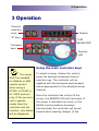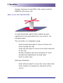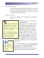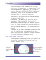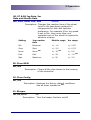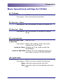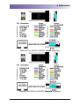
1
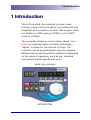
altuS Clip Controller HT252/HT262 Users Manual Software version: HT252 - 2.00 HT262 – 2.1 History Date Jan 2015 Jan 2012 June 2009 Oct 2007 April 2008 Description Amendment to Record stop HT262 Loop mode (Menu item 15) HT262 added – altuS manual Version 2 altuS manual Version 1.0 Loop play added Version 2.2 2.1 2.0 1.0 1.01 altuS VTR and Disk controller Hi Tech Systems Ltd Holbrook House Oakley Lane Oakley Basingstoke Hampshire RG23 7JY Tel: Fax: Email: Web: +44 (0) 1256 780880 +44 (0) 1256 782600 [email protected] www.hitechsys.com The hardware/software and manual are copyright 1998 - 2012 by Hi Tech Systems Ltd. All rights reserved. The operating code is licensed by Hi Tech to the original purchaser only. It is not permitted to copy, sell or use this product in any other way than is intended. All trademarks acknowledged. According to the U.K. copyright law, unauthorised reproduction of software can be subject to civil damages. The information in this document is subject to change without notice. In no event will Hi Tech Systems Ltd be liable for direct, indirect, incidental or consequential damages resulting from any defect in the software even if they have been advised of such damages. 2015 Hi Tech Systems Limited altuS VTR and Disk controller Contents 1 INTRODUCTION 1 2 INSTALLATION 3 Unpacking 3 Desk mounting 3 Warnings – read before installation or use 4 EXTERNAL CONNECTIONS 5 Power requirements 5 Connecting a server channel 5 RJ45 connector pin out 3 OPERATION Using the main controller keys 6 7 7 What is the CLIP NAVIGATOR? 8 What are the S keys? 9 How to Load Clips 9 How to Jog, shuttle and variable 10 How to record 11 How to stop record 11 How to eject a clip 11 How to store clips into memory 11 Trimming clips (non destructive) How to enter trim points 12 12 A trim IN point can be entered ‘on the fly’ while the server is in play by pressing the MARK IN key, and a trim OUT point can be similarly entered by pressing the MARK OUT key. 12 How to loop a clip 13 Advanced Operations 14 Entering clip names for loading or recording clips 14 How to select both server channels for group control 14 How to clear the memory, and restore to factory default? 15 How to change the timecode source 15 How to enter and exit the altuS SETUP menu. 17 How to change operational parameters in the SETUP menu 17 MENU OPERATIONAL SETTINGS FOR HT252 18 MENU OPERATIONAL SETTINGS FOR HT262 21 2015 Hi Tech Systems Limited altuS VTR and Disk controller 4 ADDENDUM 24 OUTLINE DIMENSIONS 24 SOFTWARE UPDATES 24 CABLE PIN OUT REFERENCE 25 NOTES ON PC SERIAL CONNECTORS 26 5 SPECIFICATION 2015 Hi Tech Systems Limited 28 1 Introduction 1 Introduction The Hi Tech altuS clip controller provide a userfriendly remote control interface for professional and broadcast disk recorders (servers) that support either the Odetics or AMP protocol (HT252) or the VDCP protocol (HT262). The controller utilises a control wheel, called “smart wheel” an implementation of Haptic technology – “Haptic” is Greek for the science of touch. The controller can be programmed to give the operator different tactile and kinesthetic sensations depending on the mode of operation, such as jog, indented incremental shuttle speeds and so on. altuS clip controller HT252/HT262 2015 Hi Tech Systems Limited 1 1 Introduction Accessories supplied: • 2 RJ45 to 9 pin ‘D’ type adaptors • User’s manual (this manual) on CD Available options: • Spare RJ45 to 9 pin ‘D’ type adaptor male for direct connection to server channel • Spare RJ45 to 9 pin ‘D’ type adaptor female for connection to end of "standard" RS422 cable 2 altuS VTR and Disk controller 2 Installation 2 Installation The altuS clip controller is designed as desk-top unit. Unpacking The Hi Tech Systems altuS clip controller is shipped in a carton, which contains other optional items within the packing, and care should be taken to ensure that these are not thrown away. The contents of the carton are as indicated on the delivery note. Carefully unpack and check for shipping damage and shortages. Report without delay, any damage or shortages to Hi Tech Systems Ltd. Desk mounting The altuS desk mounting controller require no special fixings, but can be mounted into a desk as a ‘drop through’ unit. Outline dimensions for all models are given in the Addendum at the back of this manual. 2015 Hi Tech Systems Limited 3 2 Installation Warnings – read before installation or use Only suitably qualified engineers should carry out maintenance. The controller consists of electronic parts. Do not drop the controller or bump it against other objects or place the controller near heat sources such as radiators or air conditioning ducts. Care should be taken so that solid objects or liquid do not fall into the controller enclosure. Clean the case with a soft dry lint free cloth, or a soft cloth lightly moistened with a mild detergent solution. Do not use any type of solvent such as alcohol, which might damage the special finish. 4 altuS VTR and Disk controller 2 Installation External connections altuS HT252/HT262 rear view altuS HT252/HT262 side view Power requirements The HT252 and HT262 are shipped with an adaptor for a 12V DC supply. The adaptor should be connected to Mains AC 100V – 240V. The 4 pole XLR should click into the rear of the controller. Connecting a server channel The RS422 server control ports are implemented as RJ45 connectors to make the best use of space at the rear of a desk-top unit. To convert RS422 ports on the server and other controlled devices to use RJ45 patch cables use the 2015 Hi Tech Systems Limited 5 2 Installation supplied converter at the server end. Either channel can be connected as a player OR recorder, the controller does not distinguish between the two. It up to the user to correctly connect and configure the server channels as players or recorders. Converts server serial ports to RJ45 RJ45 connector pin out Pin No Description 1 Chassis Gnd 2 Rx A data 3 Tx B data 4 Tx Gnd 5 N.C 6 Rx Gnd 7 Rx B data 8 Tx A data RJ45 Connector CAT 5 remote cables are connected to the RJ45 sockets It is recommended not to exceed 100 metres of CAT 5 cable. 6 altuS VTR and Disk controller 3 Operation 3 Operation Channel selection keys Display “S” keys “CLIP NAVIGATOR” Transport keys Remote LED Using the main controller keys The server To select a server channel for control, MUST be enabled press the desired numbered channel for Odetics or AMP selection key. The controller will be remote control updated with the timecode and transport when using a status appropriate for the attached server HT252. A HT262 is channel. for VDCP protocol Once the controller has control of the only. If the server is server, the REMOTE LED will illuminate. If set to operate the server is switched into local, or the locally then the RS422 communications becomes controller will not disconnected, the controller will sound function, only status several short warning ‘bleeps’ (if the will be displayed. 2015 Hi Tech Systems Limited 7 3 Operation bleeper has been turned ON in the menu) and the REMOTE LED will go off. What is the CLIP NAVIGATOR? A multi directional switch that enables several operations to be performed from one control. For instance when: The controller is in playback mode Push forward and back to move a frame at a time through the clip. Push left and right to move to the start and end of the clip. Rotate clockwise and anti-clockwise to scroll forward and backwards through clips. Push to load a clip. Entering characters Push left and right to move the curser back and forth. Rotate to change the character at the curser. 8 altuS VTR and Disk controller 3 Operation What are the S keys? The S keys are shortcut keys to 5 memory locations. Any clip or trimmed clip can be stored to any of the 5 keys for immediate shot recall or, indeed, any of the 99 internal memory locations. How to Load Clips Clips can be loaded onto a channel in the following ways: 1. From the server, by browsing (BROWSE DSK). The first 255 clips Press SHIFT + S1. Rotate the CLIP are displayed, then wraps NAVIGATOR clockwise and anti- around to 0. There is no clockwise to scroll forward and limit to the number of clips backwards through the server’s that can be browsed. database of clips. The number at the top right hand corner of the When browsing backwards there is a short delay while the next set of clips is stored into memory. display is the “clip counter”, and indicates the position of the clip in the server’s database. Press the CLIP NAVIGATOR to load the clip. Press SHIFT to exit browse mode and return the display to show the previously loaded clip. Press and release the SHIFT key to esc from any operation. 2. From internal memory (if a clip has already been stored), by browsing (BROWSE MEM). Press SHIFT + S2. Rotate the CLIP NAVIGATOR clockwise and anti-clockwise to scroll forward and backwards through the 2015 Hi Tech Systems Limited 9 3 Operation controller’s memory. The number at the top right hand corner of the display is the “mem counter”, and indicates the position of the clip in the controller’s memory. Press the CLIP NAVIGATOR to load the clip. Press SHIFT to exit browse mode and return the display to show the previously loaded clip. 3. By entry of clip name using the CLIP NAVIGATOR or keyboard (KBD ENT). Press SHIFT + S3. Enter a clip name from the pc keyboard or CLIP NAVIGATOR. Press the CLIP NAVIGATOR to load the clip. Press SHIFT to exit and return the display to show the previously loaded clip. 4. From an S-KEY directly (if a clip has already been stored). Press any “S” key that is illuminated to load clip. Wait until the key flashes to indicate the clip has cued before playing the clip, unless the controller has been set to play the clip immediately on recall. How to Jog, shuttle and variable Press the wheel to enter JOG mode. Press again to go into shuttle. Press and hold the wheel to go into variable playback mode. Jog and clip navigator shuttle is ON (flash) LEDs 10 Remote altuS VTR and Disk controller 3 Operation How to record 1. Press the REC key – you are prompted to enter a clip name (clip id). The altuS range does NOT perform editing functions. 2. Use the pc keyboard or CLIP NAVIGATOR to enter a name. 3. Press Enter from the pc keyboard or the CLIP NAVIGATOR to create the clip – now ready to start recording. 4. Pres REC + PLAY to start recording. How to stop record Press and hold the shift button and press the blue stop key, this stops the clip recording or stops the clip playback if that port is controlling the play out of the server. How to eject a clip Press and hold the blue stop key for more than 1 second. How to store clips into memory When a clip is displayed on the controller it is possible to store into many locations. There are 5 S keys and another 99 memory locations. By pressing and holding the shift key then pressing the S 5 key it is possible to select a location with the navigation wheel. Once the desired location has been found, press down on the navigation wheel to store the clip. 2015 Hi Tech Systems Limited 11 3 Operation Trimming clips (non destructive) Trimmed clips are timecode reference points that are stored with a clip that Any clip that was loaded by browsing the server can be trimmed, but if another clip is loaded then the trim points are lost. Only clips stored in memory can have permanent trims. has been stored in the memory on the controller. Each clip memory location is stored with a clip name and an In point and / or Out point. How to enter trim points A trim IN point can be entered ‘on the fly’ while the server is in play by A clip must have a trim In point. Otherwise put a 1 frame trim In point. Mark In key 12 pressing the MARK IN key, and a trim OUT point can be similarly entered by pressing the MARK OUT key. Mark Out key altuS VTR and Disk controller 3 Operation How to loop a clip It is possible to loop a clip indefinitely until STOP is pressed. Press and hold The clip MUST have a trim IN and OUT point, and re- loaded to work correctly. Channel Key the illuminated channel selection key and the PLAY key. Play key HT262 – Adjust amount of frames required by the server to reload the clip for looping. Loop cmd delay – Menu item 15. 2015 Hi Tech Systems Limited 13 3 Operation Advanced Operations Entering clip names for loading or recording clips KEYBOARD -> A standard PC keyboard can be connected to the controller to Some servers my not distinguish between upper and lower case characters. aid in naming clips for recording and loading clips for playback. Connect a standard PC keyboard to the left side of the controller. PC keyboard connector How to select both server channels for group control Press both selection keys at the same time. To ungroup press both keys The device selected first is treated as the Master and its status (e.g. PLAY, STOP etc) is shown in the display. If a different channel is then selected it now becomes the Master. 14 again. altuS VTR and Disk controller 3 Operation How to clear the memory, and restore to factory default? There are times when you may want to completely erase all the memory locations of the controller and return the menu settings to there factory defaults for example after a software upgrade. 1 Turn off the power. 2 Press and hold the STOP key. 3 Turn the power back on. 4 Release the STOP key. How to change the timecode source Change the timecode settings in the menu (see the menu section in this manual for entering the menu). The TC setting changes the time code source data (hours, minutes, seconds and frames) that is displayed on the time code display of the controller for the connected server. The selections are different on the HT252 to the HT262. If the display shows [--:--:--:--] then no valid time code can be read. The HT252 has the following timecode source options. CTL Tape running time (hours, minutes, seconds and frames) is computed from the recorded control (CTL) 2015 Hi Tech Systems Limited 15 3 Operation signal during playback, or a count of control signal pulses during recording. These counters do not usually keep a highly accurate track of tape position. LTC or Longitudinal time code in either 24 hour or +/- 12-hour format is usually recorded on an audio track on the tape. LTC is read by the internal time code reader during playback or longitudinal time code reader during recording. VITC - Vertical interval time code. This is recorded on an invisible area in the video track, and during playback read by the internal time code reader or vertical interval time code reader during recording. AUTO Time code is selected automatically by the server depending Time code source is selected globally for both channels on the speed of the tape. Typically VITC is selected when the tape transport speed is up to half speed, and LTC when it is more than half speed. The HT262 has the following timecode source options. SOM – Start of Message / Media. The recording starts when Video/Audio is detected. 16 altuS VTR and Disk controller 3 Operation ZERO – Resets the counter and always records from 00:00:00:00 TC – Records from a set Timecode position. How to enter and exit the altuS SETUP menu. There are times when you may want to change certain altuS operational parameters. This is accomplished via its SETUP menu. It is here where you will be offered setup parameters to choose from. To enter and exit SETUP: Press and hold the REC key and the REW key. How to change operational parameters in the SETUP menu Turn the CLIP NAVIGATOR to “point” the display chevron to the line item you wish to change, a chevron > indicates the active display line. Press and hold down the CLIP NAVIGATOR to change the parameter of interest. Change the parameter by turning the WHEEL. 2015 Hi Tech Systems Limited 17 3 Operation Menu Operational settings for HT252 01. TC Mode CTL, LTC, VITC, AUTO AUTO DEF Description: Set the timecode standard. 02. Load method Load on S key, Load on NAV SW Load on S key DEF Description: Effects the loading of the clips when loading from the S keys. Load on S key Pressing an S key loads stored clip immediately. Load on NAV SW Pressing an S key displays stored clip, now have to press CLIP NAVIGATOR. 03. Load mode Stop, Play Stop DEF Description: Effects how the loaded clip behaves. Stop Loads the clip and goes into still. Play Loads the clip and immediately goes into play. 04. Rec Inhib DSKx NO or Yes NO DEF Description: Inhibits recording on selected channel. 05. Lock DSK NO or YES NO DEF Description: Locks the PLAY and RECORD transport controls only. Note: the controller must be in PLAY or RECORD first before turning this mode on. Enter menu again to turn OFF lock. 18 altuS VTR and Disk controller 3 Operation 06, 07 & 08 Jog Rate, Var Rate and Shuttle Rate Min, Slow, Norm, Fast, Max Normal DEF Description: Changes the reaction time of the wheel input to the tape being replayed to compensate for disk and operator preference. For example if the Jog speed is set to Min, then more than one complete turn of the wheel is required to advance a frame. Setting Jog reaction time Shuttle range Var range Min Minimum +/- 1.0 +/- 0.25 Slow Slow +/- 2.0 +/- 0.33 Norm Norm Fast Fast +/- 24 +/- 1.0 Max Maximum +/- 50 +/- 2.0 DEF +/- 15 DEF +/- 0.5 DEF 09. Clear MEM NO, YES Description: Clears all the clips stored in the memory of the controller. 10. Clear Config NO, YES Description: Restores the factory default conditions. See all items marked as DEF. 11. Bleeper Off, On, Error Off DEF Description: Turn the beeper function on/off. 2015 Hi Tech Systems Limited 19 3 Operation 12. Vid Std PAL, NTSC PAL DEF Description: Sets the T/C to run on either PAL or NTSC standard 13. Protocol Odetics, AMP Odetics DEF Description: Use Odetics or AMP (Odetics with extended commands) 14. EE mode auto or full AUTO ON, AUTO OFF, FULL ON, FULL OFF AUTO ON DEF Description: Change the EE function from automatic to manual. 20 altuS VTR and Disk controller 3 Operation Menu Operational settings for HT262 01. TC Mode SOM, ZERO, TC ZERO DEF Description: Set the timecode standard. 02. Rec Len - Hours Description: Set the amount of Hours to Record 03 DEF 03. Rec Len - Mins Description: Set the amount of Minutes to Record 00 DEF 04. Load method Load on S key, Load on NAV SW Load on S key DEF Description: Effects the loading of the clips when loading from the S keys. Load on S key Pressing an S key loads stored clip immediately. Load on NAV SW Pressing an S key displays stored clip, now have to press CLIP NAVIGATOR. 05. Load mode Stop, Play Stop DEF Description: Effects how the loaded clip behaves. Stop Loads the clip and goes into still. Play Loads the clip and immediately goes into play. 2015 Hi Tech Systems Limited 21 3 Operation 06. Lock DSK1 or 2 NO or YES NO DEF Description: Locks the PLAY and RECORD transport controls only. DSK1 for port 1 and DSK2 for port 2. Note: the controller must be in PLAY or RECORD first before turning this mode on. Enter menu again to turn OFF lock. 07. Clear MEM NO, YES NO DEF Description: Clears all the clips stored in the memory of the controller. 08. Clear Config NO, YES NO DEF Description: Restores the factory default conditions. See all items marked as DEF. 09. Bleeper Off, On, Error Off DEF Description: Turn the beeper function on/off. 10. Vid Std PAL, NTSC PAL DEF Description: Sets the T/C to run on either PAL or NTSC standard 22 altuS VTR and Disk controller 3 Operation 11. Vari length ID Off, On Off DEF Description: Sets the Character length from 32 to 8 for Server applications without Variable ID when switched ON. 12. Port Number 001 - 127 DEF 001 Description: Both Comm ports can be individually assigned a port number 1 – 127 to match the destination server port number. 13. Port Type Player, Recorder, Both Player DEF Description: Sets a Comms port behaviour when controlling a server. 14. EE mode ON, OFF, AUTO ON DEF Description: Switches the EE mode of the controlled device. 15. Loop Cmd delay 01-50 5 Description: 2015 Hi Tech Systems Limited DEF Adjust the amount of frames required by the server to re-load the clip for successful looping. 23 4 Addendum 4 Addendum Outline dimensions The altuS has the following outline dimensions: Software Updates Download the software update wizard actiV8 from the Hi Tech Systems support web site at: http://www.hitechsys.co.uk/html/support/support_overview.html and contact Hi Tech Systems for the latest software version. 24 altuS VTR and Disk controller 4 Addendum RJ45 to D type - RS422 cable Cable pin out reference The following diagrams are provided for those wishing to make their own cables. 2015 Hi Tech Systems Limited 25 4 Addendum RJ45 to D type - RS422 cable RJ45 to D type – RS232 cable Making a software upgrade serial cable Notes on PC serial connectors Some computers, particularly laptops have odd earth arrangements on the RS232 connector, making the download problematic. If possible, use a desktop PC for performing s/w updates. 26 altuS VTR and Disk controller 4 Addendum Making the RJ45 to RS422 male adapters Making the RJ45 to RS422 female adapters 2015 Hi Tech Systems Limited 27 5 Specification 5 Specification Control ports Communication Format: RS-422-A Communication Channel: Full Duplex Data Signalling Rate: 38.4 Kb/s (K bits per second) Communication Protocol: Serial connectors: servers controlled: Odetics, AMP and VDCP 9 pin RS422 2 x RJ45 – 8 pin sockets That support the Odetics or AMP RS422 9 pin protocol Power Mains input: DC Mains Adaptor Voltage: 12V Power consumption: Less than 5 watts General Operating Temp: 0 - 35 Deg C 28 altuS VTR and Disk controller