1
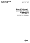
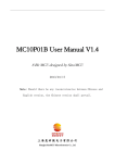
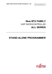
Fujitsu Microelectronics (Shanghai) Co., Ltd.
Application Note
MCU-AN- 500028-E-14
F²MC-8FX FAMILY
8-BIT MICROCONTROLLER
MB95200H/210H SERIES
SOP8/SOP16/SOP20
PGM ADAPTOR
APPLICATION NOTE
SOP8/SOP16/SOP20 PGM ADAPTOR V1.4
Revision History
Revision History
Date
2009-1-14
2009-2-27
2009-3-4
2009-3-23
2009-11-02
Author
Edison Zhang
Edison Zhang
Edison Zhang
Edison Zhang
Edison Zhang
Change of Records
V1.0, First draft
V1.1, Add SOP16 PGM adaptor usage
V1.2, Modify
V1.3, Add PGM adaptor PN information
V1.4, Add SOP8 PGM adaptor usage
This manual contains 20 pages.
1. The products described in this manual and the specifications thereof may be changed without prior notice.
To obtain up-to-date information and/or specifications, contact your Fujitsu sales representative or Fujitsu
authorized dealer.
2. Fujitsu will not be liable for infringement of copyright, industrial property right, or other rights of a third party
caused by the use of information or drawings described in this manual.
3. The contents of this manual may not be transferred or copied without the express permission of Fujitsu.
4. The products contained in this manual are not intended for use with equipments which require extremely
high reliability such as aerospace equipments, undersea repeaters, nuclear control systems or medical
equipments for life support.
5. Some of the products described in this manual may be strategic materials (or special technology) as defined
by the Foreign Exchange and Foreign Trade Control Law. In such cases, the products or portions thereof
must not be exported without permission as defined under the law.
© 2008 Fujitsu Microelectronics (Shanghai) Co., Ltd.
MCU-AN- 500028-E-14 – Page 2
SOP8/SOP16/SOP20 PGM ADAPTOR V1.4
Revision History
REVISION HISTORY ............................................................................................................ 2
1 INTRODUCTION.............................................................................................................. 4
2 APPLICATION ENVIRONMENT ...................................................................................... 6
2.1
Mother board........................................................................................................... 6
2.2
Debug tool............................................................................................................... 6
2.3
SOFTUNE ............................................................................................................... 7
2.4
USB programmer .................................................................................................... 7
3 PROGRAMMING FUNCTION PROCESS........................................................................ 8
3.1
Hardware modification............................................................................................. 8
3.2
Use MB95200 series USB programmer to program............................................... 10
3.3
Use F2MC-8L/8FX SOFTUNE to program............................................................. 11
4 EVALUATION PROCESS.............................................................................................. 16
4.1
Normal run process ............................................................................................... 16
4.2
Conclusion ............................................................................................................ 17
4.3
Practicable MCU PN table..................................................................................... 18
5 ADDITIONAL INFORMATION ....................................................................................... 19
6 APPENDIX ..................................................................................................................... 20
MCU-AN- 500028-E-14 – Page 3
SOP8/SOP16/SOP20 PGM ADAPTOR V1.4
Chapter 1 Introduction
1 Introduction
As accessory of Starter Kit, MB95200H/210H SOP8/SOP16/SOP20 PGM adaptor is
developed for On-Board Programming and Debugging of MB95200H/210H series
SOP8/SOP16/SOP20 package MCU. The picture of MB95200H/210H SOP8/SOP16/SOP20
PGM adaptor is shown in Figure 1.1, Figure1.2 and Figure1.3.
The socket is used to place MB95200H/210H series SOP8/SOP16/SOP20 package MCU,
10-pin connector is used to connect with mother board. The PN of MB95200H/210H SOP8
PGM adaptor is FMCDC-MB95200-PGMA-01008. The PN of MB95200H/210H SOP16 PGM
adaptor is FMCDC-MB95200-PGMA-01016. The PN of MB95200H/210H SOP20 PGM
adaptor is FMCDC-MB95200-PGMA-01020.
Note:
The shape of SOP8 PGM adaptor is as same as SOP16 PGM adaptor, but the left side pins of
SOP16 socket are already removed away to avoid misplacing, and the right part is used to place
SOP8 packet MCU, shown in the Figure1.3.
Figure 1.1: MB95200H/210H SOP20 PGM adaptor
MCU-AN- 500028-E-14 – Page 4
SOP8/SOP16/SOP20 PGM ADAPTOR V1.4
Chapter 1 Introduction
Figure 1.2: MB95200H/210H SOP16 PGM adaptor
Figure 1.3: MB95200H/210H SOP8 PGM adaptor
MCU-AN- 500028-E-14 – Page 5
SOP8/SOP16/SOP20 PGM ADAPTOR V1.4
Chapter 2 Application environment
2 Application environment
This chapter introduces application environment of MB95200H/210H SOP8/SOP16/SOP20
PGM adaptor.
2.1
Mother board
The mother board of MB95200H/210H SOP8/SOP16/SOP20 PGM adaptor is
MB95200H/210H EV-board V1.5, as below picture. It can be gotten from MB95200 MCU
Starter Kit (PN: MB2146-410-01-E).
Figure 2.1: MB95200H/210H EV-board V1.5
2.2
Debug tool
The debug tool is BGMA (BGM Adaptor), the type of it is MB2146-08-E, as below picture. It
can be gotten from MB95200 MCU Starter Kit (PN: MB2146-410-01-E).
Figure 2.2: BGM Adaptor
MCU-AN- 500028-E-14 – Page 6
SOP8/SOP16/SOP20 PGM ADAPTOR V1.4
Chapter 2 Application environment
2.3
SOFTUNE
SOFTUNE is used to program and debug, as software development environment. The
version of it is F2MC-8L/8FX SOFTUNE Workbench V30L31, as below picture. It can be
gotten from MB95200 MCU Starter Kit (PN: MB2146-410-01-E), or downloaded from.
Web: http: //www.fujitsu.com/cn/fmc/service/mcu/tools.
Figure 2.3: SOFTUNE Version
2.4
USB programmer
The MB95200 series USB programmer is as below picture. It can be gotten from MB95200
MCU Starter Kit (PN: MB2146-410-01-E), or downloaded from
Web: http: //www.fujitsu.com/cn/fmc/service/mcu/tools.
Figure 2.4: MB95200 series USB programmer
MCU-AN- 500028-E-14 – Page 7
SOP8/SOP16/SOP20 PGM ADAPTOR V1.4
Chapter 3 Programming function process
3 Programming function process
This chapter introduces programming steps using either MB95200 series USB programmer
or F2MC-8L/8FX SOFTUNE Workbench V30L31.
MB95200 series MCU can be programmed through MB95200 series USB programmer or
F2MC-8L/8FX SOFTUNE Workbench V30L31. Section 3.2 introduces programming with
MB95200 series USB programmer. Section 3.3 introduces programming with F2MC-8L/8FX
SOFTUNE Workbench V30L31.
3.1
Hardware modification
(1) MB95200H/210H EV-board V1.5 is mother board of MB95200H/210H SOP8/
SOP16/SOP20 PGM adaptor board, which already has MB95F204K soldered on it.
Therefore, we should remove the MB95F204K chip from mother board first.
Remove MCU
.
Figure 3.1: Remove MCU from mother board
(2) MB95200H/210H EV-board has provided many general MCU periphery modules,
including LED, Key, UART, Buzzer, AD sample and so on. Many jumpers on the mother
board are used to connect or disconnect MCU with periphery modules. For general
application, these jumpers should be short. For special application, user needs to open
these jumpers and test IO port from 10-pin connector on the adaptor board. If you want
to know more information about MB95200H/210H EV-board, please refer to SKT
MB2146-410-01-E User Manual.
MCU-AN- 500028-E-14 – Page 8
SOP8/SOP16/SOP20 PGM ADAPTOR V1.4
Chapter 3 Programming function process
Short
jumper
Figure 3.2: Short jumpers on mother board
(3) Place MB95F204K chip on the SOP20 socket (or MB95F223K chip on the SOP16
socket, or MB95F213K chip on the SOP16 socket).
Lock
Figure 3.3: Place MCU on adaptor board
MCU-AN- 500028-E-14 – Page 9
SOP8/SOP16/SOP20 PGM ADAPTOR V1.4
Chapter 3 Programming function process
(4) At last, fix the adaptor board on the mother board.
Figure 3.4: Fix adaptor board on the mother board
3.2
Use MB95200 series USB programmer to program
(1) Open MB95200 series USB programmer
(2) Select MCU type (MB95F204H/K for MB95F204K, MB95F223H/K for MB95F223K,
MB95F213H/K for MB95F213K)
(3) Select mhx file at the path: Current project DIR\Debug\ABS
(2)
(3)
Figure 3.5: Select MCU type and Hex File
MCU-AN- 500028-E-14 – Page 10
SOP8/SOP16/SOP20 PGM ADAPTOR V1.4
Chapter 3 Programming function process
(4) Click Full Operation to do programming.
Figure 3.6: Click Full Operation
(5) The USB programmer also provides single operation, including Erase, Blank Check,
Program, Read & Compare and Copy.
3.3
Use F2MC-8L/8FX SOFTUNE to program
(1) Connect BGMA to PC
(2) Connect EV-board to BGMA
(3) Power on the EV-board
(1)
(2)
(3)
Figure 3.7: Indicate process 1-3
MCU-AN- 500028-E-14 – Page 11
SOP8/SOP16/SOP20 PGM ADAPTOR V1.4
Chapter 3 Programming function process
(4) Open a project (E.g. IO_LED) using SOFTUNE
Figure 3.8: Open demo project
(5) As original IO_LED demo is for MB95F204K MCU, so if MB95F223K is programmed
on SOP16 PGM adaptor or MB95F213K is programmed on SOP8 PGM adaptor, we
should change MCU type to MB95F223K/ MB95F213K in “Project/Setup Project…/MCU”.
Change MCU
Figure 3.9: Set MCU type
(6) After MCU is changed, all sections set before are all cleared, so we should reset the
sections. In “Project/Setup Project…/Linker”, set “Disposition/Connection” in Category, click
_INROM01, click “Set Section…” and it will pop a dialog window as Figure 3.11, then set two
sections: Const(named @INIT), Dirconst(named @DIRINIT) as Figure 3.12 and 3.13. If
MB95F204K is programmed on SOP20 PGM adaptor, the step (5) and (6) should be
skipped.
MCU-AN- 500028-E-14 – Page 12
SOP8/SOP16/SOP20 PGM ADAPTOR V1.4
Chapter 3 Programming function process
(6.1) Select
(6.2) Click
(6.3) Click
Figure 3.10: Disposition display window
Figure 3.11: Section setting window
MCU-AN- 500028-E-14 – Page 13
SOP8/SOP16/SOP20 PGM ADAPTOR V1.4
Chapter 3 Programming function process
(6.5) set section name
(6.6) Click
(6.4) Select
Figure 3.12: Set Const section
(6.8) set section name
(6.9) Click
(6.7) Select
Figure 3.13: Set Dirconst section
MCU-AN- 500028-E-14 – Page 14
SOP8/SOP16/SOP20 PGM ADAPTOR V1.4
Chapter 3 Programming function process
(7) Compile project
(8) Start debug
Figure 3.14: Start debug
(9) Run (code update)
(10) End debug
MCU-AN- 500028-E-14 – Page 15
SOP8/SOP16/SOP20 PGM ADAPTOR V1.4
Chapter 4 Evaluation process
4 Evaluation process
This chapter introduces evaluation steps of normal run status.
4.1
Normal run process
(1) Power off EV-board
(2) Disconnect BGMA with EV-board
(1)
(2)
Figure 4.1: Indicate process 1-2
(3) Short J2 (mode switch)
(4) Power on
(4)
(3)
Figure 4.2: Indicate process 3-4
MCU-AN- 500028-E-14 – Page 16
SOP8/SOP16/SOP20 PGM ADAPTOR V1.4
Chapter 4 Evaluation process
(5) Watch the EV-board, if IO_LED demo project is used, the LED2-4 is circularly twinkling
(Mother board + SOP20 PGM with MB95F204K) or the LED2 is twinkling (Mother board
+ SOP16 PGM adaptor with MB95F223K or Mother board + SOP8 PGM adaptor with
MB95F213K).
Figure 4.3: The LED2-4 is circularly twinkling.
4.2
Conclusion
(1) MB95200H/210H SOP8/SOP16/SOP20 PGM adaptor board is accessory of
MB95200H/210H MCU Starter Kit (PN: MB2146-410-01-E) to support SOP8/
SOP16/SOP20 package MCU programming with socket.
(2) The Starter Kit’s original functions including debug and normal run are still remained.
(3) The PN of PGM adaptor is FMCDC-MB95200-PGMA-0x0xx
0x: SOP 01, SSOP 02, DIP 03, SDIP 04, QFN 05, TSSOP-> 06
0xx: Pin count (e.g. 008 means 8pin MCU)
MCU-AN- 500028-E-14 – Page 17
SOP8/SOP16/SOP20 PGM ADAPTOR V1.4
Chapter 4 Evaluation process
4.3
Practicable MCU PN table
MCU Series
Part Number
Footprint
MB95200 series
MB95F204HPF-G-SNE2
SOP20
MB95F204KPF-G-SNE2
MB95F203HPF-G-SNE2
MB95F203KPF-G-SNE2
MB95F202HPF-G-SNE2
MB95F202KPF-G-SNE2
MB95220 series
MB95F223HPF-G-SNE1
SOP16
MB95F223KPF-G-SNE1
MB95F222HPF-G-SNE1
MB95F222KPF-G-SNE1
MB95210 series
MB95F214HPF-G-SNE2
MB95F214KPF-G-SNE2
MB95F213HPF-G-SNE2
MB95F213KPF-G-SNE2
MB95F212HPF-G-SNE2
MB95F212KPF-G-SNE2
MCU-AN- 500028-E-14 – Page 18
SOP8
SOP8/SOP16/SOP20 PGM ADAPTOR V1.4
Chapter 5 Additional Information
5 Additional Information
For more information about how to use MB9595200H/210H EV-board, BGM Adaptor and
SOFTUNE, please refer to SKT MB2146-410-01-E User Manual, or visit
Web: http://www.fujitsu.com/cn/fmc/services/mcu/
MCU-AN- 500028-E-14 – Page 19
SOP8/SOP16/SOP20 PGM ADAPTOR V1.4
Chapter 6 Appendix
6 Appendix
Figure 1.1: MB95200H/210H SOP20 PGM adaptor ............................................................... 4
Figure 1.2: MB95200H/210H SOP16 PGM adaptor ............................................................... 5
Figure 1.3: MB95200H/210H SOP8 PGM adaptor ................................................................. 5
Figure 2.1: MB95200H/210H EV-board V1.5 ......................................................................... 6
Figure 2.2: BGM Adaptor ....................................................................................................... 6
Figure 2.3: SOFTUNE Version............................................................................................... 7
Figure 2.4: MB95200 series USB programmer....................................................................... 7
Figure 3.1: Remove MCU from mother board ........................................................................ 8
Figure 3.2: Short jumpers on mother board............................................................................ 9
Figure 3.3: Place MCU on adaptor board ............................................................................... 9
Figure 3.4: Fix adaptor board on the mother board .............................................................. 10
Figure 3.5: Select MCU type and Hex File ........................................................................... 10
Figure 3.6: Click Full Operation............................................................................................ 11
Figure 3.7: Indicate process 1-3........................................................................................... 11
Figure 3.8: Open demo project............................................................................................. 12
Figure 3.9: Set MCU type..................................................................................................... 12
Figure 3.10: Disposition display window............................................................................... 13
Figure 3.11: Section setting window..................................................................................... 13
Figure 3.12: Set Const section ............................................................................................. 14
Figure 3.13: Set Dirconst section ......................................................................................... 14
Figure 3.14: Start debug ...................................................................................................... 15
Figure 4.1: Indicate process 1-2........................................................................................... 16
Figure 4.2: Indicate process 3-4........................................................................................... 16
Figure 4.3: The LED2-4 is circularly twinkling....................................................................... 17
MCU-AN- 500028-E-14 – Page 20