1
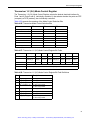
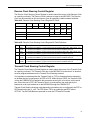
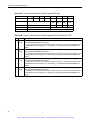
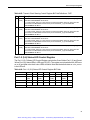
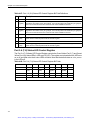
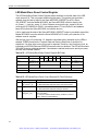
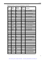
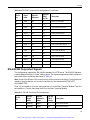
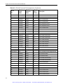
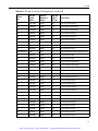
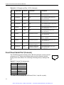
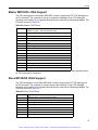
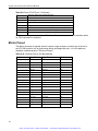
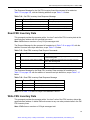
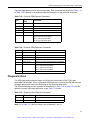
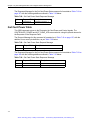
Chapter 7: System Management Bus and Intelligent Platform Management
The Response Message for the Diagnostic Echo command is formatted as shown in Table 7-22
with the following additions:
Table 7-22: Diagnostic Echo Response Message
Byte
Response Field
Description
8 to N
Count Returned
Must be at least 1 but no more than 24 (bytes)
N+1
Checksum #2
Checksum of bytes 4 - N
Note: “N” in Table 7-22 refers to a byte count of between 8 and 31.
Get Card Power Status
This OEM command provides the Requester with the current power status of the card. The PM
will Respond with the power status of the card as determined by the POWER_GOOD signal pin
on the general-purpose parallel I/O port of the PM microcontroller. This signal is generated by
an on-board power management module and indicates that all voltage rails are within the
specified limits.This command also reports the state of additional card status signals such as
EJECTOR_SWITCH, HEALTHY, P1_BDSEL and the SMB_ENABLED signal.
Table 7-23: Bit Assignments for Card Power Status Byte
Bit
Signal
Description
Values
7
P1_BDSEL
BDSEL from the PCI Bus
0 indicates BDSEL is FALSE
1 indicates that BDSEL is TRUE
6
NC
5
NC
4
EJECTOR_SWITCH
Ejector Switch
0 indicates EJECTOR_SWITCH is Closed
1 indicates that EJECTOR_SWITCH is OPEN
3
HEALTHY
POWER_GOOD and no fault
0 indicates that HEALTHY is FALSE
1 indicates HEALTHY is TRUE
2
NC
1
SMB_ENABLE
SMB (PM) Enable Switch
0 indicates SMB is Disabled
1 indicates that SMB is Enabled
0
POWER_GOOD
POWER_GOOD output from
Hot-Swap Controller
0 indicates POWER_GOOD is FALSE
1 indicates that POWER_GOOD is TRUE
The Request Message for this command is formatted as in Table 7-19 on page 167, with the
addition of one or more byte definitions, as per Table 7-24.
Table 7-24: Get Card Power Status Request Message
Byte
Request Field
Description
7
Checksum #2
Checksum of bytes 4 - 6
168
Artisan Technology Group - Quality Instrumentation ... Guaranteed | (888) 88-SOURCE | www.artisantg.com