1
OPERATION MANUAL
FX-20P-E HANDY PROGRAMMING PANEL
FX-20P-E Handy programming panel
Foreword
•
This manual contains text, diagrams and explanations which will guide the reader in the correct installation
and operation of the FX-20P-E HANDY PROGRAMMING PANEL. It should be read and understood before
attempting to install or use the unit.
•
Further information can be found in the FX0/FX0S/FX0N/FX1S/FX/FX1N/FX2N/FX2NC Series Hardware Manual
and FX Series Programming Manual (ΙΙ).
•
If in doubt at any stage of the installation of FX-20P-E HANDY PROGRAMMING PANEL always consult a
professional electrical engineer who is qualified and trained to the local and national standards which apply to
the installation site.
•
If in doubt about the operation or use of FX-20P-E HANDY PROGRAMMING PANEL please consult the
nearest Mitsubishi Electric distributor.
•
This manual is subject to change without notice.
FX-20P-E Handy programming panel
FX-20P-E HANDY PROGRAMMING
PANEL
Manual number : JY992D82301
OPERATION MANUAL
Manual revision : C
Date
: January 2007
FX-20P-E Handy programming panel
ii
FX-20P-E Handy programming panel
Guidelines for the Safety of the User and Protection of the FX20P-E-HANDY
PROGRAMMING PANEL.
This manual provides information for the use of the FX-20P-E-HANDY PROGRAMMING
PANEL. The manual has been written to be used by trained and competent personnel. The
definition of such a person or persons is as follows:
a) Any engineer who is responsible for the planning, design and construction of automatic
equipment using the product associated with this manual, should be of a competent
nature, trained and qualified to the local and national standards required to fulfill that
role. These engineers should be fully aware of all aspects of safety with regards to
automated equipment.
b) Any commissioning or service engineer must be of a competent nature, trained and
qualified to the local and national standards required to fulfill that job. These engineers
should also be trained in the use and maintenance of the completed product. This
includes being completely familiar with all associated documentation for said product. All
maintenance should be carried out in accordance with established safety practices.
c) All operators of the completed equipment (see Note) should be trained to use this
product in a safe manner in compliance to established safety practices. The operators
should also be familiar with documentation which is associated with the actual operation
of the completed equipment.
Note : The term ‘completed equipment’ refers to a third party constructed device which
contains or uses the product associated with this manual.
iii
FX-20P-E Handy programming panel
Notes on the Symbols Used in this Manual
At various times throughout this manual certain symbols will be used to highlight points which
are intended to ensure the users personal safety and protect the integrity of equipment.
Whenever any of the following symbols are encountered its associated note must be read and
understood. Each of the symbols used will now be listed with a brief description of its meaning.
Hardware Warnings
1) Indicates that the identified danger WILL cause physical and property damage.
2) Indicates that the identified danger could POSSIBLY cause physical and property
damage.
3) Indicates a point of further interest or further explanation.
Software Warnings
4) Indicates special care must be taken when using this element of software.
5) Indicates a special point which the user of the associate software element should
be aware.
6) Indicates a point of interest or further explanation.
iv
FX-20P-E Handy programming panel
• Under no circumstances will Mitsubishi Electric be liable responsible for any consequential
damage that may arise as a result of the installation or use of this equipment.
• All examples and diagrams shown in this manual are intended only as an aid to
understanding the text, not to guarantee operation. Mitsubishi Electric will accept no
responsibility for actual use of the product based on these illustrative examples.
• Please contact a Mitsubishi Electric distributor for more information concerning applications
in life critical situations or high reliability.
v
FX-20P-E Handy programming panel
vi
FX-20P-E Handy programming panel
Table of Contents
Associated Manuals .............................................................................................. xi
1. Notes to Users ................................................................................................1-1
1.1
Expression of this manual ................................................................................................ 1-1
1.1.1
1.1.2
1.1.3
1.2
1.3
1.4
1.5
1.6
1.7
1.8
1.9
1.10
1.11
Expression of key operations ................................................................................................... 1-1
Expression of conditions........................................................................................................... 1-1
Screen display during programming......................................................................................... 1-2
Introduction of product...................................................................................................... 1-3
Features ........................................................................................................................... 1-3
Function list ...................................................................................................................... 1-4
Product configuration........................................................................................................ 1-5
Name of each part ............................................................................................................ 1-6
Connections...................................................................................................................... 1-8
Version upgrade history.................................................................................................... 1-9
Replacement of system memory cassette...................................................................... 1-12
Specifications ................................................................................................................. 1-13
Dimensions..................................................................................................................... 1-14
2. Startup Procedure...........................................................................................2-1
2.1
2.2
Startup procedure............................................................................................................. 2-1
Handling of FX0/FX0S/FX0N/FX1S/FX1N Series PLC ...................................................... 2-4
2.2.1
2.2.2
2.2.3
2.2.4
Program .................................................................................................................................... 2-4
Parameter settings ................................................................................................................... 2-5
Constant changes in run status ................................................................................................ 2-6
FX-20P-E .................................................................................................................................. 2-6
vii
FX-20P-E Handy programming panel
3. Outline of Programming ..................................................................................3-1
3.1
3.2
3.3
Outline of programming .................................................................................................... 3-1
Functions used in programming ....................................................................................... 3-1
Program modes ................................................................................................................ 3-2
3.3.1
3.3.2
3.4
Online mode ............................................................................................................................. 3-2
Offline mode ............................................................................................................................. 3-2
Types of program memories............................................................................................. 3-4
4. Read ...............................................................................................................4-1
4.1
4.2
4.3
4.4
4.5
Outline of read operation .................................................................................................. 4-1
Read by step No............................................................................................................... 4-1
Read by instruction........................................................................................................... 4-3
Read by pointer ................................................................................................................ 4-5
Read by device................................................................................................................. 4-7
5. Write................................................................................................................5-1
5.1
5.2
5.3
5.4
5.5
5.6
Outline of write operation.................................................................................................. 5-1
Input of basic instruction................................................................................................... 5-2
Write of application instruction.......................................................................................... 5-6
Input of label (P, I) .......................................................................................................... 5-10
Input of number .............................................................................................................. 5-11
Batch write of NOP (program all clear)........................................................................... 5-12
5.6.1
5.6.2
5.7
5.8
Batch write of NOP to specified range.................................................................................... 5-13
Write NOP to entire range (program all clear) ........................................................................ 5-14
Modification method (before/after determination)........................................................... 5-16
Modification of device ..................................................................................................... 5-21
6. Program Insert Operation ...............................................................................6-1
6.1
Outline of insert operation ................................................................................................ 6-1
viii
FX-20P-E Handy programming panel
7. Program Delete Operation ..............................................................................7-1
7.1
7.2
7.3
7.4
Outline of delete operation ............................................................................................... 7-1
Delete of instruction and pointer....................................................................................... 7-1
Batch delete of program by specifying range to be deleted ............................................. 7-3
Batch delete of NOP instructions...................................................................................... 7-4
8. Monitor ............................................................................................................8-1
8.1
8.2
8.3
8.4
Outline of monitor operation ............................................................................................. 8-1
List program monitor......................................................................................................... 8-1
Device monitor.................................................................................................................. 8-3
Operation state monitor .................................................................................................... 8-5
9. Test .................................................................................................................9-1
9.1
9.2
9.3
9.4
Outline of test function...................................................................................................... 9-1
Forcible setting of devices to ON/OFF ............................................................................. 9-2
Change of present value of word device (T, C, D, Z, V)................................................... 9-4
Change set value of timer (T) and counter (C) ................................................................. 9-6
10.Others Function............................................................................................10-1
10.1
10.2
10.3
10.4
Outline of others function................................................................................................ 10-1
Changeover of mode ...................................................................................................... 10-2
Program check ............................................................................................................... 10-3
Transfer between memory cassette, HPP and FX Series PLC ..................................... 10-5
10.4.1 Transfer between memory cassette (online mode) ................................................................ 10-7
10.4.2 Transfer between HPP and FX Series PLC (offline mode) .................................................... 10-8
ix
FX-20P-E Handy programming panel
10.5 Parameter....................................................................................................................... 10-9
10.5.1
10.5.2
10.5.3
10.5.4
10.5.5
10.5.6
10.5.7
10.5.8
10.6
10.7
10.8
10.9
Outline of parameter settings ................................................................................................. 10-9
Default setting....................................................................................................................... 10-10
Memory capacity .................................................................................................................. 10-11
Entry code ............................................................................................................................ 10-12
Latch range........................................................................................................................... 10-15
File register ........................................................................................................................... 10-16
RUN INPUT .......................................................................................................................... 10-16
End of parameter setting ...................................................................................................... 10-17
Device conversion ........................................................................................................ 10-18
Buzzer sound................................................................................................................ 10-19
Latch clear (online mode) ............................................................................................. 10-20
Module (offline mode)................................................................................................... 10-22
11.Message List ................................................................................................11-1
11.1 Error messages .............................................................................................................. 11-1
11.2 Error messages displayed during program check .......................................................... 11-3
Appendix A: Contents of Program Memory........................................................ A-1
Appendix B: Major Key Operation List ............................................................... B-1
x
FX-20P-E Handy programming panel
Associated Manuals
Associated Manuals
This manual describes operating procedures to program and monitor the MELSEC-FX Series
Programmable Controllers (hereafter referred to as "PLC") using the FX-20P-E handy
programming panel (hereafter referred to as "FX-20P-E" or "HPP").
For instructions and handling of FX Series PLC, refer to the handy manuals and programming
manuals shown below.
Read these manuals and the specific manuals for the PLC before use, sufficiently understand the
specifications, then correctly use the units. See to it that this manual is delivered to the end user.
Manual name
Manual No.
Description
FX0/FX0N
HARDWARE MANUAL
This manual contains hardware explanations for
JY992D47501 wiring, installation and specification for FX0/FX0N
series PLC
FX0S
HARDWARE MANUAL
This manual contains hardware explanations for
JY992D55301 wiring, installation and specification for FX0S series
PLC
FX1S
HARDWARE MANUAL
This manual contains hardware explanations for
JY992D83901 wiring, installation and specification for FX1S series
PLC
FX1N
HARDWARE MANUAL
This manual contains hardware explanations for
JY992D89301 wiring, installation and specification for FX1N series
PLC
FX-SERIES
HARDWARE MANUAL
JY992D47401
This manual contains hardware explanations for
wiring, installation and specification for FX series PLC
xi
FX-20P-E Handy programming panel
Manual name
Associated Manuals
Manual No.
Description
FX2N
HARDWARE MANUAL
This manual contains hardware explanations for
JY992D66301 wiring, installation and specification for FX2N series
PLC
FX2NC (D/UL)
HARDWARE MANUAL
This manual contains hardware explanations for
JY992D87201 wiring, installation and specification for FX2NC series
PLC
FX2NC (DSS/DS)
HARDWARE MANUAL
This manual contains hardware explanations for
JY992D76401 wiring, installation and specification for FX2NC series
PLC
FX0/FX0S/FX0N/FX/FX2C/FX2N
This manual contains instruction explanations for the
JY992D48301
PROGRAMMING MANUAL
FX series PLC
FX1S/FX1N/FX2N/FX2NC
PROGRAMMING MANUAL ΙΙ
JY992D88101
This manual contains instruction explanations for the
FX series PLC
• PROGRAMMING MANUALS are offered separately.
Contact the dealer of the FX-20P-E upon necessity.
xii
FX-20P-E Handy programming panel
Notes to Users 1
1.
Notes to Users
1.1
Expression of this manual
In this manual, the term "program" indicates program, file register, comment and parameter
unless otherwise specified.
And the term "memory cassette" indicates memory cassette and memory board.
1.1.1
Expression of key operations
The following expression is used for each key operation.
A / B .........Press the [A] or [B] key.
B ..........Press the [A] key, then the [B] key in this order (Numeric input etc.).
A
A
↓
...............Press the [A] key, then the [B] key in this order.
B
↓
............Press the [↓] key several times repeatedly.
A + B .........While pressing and holding the [A] key, press the [B] key.
1.1.2
Expression of conditions
PLC
status
✓:
RUN:×
Usable
STOP:✓
U:
Valid memory
Inbuilt memory:✓
RAM cassette:✓
EEPROM
cassette:U
EPROM
cassette:×
Usable on conditions ×: Unusable
1-1
FX-20P-E Handy programming panel
1.1.3
Notes to Users 1
Screen display during programming
Line cursor : Shows the current execution line.
Device symbol Prompt:Shows the position where the data is to be
keyed in.
Function mode display
R 100 LD M 10
The prompt disappears when data input
5
101 OUT T
operation has been completed.
The current function is
K
130
indicated by one character.
16 characters × 4 lines
104 LDI X 003
R = Read
W = Write
Device number: When an applied instruction is used,the
I = Insert
number of the designated application
D = Delete
M = Monitor
instruction is displayed.
Instruction
T = Test
Step number: Automatically displayed in the input operation.
(One step uses 2 bytes.)
• Program creation method
Create programs by using the following classification
of instruction list: basic, step ladder or application
• Cursor indication
The cursor displayed on the screen is represented by
the following notation.
: Flashes.
Instruction types
- Basic instruction
- Step ladder instruction
Input by an instruction on
the HPP keyboard.
- Application instruction
Input by the [FNC] key and
the FNC number.
: Lit.
1-2
FX-20P-E Handy programming panel
1.2
Notes to Users 1
Introduction of product
The handy programming panel FX-20P-E is a hand-held programming and monitoring panel
used to write programs (sequence programs and parameters) to MELSEC-FX Series
programmable controllers (hereafter referred to as PLC). It can also monitor their operation of
a sequence controlled application.
1.3
Features
• FX-20P-E is a programming/monitoring unit of the compact hand-held type.
• The liquid crystal display unit of 16 characters × 4 lines displays the program, PLC operation
status (monitoring), operation guidance and error messages.
• The FX-20P-E is equipped with online mode and offline mode functionality. In the online
mode, the FX-20P-E directly accesses the memory with the connected PLC.
In the offline mode, the FX-20P-E accesses the RAM built in itself. In addition, because the
FX-20P-E is equipped with the inbuilt large capacitor, it can back up programs written in the
offline mode. (With power supply for 1 hour, the FX-20P-E can back up programs for a
maximum of 3 days.)
• The FX-20P-E reads writes programs and executes a monitor display in list format.
• When an optional product is combined, the FX-20P-E can work as a ROM writer for
memory cassettes available only with the FX Series PLC.
Programs cannot be written or changed while the PLC is in the RUN status.
1-3
FX-20P-E Handy programming panel
1.4
Notes to Users 1
Function list
Function
Online mode
Read
Reads (displays) sequence programs in PLC.
Writes sequence programs.
Write
(Key inputs in the HPP → Program memory in the PLC)
Inserts instructions into sequence programs.
Insert
(Key inputs in the HPP → Program memory in the PLC)
Deletes instructions from sequence programs.
Delete
(Key inputs in the HPP → Program memory in the PLC)
Monitor Reads (displays) the operation status in PLC.
Forcibly writes.
Test
(Keys in the HPP → Memory in the PLC)
• Changes over the program mode (online → offline).
• Checks programs.
(Checks programs saved in the PLC.)
• Transfers programs between the memory
cassette.
(Memory in the PLC ↔ Memory cassette)
• Modifies parameters. (Key inputs in the HPP →
Others
Program memory in the PLC)
• Converts device Nos. in sequence programs.
(Key inputs in the HPP → Program memory in the PLC)
• Adjusts the buzzer sound volume.
(Adjusts the sound volume of the buzzer issued
when a key in the HPP is pressed.)
• Clears the latch status.
(Key inputs in the HPP → Memory inside the PLC)
Offline mode
Reads (displays) sequence programs in HPP.
Writes sequence programs.
(Key inputs in the HPP → Inbuilt HPP RAM)
Inserts instructions into sequence programs.
(Key inputs in the HPP → Inbuilt HPP RAM)
Deletes instructions from sequence programs.
(Key inputs in the HPP → Inbuilt HPP RAM)
−
−
• Changes over the program mode (offline → online).
• Checks programs.
(Checks programs saved in the PLC.)
• Transfers programs between the HPP and the FX
Series PLC. (Inbuilt HPP RAM ↔ Program
memory in the PLC)
• Modifies parameters.
(Key inputs in the HPP → Inbuilt HPP RAM)
• Converts device Nos. in sequence programs.
(Key inputs in the HPP → Inbuilt HPP RAM)
• Adjusts the buzzer sound volume.
(Adjusts the sound volume of the buzzer issued
when a key on the HPP is pressed.)
• Transfers programs between the HPP and a
module. (Inbuilt HPP RAM ↔ Module)
1-4
FX-20P-E Handy programming panel
1.5
Notes to Users 1
Product configuration
The FX-20P-E and the FX-20P-E-SET0 consist of the following components:
FX-20P-E: Connected to the FX/FX2C Series PLC
FX-20P-E
HPP (Can be used also for the FX0/FX0S/FX1S/FX0N/FX1N/FX2N/FX2NC Series PLC
when the cable is changed or is connect FX-20P-CADP.)
FX-20P-CAB
Program cable (HPP ↔ PLC), 1.5 m
FX-20P-MFXD-E
System memory cassette for the FX Series
FX-20P-E-SET0: Connected to the FX0/FX0S/FX1S/FX0N/FX1N/FX2N/FX2NC Series PLC
FX-20P-E
HPP (Can be used also for the FX/FX2C Series PLC when the cable is changed.)
FX-20P-CAB0
Program cable (HPP ↔ PLC), 1.5 m
FX-20P-MFXD-E
System memory cassette for the FX Series
• The program cable (FX-20P-CAB or FX20P-CAB0) can be purchased individually.
Use the programming cable FX-20P-CAB
when the FX/FX2C Series PLC is used.
Use the programming cable "FX-20P-CAB0" or
"FX-20P-CAB with FX-20P-CADP" when the
FX0/FX0S/FX1S/FX0N/FX1N/FX2N/FX2NC
Series PLC is used.
1-5
FX-20P-E Handy programming panel
1.6
Notes to Users 1
Name of each part
FX-20P-E
1-6
FX-20P-E Handy programming panel
Notes to Users 1
Each key provided on the FX-20P-E panel surface works as follows.
Key name
Description
Function keys
[RD/WR]
[INS/DEL]
[MNT/TEST]
Each key functions alternately. (When a key is pressed once, the function indicated
in the upper left position on the key surface is selected. When the key is pressed
again, the function indicated in the lower right position on the key surface is
selected.)
Other key
[OTHER]
Pressing the [OTHER] key calls the mode menu select screen, regardless of the
current display mode. When the [OTHER] key is pressed with a special module
installed to the HPP, menu selection is made from the offline mode menu.
Clear key
[CLEAR]
Cancels a key input before the [GO] key is pressed (that is, before the key input is
determined), clears an error message or returns to the previous screen.
Help key
[HELP]
Changes over the decimal expression and the hexadecimal expression while the
application instruction list is displayed or the monitor function is used.
Space key [S’P]
Inputs space in the input area, specifies a device or specifies a constant.
Step key [STEP]
Specifies a step No.
Cursor keys
[↑], [↓]
Move the line cursor or the prompt, specify a device having the previous or next
No. of a specified device, or scroll lines.
When a key is pressed and held for 1 sec or more, the input is given continuously.
Execution key [GO]
Determines or executes a command, scrolls screens after display or searches again.
Instruction keys
Device symbol keys
Number keys
An instruction is assigned in the upper position. A device No. or number is
assigned in the lower position.
The function in the upper position and the function in the lower position are always
changed over automatically in accordance with progress of operations.
Among symbols shown in the lower position, "Z and V", "K and H" and "P and I"
function alternately. (If a key is pressed continuously, a pair of functions are
changed over alternately.)
1-7
FX-20P-E Handy programming panel
1.7
Notes to Users 1
Connections
<Connection to the FX/FX2C Series PLC>
<Connection to the FX0/FX0S/FX1S/FX0N/FX1N/
FX2N/FX2NC Series PLC>
HPP connection connector
R
WE
PO UN
R
.V
-E
TT OG E
BA PRCPU-
HPP connection connector
RUN
STOP
Programming
cable
FX-20P-CAB0
(1.5 m)
or
Programming
cable
FX-20P-CAB
(1.5 m) +
FX-20P-CADP
(0.3 m)
SG
7
6
X2 X2
5
4
X2 X2
3
2
X2 X2
1
0
X2 X2
7
6
X1 X1
5
4
X1 X1
3
X1
PLC
S/S
N
L OO
P
S
`Q
Ou`
b
0V
V
24
0V
V
24
X0
N
RU
X2
X1
X4
X3
PLC
X6
X5
7
6
Y2 Y2
5
4
Y2 Y2
3
2
Y2 Y2
1
0
Y2 5 Y2
M
CO
R
WE
PO UN
R ATT.V
B
X7
X6
X5
X4
-E
OG E
PR UCP
3
2
Y1 Y1
1
0
Y1 3 Y1
M
CO
Y4
M2
CO
Y2
Y0 Y1
M1
CO
Y6
Y5
X3
7
6
Y1 Y1
5
4
Y1 4 Y1
M
CO
X2
X1
M
CO
N
L
Y7
IN
X0
R
WE
PO UN
R
0
1
2
T
OU
3
0
5
4
1
2
^
qc q
v
LD
X
I
LD
Y
T
OU
C
T
SE
8
RST
4
P
NO
0
^
r
hm dk
c
D
AN
M
I
AN
S
B
AN
D
S
PL
9
F
PL
5
MPS
1
^
s
lm drs
s
OR
Z/V
I
OR
T
B
OR
E
MC
A
R
MC
6
D
MR
2
q
gd
ns
C
FN
K/H
°
P/I
D
EN
F
q
d`
bk
HEL
P
,
SP
EP
ST
24
T
+
Y0
M1
CO
Y1
^
qc q
v
LD
X
T
OU
C
RET
7
GO
M2
CO
Y2
M
CO
I
LD
Y
L
ST
B
MPP
3
HPP
Y5
Y3
M0
CO
In the FX2NC Series PLC,
no cover is provided on the
HPP connection port.
5
Y4
OU
In the case of FX 2C Series
PLC, connect the program
cable to the HPP connection
port inside the smoke cover.
7
4
¥E
OG E
PR U¥
CP
Y3
Programming cable
FX-20P-CAB
(1.5 m)
6
3
T
SE
8
RST
4
P
NO
0
^
r
hm dk
c
D
AN
M
I
AN
S
B
AN
D
S
PL
9
F
PL
5
^
s
lm drs
s
OR
Z/V
I
OR
T
B
OR
E
MC
A
R
MC
6
D
MR
2
q
gd
ns
C
FN
K/H
°
P/I
D
EN
F
q
d`
bk
HEL
P
HPP
,
SP
EP
ST
L
ST
B
RET
7
GO
MPP
3
MPS
1
IMPORTANT
Never touch the PLC connection area and the special module/memory cassette attachment
area on the HPP as well as the HPP attachment area on the special module/system memory
cassette. If such area is touched, the internal electronic circuit may be damaged by static
electricity. Turn off the power of the PLC before connecting the HPP to the PLC.
1-8
FX-20P-E Handy programming panel
1.8
Notes to Users 1
Version upgrade history
Version upgrade history of the system memory cassette FX-20P-MFX-E
FX-20P-MFX-E
Description
Ver 1.00
First version (Compatible with the FX2 Series PLC.)
Ver 2.00
Compatible with the FX2C Series PLC.
The device range which can be used for programs is extended, and application
instructions which can be used for programs are added.
Ver
3.00*1
Compatible with the FX2N Series PLC.
The program capacity and the device range which can be used for programs are
extended, and application instructions which can be used for programs are added.
Ver 4.00*1
Compatible with the FX1S/FX1N Series PLC.
Application instructions which can be used for programs are added.
Ver 4.10*1
Supports the EXTR instruction added to the FX2N Series PLC.
*1 Pay attention to restrictions when upgrading the version.
Refer to "1. Version upgrade" on the next page for the details.
1-9
FX-20P-E Handy programming panel
Notes to Users 1
1. Version upgrade
Version upgrade
FX-20P-E version regarded as version upgrade target
(Version of mounted system memory cassette)
Up to V 2.00
V 3.00 or later
V 1.00 to former than V 2.00
✓
×
V 2.00 to former than V 3.00
−
U
V 3.00 or later
−
✓*1
✓ : Can be upgraded.
× : Cannot be upgraded to V 3.00 or later.
− : Not regarded as target of version upgrade.
U : Can or cannot be upgraded depending on the FX-20P-E main unit as follows:
1) Version upgrade to V 3.00 or later is not possible for FX-20P-E main units manufactured
in November 1994 or earlier with manufacturer serial No.s in the range from "0X****" to
"4Y9499".
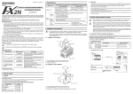
The figure below shows the shape of the system memory cassette mounting area for the
FX-20P-E main units described above.
Enlarged view
1-10
FX-20P-E Handy programming panel
Notes to Users 1
2) Version upgrade to V 3.00 or later is possible with restrictions in functionality for FX-20P-E
main units manufactured from November 1994 to July 1997 with manufacturer serial
No.s in the range from "4Y9500" to "77****".
Restricted functionality: When the model "FX2N Series" is selected in the offline mode,
the program capacity is limited to "up to 8K steps".
*1 Version upgrade to V 3.00 or later is possible with restrictions in functionality for FX-20P-E main units
manufactured from November 1994 to July 1997 with manufacturer serial No.s in the range from
"4Y9500" to "77****".
Restricted functionality: When the model "FX2N Series" is selected in the offline mode, the
program capacity is limited to "up to 8K steps".
2. How to understand the manufacturer's serial No.
Expression of manufacturer's serial No. : 4 Y
Batch number
Production Month: 1 (Jan) to 9 (Sep), X (Oct), Y (Nov) or Z (Dec)
Production Year: E.g. 1994 or 2004
1-11
FX-20P-E Handy programming panel
1.9
Notes to Users 1
Replacement of system memory cassette
When purchasing the FX-20P-E a system memory cassette is mounted.
However, only when upgrading the system version or changing the specification of the
application should the system memory cassette be replaced.
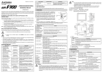
System memory cassette replacement method (Perform the steps 1) to 3) in this order.)
1 ) T h e s k id p a n t o f th e s y s te m
m e m o r y c a s s e tte is
d e p re s s e d .
2 ) P u
th e
T h
b y
ll o u t th e
d ir e c tio
e m a in b
a b o u t 1
s y
n o
o d
m m
s te m m e m o r y c a s s e tte in
f th e a rro w .
y o f F X - 2 0 P - E p u ll a w a y
.
3 ) In s e n t n e w s y s te m m e m o ry
c a s s e tte a fte r r e m o v in g th e o ld
s y s te m m e m o ry c a s s e tte .
IMPORTANT
Never touch the attachment areas on the system
memory cassette and on the FX-20P-E.
1-12
FX-20P-E Handy programming panel
1.10
Notes to Users 1
Specifications
Item
Ambient temperature
Ambient humidity
Vibration Resistance
- intermittent vibration
Vibration Resistance
- Continuous vibration
Shock Resistance
Environment
Supply voltage
Specifications
0 to 40°C
35 ~ 85% Relative Humidity, No condensation
Conforms to EN 68-2-6; 10 ~ 57 Hz: 0.075 mm Half Amplitude
57 ~ 150 Hz: 9.8 m/s2 Acceleration
Sweep Count for X, Y, Z: 10 times (80 min. in each direction)
Conforms to EN 68-2-6; 10 ~ 57 Hz: 0.035 mm Half Amplitude
57 ~ 150 Hz: 4.9 m/s2 Acceleration
Sweep Count for X, Y, Z: 10 times (80 min in each direction)
Conforms to EN 68-2-27: 147m/s2 Acceleration, Action time 11ms
3 times in each direction X, Y, and Z
Free from corrosive or flammable gas and excessive conductive dust
5V DC±5% supplied from PLC
150 mA*1
RAM: 16K steps (8K steps in FX-20P-E main units that were manufactured in July 1997 or earlier
User memory capacity
with manufacturer serial No.s "77****" or earlier)
Memory backup capacitor
Memory backup for power failure After being powered for 1 hour it can retain internal device data for 3 days without externally
supplied power
Display unit
Liquid crystal display unit with backlight
Character matrix
1 character: 40 dots (8 × 5), bottom 5 dots of each line (1 × 5 dots) are used for the prompt
Display
Number of characters 64 characters (16 characters × 4 lines)
contents
Character types
Alphanumeric
Keyboard
35 keys
PLC interface
In conformance to EIA and RS422, connected to FX Series PLC with cable FX-20P-CAB or FX-20P-CAB0.
Inbuilt
interface Extension interface
Connected to extension module
Available when dedicated module is connected (write, read, collation and deletion check)
ROM writer function
Current consumption
*1 When FX-20P-RWM is used, the current is 180mA.
1-13
FX-20P-E Handy programming panel
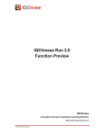
Dimensions
3 0
(1 .1 8 ")
H o ld e r h o le f 1 2 ( 0 .4 7 " )
1 2 .5
(0 .4 9 ")
Dimensions of FX-20P-E
R D
W R
IN S
D E L
M N T
T E S T
O T H E R
C L E A R
H E L P
L D
X
A N D
M
O R
Z /V
F N C
K /H
L D I
Y
A N I
S
O R I
T
°
P /I
O U T
C
A N B
D
O R B
E
E N D
F
S E T
8
P L S
9
M C
A
S T L
B
R S T
4
P L F
5
M C R
6
R E T
7
N O P
0
M P S
1
M R D
2
M P P
3
9 0 (3 .5 4 ")
T h
p o
d a
h o
h a
1 7 0 (6 .6 9 ")
1.11
Notes to Users 1
e h o o
s itio n
s h e d
o k is
n g in g
k s lid e s to th e
in d ic a te d b y
lin e s . T h e
u s e d fo r
th e H P P .
,
S P
S T E P
G O
3 0
(1 .1 8 ")
W e ig h t: A p p r o x . 0 .4 k g ( 0 .8 8 lb )
U n it: m m
( in c h )
The FX-20P-E is equipped with the program cable FX-20P-CAB (1.5 m) as standard.
The FX-20P-E-SET0 is equipped with the program cable FX-20P-CAB0 (1.5 m) as standard.
1-14
FX-20P-E Handy programming panel
2.
Startup Procedure
2.1
Startup procedure
Connect the HPP to the
PLC, power PLC ON.
Screen
display
COPYRIGHT(C)1990
MITSUBISHI
ELECTRIC CORP
MELSEC FX V4.10
2 seconds
later
PROGRAM MODE
ON LINE (PC)
OFF LINE (HPP)
Startup Procedure 2
• While the power from the PLC is OFF, connect the HPP to
the PLC.
• If the power from the PLC is turned ON while the [RD/WR]
key on the HPP is pressed, the PLC starts up in the STOP
status even if the PLC RUN input is ON, and becomes
ready for programming.
(Only FX, FX2C, FX0, FX0S and FX0N are possible)
When the power of the PLC is turned OFF once then
turned on again, the RUN status of the PLC is valid. (The
RUN status is not valid by changeover from STOP to
RUN.)
• In the initial status, the cursor is located in "ONLINE (PC)".
Select a desired program mode by pressing the [↑] or [↓]
key, then press the [GO] key to proceed to the next screen.
2-1
FX-20P-E Handy programming panel
Startup Procedure 2
From the previous page
When the
GO
online mode
is selected
When the offline
mode is selected
SELECT PC TYPE
FX, FX0
FX2N,FX1N,FX1S
GO
ON LINE MODE FX
SELECT FUNCTION
OR MODE
MEM. SETTING 8k
(p.t.o)
When the offline mode
is selected, "OFF LINE
MODE" is displayed.
• When the online mode is selected, the HPP
automatically discriminates the PLC model, and
proceeds to the function selection screen.
If the entry code has been registered in the PLC,
the HPP proceeds to the entr y code input
screen. (Refer to 10.5.4.)
• When the offline mode is selected, select the PLC
model by pressing the [↑] or [↓] key, then press
the [GO] key to proceed to the next screen.
At this time, if the selected model is different from
the stored model, the following screen appears.
1. OFF LINE MODE
EXECUTE?
OK→[GO]
NO→[CLEAR]
- Press the [GO] key to register the selected
model to the parameter (initial value), then
proceed to the mode selection screen.
- Press the [clear] key to return to the program
mode selection screen.
When using the FX 1S Series PLC, change the
program capacity to 2k steps by setting the
parameter as described later. (Refer to 10.5.3.)
2-2
FX-20P-E Handy programming panel
Startup Procedure 2
(From the previous page)
Select the
read mode.
Select the
write mode.
Select the
Select the
Select the
delete mode. monitor
test mode.
mode.
MNT/
INS/DEL
TEST
Select the
insert mode.
RD/WR
RD/WR
RD/WR
INS/DEL
INS/DEL
Refer to
chapter 4.
Refer to
chapter 5.
Refer to
chapter 6.
Refer to
chapter 7.
MNT/
TEST
Refer to
chapter 8.
MNT/
TEST
Refer to
chapter 9.
Select the
others mode.
OTHER
Refer to
chapter 10.
• Mode changeover shown above is always valid (except while an instruction or device is
input). After selecting a mode, perform the operation above again to display another mode
screen.
• Without regard to the display status of the HPP, press the [RST] and [GO] keys at the same
time to reset the HPP (and display the screen which is displayed immediately after the
power of the HPP is turned on.)
(In this case, programs and parameters which have been input in the offline mode are not
cleared.)
2-3
FX-20P-E Handy programming panel
2.2
Startup Procedure 2
Handling of FX0/FX0S/FX0N/FX1S/FX1N Series PLC
When starting up the HPP in the offline mode, select the following PLC if the FX0/FX0S/FX0N/
FX1S/FX1N Series PLC is used.
V3.00 or former
V4.00 or later
FX0/FX0S/FX0N FX, FX0
FX, FX0
FX1S
FX, FX0
FX2N, FX1N, FX1S
FX1N
FX2N
FX2N, FX1N, FX1S
When transferring unsupported element in PLC programs, an error may occur in the HPP or in
the PLC because the program capacity, instructions and device ranges have not been
supported by the chosen PLC type.
When using the FX0/FX0S/FX0N/FX1S/FX1N Series PLC, refer to 2.2.1 to 2.2.4.
2.2.1
Program
Make each program within the valid device ranges and instructions supported in the chosen
PLC. If a program containing an invalid device or unsupported instruction is transferred to the
PLC, the PLC executes the error check, and does not change to the RUN status. (If an
operation error occurs, the PLC remains in the RUN status and a corresponding instruction is
not executed.)
Especially, in the FX0/FX0S/FX0N Series PLC, application instructions cannot be used in the
form of pulse execution.
If an invalid device or instruction is written to the PLC, it is not transferred as it is, but may be
changed into an invalid instruction. At this time, a collation error occurs in the HPP, and the
message "WRITE ERROR" is displayed accordingly.
2-4
FX-20P-E Handy programming panel
2.2.2
Startup Procedure 2
Parameter settings
In parameter settings, leave the latch range, the memory capacity, the file register capacity in
the default status respectively.
1) Setting the memory capacity
a) Program capacity: Select 2k steps.
Do not select any other number of steps.
If the program capacity is set to more than 2k steps, when a program is transferred to the
PLC, the message "HPP PARA. ERROR" is displayed, and the program is not written.
When using theFX0/FX0S Series PLC, make a program of less than 800 steps.
If a program of 800 steps or more is written to the FX0/FX0S Series PLC, it is ignored and
is not written.
If the program capacity is set to 2k steps, the NOP instruction is automatically set to a
program of 800 steps or more when it is read from the FX0/FX0S Series PLC.
b) File register: Do not set the file register capacity. (only when using FX0/FX0S)
If the file register capacity is set, when a program is written to the FX0/FX0S Series PLC,
the message "WRITE ERROR" is displayed, and the program is not written.
2) Setting the latch range
The latch range cannot be changed in the FX0/FX0S/FX0N/FX1S/FX1N Series PLC.
If the latch range is set (changed), when a program is written to the FX0/FX0S/FX0N/FX1S/
FX1N Series PLC, the message "COMPLETED" is displayed. Though the program is written,
the PLC ignores the set latch range.
3) Registering the entry code
The entry code can be registered.
2-5
FX-20P-E Handy programming panel
2.2.3
Startup Procedure 2
Constant changes in run status
Even if the program memory is held in the EEPROM, constants (set values and present values
of timers, counters and data registers) can be changed in the RUN status of the FX0/FX0S/
FX0N/FX1S/FX1N Series PLC. However, when a constant is changed, the scan time of the PLC
increases by 20 to 30 ms, and the response delay (by 20 to 30 ms) is generated in the input
interrupt "I 00 to I 30".
2.2.4
FX-20P-E
When a program is transferred while the offline mode is selected in the FX-20P-E, "HPP→FX-RAM"
or "HPP←FX-RAM" is displayed even if the program memory is held in the EEPROM.
2-6
FX-20P-E Handy programming panel
3.
Outline of Programming
3.1
Outline of programming
Outline of Programming 3
In the HPP, create a program by using the instruction list and manipulating the keyboard.
The destination to write a created program is different between the online mode and the offline mode.
In the online mode, a program is directly written to the program memory in the PLC. In the
offline mode, a program is written to the inbuilt HPP RAM.
When operating the PLC with a program created in the offline mode, the program should be
transferred from the HPP to the PLC.
While the PLC is in the RUN status, a program cannot be written or changed from the HPP.
Make sure to set the PLC to the STOP status, then write or change a program from the HPP.
3.2
Functions used in programming
[Read] ..........Reads a created program from the program memory, and displays it.
By specifying the step No., instruction, device or pointer, an arbitrary position of
the program can be displayed.
[Write] ...........Writes a new program or overwrites an existing program for modification or addition.
[Insert]..........Inserts an instruction to an existing program and carries down later step No’s.
[Delete] ........Deletes a specified instruction from an existing program and carries up later step
No’s.
An instruction or pointer can be deleted. Batch deletion and deletion of specified
ranges via the NOP instruction are also available.
• Press the [HELP] key during programming to display the valid program step range.
Press the [HELP] key again to reset the help display.
However, if the [HELP] key is pressed immediately after the [FNC] key, search of an
application instruction is started or interrupted.
3-1
FX-20P-E Handy programming panel
3.3
Program modes
3.3.1
Online mode
Outline of Programming 3
HPP
PLC
In the online mode, the HPP directly accesses
Programming
Key
Inbuilt
the program memory in the PLC.
operation Read Write
memory
However, write is disabled if the write protect
Transfer
switch on the EEPROM memory cassette is ON
Inbuilt
Memory
or if the PLC is currently in RUN status.
RAM
cassette
Write
1) If a memory cassette is not attached to the
PLC, programs are written to the inbuilt PLC
memory. If a memory cassette is attached to the PLC, programs are written to the memory
cassette.
2) By operation from the HPP, programs can be transferred between the inbuilt PLC memory
and a memory cassette attached to the PLC.
3.3.2
Offline mode
In the offline mode, the HPP accesses it own inbuilt RAM.
Programs written to the inbuilt HPP RAM can be batch-transferred to the inbuilt PLC RAM or a
memory cassette attached to the PLC. Transferring to the ROM writer (option) is executed also
in the offline mode.
1) Programming in the offline mode is executed to the inbuilt HPP RAM regardless of the
program memory type in and the RUN/STOP status of the PLC.
3-2
FX-20P-E Handy programming panel
Outline of Programming 3
2) The following condition is required to execute batch transfer to the PLC.
RUN/STOP status of PLC
Program memory in PLC
STOP
RAM, EEPROM *
RUN/STOP
RAM, EEPROM, EPROM
Write from HPP to PLC
Read from PLC to HPP
Collation between HPP and PLC
*The write-protect switch should be OFF.
Inbuilt HPP RAM
In the offline mode, programming is executed to the inbuilt HPP RAM.
Even if programming is executed to another PLC in the online mode by using the HPP
programmed in the offline mode, programs saved in the HPP remain saved as they are.
However, if programs are read and transferred from the PLC to the HPP in the offline mode,
programs saved in the HPP are erased.
Capacitor function
The inbuilt HPP RAM is backed up against power failure by the large capacitor.
(With power supply for 1 hour, the RAM is backed up for 3 days.)
Accordingly, programs can be transferred and written to another PLC from the HPP in which
programs have been entered in the offline mode.
3-3
FX-20P-E Handy programming panel
3.4
Outline of Programming 3
Types of program memories
Memory cassette
(for the FX0N/FX/
FX2C/FX2N
Memory board Memory cassette
(for the FX2NC (for the FX1S/
Series PLC)
FX1N Series PLC)
F X
F X
2 N C
2 N C
-E E P R O M -4 C
-E E P R O M -1 6 (C )
F X
1 N
W R
-E E P R O M -8 L
8 L ®
P L C
FX-RAM-8
O N
P R O T E C T
S W
O F F
R D
8 L ¬
P L C
FX-EEPROM-4
FX-EEPROM-8
FX-EEPROM-16
FX-EPROM-8
Write-protect switch
O N
F
O F
M e m o ry c a s s e tte
O N
O N
F
O F
M e m o ry b o a rd
F
O F
M e m o ry c a s s e tte
• RAM (random access memory)
The RAM can be read and written at any time. Because the
saved contents are erased by power failure, the RAM should
be backed up by the battery. And the saved contents are
erased also when the RAM is removed from the PLC.
The RAM is used also as the internal memory of the HPP
and the PLC.
• EEPROM (electrically erasable programmable read only
memory)
The EEPROM is read only memory (ROM), and can be
written at any time by applying a specified voltage.
The saved contents are kept saved against power failure.
The total number of allowable write occasions is restricted
by the life expectancy. The life expectancy is 10,000 times
for memory cassettes and memory boards, and 20,000
times for the EEPROM built in the PLC. The write-protect
switch is provided to prevent erroneous write.
• EPROM (erasable programmable read only memory)
The EPROM is read only memory. The saved contents are
erased by irradiation of ultraviolet rays.
After all saved contents are erased, new contents can be
batch-written by the ROM writer.
• The saved contents are kept saved against power failure.
• Even if the EEPROM and the EPROM are attached to the
PLC, a dedicated battery or large capacitor is required to
back up the image memory.
3-4
FX-20P-E Handy programming panel
Read 4
4.
Read
4.1
Outline of read operation
When the online mode is selected, programs written to the memory of the PLC (or the memory
cassette if it is attached) are displayed in the HPP.
When the offline mode is selected, programs written in the inbuilt HPP RAM itself are displayed
in the HPP.
Read operation condition
PLC
status
4.2
RUN:✓
STOP:✓
Valid memory
Inbuilt memory:✓
RAM cassette:✓
EEPROM
cassette:✓
EPROM
cassette:✓
Read by step No.
• Four lines of program are read and displayed from an instruction at the specified step No.
• If the specified step No. corresponds to an operand such as a set value of a timer or
counter, four lines are read and displayed from the instruction of the operand.
• Press the [GO] key again to scroll the screen display to the fifth line and later of the
displayed instruction.
• Use the cursor control keys to scroll lines one by one.
Basic operation
Read
function
STEP
Specify the step No.
GO
Execute read.
4-1
FX-20P-E Handy programming panel
Read 4
Example: Reading the step No. 55
Display example
In the step 2)
R
5 ORB
6 AND M 100
7 OUT Y 001
55
STEP
In the step 4)
R
55 LD
56 OR
57 ORI
58 OUT
X 004
X 006
M 102
Y 035
Key operation
1) Read function
2)
STEP
3)
5
4)
GO
5
4-2
FX-20P-E Handy programming panel
4.3
Read 4
Read by instruction
• For an application instruction, press the [FNC] key and input the FNC No.
in the way "[FNC][D][1][2][GO]", "[FNC][1][2][GO]" etc. Both instructions are searched
regardless to input of the pulse symbol "P".
• The specified instruction word is searched from the step No. 0 in turn, and four lines are
displayed on the screen from the first found instruction.
• Press the [GO] key again to search for the instruction with the same condition from the next
step of the currently found step.
• If all specified instruction words have been found or if a specified instruction word is not
found at all, the message "NOT FOUND" is displayed. Program lines after the END
instruction are not displayed.
• Use the cursor control keys to read the program step by step. The cursor keys function in
the same way even while the program is read by pointer or device mode.
Basic operation
Search again
Read
function
Instruction
Instruction not requiring device or
application instruction
Device
symbol
Device
No.
GO
Read the
program step
by step.
Instruction requiring a device
4-3
FX-20P-E Handy programming panel
Read 4
Example: Reading "PLS M104"
Display example
In the step 3)
R 100 AND
101 OR
102 OUT
PLS
INSTR
M 125
Y 013
Y 010
M 104
Key operation
1) Read function
2)
PLS
3) M
4)
1
0
4
GO
4-4
FX-20P-E Handy programming panel
4.4
Read 4
Read by pointer
• Four lines are read and displayed from the specified label.
• If the specified label is not found, the message "NOT FOUND" is displayed. Program lines
after the END instruction are not read.
• Read by pointer reads interrupt pointers and labels. Pointers specified as operands in
application instructions are not searched.
Basic operation
Search again
Read
function
P
I
Specify the pointer
No.
GO
Read the program
step by step.
• Pointer (P)
Number in the CJ or CALL instruction which specifies a jump destination label No.
• Label (P)
Number of a quick reference title indicating the head of a jump destination specified
by the pointer No.
• Interrupt pointer (I)
Added at the top of an interrupt program. At the end of an interrupt program, "IRET
(interrupt return instruction)" is added.
4-5
FX-20P-E Handy programming panel
Read 4
Example: Reading label of the pointer No. 3
Display example
In the step 2)
R
50 AND
51 SET
52 LD
POINTER
M 123
Y 010
X 012
P 3
In the step 3)
R 102
P 3
103 LDI M 100
104 MPS
105 AND X 012
Key operation
1) Read function
2)
3)
P
3
GO
4-6
FX-20P-E Handy programming panel
4.5
Read 4
Read by device
• The specified device is searched from the step No. 0 in turn, and four lines of program are
displayed from the first found instruction.
• Press the [GO] key again to search the device of the same condition from the next step of
the currently found step.
• If all specified devices have not been found consequentially, the message "NOT FOUND" is
displayed. Program lines after the END instruction are not read.
Basic operation
Search again
Read
function
'
SP
Device
symbol
Device
No.
GO
Read the program
step by step.
4-7
FX-20P-E Handy programming panel
Read 4
Example: Reading "Y123"
Display example
In the step 2)
10 LD
R
11 AND
13 ORI
DEVICE
X 002
M 003
X 003
Y 123
In the step 4)
R
53 OUT Y 123
54 LD X 011
55 OUT C 12
K 60
*
R
Key operation
1) Read function
2)
S'P
3)
Y
4)
1
2
3
GO
GO
124 AND Y 123
MPS
* Press the [GO] key again to search "Y123"
from the next step.
• When the program is read by device, only devices X, Y, M, S, T, C, D, V and Z of basic
instructions are searched. However, if D is searched, V and Z used after the OUT
instruction of timers and counters are not searched.
4-8
FX-20P-E Handy programming panel
Write 5
5.
Write
5.1
Outline of write operation
Programs are written to the memory inside the PLC when the online mode is selected, and to the inbuilt HPP
RAM when the offline mode is selected.
When the online mode is selected, if a memory cassette (except the EPROM) is attached to the PLC,
programs are written to the memory cassette. (When using the EEPROM, set the write-protect switch to OFF.)
Programs can only be written while the PLC is in STOP mode.
New programs can be written, and existing programs can be overwritten for modification.
When writing a new program, input instructions from the step No. 0 in turn. When overwriting an existing
program for modification, put the cursor on a position to be modified, then input an instruction.
Item
Writing a new program
Key operation for function selection
RD/
WR
RD/
WR
Write a new program from step 0.
Read a program to be modified, and display
it in the display unit.
RD/
WR
Overwriting an
existing program for
modification
Read an
instruction
to be
modified.
Description
RD/
WR
Modify or add instructions.
INS/
DEL
Insert instructions.
INS/
DEL
INS/
DEL
Delete unnecessary portions of the
program.
5-1
FX-20P-E Handy programming panel
Write 5
Write operation condition
PLC
status
RUN:×
STOP:✓
Valid memory
Inbuilt memory:✓
RAM cassette:✓
EEPROM
cassette:U
EPROM
cassette:×
• When using the EEPROM memory cassette, set the write-protect switch to OFF.
5.2
Input of basic instruction
• Basic instructions are classified into those which are input individually such as "ORB" and
"MPS", those which are input together with a device such as "LD X000" and "AND M0" and
those which are input together with a device (first device) and set value (second device).
Basic operation
Write
function
Instruction
GO
Write
function
Instruction
Device
symbol
Write
function
Instruction
Input requiring only an instruction
Device
symbol
Device
No.
Device
No.
First device
GO
'
SP
Input requiring an instruction and device
Device
symbol
Device
No.
GO
Input requiring an
instruction, first
device and
second device
Second device
5-2
FX-20P-E Handy programming panel
Write 5
Example: Entering the ORB instruction
Display example
In the step 3)
W
4 LDI X 004
5 AND X 005
6 ORB
7 NOP
Key operation
1) Write function
2) ORB
3)
GO
Instruction words are entered individually:
ANB, ORB, MPS, MRD, MPP, RET, END and NOP
Example: Entering "LD X0"
Display example (before determined)
Key operation
In the step 3)
1) Write function
W
0 LD X 000
1 NOP
Instruction words which are entered together with
2 NOP
2) LD
a device:
3 NOP
3) X
0
LD, LDI, AND, ANI, OR, ORI, SET, PLS, PLF,
Display example
MCR, STL and OUT (excluding T and C)
(after determined)
4) GO
In the step 4)
- When the MCR instruction is entered, the
W
0 LD X 000
nesting level symbol "N" is automatically
1 NOP
displayed.
2 NOP
3 NOP
• While the HPP is waiting for input of a device symbol or device No., the prompt is displayed
at the end of the input position.
5-3
FX-20P-E Handy programming panel
Write 5
Contact instructions other than LD, LDI, AND, ANI, OR an ORI (Ver 4.00 and later)
Instruction
Key operation
LDP
[LD] [P/I]→[Device symbol] [Device No.]→[GO]
LDF
[LD] [F]→[Device symbol] [Device No.]→[GO]
ANDP
[AND] [P/I]→[Device symbol] [Device No.]→[GO]
ANDF
[AND] [F]→[Device symbol] [Device No.]→[GO]
ORP
[OR] [P/I]→[Device symbol] [Device No.]→[GO]
ORF
[OR] [F]→[Device symbol] [Device No.]→[GO]
INV
[NOP] [P/I]→[GO]
Comparison
Comparison contact instructions can be entered in the same way as application
contact instruction instructions. Refer to 5.3.
5-4
FX-20P-E Handy programming panel
Write 5
Example: Entering "OUT T100 K19"
Display example
In the step 6)
W 100 OUT M 100
101 OUT T 100
K 19
104 NOP
Key operation
1) Write function
2)
OUT
3)
T
4)
5)
6)
1
0
1
9
0
S'P
K
GO
Instruction words which are entered together with
first device and second device:
MC and OUT (T, C)
-
When the MCR instruction is entered, the
nesting level symbol "N" is automatically
displayed.
• While the HPP is waiting for input of a device symbol or device No., the prompt is displayed.
• The allowable device No. range varies depending on the PLC model. While a program is
entered, the device range is checked.
5-5
FX-20P-E Handy programming panel
5.3
Write 5
Write of application instruction
When entering an application instruction, press the [FNC] key first, then input the instruction No.
When entering the instruction No., directly input a desired No. or display the instruction symbol
list by using the help function, search and find a desired instruction, then input it. If the
instruction No. is not clear, use the help function.
Basic operation
Write
1) function
FNC
(16-bit
instruction)
Application
instruction No.
GO
P
'
SP
D
(32-bit instruction = double)
Write
2) function
FNC
(16-bit
instruction)
Device
symbol
Device
No.
Pulse
10's digit of
application instruction
HELP
1's digit of application
instruction
D
GO
(32-bit instruction = double)
P
'
SP
Device
symbol
Device
No.
Pulse
5-6
FX-20P-E Handy programming panel
Write 5
• What is an operand?
Operands are devices used for operations of instructions.
For example, in the case of MOV instruction,
[ MOV D0 D1 ]
Operand
When entering an operand, make sure to input it in the order "[S’P] (operand)".
'
SP
Device
symbol
Device
No.
Operand
• Timing to specify the D (double)/P (pulse) instruction Specification of the D/P instruction is
valid if it is executed in the same order as the display (operation example 1) or if it is
executed after input of the instruction No.
Either D and P can be specified first or the operator can press the [HELP] key to display the
instruction word list, check whether D and P can be specified for the instruction, then
specify D and P.
• Restriction in programming when the FX/FX2C Series PLC is used
When a RAM file register is used as an operand, only the BMOV instruction is available.
5-7
FX-20P-E Handy programming panel
Write 5
Example: Input by FNC No. (example of "[D]MOV[P] D0 D2")
Display example
In the step 9)
W 200 DMOVP
D
0
D
2
209 NOP
Key operation
1) Write function
2)
6) D
FNC
7)
3) D
1
S'P
2
8) D
4)
2
P
9)
5)
0
GO
S'P
• Using the ASC instruction, ASCII characters can only be read and not written. For writing
ASCII characters, use the software A6GPP/A6PHP.
• An error will occur if an application instruction is not supported in the used PLC.
• Press the [FNC] and [HELP] keys in this order to display classified items of application
instructions on screen. These classification items 0 to 24 are set on seven screens, and the
screens can be scrolled by the cursor control keys.
• Among the classified items, select a desired item by using the number keys. Input a number
in the order "100’s digit, 10’s digit and 1’s digit". When the 10’s digit is entered, instructions
whose 10’s digit is the input number are displayed on the screen.
Only application instructions valid in the used PLC are displayed in the list.
Scroll the screens by using the cursor control keys, then entered a number for the 1’s digit.
By the operation above, the application instruction No. is specified.
Then, input an operand consecutively.
5-8
FX-20P-E Handy programming panel
Write 5
Example: Input from the instruction list offered by the help function
(example of "DMOVP D0 D2")
Display example
In the step 3)
0 PROGRAM FLOW
1 TRANSFERS, COMP
2 + - × ÷ , LOGICS
3 ROTATION, SHIFT
In the step 4)
10:CMP
11:ZCP
Key operation
1) Write function
2)
8)
S'P
FNC
9) D
*1
0
3) HELP
10) S'P
12:MOV
13:SMOV
4)
1
11) D
5)
14:CML
*2
In the step 11)
W
200
DMOVP 12
D
0
D
2
NOP
200
2
2
12) GO
6) D
7)
P
*1 Classified items of application instructions
0 PROGRAM FLOW
1 TRANSFERS, COMP
2 + - × ÷, LOGICS
3 ROTATION, SHIFT
4 DATA OPERATION
5 HIGH SPEED
6 HANDY INSTR.
7 FX I/O DEVICES
8 FX SER DEVICES
9 F2 UNITS
*2 Contents shown in the application instruction symbol list
Classified item No. (10's
digit of the instruction No.)
10:CMP
11:ZCP
12:MOV
13:SMOV
Instruction symbol
Validity of D/P
Double instruction is valid.
14:CML
Pulse instruction is valid.
As to points between the classified item No. and the instruction
symbol, the upper one indicates validity of D (double) instruction,
and the lower one indicates validity of P (pulse) instruction.
5-9
FX-20P-E Handy programming panel
5.4
Write 5
Input of label (P, I)
When using a P (pointer) or I (interrupt pointer) in a sequence program as a label, enter in the
same way as instructions.
Basic operation
Write
function
P
I
Pointer
No.
GO
Example 1: When entering the label No. 3
Display example
In the step 4)
W 100
P 3
101 NOP
102 NOP
103 NOP
Key operation
1) Write function
2)
P
3)
3
4)
GO
5-10
FX-20P-E Handy programming panel
5.5
Write 5
Input of number
• When numbers are entered, each number is shifted to the upper digit in turn in the display.
Accordingly, if numbers are input beyond the displayable digits, numbers input so far are
deleted from the display screen from the oldest one in turn.
When the device symbol is X or Y, if an input numeric value is less than 3 digits, "0" is
displayed in the higher digits.
• Only numbers displayed on the screen are registered. Check the displayed numbers
carefully while inputting a numeric value.
Example 1: When pressing the [1], [2], [3], [4] and [5] keys for input to the four-digit display area
12
1234
2345
12
34
5
5-11
FX-20P-E Handy programming panel
5.6
Write 5
Batch write of NOP (program all clear)
• Write the NOP (no processing) instruction to a certain or the entire range of program.
If a program already exists, it is overwritten by the NOP instruction.
In the PLC, write of the NOP instruction functions as if the program in the specified range is
deleted.
Basic operation
When specifying a
certain range
Write
function
↑
↓
NOP
Specify the start step.
K
GO Specified
range
Specify the end step No.
NOP
When specifying
the entire range
(program all clear)
End step No.
A
GO
Entire
GO range
Specify the entire range.
• When executing program all clear, programs and parameters (including the entry code) are
deleted (if the entry code has been input and accepted).
5-12
FX-20P-E Handy programming panel
5.6.1
Write 5
Batch write of NOP to specified range
Example: Batch-writing the NOP instruction in the range from the step No. 1014 to the step
No. 1024
Display example
In the step 4)
W
1012
1013
1014
1015
ANI X 013
OUT M 15
NOPK 1024
OR M1000
In the step 5)
W
1014
1015
1016
1017
NOP
NOP
NOP
NOP
Key operation
1) Write function
2)
↑
3)
NOP
4)
K
5)
(Press these keys to move the cursor to the
step No. 1014.)
↓
1
0
2
4
GO
• Move the cursor to the start step from which the NOP instruction is to be written. At this
time, write is disabled in lines without the step No.
• If a specified end step No. is a jump No., the end of the instruction is registered as the end
step.
5-13
FX-20P-E Handy programming panel
5.6.2
Write 5
Write NOP to entire range (program all clear)
Example: Entire range
Display example
In the step 3)
W
100
101
102
103
NOPA _
AND M1010
OR T 15
OUT Y 012
In the step 4)
All clear?
OK→[GO]
NO→[Clear]
Key operation
1) Write function
2)
NOP
3)
A
4)
GO
5)
GO
In the step 5)
W
0
1
2
NOP
NOP
NOP
• After the write function is set, consecutively press the [NOP] and [A] keys. At this time, the
cursor position has nothing to do with the write range.
• When the [GO] key is pressed, the message for confirming all clear is displayed.
Press the [GO] key in accordance with the message to execute batch write of NOP to the
entire range (program all clear).
When execution is completed, the cursor moves to the step No. 0.
5-14
FX-20P-E Handy programming panel
Write 5
IMPORTANT
As soon as batch write of the NOP instruction to the entire range is completed, parameter
values before execution are returned to the default values, and the latch is cleared.
Accordingly, the comment area becomes 0 block, and the file register becomes 0 block also.
(The memory capacity becomes the default value (2k or 8k steps) in accordance with the PLC
model.) However, in the online mode while a memory cassette is attached, the situation is
determined by the memory cassette capacity. And the entry code is deleted (if the entry code
has been input and accepted).
• The following devices can be backed up (latched) against power failure in the FX Series
PLC.
1) M (Auxiliary relays)
2) S (States)
3) T (Timers)
4) C (16-bit counters)
5) C (32-bit counters)
6) D (Data registers)
7) D (File registers)
5-15
FX-20P-E Handy programming panel
5.7
Write 5
Modification method (before/after determination)
A input program can be modified before determination (before the [GO] key is pressed) or after
determination (after the [GO] key is pressed.)
Before determination, press the [CLEAR] key, then enter the correct contents again from an
instruction. After determination, move the cursor to a line to be modified, then enter the correct
contents.
Example 1: Modifying "K10" to "D9" in the "OUT T0 K10" instruction (before determination)
Display example
In the step 5)
W
7 OUT T 0
K 10
10 NOP
11 NOP
In the step 8)
W
7 OUT T 0
D 9
10 NOP
11 NOP
Key operation
1) Write function
2)
6) CLEAR
OUT
7) D
3)
T
0
8)
4)
5)
9
GO
S'P
K
1
0
• Press the [CLEAR] key once to cancel the second device.
• Press the [CLEAR] key twice to modify the contents from the step No. 7.
5-16
FX-20P-E Handy programming panel
Write 5
Example 2: Modifying "K10" to "D9" in the "OUT T0 K10" instruction (after determination)
Display example
In the step 6)
W
7 OUT T 0
K 10
10 NOP
11 NOP
In the step 9)
W
7 OUT T 0
D 9
10 NOP
11 NOP
Key operation
1) Write function
2)
6)
OUT
7)
3)
T
GO
↑
0
8) D
4)
9
S'P
9)
5) K
1
GO
0
5-17
FX-20P-E Handy programming panel
Write 5
Reading a program, then overwriting a specified step in the unit of instruction
Example: Overwriting the OUT instruction in the step No. 100 with "T50" and "K123"
Display example
In the step 4)
R 100 OUT
101 LDI
102 AND
103 AND
M1010
X 013
M 124
M 125
Key operation
1) Read function
2) STEP
3)
1
T 50
X 013
M 124
M 125
4)
GO
In the step 9)
W 100 OUT T 50
K
123
101 LDI X 013
102 AND M 124
6)
OUT
7)
T
In the step 7)
W 100 OUT
101 LDI
102 AND
103 AND
In the step 10)
W 100 OUT T 50
K 123
103 LDI X 013
104 AND M 124
0
0
5) RD/WR
8)
9)
5
0
1
2
S'P
K
3
10) GO
• Set values of timers and counters that can be changed by using the monitor function.
(Refer to 2.9.)
• When consecutively overwriting an instruction or pointer near the currently read program,
directly move the line cursor to a position to be overwritten.
5-18
FX-20P-E Handy programming panel
Write 5
• Handling of the step No. during overwriting
If the number of instruction or pointer steps is different between before overwriting and after
overwriting, perform the following processing and overwrite the step No. also.
In the case of NOP, overwrite only NOP.
OUT T0
K100
11 OUT Y001
12 LD X010
13 AND M100
11 OUT T 0
K100
14 LD
OUT T0
K100
20 NOP
21 NOP
22 LD X010
23 ANI M100
X010
20 OUT T 0
K100
23 LD
X010
5-19
FX-20P-E Handy programming panel
Write 5
Modification example of instruction accompanied by an operand
• What is an operand?
Operands are devices used for operations of instructions.
For example, in the case of MOV instruction,
[ MOV D0 D1 ]
Operand
When inputting an operand, make sure to input it in the order "[S’P] (operand)".
'
SP
Device
symbol
Device
No.
Operand
Basic operation
Write
function
CLEAR
CLEAR
Instruction
word
Device
symbol
CLEAR
Device
No.
(Modification before determination)
GO
(After the second device, cancel
each device input.)
(Modification after determination)
5-20
FX-20P-E Handy programming panel
5.8
Write 5
Modification of device
Basic operation
Write
function
↑
↓
When not specifying
the digit
Device
symbol
Device
No.
GO
Z
K
V
Numeric
value
When specifying
the digit
Index decoration
When the device is Z or V
• One to eight digits can be specified.
One digit uses 4 bits, and 8 digits use 32 bits.
• "Z" and "V" indicate index registers.
An index register is added to a device to decorate the device No.
5-21
FX-20P-E Handy programming panel
Write 5
Overwriting only a specified instruction device
Example:Modifying the device K2 (digit specification) in the MOVP instruction in the step No.
100 from "X100" to "K1X0"
Display example
In the step 6)
R 100 MOVP
K2X 100
D
1
105 LD X 010
In the step 8)
W 100 MOVP
K1X 000
D
1
105 LD X 010
Key operation
1) Read function
5) RD/WR
2) STEP
6)
3)
4)
1
0
(Put the cursor on a numeric value
to be modified.)
↓
0
7) K
1
8) X
0
GO
9)
GO
• Only lines without the step No. can be modified.
(If a line with the step No. is to be modified, write it by instruction.)
• When specifying the digit, press the [K] key first, then input a numeric value.
5-22
FX-20P-E Handy programming panel
Program Insert Operation 6
6.
Program Insert Operation
6.1
Outline of insert operation
Read a program, and insert an instruction or pointer in a specified position.
An instruction or pointer is inserted in a position above the step specified by the cursor. (Lines not
displaying the step No. cannot be specified.)
After the inserted position, each step No. is automatically carried up. (The display is shifted down.)
When inserting an instruction or pointer near the currently read program, directly move the line
cursor to a desired position.
Basic operation
Insert an instruction.
Read
program.
INS/
DEL
Instruction
word
GO
Device
symbol
Insert
function
Device
No.
Specify the first device.
P
I
'
SP
Device
symbol
Device
No.
Specify the second and later
devices.
Pointer/Interrupt
No.
Specify a pointer/Interrupt No.
• Cautions on inserting an instruction
If an instruction is inserted while the program memory is full and has no free space, an error
message is displayed and insert is not executed.
6-1
FX-20P-E Handy programming panel
Program Insert Operation 6
Insert operation condition
PLC
status
RUN:×
STOP:✓
Valid memory
Inbuilt memory:✓
RAM cassette:✓
EEPROM
cassette:U
EPROM
cassette:×
• While the PLC is in the RUN status or while the EPROM cassette is attached, the insertion
operation is disabled (in the online mode.)
Example: Inserting the AND instruction M5 before the step No. 200
Display example
In the step 4)
I
200 AND
201 OR
202 OUT
203 LD
In the step 7)
I
200 AND
200 AND
201 OR
202 OUT
T 111
C 25
Y 100
X 002
M 5
T 111
C 25
Y 100
Key operation
1) Read function
2) STEP
3)
2
4)
GO
In the step 8)
I
200 AND
201 AND
202 OR
203 OUT
0
5) INS/DEL
6)
GO
0
AND
7) M
8)
5
GO
M 5
T 111
C 25
Y 100
6-2
FX-20P-E Handy programming panel
Program Delete Operation 7
7.
Program Delete Operation
7.1
Outline of delete operation
Read a program, and delete an instruction, pointer or NOP.
Delete operation condition
PLC
status
•
7.2
RUN:×
STOP:✓
Valid memory
Inbuilt memory:✓
RAM cassette:✓
EEPROM
cassette:U
EPROM
cassette:×
While the PLC is in the RUN status or while the EPROM cassette is attached, the delete
operation is disabled.
Delete of instruction and pointer
Basic operation
Move the cursor.
Read
program.
INS/
DEL
INS/
DEL
GO
Delete function
•
•
By the operation above, the instruction in the cursor position is deleted.
As to instructions which use two or more lines such as set values of timers and counters and
operands of application instructions, when the instruction part, set value or operand is deleted,
all lines are deleted at a time.
After the deleted position, each step No. is automatically carried down. (The display is shifted up.)
7-1
FX-20P-E Handy programming panel
Program Delete Operation 7
Example: Deleting "AND M10" in the step No. 100
Display example
In the step 6)
D 100 AND
101 ANI
102 OR
103 OUT
In the step 7)
D 100 ANI
101 OR
102 OUT
103 LD
M 10
M 11
M 12
Y 0
M 11
M 12
Y 0
M 20
Key operation
1) Read function
2) STEP
3)
1
4)
GO
0
0
5) INS/DEL
Select the delete function.
6) INS/DEL
7)
GO
7-2
FX-20P-E Handy programming panel
7.3
Program Delete Operation 7
Batch delete of program by specifying range to be deleted
• The range of the program specified by step Nos. is deleted.
• If an instruction in the specified start step No. uses two or more lines, the head of the
instruction is regarded as the start step. If an instruction in the specified end step No. uses
two or more lines, the end of the instruction is regarded as the end step.
(In the example below, the end step No. is regarded as "42", not "40".)
• On the screen after the specified range is deleted, deleted steps are eliminated, and the
program is displayed from the deleted start step.
Basic operation
Read
program.
INS/
DEL
INS/
DEL
Delete function
STEP
Step No.
Specify the start step No.
'
SP
STEP
Step No.
GO
Specify the end step No.
7-3
FX-20P-E Handy programming panel
Program Delete Operation 7
Example: Deleting the range from the step No. 10 to the step No. 40
Display example
In the step 4)
D
40 OUT T 10
K50
43 LDI X 005
10
STEP
In the step 7)
D
40 OUT T 10
K50
43 LDI X 005
RANGE 10
40
In the step 8)
D
10 LDI
11 AND
12 LD
13 AND
7.4
Key operation
1) INS/DEL
Deletion function
2) INS/DEL
3) STEP
4)
1
0
5)
S'P
6) STEP
X 005
M 10
Y 006
M 115
7)
4
0
8)
GO
Batch delete of NOP instructions
Basic operation
Read
program.
INS/
DEL
INS/
DEL
Delete function
•
NOP
GO
Batch-delete NOP
instructions.
All NOP instructions existing from step No. 0 to the final instruction (except the NOP instruction)
are deleted at a time. After batch delete of NOP instructions, each step No. is automatically
carried down. (The display is shifted up.)
7-4
FX-20P-E Handy programming panel
Monitor 8
8.
Monitor
8.1
Outline of monitor operation
Display the PLC operation status on the HPP. (The monitor operation is available even while
the PLC is in the STOP status.)
The monitor operation is valid only while the online mode is selected.
(If the offline mode is selected when the HPP started up, it can be changed over to the online
mode by using the others function.)
Monitor operation condition
PLC
status
8.2
RUN:✓
STOP:✓
Valid memory
Inbuilt memory:✓
RAM cassette:✓
EEPROM
cassette:✓
EPROM
cassette:✓
List program monitor
• In the list program monitor, the list program is displayed and the status of contacts and coil
driving are indicated.
• In conductive contacts and operating coils, "" is added after the instruction.
8-1
FX-20P-E Handy programming panel
Monitor 8
Basic operation
Read
program.
MNT/
TEST
STEP
Monitor
function
Input a
step No.
GO
Input an
instruction and
first device.
Read a program to be displayed.
Example: Monitoring step No. 126
Display example
In the step 4)
M 126 LD
127 ORI
128 OUT
129 LDI
The contact is
conductive.
Key operation
1) Monitor function
X 013
M 100
Y 005
2) STEP
T 15
3) 1 2 6
The coil is
operating.
4) GO
8-2
FX-20P-E Handy programming panel
8.3
Monitor 8
Device monitor
•
•
•
Specify and display a device to be monitored.
As to bit devices (X, Y, M and S), the ON/OFF status is displayed. As to timers (T) and counters (C),
the present value and the set value are displayed.
As to data registers (D) and index registers (V and Z), the present value is displayed.
In the display of word devices (T, C, D, V and Z), press the [help] key to change over the format
between decimal and hexadecimal.
Basic operation
Monitor
function
'
SP
Device
No.
Device
No.
D
In the case of V or Z
GO
Display the
previous
device No.
Display the
next device
No.
Specify "32 bits".
Example: Monitoring device X000
Display example
In the step 4)
M
X 000
Key operation
1) Monitor function
2)
3)
4)
S'P
X
0
GO
8-3
FX-20P-E Handy programming panel
Monitor 8
Example: Monitoring device T0
Display example
In the step 4)
M TO
K 100
PR
K 250
Decimal display
In hexadecimal display,
"H" is displayed.
Present value
Key operation
1) Monitor function
2)
Set value
3)
The ON status of the
reset coil is monitored.
4)
S'P
T
0
GO
The OFF status of the output
contact is monitored.
• When the set value is indirectly specified through a data register (D), the data register No.
and the present value of the data register are displayed as the set value.
Display example
When the set value is indirectly specified
M TO
K 100
Data register No.
PR
D 0
K 250
Present value of data register
8-4
FX-20P-E Handy programming panel
8.4
Monitor 8
Operation state monitor
• While a step ladder type program is running in the PLC, up to eight operating states are
displayed.
• As the state changes, displayed No’s. automatically proceed to indicate the operation
process of the machine.
• Only the state in the range from S0 to S899 can be monitored. S900 and later (for
annunciators) are ignored.
• Before executing the operation state monitor, set M8047 (STL monitor valid) to ON in the
PLC.
Basic operation
Monitor
function
STL
GO
Execute the operation state monitor.
Display example
Operation state monitor
M ACTIVE STATE
S 30 S 41 S 52
S 63 S 73 S 82
S 91 S 104
When M8047 (STL monitor valid) is OFF
M ACTIVE STATE
M8047 IS NOT ON
8-5
FX-20P-E Handy programming panel
Monitor 8
Monitoring annunciators
Monitor
function
'
SP
D
M
8
0
4
9
GO
If M8049 is set to ON, the smallest No. of operating ones among S900 to S999 can be
monitored by the operation above.
8-6
FX-20P-E Handy programming panel
9.
Test 9
Test
Caution on operation
Thoroughly read the manual and sufficiently assure safety before executing the operation to
forcibly set devices to ON/OFF or the operation to change present values and set values of
word devices in the test mode.
Otherwise, the machine may be damaged and accidents may occur by erroneous operations.
9.1
Outline of test function
In the test mode, devices in the PLC can be forcibly set to ON/OFF, present values of word
devices (T, C, D, Z and V) in the PLC can be changed, and set values of timers (T) and
counters (C) in the PLC can be changed from the HPP.
Perform the device monitor operation to display devices in the PLC to be changed.
Test operation condition
PLC
status
RUN:✓
STOP:✓
Valid memory
Inbuilt memory:✓
RAM cassette:✓
EEPROM
cassette:U
EPROM
cassette:U
• While the EPROM is attached to the PLC, set values of timers and counters cannot be
changed.
While the EEPROM is attached to the PLC and the PLC is in the RUN status, set values of
timers and counters cannot be changed.
9-1
FX-20P-E Handy programming panel
9.2
Test 9
Forcible setting of devices to ON/OFF
• From the HPP, forcibly set devices in the PLC to ON or OFF.
• The forcible ON/OFF operation is valid for input relays (X), output relays (Y), auxiliary relays
(M), states (S), timers (T) and counters (C).
• The forcible ON/OFF operation sets ON or OFF for devices only in one operation cycle.
While the PLC is in the RUN status, the forcible ON/OFF operation is actually valid to the
present value clearing circuit for timers (T), counters (C), data registers (D) and index
registers (Z and V), the set/reset circuit and the self-holding circuit. (The timer forcible ON
operation is valid only while a timer is driven by a program.)
• While the PLC is in the STOP status or if the execution target device is not used in the
program, the result of the forcible ON/OFF operation is kept as it is. However, because input
refresh is executed to input relays (X) even if the PLC is in the STOP status, the result of the
forcible ON/OFF operation is not kept for input relays (X). (The result is updated to the input
terminal status.)
• Present values of file registers can be cleared only while the program memory in the PLC is
RAM or EEPROM (with the write-protect switch set to OFF).
9-2
FX-20P-E Handy programming panel
Test 9
Basic operation
Device
monitor
MNT/
TEST
Test function
SET
RST
Forcible ON
Forcible OFF
Example: Forcibly setting the Y000 to ON/OFF
Display example
In the step 1)
Y 000
M
In the step 3)
T
Y 000
Key operation
1) Device monitor
of the Y000
2)
MNT/TEST
3)
SET
Forcible ON
4)
RST
Forcible OFF
In the step 4)
T
Y 000
• Set the PLC to the STOP status, then forcibly set output relays (Y) to ON/OFF to check the
output wiring.
9-3
FX-20P-E Handy programming panel
9.3
Test 9
Change of present value of word device (T, C, D, Z, V)
• From the HPP, change present values of word devices (T, C, D, Z and V) in the PLC.
• Input present values in the decimal or hexadecimal format.
• Use this present value change function to write data to file registers in the PLC.
While the PLC is in the RUN status, this function is valid for the RAM in the PLC. While the
PLC is in the STOP status, this function is valid for the RAM or the EEPROM (with the writeprotect switch set to OFF) in the PLC.
In devices other than file registers, that is, in data registers (D), timers (T), counters (C) and
index registers (Z and V), present values can be changed without regard to the PLC status
(RUN or STOP) and the program memory type.
Basic operation
Device
monitor
MNT/
TEST
'
SP
K
H
Input the
present value
(numeric value).
GO
Change the set value.
9-4
FX-20P-E Handy programming panel
Test 9
Example:Changing the present value of the D0
Changing the present value of the D0 from "K0" to "K10"
Display example
In the step 1)
M D0
K0
In the step 3)
T
D0
K0
Key operation
1) Device monitor
of the D0
2)
MNT/TEST
3)
S'P
4) K
5)
In the step 4)
T
D0
1
0
GO
K 10
• When changing the present value of 32-bit data, execute the device monitor operation for
32-bit data (described in 8.3) in the step 1). The operation after that is equivalent to that for
16-bit data.
9-5
FX-20P-E Handy programming panel
9.4
Test 9
Change set value of timer (T) and counter (C)
• From the HPP, change set values of timers (T) and counters (C) existing in programs in the PLC.
• While the PLC is in the RUN status, set values can be changed if the program memory is
the RAM. While the PLC is in the STOP status, set values can be changed if the program
memory is the RAM or the EEPROM (with the write-protect switch set to OFF).
• Set values can be changed in two methods: the method to change over the device monitor
to the test mode and the method to change over the list program monitor to the test mode.
If the set value is changed by changing over the device monitor to the test mode for the CJ
instruction which uses two or more timers (T) or counters (C) having same No. in the step
ladder program, the timer (T) or the counter (C) nearest the step No. 0 in the program is
automatically regarded as the target. When changing the set value of a timer (T) or counter
(C) having same No., select a desired timer (T) or counter (C) in the list program monitor,
then change its set value.
Basic operation
Device
monitor
MNT/
TEST
'
SP
'
SP
Indirect specification through data
register (D)
Input a data
D
register No.
GO
Specify the set
value.
List
program
monitor
MNT/
TEST
Select a target device.
K
Input the set value
(numeric value).
Direct specification by numeric value
9-6
FX-20P-E Handy programming panel
Test 9
Example:Changing the set value from the device monitor
Changing the set value of the T5 from "K100" to "K200"
Display example
In the step 1)
M T5
K0
K 100
P
R
In the step 4)
T
T5
K0
P
K 100
R
Prompt
In the step 5)
T
T5
K0
K 200
P
R
Key operation
1) Device monitor
of the T5
2)
MNT/TEST
3)
S'P
4)
S'P
5) K
6)
The step 3) displays the prompt in the present value of the T5.
The step 4) displays the prompt in the set value of the T5.
2
0
0
GO
• If the set value of a timer (T) is indirectly specified through a data register, the data register
(D) No. can be changed by the operation above.
When changing the present value of a data register (D) which indicates the actual set time,
execute the present value change operation. (Refer to 9.3.)
9-7
FX-20P-E Handy programming panel
Test 9
Example:Changing the set value from the list program monitor
Changing the set value of "OUT C0" in the step No. 15 from "K10" to "D20"
Display example
In the step 1)
M 15 OUT C 0
K10
18 LD
M 0
19 AND M 1
In the step 2)
M 15 OUT C 0
K10
18 LD
M 0
19 AND M 1
Key operation
1) Display the step No. 15 by
the list program monitor.
Move the line cursor to the line of the set value.
2)
3)
MNT/TEST
4) D
5)
2
0
GO
In the step 4)
T
15 OUT C 0
D 20
18 LD
M 0
19 AND M 1
9-8
FX-20P-E Handy programming panel
Others Function 10
10.
Others Function
10.1
Outline of others function
• In the others function, "ONLINE/OFFLINE MODE", "PROGRAM CHECK", "DATA TRANFER/
HPP↔FX", "PARAMETER", "XYM.. NO.CONV.", "BUZZER LEVEL", "LATCH CLEAR" and
"MODULE" can be set.
• In each setting, set items and setting contents vary depending on the mode (online or
offline). (The HPP automatically changes the displayed contents.)
While the online mode is selected, "PROGRAM CHECK", "PARAMETER" and "XYM..
NO.CONV." are executed to the program memory in the PLC (memory cassette if it is used).
While the offline mode is selected, they are executed to the inbuilt HPP RAM.
• Even while a program operation is being executed, pressing the [OTHER] key displays the
others mode menu screen. And even while the others function operation is being executed,
pressing a function key starts another function operation assigned to the pressed function key.
Basic operation
Start up the HPP in the
online or offline mode.
GO
OTHER
Set the
contents of
each item.
Select an item.
Input
each
item No.
Select an item.
10-1
FX-20P-E Handy programming panel
10.2
Others Function 10
Changeover of mode
• Change over the mode between online and offline.
• In the HPP, "ONLINE MODE" or "OFFLINE MODE" is displayed in accordance with the
current mode.
Mode changeover condition
PLC
status
RUN:✓
STOP:✓
Valid memory
Inbuilt memory:✓
RAM cassette:✓
EEPROM
cassette:✓
EPROM
cassette:✓
Example: Changing over from the online mode to the offline mode
Display example
In the step 2)
ONLINE MODE
FX
1.OFFLINE MODE
2.PROGRAM CHECK
3.DATA TRANSFER
In the step 3)
1.OFFLINE MODE
EXECUTE?
OK→[GO]
NO→[CLEAR]
Key operation
1) Start up the HPP
in the online mode.
2) OTHER
3)
I
4)
GO
. Select "OFFLINE MODE".
Or put the cursor on "OFFLINE MODE", then press the [GO]
key.
. Select the PLC model.
5)
In the step 5)
SELECT PC TYPE
FX,FX0
FX2N,FX1N,FX1S
6)
GO
• When changing over from the offline mode to the online mode, the step 5) above is not
required (because the HPP automatically identifies the correct PLC model).
10-2
FX-20P-E Handy programming panel
10.3
Others Function 10
Program check
• In the online mode, programs are saved in the PLC (memory cassette if used) are checked.
Alternatively in the offline mode, programs saved in the inbuilt HPP RAM are checked.
• Program check in the online mode, "I/O ERROR", "PC H/W ERR", "LINK ERROR", "PARA.
ERROR", "GRAMMAR ERROR", "LADDER ERROR" and "RUN TIME ERROR" are
checked. Program check in the offline mode, "PARA. ERROR", "GRAMMAR ERROR" and
"LADDER ERROR" are checked. (The double coil check is not executed.)
• An error message and code is displayed if such error in a particular step No. occurs and is
detected. If two or more errors have occurred, eliminate the cause of an error, then execute
the program check again to display the next error. (Forcibly reset the special auxiliary relay
M8068 and the special data register D8068 using the test function.)
Program check condition
PLC
status
RUN:✓
STOP:✓
Valid memory
Inbuilt memory:✓
RAM cassette:✓
EEPROM
cassette:✓
EPROM
cassette:✓
10-3
FX-20P-E Handy programming panel
Others Function 10
Example: Program check operation
Display example
In the step 2)
ONLINE MODE
1.OFFLINE MODE
2.PROGRAM CHECK
3.DATA TRANSFER
Key operation
1) Start up the HPP
in the online or
offline mode.
FX
2) OTHER
When no error
is detected
2.PROGRAM CHECK
NO ERROR
When an error
is detected
2.PROGRAM CHECK
2 LADER ERR
ERROR CODE 6612
Step No.
When a circuit error has occurred, the
displayed step No. indicates a
corresponding coil drive point in the
circuit in which the error has occurred.
3)
2
4)
GO
. Select "2.PROGRAM CHECK".
Or put the cursor on
"PROGRAM CHECK", then
press the [GO] key.
Error code
Error message
• Press the [CLEAR] or the [OTHER] key to return to the normal display.
10-4
FX-20P-E Handy programming panel
10.4
Others Function 10
Transfer between memory cassette, HPP and FX Series PLC
• In the online mode, transferring between the memory cassette and inbuilt PLC memory is
executed. In the offline mode, transferring between the HPP and FX Series PLC is executed.
(The HPP automatically identifies the online/offline mode and the memory cassette type,
then displays them.)
• In the transfer between the memory cassette, programs and parameters are collated
between the inbuilt PLC memory and the memory cassette attached to the PLC. In the
transfer between FX Series PLC, programs and parameters are collated between the inbuilt
HPP RAM and the inbuilt PLC memory or the memory cassette attached to the PLC.
• By using each transfer function, after creating or changing a program in the RAM whose
write time is shorter, the program can be executed to operate the PLC from the EEPROM
that has better storage capability.
• Transfer is disabled from a memory having larger capacity to a memory that has a smaller
capacity. (Such a transfer causes a PC parameter error.)
In such a case change the parameters for the memory cassette first, then execute the transfer
function again.
The inbuilt FX-20P-E-RAM contains the following capacity:
- FX-20P-E manufactured in July 1997 or earlier with manufacturer serial No. "77****" or
earlier: 8K steps
- FX-20P-E manufactured in August 1997 or later with manufacturer serial No. "78****" or
later: 16K steps
(The manufacturer’s serial No. above indicates the No. of the FX-20P-E. It is not the
manufacturer’s serial No. of the system memory cassette.)
• After executing transfer, collate both programs, and confirm that the contents are equivalent.
If a mismatch is detected by collation, the message "VERIFY ERROR" is displayed, and the
mismatch position is also displayed.
10-5
FX-20P-E Handy programming panel
Others Function 10
Condition for transfer between the memory cassette (online mode)
PLC
status
RUN:×
STOP:✓
Valid memory
cassette
RAM cassette:✓
EEPROM
cassette:U
EPROM
cassette:U
• When using the EEPROM, set the write-protect switch to OFF before executing "FXRAM →
EEPROM".
• When using the EPROM, "FXRAM → EPROM" is disabled.
Condition for transfer between the HPP and the FX Series PLC (offline mode)
PLC
status
RUN:U
STOP:✓
Valid memory
Inbuilt memory:✓
RAM cassette:✓
EEPROM
cassette:U
EPROM
cassette:U
• Set the PLC to the STOP status before executing transfer from the HPP to the memory in
the PLC.
• When using the EEPROM, set the write-protect switch to OFF before executing "HPP →
FX-EEPROM".
• When using the EPROM, "HPP → FX-EPROM" is disabled.
10-6
FX-20P-E Handy programming panel
10.4.1
Others Function 10
Transfer between memory cassette (online mode)
• Using the transfer function in the online mode, the user is capable of transferring programs
between the inbuilt PLC program memory and the attachable PLC memory cassette.
• The HPP automatically identifies the type of inbuilt PLC program memory and memory
cassette attached to the PLC.
• During the transfer from the inbuilt PLC program memory to the memory cassette, write is
enabled when RAM or EEPROM (write-protect switch set to OFF) type is identified. (If the
write-protect switch of the EEPROM is ON or if the EPROM is attached, the message
"WRITE FORBIDDEN" is displayed.)
Example: Transfer from the inbuilt PLC RAM to the EEPROM
Display example
In the step 2)
ONLINE MODE
1.OFFLINE MODE
2.PROGRAM CHECK
3.DATA TRANSFER
FX
In the step 4)
3.DATA TRANSFER
FXRAM→EEPROM
FXRAM←EEPROM
FXRAM : EEPROM
Key operation
1) Start up the HPP in
the online mode.
2) OTHER
3)
3
4)
5)
GO
6)
GO
. Select "DATA TRANSFER".
Or put the cursor on "DATA TRANSFER", then press the [GO]
key.
. Select the transfer direction.
FXRAM → EEPROM: Write to the EEPROM attached to the PLC
FXRAM ← EEPROM: Write to the inbuilt PLC RAM
FXRAM:EEPROM : Verify
• When transfer or collation is normally completed, the message "COMPLETED" is displayed.
• If a mismatch is detected by collation, the mismatch contents are displayed.
10-7
FX-20P-E Handy programming panel
10.4.2
Others Function 10
Transfer between HPP and FX Series PLC (offline mode)
• In the online mode, transferring programs between the HPP and the program memory in the
PLC (memory cassette if it is attached) using the transfer function between the HPP and the
FX Series PLC.
• If the memory cassette is attached to the PLC, the HPP automatically identifies its type.
At this time, write to the memory cassette is enabled only when the memory cassette type is
RAM or EEPROM (with the write-protect switch set to OFF). (If the write-protect switch of
the EEPROM is ON or if the EPROM is attached, the message "WRITE FORBIDDEN" is
displayed.)
Example: Transfer from the HPP to the inbuilt PLC RAM
Display example
In the step 2)
OFFLINE MODE
FX
1.ONLINE MODE
2.PROGRAM CHECK
3.HPP↔FX
In the step 4)
3.HPP↔FX
HPP→FX-RAM
HPP←FX-RAM
HPP : FX-RAM
Key operation
1) Start up the HPP in
the offline mode.
2) OTHER
3)
3
4)
5)
GO
6)
GO
. Select "HPP↔FX".
Or put the cursor on "HPP↔FX", then press the [GO]
key.
. Select the transfer direction.
HPP → FX-RAM: Write to the inbuilt PLC RAM
HPP ← FX-RAM: Write to the inbuilt HPP RAM
HPP:FX-RAM : Verify
• When transfer or collation is normally completed, the message "COMPLETED" is displayed.
• If a mismatch is detected by collation, the mismatch contents are displayed.
10-8
FX-20P-E Handy programming panel
Others Function 10
10.5
Parameter
10.5.1
Outline of parameter settings
• In the online mode, set parameters to the memory in the PLC (memory cassette if it is
attached). In the offline mode, set parameters to the inbuilt HPP RAM.
• The default setting, the memory capacity, the entry code, the latch (backup against power
failure) range, file registers and the RUN terminal (only in the FX1S/FX1N/FX2N/FX2NC Series
PLC) can be set.
• Display and set parameters in the order shown below.
4
OTHER
Select the parameter
setting function.
Default
setting
GO
CLEAR
Memory
capacity
GO
CLEAR
Entry
code
GO
CLEAR
Latch range
(M, S, C and
D)
GO
CLEAR
File
register
GO
RUN
terminal
CLEAR
Setting end
GO
If not changing a displayed item, press the [GO] key to proceed to the next item. Press the
[CLEAR] key to return to the previous item. Press the [OTHER] key to return to the others
mode menu display.
10-9
FX-20P-E Handy programming panel
Others Function 10
Parameter setting condition
PLC
status
RUN:×
STOP:✓
Valid memory
Inbuilt memory:✓
RAM cassette:✓
EEPROM
cassette:U
EPROM
cassette:×
• Set the PLC to the STOP status before changing parameters in the online mode.
• When using the EEPROM cassette, set the write-protect switch to OFF before changing
parameters in the online mode.
• When using the EPROM cassette, parameter change is disabled in the online mode.
10.5.2
Default setting
• Initialize the parameters.
Display example
4.PARAMETER
DEFAULT SETTING?
YES
NO
- When setting the default values (initial values), place the
cursor on "YES" and press the [GO] key.
When not setting the default values, place the cursor on
"NO" (initial status) and press the [GO] key. By this
operation, the memory capacity setting screen appears.
10-10
FX-20P-E Handy programming panel
10.5.3
Others Function 10
Memory capacity
• Change the memory capacity.
Display example
MEMORY SETTING
2K-STEP
4K-STEP
8K-STEP
16K-STEP
- When changing the memory capacity, place the cursor on a
desired number of steps and press the [GO] key.
- The program capacity of each PLC is equivalent to less than
the number of steps shown below:
FX0/FX0S Series PLC : 800 steps (Select "2K STEP".)
FX0N/FX1S Series PLC : 2k steps
FX/FX2C Series PLC
: 2k steps in the inbuilt RAM
8k steps maximum (including
comments and file registers)
as and when the memory
cassette is used
FX1N Series PLC
: 8k steps
(including comments and file
registers)
FX2N/FX2NC Series PLC : 8k steps in the inbuilt RAM
16k steps maximum (including
comments and file
registers) when the memory
cassette is used
10-11
FX-20P-E Handy programming panel
10.5.4
Others Function 10
Entry code
• Register and delete the entry code.
Display example
ENTRY CODE
ENTER
DELETE
- When registering the entry code, place the cursor on the
[ENTER] key, input the entry code, then press the [GO] key.
- When not changing the registered entry code, press the
[GO] key. (In the default status, no entry code is registered.)
- When deleting the already registered entry code, place the
cursor on the [DELETE] key, input the entry code, then press
the [GO] key.
Handling of the entry code
• By registering the entry code, changes in programs and data can be prohibited, and
programs can be protected.
• There are three protective levels, "the all operation prohibition level (A)", "Read/Incorrect
write protection level (B)" and "the erroneous write prohibition level (C)".
• When the HPP is started up in the online mode for a program in the PLC in which the entry
code has been registered, the program requests the operator to input the entry code first. If
the entry code input by the operator agrees with the already registered entry code, all
operations are enabled in the HPP.
• If the entry code is unknown, it is impossible to delete only the entry code.
If it is all right to erase the entire program (including all parameters and the entry code),
input the special entry code (by pressing the [S’P] key eight times) to erase the entire
program, then proceed to operate the HPP.
10-12
FX-20P-E Handy programming panel
Others Function 10
Valid functions of the HPP at each protective level
Protective level
All
Read/
Erroneous
operation Incorrect
write
prohibition
write
prohibition
level
protection
level
Program
Monitor
Function
Test
Others
Read
✗
✗
✓
Write
✗
✗
✗
Insert
✗
✗
✗
Delete
✗
✗
✗
Device monitor
✗
✓
✓
Conductivity check
✗
✗
✓
Operation state monitor
✗
✓
✓
Forcible ON/OFF
✗
✓
✓
Present value change
✗
✓
✓
Set value change
✗
✗
✗
Parameter
✗
✗
✗
Program check
✗
✗
✓
Device conversion
✗
✗
✗
Transfer
✗
✗
✗
Latch clear
✗
✓
✓
All operation prohibition level
: A{{{{{{{{
Read/Incorrect write protection level
: B{{{{{{{{
Erroneous write prohibition level
: C{{{{{{{{
* If the highest digit is any character
other than A, B or C, it specifies
the all operation prohibition level.
✓: Available
✗: Not available
10-13
FX-20P-E Handy programming panel
Others Function 10
Online mode startup screen when the entry code is registered
All operation prohibition level [A]
(Entry code input screen)
ONLINE MODE
INPUT ENTRY CODE
FX
Read/Incorrect write protection level [B]
ONLINE MODE
ENTRY CODE USED
MON./TEST ONLY?
YES NO
FX
Select "YES" to proceed to the function selection screen.
At this time, available functions are restricted at each level respectively.
(Refer to the table in the previous page.)
Erroneous write prohibition level [C]
ONLINE MODE
ENTRY CODE USED
READ/MON. ONLY?
YES NO
FX
Select "NO" to proceed to the entry code input screen.
If the entry code input by the operator agrees with the registered one,
the function selection screen appears and all functions are valid.
10-14
FX-20P-E Handy programming panel
10.5.5
Others Function 10
Latch range
• Change the latch range (area backed up against power failure).
• In the FX0/FX0S/FX1S/FX0N/FX1N Series PLC, the latch range cannot be changed.
In the FX/FX2C/FX2N/FX2NC Series PLC, the latch range is fixed for the following devices:
: M1024 to M1535, D512 to D999 and D1000 to D7999 (file
- FX/FX2C Series PLC
registers and RAM files)
- FX2N/FX2NC Series PLC : M1024 to M3071, D512 to D7999 (including file registers)
• The latch range setting is displayed in the order "auxiliary relay (M) → state (S) → counter
(C) → data register (D)".
For the device type whose latch range does not have to be changed, press the [GO] key
without entering anything to proceed to the next device type.
Display example
LATCH RNAGE
M500 - M1023
Start device
GO
End device
- When changing the latch range, set the start device and the
end device in this order.
- The end device of the latch range can be changed as far as
the input value is smaller than the default value.
Confirm that the start device No. is equivalent to or less than
the end device No.
Press the [GO] key in turn
to proceed to each device
latch range setting
screen.
10-15
FX-20P-E Handy programming panel
10.5.6
Others Function 10
File register
• Set the number of blocks of the memory to be assigned to file registers. Up to 500 file
registers are available in each block. Out of the preset memory capacity, 500 steps is used
by each block.
• The allowable setting range in each PLC is as shown below.
FX0/FX0S Series PLC
: File registers are not available. Set "0".
FX1S/FX0N Series PLC
: 0 to 3 blocks
FX/FX2C Series PLC
: 0 to 4 blocks
FX1N/FX2N/FX2NC Series PLC
: 0 to 14 blocks
Display example
FILE REGISTER
0 BLOCK
(ONE BLOCK = 500)
10.5.7
- In the allowable setting range shown above, input the
number of required blocks, then press the [GO] key.
RUN INPUT
• In the FX1S/FX1N/FX2N/FX2NC Series PLC, general-purpose inputs X000 to X017 can be
assigned as the RUN terminal.
Display example
RUN INPUT
USE X000
DON'T USE
- When using a general-purpose input as the RUN terminal,
place the cursor on "USE", enter the input No. (0 to 17), then
press the [GO] key.
- When not using a general-purpose input as the RUN
terminal, place the cursor on "DON’T USE", then press the
[GO] key.
10-16
FX-20P-E Handy programming panel
10.5.8
Others Function 10
End of parameter setting
• Finish the parameter setting operation.
Display example
PARAMETER VALUES
COMPLETE?
YES NO
- Place the cursor on "YES" and press the [GO] key to finish
parameter setting and return to the others mode menu
display.
- Place the cursor on "NO" and press the [GO] key to return to
the default setting screen display.
10-17
FX-20P-E Handy programming panel
10.6
Others Function 10
Device conversion
• In the same device type, convert the device No. (All corresponding devices in the program
are converted at a time while the END instruction is ignored.)
Device conversion condition
PLC
status
RUN:×
STOP:✓
Valid memory
Inbuilt memory:✓
RAM cassette:✓
EEPROM
cassette:U
EPROM
cassette:×
• If the EEPROM cassette is used, set the write-protect switch to OFF before executing
device conversion in the online mode.
Example: Converting "X000" to "X003" in program
Display example
In the step 2)
ONLINE MODE
1.OFFLINE MODE
2.PROGRAM CHECK
3.DATA TRANSFER
In the step 3)
5.XYM.. NO. CONV.
→
-
In the step 6)
5.XYM.. NO. CONV.
X000 → X003
FX
Key operation
1) Start up the HPP
in the online or
offline mode.
2) OTHER
3)
5
4) X
5)
GO
6) X
7)
0
. Select "5.XYM.. NO. CONV.".
Or put the cursor on "5.XYM.. NO. CONV.",
then press the [GO] key.
. Enter the conversion source device.
3
. Enter the conversion destination device.
GO
10-18
FX-20P-E Handy programming panel
10.7
Others Function 10
Buzzer sound
• Adjust the sound volume of the buzzer issued when a key is input.
Buzzer sound adjusting condition
PLC
status
RUN:✓
STOP:✓
Valid memory
Display example
In the step 2)
ONLINE MODE
1.OFFLINE MODE
2.PROGRAM CHECK
3.DATA TRANSFER
In the step 3)
6.BUZZER LEVEL
FX
Inbuilt memory:✓
RAM cassette:✓
EEPROM
cassette:✓
EPROM
cassette:✓
Key operation
1) Start up the HPP
in the online or
offline mode.
2) OTHER
3)
4)
6
. Select "BUZZER LEVEL".
Or place the cursor on "BUZZER LEVEL", then press the
[GO] key.
. Adjust the sound volume in 10 steps by pressing the
cursor control keys.
As the bar is longer, the sound volume is larger.
. Press the [OTHER] or [CLEAR] key to return to the others
mode menu display.
10-19
FX-20P-E Handy programming panel
10.8
Others Function 10
Latch clear (online mode)
• Clear the latch set to devices.
• The latch clear function is valid only in the online mode.
• The latch clear operation can be executed for auxiliary relays (M), states (S), counters (C),
data registers (D) and file registers (D).
• The latch clear function is valid regardless to the program memory type (RAM, EEPROM or
EPROM) for all devices mentioned previously except file registers.
If the program memory is EPROM, file registers cannot be cleared.
If the program memory is EEPROM, file registers can be cleared only when the writeprotect switch is OFF.
• Set the PLC to the STOP status before executing the latch clear operation.
Latch clear operation condition
PLC
status
RUN:×
STOP:✓
Valid memory
Inbuilt memory:✓
RAM cassette:✓
EEPROM
cassette:✓
EPROM
cassette:✓
10-20
FX-20P-E Handy programming panel
Others Function 10
Display example
In the step 2)
ONLINE MODE
1.OFFLINE MODE
2.PROGRAM CHECK
3.DATA TRANSFER
In the step 5)
7.LATCH CLEAR
M
S
C(16-BIT)
FX
Key operation
1)
Start up the HPP
in the online mode.
2)
OTHER
3)
7
4)
5)
GO
. Select "LATCH CLEAR".
Or put the cursor on "LATCH CLEAR", then press the
[GO] key.
. Select a target device by pressing the cursor control
keys, then press the
[GO] key to clear the selected device.
. Press the [OTHER] or [CLEAR] key to return to the
others mode menu display.
10-21
FX-20P-E Handy programming panel
10.9
Others Function 10
Module (offline mode)
•
When the ROM writer module (FX-20P-RWM) is connected to the HPP, programs can be transferred
between the inbuilt HPP RAM and the memory cassette attached to the FX-20P-RWM.
• The HPP automatically identifies the attached special module.
• The module function is available only in the offline mode.
• When using the FX0/FX0S Series PLC, the FX-20P-RWM can be connected only while the PLC is in
the STOP status. (The FX-20P-RWM cannot be connected while the PLC is in the RUN status.)
• When using the FX1S/FX1N Series PLC, the FX-20P-RWM cannot be connected.
• When using the FX-2PIF, the FX-20P-RWM can be connected.
(If the FX-20P-RWM is connected while the FX0/FX0S Series PLC is in the RUN status or connected to
the FX1S/FX1N Series PLC or the FX-2PIF, the power capacity supplied from the PLC is insufficient.)
•Access between the HPP and the module
HPP
FX-20P-RWM
1)
Inbuilt
RAM
2)
EPROM
3)
EEPROM
1)Write: Writes the contents saved in the inbuilt HPP RAM
to the EPROM or the EEPROM attached to the
FX-20P-RWM.
2)Read: Reads the contents saved in the EPROM or the
EEPROM attached to the FX-20P-RWM to the
inbuilt HPP RAM.
3)Verify: Collates the contents saved in the inbuilt HPP
RAM with the contents saved in the EPROM or
the EEPROM attached to the FX-20P-RWM.
10-22
FX-20P-E Handy programming panel
Others Function 10
Module mode operation condition
PLC status
Memory attached to module
Write from HPP to Either status (RUN or STOP)
EEPROM *1 EPROM*2
module
and either memory type
Read from module (In the FX0/FX0S Series
EEPROM
EPROM*3
to HPP
PLC, each operation is
available only in the STOP
Verify between
EEPROM
EPROM
HPP and module status.)
Display example
In the step 2)
OFFLINE MODE
FX
1.ONLINE MODE
2.PROGRAM CHECK
3.HPP↔FX
Key operation
1) Start up the HPP
in the offline mode.
2) OTHER
In the step 5)
[ROM WRITER]
HPP→ROM
HPP←ROM
HPP : ROM
ERASE CHECK
*1 The write-protect
switch is OFF.
*2 The EPROM is
already erased.
*3 The EPROM is
already written.
3)
7
4)
GO
. Select "MODULE".
Or put the cursor on "MODULE", then press the [GO]
key.
. Select the transfer direction.
5)
6)
GO
7)
GO
• Press the [OTHER] or [CLEAR] key to return to the others mode menu display.
10-23
FX-20P-E Handy programming panel
Others Function 10
HPP → ROM: If the EPROM is attached to the ROM writer, write is enabled only when the contents
saved in the EPROM are completely erased. If the EEPROM is attached to the ROM
writer, its write-protect switch should be set to OFF.
When write is finished, the "COMPLETED" message is displayed.
HPP ← ROM: The read program can be modify. Press the [RD/WR] or [INS/DEL] key to modify or add a
program. If the EPROM is erased or the entry code does not agree, read is disabled.
HPP:ROM:
If a mismatch is detected, the "VERIFY ERROR" message is displayed.
ERASE CHECK: Check whether nothing is written in a memory cassette to be used.
If the memory cassette has not been erased, the "ERASE ERROR" message is displayed.
If the EEPROM cassette is checked, the "ROM MISCONNECTED" message is displayed
and the check is not performed.
FX-20P-RWM external dimensions diagram
9 0 (3 .5 4 ")
3 0 (1 .1 8 ")
1 0
(0 .3 9 ")
2 5
(0 .9 8 ")
6 5 (2 .5 6 ")
P O W E R
W R IT E
U n it: m m ( in c h )
10-24
FX-20P-E Handy programming panel
11.
Message List
11.1
Error messages
Message List 11
If an error message is displayed while the HPP is operated, take proper action in accordance
with the list below, then proceed to the next operation.
Message
Cause
Action
COMMS.ERR
PLC communication error
Check the PLC and cable.
HPP PARA.ERROR
HPP parameter error
Set the parameters correctly.
An attempt was made to write data to
EPROM.
Change the destination memory.
WRITE FORBIDDEN
The EEPROM cassette memory protect Set the memory protect switch to the
switch is set in the ON position when an OFF position before writing data to
attempt was made to write to EEPROM. EEPROM.
NOT FOUND
The designated instruction was not found. Proceed to the next step.
ENTRY CODE ERROR
An operation was attempted that is not
allowed with the keyed-in entry code.
Attempt only the operations that are
allowed for the set protection level.
NOT USABLE
The selected function cannot be used
under the current conditions.
Select a usable function
ERASE ERROR
EEPROM was not erased.
Erase the data or install a new EPROM.
VERIFY ERROR
Mismatched step data was found.
Correct the mismatch.
STEP OVERFLOW
The designated step number is greater
Change the step number.
than the allowable maximum step number.
SETTING ERROR
The set value or data is improper.
Key in proper value or data.
PC PARA. ERROR
The set PLC parameter is incorrect.
Set a correct PLC parameter.
11-1
FX-20P-E Handy programming panel
Message
Message List 11
Cause
Action
PC MISMATCH
The set PLC type and the connected
PLC type are not the same.
Correct the set PLC type.
PC RUNNING
A write operation is attempted while the
PLC is in the RUN state.
Set the PLC to the STOP state.
ROM MIS
CONNECTED
A memory cassette is not installed in the
ROM writer. An EEPROM is installed in Install an EPROM to the ROM writer
the ROM writer when erase check is
module.
attempted.
NO PROGRAM SPACE There is no more program storage area. Change the parameter settings.
PROGRAM
OVERFLOW
No more memory space for inserts.
Delete all NOP instructions from the
program, If the program is still larger than
the available memory area, revise the
program.
COMMAND ERROR
The instruction is incorrect.
Set a correct instruction.
NO MEM. CASSETTE
A memory cassette is not installed to the
Install the memory cassette.
PLC.
DEVICE ERROR
The designated device or pointer is
incorrect.
Input the correct device or pointer.
11-2
FX-20P-E Handy programming panel
11.2
Message List 11
Error messages displayed during program check
The list below shows errors detected by the program check operation on the online/offline
mode menu.
In the online mode, the PLC judges errors. In the offline mode, the HPP judges errors.
Errors marked with an asterisk (*) can only be checked in the online mode.
Error message
Error code
Description
PC H/W ERR *
6101
6102
6103
RAM error
Operation circuit error
I/O bus error (M8069 driven)
COMMS ERR *
6201
6202
6203
6204
6205
Parity error, overrun error, frame error
Communication character error
Communication data sum check error
Data format error
Command error
LINK ERROR *
6301
6302
6303
6304
6305
6306
Parity error, overrun error, frame error
Communication character error
Communication data sum check error
Data format error
Command error
Watchdog timer error
PARA. ERROR
6401
6402
6403
6404
6405
6409
Program sum check error
Memory capacity setting error
Latch area setting error
Comment area setting error
File register area setting error
Other setting error
11-3
FX-20P-E Handy programming panel
Error message
Error code
LADDER ERR
Description
6505
6509
Instruction, device symbol and device number combination error
No OUT T or C before setting value
No setting value after OUT T or C; insufficient operands with applied
instructions
Overlapping label number used; overlapping designation of interrupt
input and/or high-speed counter input
Device number range over
Other
6601
LD or LDI used more 8 times continuously.
6602
1) No LD or LDI instruction. No coil. Incorrect relationship of LD/LDI and
ANB or ORB
2) One of the following is not connected to the bus line:
STL, RET, MCR, P (pointer), I (interrupt), EI, DI, SRET, IRET, FOR,
NEXT, FEND, END
6603
MPS used more than 11 times continuously.
6604
Incorrect relationship between MPS and MRD /MPP
6605
1) STL used more than 8 times continuously.
2) MC, MCR, I (interrupt) or SRET in STL
3) RET outside STL. No STL
6606
1)
2)
3)
4)
6501
6502
6503
GRAMMER ERR
Message List 11
6504
No P (pointer) or I (interrupt)
No SRET or IRET
I (interrupt), SRET or IRET designated in the main program.
STL, RET, MC or MCR designated in subroutine or interrupt routine.
11-4
FX-20P-E Handy programming panel
Error message
LADDER ERR
RUNTIME ERROR *
Message List 11
Error code
Description
6607
1) Illegal FOR and NEXT designation
Nesting level deeper than 5 levels
2) One of the following commands is designated in the FOR-NEXT loop.
STL, RET, MC, MCR, IRET, SRET, FEND, END
6608
1) Illegal MC and MCR designation
2) No MCR N0
3) One of the following commands is designated in the MC-MCR loop.
SRET, IRET, I (interrupt)
6609
Other
6701
No jump destination of CJ or CALL. A label follows after the END
instruction. An independent label is in the FOR-NEXT loop or a
subroutine program.
6702
CALL nesting level deeper than 5 levels
6703
Interrupt nesting level deeper than 2 levels
6704
FOR-NEXT loop nesting level deeper than 5 levels
6705
A device other than a valid is used for an applied instruction operand.
6706
The device number or data designated as an applied instruction operand
is outside the allowable designation range.
6707
File register operation is accessed without allocating the file register area.
6708
FROM/TO instruction error.
6709
Other (No IRET or SRET or illegal FOR-NEXT loop)
11-5
FX-20P-E Handy programming panel
Error message
Message List 11
Error code
Description
Example: The I/O number is not supported by the current hardware.
1020
An explanation of the error code
I/O ERROR *
1
0
2
0
Example: X20
Device number
1: Input X
0: Output Y
11-6
FX-20P-E Handy programming panel
Appendix A:Contents of Program Memory
2) In write to and read from file registers, the block No. should be
set using a parameter.
Block 0: No file register
Block 1: D1000 to D1499, 500 points/500 steps
Block 2: D1000 to D1999, 1,000 points/1,000 steps
Block 3: D1000 to D2499, 1,500 points/1,500 steps
Block 4: D1000 to D2999, 2,000 points/2,000 steps
:
Block 14: D1000 to D7999, 7,000 points/7,000 steps
Program memory
Program capacity:
2k, 4k, 8k or 16k
1) Sequence programs including K constants are identified as set
values for timers and counters.
1) Sequence program
(including set
values of T and C)
2) File registers
3) Comments
4) Parameters
The generic term "program"
includes 1) to 4) above.
Comments are not available in
the HPP.
3) Register comments by using the A6GPP/A6PHP/Programming
software on PC. Comments cannot be registered or changed in the HPP.
However, when a program including registered comments is transferred to the HPP, the
program is stored together with the comments to the built-in HPP RAM.
4) Parameters set the program memory capacity, the device No. range for the latch memory,
the number of blocks for file registers, the number of blocks for the comment area, the entry
code, the title, etc. (except the PLC model name).
A-1
FX-20P-E Handy programming panel
MEMO
A-2
FX-20P-E Handy programming panel
Appendix B:Major Key Operation List
Key operation example
HPP reset
Read
Description
• [RST] [GO]
Resets the HPP (and displays the screen which is usually
displayed during startup).
• [↑] / [↓]
Moves the cursor by 1 line at a time from the currently displayed
position.
• [GO]
Scrolls the display by one screen.
• [Step] [1] [0] [GO]
Searches and displays the program by step No.
Press the [GO] key again to scrolls the program by one screen.
• [LD] [X] [1] [0] [GO]
Searches and displays the program by instruction
and device.
• [SP] [X] [1] [1] [GO]
• [FNC] [1] [2]
• [FNC] [D] [1] [2]
• [P] [0] [GO]
Press the
[GO] key
again to
Searches and displays an (16Pulse
execution
search the
bit type) application instruction.
(P) does not
Searches and displays an (32- have to be input. remaining
portion of
bit type) application instruction.
the program.
Searches and displays the program by label and
pointer.
Searches and displays the program by device.
B-1
FX-20P-E Handy programming panel
Key operation example
• [LD] [X] [1] [0] [GO]
• [LDI] [X] [1] [1] [GO]
Contact
instructions
Block
instructions/
instructions
Write for storage
during
operation
Drive
instructions
MC
instructions
Description
As to the LD, LDI, AND, ANI and ORI instructions, consecutively
input a device after a contact instruction.
• [LD] [P/I] [X] [1] [2]
As to the LDP, LDF, ANP, ANF, ORP and ORF instructions, press
[GO]
the [P/I] or [F] key after a contact instruction, then consecutively
• [LD] [F] [X] [1] [3] [GO] input a device.
• [NOP] [P/I] [X] [1] [4]
[GO]
As to the INV instruction, press the [NOP] and [P/I] keys instead,
then consecutively input a device after that.
hikaku setten meirei
Input it as an application instruction.
•
•
•
•
•
As to block instructions (ANB and ORB) and instructions which
store the intermediate result of the operation (MPS, MRD and
MPP), input only an instruction.
[ANB] [GO]
[ORB] [GO]
[MPS] [GO]
[MRD] [GO]
[MPP] [GO]
• [OUT] [Y] [2] [GO]
• [OUT] [T] [0] [SP] [K]
[1] [0] [0] [GO]
As to the OUT instruction for an output (Y), auxiliary relay (M) or
state (S), input a device after the instruction.
As to the OUT instruction for a timer (T) or counter (C), input a
device and set value after the instruction.
• [SET] [M] [1] [0] [0]
• [RST] [C] [1] [0]
As to the SET and RST instructions, input a device after an
instruction.
• [MC] [0] [SP] [M] [1] [0]
As to the MC instruction, input the nesting level and device after
[0] [GO]
it. As to the MCR instruction, input the nesting level after it.
• [MCR] [0] [GO]
B-2
FX-20P-E Handy programming panel
Key operation example
Description
• [FNC] [1] [2] [SP]
[K] [1] [0] [SP] [D] [0]
Application
[GO]
instructions • [FNC] [HELP] [1] [2]
(16-bit type)
[SP]
[K] [1] [0] [SP] [D] [0]
[GO]
As to an application instruction, enter via the FNC No., then
enter an operand after it.
If the FNC No. is unknown, press the [FNC] key first, then press
the [HELP] key to select an instruction.
When entering an operand, press the [S’P] key to delimit the
instruction, the source and the destination.
When entering a constant, press the [K] key once for decimal, or
twice for hexadecimal ("H" is displayed.).
• [FNC] [1] [2] [D] [SP]
[K] [1] [0] [SP] [D] [0]
Application
[GO]
instructions • [FNC] [HELP] [1] [2]
Write
(32-bit type)
[D] [SP]
[K] [1] [0] [SP] [D] [0]
[GO]
When inputting a 32-bit instruction, press the [D] key after
entering the FNC No.
If the FNC No. is unknown, press the [FNC] key first, press the
[HELP] key to select an instruction, then press the [D] key.
In either case, input an operand after pressing the [D] key.
When inputting an operand, press the [S’P] key to delimit the
instruction, the source and the destination.
When inputting a constant, press the [K] key once for decimal, or
twice for hexadecimal ("H" is displayed.).
Application
instructions
(pulse
execution)
When inputting an application instruction as a pulse execution
• [FNC] [1] [2] [P] [SP]
instruction, press the [P] key after inputting the FNC No.
[K] [1] [0] [SP] [D] [0]
If the FNC No. is unknown, press the [FNC] key first, press the
[GO]
[HELP] key to select an instruction, then press the [P] key.
• [FNC] [HELP] [1] [2] [P] In either case, input an operand after pressing the [P] key.
[SP]
When inputting an operand, press the [S’P] key to delimit the
[K] [1] [0] [SP] [D] [0]
instruction, the source and the destination.
[GO]
When inputting a constant, press the [K] key once for decimal, or
twice for hexadecimal ("H" is displayed.).
B-3
FX-20P-E Handy programming panel
Key operation example
Description
When entering a 32-bit application instruction as a pulse
execution instruction, press the [D] and [P] keys in this order
• [FNC] [1] [2] [D] [P]
after entering the FNC No.
[SP]
Application
If the FNC No. is unknown, press the [FNC] key first, press the
[K] [1] [0] [SP] [D] [0]
instructions
[HELP] key to select an instruction, then press the [D] and [P]
[GO]
(pules
keys in this order.
• [FNC] [HELP] [1] [2]
execution
In either case, input an operand after pressing the [D] and [P]
[D] [P]
instruction)
keys.
[SP] [K] [1] [0] [SP] [D]
(32-bit type)
When entering an operand, press the [S’P] key to delimit the
[0]
instruction, the source and the destination.
[GO]
When entering a constant, press the [K] key once for decimal, or
twice for hexadecimal ("H" is displayed.).
Write
Application
instructions
(instruction
only)
• [FNC] [4] [GO]
• [FNC] [HELP] [0] [4]
[GO]
As to instructions not requiring operand, enter only an instruction
by using the FNC No.
If the FNC No. is unknown, press the [FNC] key, then press the
[HELP] key to select an instruction.
Label
• [P] [0] [GO]
Press the [P] key, then input the label No.
Pointer
• [I] [I] [1] [0] [1] [GO]
Press the [I] key twice, then input the pointer No.
(When the [I] key is pressed once, "P" is displayed in the display
unit. When the [I] key is pressed twice, "I" is displayed.)
Step ladder
• [STL] [S] [0] [GO]
• [RET] [GO]
As to the STL instruction, press the [stl] key, then input the state
No. As to the RET instruction, input only it.
Noprocessing
instruction
• [NOP] [GO]
Input only the NOP instruction.
B-4
FX-20P-E Handy programming panel
Key operation example
END
Write Special
operation
Description
• [END] [GO]
Input only the END instruction.
• [NOP] [A] [GO] [GO]
Program all clear
In the online mode, this operation overwrites all programs saved
in the memory in the PLC with the NOP (no processing)
instruction.
In the offline mode, this operation overwrites all programs saved
to the FX-20P-E RAM using the NOP instruction.
B-5
FX-20P-E Handy programming panel
MEMO
B-6
OPERATION MANUAL
FX-20P-E HANDY PROGRAMMING PANEL
HEAD OFFICE : TOKYO BUILDING, 2-7-3 MARUNOUCHI, CHIYODA-KU, TOKYO 100-8310, JAPAN
HIMEJI WORKS : 840, CHIYODA CHO, HIMEJI, JAPAN
MODEL
FX-20P-O-E
MODEL CODE
09R907
JY992D82301C
(MEE)
Effective Jan. 2007
Specifications are subject to change without notice.